Abstract
The combination of dynamic vision sensors (DVSs) and polarization can overcome the limitation of DVSs whereby they can only detect dynamic scenes, and it also has the ability to detect artificial targets and camouflaged targets, and is thus expected to become a new means of remote sensing detection. Remote sensing detection often requires the field-of-view (FOV) and width to be large enough to improve detection efficiency, but when large FOV polarization imaging is performed, the polarization state in the edge FOV and the center FOV will not be consistent, which does not meet the paraxial approximation condition, and the inconsistency increases as the angle between the incident light and the optical axis increases. This affects the accuracy of target detection, so in this paper, based on the characteristics of polarization imaging using a DVS, factors such as the polarizer rotation step, incident light polarization state, and incident angle are considered to establish a theoretical model of large FOV polarization imaging using DVSs. And the influence of the detection ability is analyzed for three types of incident conditions, namely linearly polarized light, natural light, and partially polarized light. The results show that when the rotation step is 5°, the highest false alarm rate for natural light incident in the edge FOV will be nearly 53%, and the highest false alarm rate for linearly polarized light incident will be nearly 32%.
1. Introduction
A dynamic vision sensor (DVS) is a neuromorphic sensor inspired by the principle of the retina [1], which is based on an event-driven approach to capture dynamic changes in a scene [2], with the advantages of high sensitivity, fast imaging speed, and a small output data volume [3]. Due to its small data volume, low latency (microseconds), and small computational resource requirements [4,5], it is widely used in various fields, such as image interpretation [6,7], target detection [8,9], and tracking [10,11].
Light is a transverse wave with polarization characteristics, and the reflected light of an object is partially polarized light with a certain degree of polarization [12]. Generally, the degree of polarization of the reflected light from human-made objects is larger than that of natural objects [13,14,15], which is related to factors such as the shape and material of the object’s surface, as well as the incident angle of the incoming light [16]. Therefore, polarization imaging detection can provide target feature information independent of intensity and spectrum, enabling the effective identification of targets with low contrast [17,18]. The imaging method combining a DVS and polarization can overcome the limitation of DVSs in static scene imaging, possessing the advantages of both. In previous work, we proposed an imaging method based on a DVS and a rotating polarizer and developed a corresponding imaging device, as shown in Figure 1. The experiments showed that this imaging method can capture targets with obvious polarization characteristics in static scenes, and the imaging ability is related to the rotation speed of the polarizer and the contrast-detecting ability of the DVS [19,20].
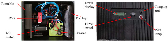
Figure 1.
The composition of the imaging device. The turntable drives the polarizer to rotate, causing a change in the brightness of the scene and triggering DVS imaging.
Based on polarized DVS imaging, Martin Nowak et al. proposed a high-precision neural network that classifies the motion speed and mode of targets using a limited number of events within a given time window. The results showed that the classification accuracy of motion speed and motion mode can reach 99% and 96%, respectively [21]. Michael Hawks et al. compared two methods to estimate the polarization state without recovering the irradiance image, and the preliminary experiments showed that there is some promise in applications for enhancing contrast or improving target detection, but it is not well suited for scenarios requiring precise polarization measurements, and data will need to be collected under more controlled and extensive conditions in the future to determine a repeatable and more robust method [22]. Changda Yan et al. utilized the principles of DVS to build an event-based imaging polarizer to obtain a stream of polarization events with high dynamic range and high temporal resolution, and proposed an event-based imaging polarimeter simulation method that can easily convert existing data into polarization event streams, enabling the creation of large datasets for deep learning models [23]. Germain Haessi et al. demonstrated this event-based polarization imager by placing polarizers directly in front of pixels, similar to RGB color imaging. The polarization state of each pixel was calculated by a deep neural network based on the surrounding pixels. They used a rotating polarizer to generate changing scenes. By varying the rotation speed of the target, the significant advantages of event-based sensors for fast-moving targets were demonstrated [24].
Polarized DVS imaging has broad application prospects in remote sensing as well as search and rescue [25,26,27]. However, remote sensing detection often requires a sufficiently large detection FOV and width to improve its detection efficiency [28,29]. However, according to our previous research [30], during large FOV polarization imaging, the polarization states at the edge and center of the detector’s FOV may become inconsistent, violating the paraxial approximation condition [31,32]. This inconsistency increases as the angle between the incident light and the optical axis increases, affecting the accuracy of target detection. To alleviate this issue, this paper proposes a DVS-based large FOV polarization imaging theory, in which the characteristics of polarization imaging, the rotation step size of the polarizer, the polarization state of the incident light, and the incident angle are jointly utilized. Furthermore, the influence of different incident conditions, i.e., linearly polarized light, natural light, and partially polarized light, on detection performance is analyzed.
2. DVS-Based Polarized Imaging Methods
A DVS was found to be sensitive to a moving target in a scene [33], and in the final analysis in another study, a DVS detected a change in the light and dark intensity of a target in its FOV [34]. For this reason, we thought of combining a DVS with polarization, adding a rotating polarizer in front of the DVS. This imaging method causes targets within the FOV with a high degree of polarization in their reflected light to produce brightness changes [35], which can then be detected by the DVS.
Assume that the contrast sensitivity of the DVS camera is C0, i.e., two adjacent events detected in the same position in the image with a contrast greater than C0 can be detected. Natural light reflected by the surface of an object will change into partially polarized light, and the proportion of these two parts can be described by the polarization degree of the partially polarized light, and the polarization degree Dop is defined as [36]
where IP represents the light intensity of the fully polarized light component, and IN represents the light intensity of the natural light component. For fully polarized light, Dop = 1; for natural light, Dop = 0; and for partially polarized light, 0 < Dop < 1.
Assuming that the angle between the direction of polarizer detection and the direction of the polarization of partially polarized light at the n-th detection by the DVS camera is ψ0, and the angle of polarizer rotation by the camera at the (n + 1)-st detection is STEP (i.e., the step of rotation), the intensities I1 and I2 obtained by the camera at the two exposures are assumed to be [37]
So, the contrast C is
According to the imaging mechanism of the DVS, the DVS can detect the event when C is larger than C0, which is related to the polarization degree, polarizer rotation speed, and initial phase (as shown in Equation (4)). However, the above equation is established on the premise that the polarized light satisfies the near-axis approximation condition. In other words, it follows Malus’s Law [38]. However, according to a previous study [28], when the FOV of a polarized imaging system is large, the incident polarized light from its edge FOV will no longer fully comply with Malus’s Law after the polarizer step.
3. Polarization Imaging Theory of Large FOV
Unlike paraxial beams, when oblique beams pass through a polarizer, the direction of the beams is no longer nearly perpendicular to the surface of the polarizer, causing the state of the oblique beams passing through the polarizer to deviate from that of the paraxial beams. Consequently, the intensity of the transmitted light no longer follows Malus’s law. In our previous work, we conducted in-depth research on the theory of polarization imaging with a large FOV. In order to make it easy for readers to understand, the research process and results are listed briefly here, and the details can be obtained from reference [28].
We introduce the concept of the transmission plane [39], the polarized light that can pass through the linear polarizer; its light vector must lie within the plane formed by the polarization direction of the polarizer and the normal of the polarizer, which is defined as the transmittance plane. Within the aperture through which light passes, only the component of the polarized light whose light vector lies within the transmission plane can pass through the polarizer.
On the basis of the transmittance plane, we establish the polarizer coordinate system oxyz and the light wave coordinate system oξηζ, as shown in Figure 2. Assuming that the polarizer is an ideal polarizer (the transmittance of natural light is 0.5, and the transmitted light is completely linearly polarized), and assuming that the incident light wave is linearly polarized light, and that the propagation direction is θ-angled with the direction of the polarizer’s optical axis; take the polarizer’s optical axis to be the z-axis, and the direction of the polarization of the polarizer to be the x-axis, and establish the polarizer coordinate system. It is obvious that the oxz-plane is the transmittance plane; take the direction of the incident light wave as the ζ-axis, and the direction of the light vector as the ξ-axis, which is perpendicular to the oζη-plane, and establish the right-handed helical coordinate system of the polarized light. oA is the intersection line between the oxy-plane and the oξη-plane, the angle with the ξ-axis is φ, the angle with the x-axis is ψ, and the intersection lines of the oξη-plane with the oxz-plane and the oyz-plane are oB and oC, respectively.
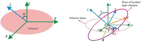
Figure 2.
Relationship between polarizer coordinate system and light wave coordinate system.
Let i, j, and k be the direction vectors of the x, y, and z axes, respectively. Accordingly, the unit vectors of the ζ-axis, the ξ-axis, and the η-axis can be expressed as
The direction vectors of the light-transparent axis oB and the light-impermeable axis oC are expressed as
where γx is the angle between the ζ-axis and the x-axis, and γy is the angle between the y-axis and the ζ-axis.
This yields the angle β between the light-transmitting axis oB and the light-impermeable axis oC as follows:
Figure 3 illustrates the relationship of the angle β between oB and oC, and Figure 4 shows the surface of the variation in β with θ and ψ. It can be seen that when light is obliquely incident θ ≠ 0, β ≥ π/2, i.e., the decomposition of the light vector is not an orthogonal decomposition.
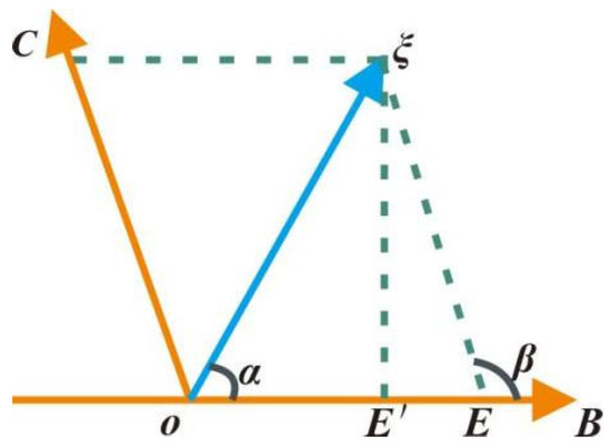
Figure 3.
Decomposition of the light wave vector in the oξη-plane.
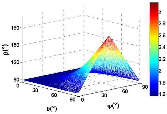
Figure 4.
The relationship between β, θ, and ψ.
Let the angle between the light vector ξ and the oB direction be α, and its component in the oB direction oE (i.e., the light vibration through the polarizer) be
Further let the angle of oB with the x-axis be δ; then,
The projection oF of oE on the x-axis, i.e., the transmitted light vibration obtained by the detector, is
The light source for space-based remote sensing detection is mainly sunlight, which can be considered natural light, but after reflection from an object, it generally changes to partially polarized light, and if the angle of incidence is the Brewster angle, the reflected light is fully polarized. From Equation (11), the light beams obliquely in the fringe FOV into the polarizer. The intensity of the transmitted light no longer follows Malus’s Law, but is related to the angle of incidence, the direction of vibration, and the direction of the polarizer, and, based on the polarization of the DVS imaging method, detects the change in the intensity of the light, and the change in the intensity of the transmitted light in the fringe FOV will have a direct effect on the detection capability.
4. DVS-Based Large FOV Polarization Imaging Theory
Large FOV polarization imaging in the detector edge FOV and the center FOV of the polarization state will be inconsistent, that is, it does not meet the near-axis approximation conditions, and with an increase in the angle between the incident light and the optical axis, the inconsistency increases, based on the dynamic vision sensor and based on the characteristics of the polarization imaging, taking into account factors such as the polarizer rotational step size, the polarization state of the incident light, and the angle of incidence, respectively, from the natural light, linearly polarized light, and partially polarized light; these are the three kinds of incident conditions used to study the theory of large FOV polarization imaging based on DVSs.
4.1. Incidence of Natural Light
Assume that a beam of natural light has intensity IN and the angle of the optical axis θ is incident to the polarized imaging system. By combining Equation (11) with the optical imaging theory [40], the light intensity received by the image plane is
where INα is the light intensity of any vibrational direction component of the incident natural light, i.e., IN = ∫INα dα, so that
Assuming that the polarizer is rotated by STEP degrees during the time interval of the DVS detection event, the light intensities received by the image plane before and after the rotation are IN1′ and IN2′, respectively.
Figure 5 (left) shows the relationship between εN and θ, ψ. Theoretically, if the outgoing light after a beam of natural light passes through the polarizer follows Malus’s Law, ε = 1. However, it can be seen from Figure 5 that as the angle of incidence θ and ψ vibrational direction increase, εN gradually decreases until it is 0, indicating that at this time, the outgoing light no longer follows Malus’s Law, and the polarization state of outgoing light at the edge of the FOV is changed, which has an impact on the imaging of the polarized DVS. The polarization state of the outgoing light in the fringe FOV changes, which affects the polarized DVS imaging. As shown in Figure 5 (right), there is no event triggered by the DVS when natural light is incident, but as θ and ψ increase in the fringe FOV, the event output is gradually generated, which is due to the change in the polarization state of the light in the fringe FOV, resulting in a “spurious” event. In this paper, we take the DAVIS346 camera produced by iniVation as an example; the time resolution of the event stream can reach the microsecond level, the circuit delay of the event camera is less than 1 ms, and the contrast sensitivity can reach as low as 14.3%. Therefore, the event output is generated when C is greater than 0.143, at which time a false event output is generated when θ is minimized to 84°. The event triggering for different STEP and θ values is shown in Table 1 and Figure 6.
Figure 5.
(Left): relationship between εN and θ, ψ, εN = IN1′/(2IN). (Right): step = 1°, relationship between C and θ, ψ.

Table 1.
Event triggering with different STEP and θ values for natural light incidence.
Figure 6.
Variation in event trigger proportions for different STEP and θ values with natural light incidence.
Originally, the paraxial incidence of natural light should not trigger the event, and the event trigger proportion should be 0%. However, due to the oblique incidence of the large FOV, the polarization state of the outgoing light changes, and the event is mistakenly triggered. As the step increases, the trigger proportion increases and the required angle of incidence θ becomes progressively smaller. At step = 10°, an event is triggered at θ = 50°; for the same step, the trigger proportion increases as θ increases. But when θ is small, none of the events will be triggered.
4.2. Linearly Polarized Light Incidence
Assuming that a beam of linearly polarized light of intensity IP with an optical axis angle of θ is incident to the polarization imaging system. According to Formula (11) and the optical imaging theory [23,30], the light intensity received by the image plane is
Assuming that the polarizer is rotated by STEP degrees during the time interval of the DVS detection event, the light intensities received by the image plane before and after the rotation are IP1′ and IP2′, respectively.
The relationship between εP and ψ, φ, is shown in Figure 7. When θ = 0°, εP follows Malus’s Law. When θ = 63°, i.e., oblique incidence, εP no longer follows Malus’s Law, but is related to the angle of incidence, the angle between the polarization direction and the detection direction, indicating that the polarization state of the outgoing light in the fringe FOV changes. As shown in Figure 8, the change in the polarization state of the incident light in the fringe FOV also affects the imaging of the polarization DVS, and when θ = 63°, with the increase in ψ, φ, the DVS will fail to detect the event, resulting in missed detection of the event. The event triggering For different STEP and θ values is shown in Table 2 and Figure 9.
Figure 7.
Relationship between εP and ψ, ϕ for θ = 0° (left) and θ = 63° (right), εP =IP1′/IP.
Figure 8.
θ = 63°, C versus ψ, φ. The right panel shows the image of the left panel as a function of C in the interval [0, 1].
Table 2.
Event triggering for different STEP and θ values at the incidence of linearly polarized light.
Figure 9.
Variation in event-triggered occupancy ratio for different STEP and θ values at the incidence of linearly polarized light.
Originally, the trigger proportion of linearly polarized light at paraxial incidence is consistent with that of θ = 0° in Table 2, but due to the oblique incidence of a large FOV, the polarization state of the outgoing light changes, and the trigger proportion of events decreases, resulting in a decline in detection accuracy. The event trigger proportion increases with increasing STEP, but the large fringe FOV leads to target leakage. The larger the incident angle θ is, the higher the leakage rate is for the same STEP. For the polarizer rotation speed, i.e., the rate of change in the polarizer angle, the event trigger proportion becomes larger and the leakage rate decreases with larger rotation speed (less than 90°).
4.3. Partially Polarized Light Incidence
Assuming a beam of partial polarization I = IP +IN, with polarization DOP = IP/I, incident at an angle of incidence θ into a polarized imaging system, from Equations (4), (14), (17) and (18), we can calculate the following:
Partially polarized light is a mixture of natural light and fully polarized light. Assuming that the fully polarized component of a beam of partially polarized light is line-polarized light and the polarization degree DOP = 0.9, the event triggering for different steps and θ values is shown in Table 3 and Figure 10. When the step is less than 3°, the event trigger proportion is basically less than 50%, and when the step is greater than 5°, the trigger proportion is generally higher than 50%, and it is higher than that of line-polarized light. The fact that it is higher than the case of linearly polarized light is due to the false alarm events generated by the natural light in the edge FOV, and the ratio will appear high and fluctuations low, because the linearly polarized light, in general, leads to an increase in θ followed by a decrease, and on the contrary, the natural light leads to an increase in θ followed by an increase, so it is the result of the mutual game of constraints.
Table 3.
Event triggering for different STEP and θ values at partial polarized light incidence.
Figure 10.
Variation in event-triggered occupancy ratio for different STEP and θ values for partially polarized light incidence.
In summary, for large FOV polarization imaging, the polarization state of incident light in the fringe FOV no longer follows Malus’s Law [41], resulting in a change in the polarization state. Thus, there is a misdetection of events in natural light incidence and a leakage of detection in linearly polarized light incidence. For partially polarized light incidence, it is an iterative situation of natural light and linearly polarized light. Overall, when the step is small, the property of natural light incidence is preferred, and when the step is large, the nature of linearly polarized light incidence is preferred.
5. Experiments
5.1. Linearly Polarized Light Incidence
The experimental device is shown in Figure 11. A GCL-050004 polarizer (the aperture was 45 mm, the thickness was 2 mm, the wavelength range was 400–700 nm, the FOV was ±45°, and the extinction ratio was 100:1) from Daheng Optics (Beijing China) was used. The rotating device was driven by a stepper motor, whose rotating speed could be adjusted. The maximum rotating speed was 48,000°/s. The model of DVS was a DAVIS 346 from Switzerland iniVation AG, and the minimum latency was 20 μs. The light source of the light box was a Standard Illuminant A [42]. After reflection by a glass plate with a refractive index of 1.5163 at an incident angle of 56.6° (Brewster angle) [43], the reflected light achieved a degree of polarization of 1.
Figure 11.
A schematic diagram of the linearly polarized light incidence experiment.
According to the experimental conditions, during 20 μs (the DVS minimum latency), the rotation step was 0.96°, approximately 1°. The glass plate was basically in the center of the FOV, and the incidence Angle θ was less than 10°. The experimental results are shown in Figure 12. The red box area is the glass plate; the area size is 15 × 14 pixels; the numbers of events output by the statistics are 47, 35, 119, and 53; and the trigger proportions are 0.24, 0.17, 0.57, and 0.25, with an average of 30.75%, and the error is 1.79% compared with the theoretical value of 28.96%, which is basically consistent.
Figure 12.
Four consecutive event images of the glass plate (The red box represents the glass plate area).
5.2. Incidence of Natural Light
The device shown in Figure 1 was used for street view imaging, and the relevant indicators were consistent with those in part 5.1. The experimental results are shown in Figure 13. We believed that the incident light in the sky is natural light, and the incident angle is also less than 10 degrees. The red box is the sky area. The trigger proportion of three consecutive event images is 0, which is consistent with the result in Section 4.1.
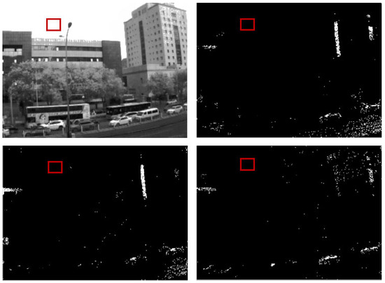
Figure 13.
Visible street view image (top left) and the remaining three consecutive event images (The red box represents the sky area).
Since there was no available source of adjustable polarized light in the laboratory, we only conducted natural light and linearly polarized light incident experiments, and the results showed that they were consistent with the theory. In the future, we will improve the experimental device, supplement and verify the theory, and improve the robustness of edge FOV detection so as to better support the improvement of numerical calculation accuracy such as automatic driving and three-dimensional surface reconstruction [44].
6. Conclusions
This paper introduces the DVS-based polarization imaging method and the large FOV polarization imaging theory. Furthermore, the DVS-based large FOV polarization imaging theory is investigated from the three kinds of incidence conditions, including natural light, linearly polarized light, and partially polarized light, in which several factors, i.e., the polarizer rotation step, the polarization state of the incident light, and the angle of incidence, are fully employed. The results show that the false detection of events and the missed detection of linearly polarized light incidence occur in the fringe FOV for large FOV polarization DVS imaging. Moreover, this situation is related to the angle of incidence, line polarization speed, and so on. Since the FOV of our DVS-based polarization imaging device is less than 10°, it is difficult to carry out better experimental tests. In the future, we will improve this device to increase the range of the FOV, and conduct more experiments to verify the imaging theory of this study.
Author Contributions
Conceptualization, X.L.; methodology, X.L. and L.X.; software, K.X.; validation, S.L.; analysis, X.L.; investigation, Z.G.; resources, L.X.; data curation, K.X.; writing—original draft preparation, X.L.; writing—review and editing, L.X.; visualization, S.L.; supervision, L.X.; project administration, L.X. All authors have read and agreed to the published version of the manuscript.
Funding
This study was funded by the National Natural Science Foundation of China (Grant No. 62205371).
Institutional Review Board Statement
Not applicable.
Informed Consent Statement
Not applicable.
Data Availability Statement
The data related to the paper are available from the corresponding authors upon reasonable request.
Conflicts of Interest
The authors declare no conflicts of interest.
References
- Chen, G.; Cao, H.; Conradt, J.; Tang, H.; Rohrbein, F.; Knoll, A. Event-based neuromorphic vision for autonomous driving: A paradigm shift for bio-inspired visual sensing and perception. IEEE Signal Process. Mag. 2020, 37, 34–49. [Google Scholar] [CrossRef]
- Yang, Y.; Pan, C.; Li, Y.; Yangdong, X.; Wang, P.; Li, Z.-A.; Wang, S.; Yu, W.; Liu, G.; Cheng, B.; et al. In-sensor dynamic computing for intelligent machine vision. Nat. Electron. 2024, 7, 225–233. [Google Scholar] [CrossRef]
- Gallego, G.; Delbrück, T.; Orchard, G.; Bartolozzi, C.; Taba, B.; Censi, A.; Leutenegger, S.; Davison, A.J.; Conradt, J.; Daniilidis, K.; et al. Event-based vision: A survey. IEEE Trans. Pattern Anal. Mach. Intell. 2020, 44, 154–180. [Google Scholar] [CrossRef] [PubMed]
- Linares-Barranco, A.; Perez-Pena, F.; Moeys, D.P.; Gomez-Rodriguez, F.; Jimenez-Moreno, G.; Liu, S.-C.; Delbruck, T. Low Latency Event-Based Filtering and Feature Extraction for Dynamic Vision Sensors in Real-Time FPGA Applications. IEEE Access 2019, 7, 134926–134942. [Google Scholar] [CrossRef]
- Drazen, D.; Lichtsteiner, P.; Häfliger, P.; Delbrück, T.; Jensen, A. Toward real-time particle tracking using an event-based dynamic vision sensor. Exp. Fluids 2011, 51, 1465–1469. [Google Scholar] [CrossRef]
- Cai, Z.; Tan, H.; Zhao, J.; Wang, Y. Target detection and obstacle avoidance for UAV based on dynamic vision sensor. J. Appl. Artif. Intell. 2024, 1, 192–214. [Google Scholar] [CrossRef]
- Wang, C.; Wang, X.; Fang, Y.; Yan, C.; Zhang, X.; Zuo, Y. Event-Enhanced Passive Non-Line-of-Sight Imaging for Moving Objects With Physical Embedding. IEEE Sens. J. 2024, 24, 37970–37985. [Google Scholar] [CrossRef]
- Fischer, T.; Milford, M.J. Event-Based Visual Place Recognition with Ensembles of Temporal Windows. IEEE Robot. Autom. Lett. 2020, 5, 6924–6931. [Google Scholar] [CrossRef]
- Wang, Y.; Zhou, Q.; Xiong, H.; Shen, Y.; Cheng, L. A Novel Dynamic Vision Sensor Image Rain Removal Method Based on Event Density Clustering. In Proceedings of the 2024 International Conference on Networking, Sensing and Control (ICNSC), Hangzhou, China, 18–20 October 2024; pp. 1–7. [Google Scholar]
- Lenz, G.; Ieng, S.-H.; Benosman, R. Event-Based Face Detection and Tracking Using the Dynamics of Eye Blinks. Front. Neurosci. 2020, 14, 587. [Google Scholar] [CrossRef]
- Zundel, A.; Demonceaux, C.; Hueber, N.; Spittler, D.; Strub, G.; Changey, S. Bimodal vision system combining standard camera and dynamic vision sensor for detecting and tracking fast UAVs. In Proceedings of the Emerging Imaging and Sensing Technologies for Security and Defence IX, SPIE, Edinburgh, UK, 17–18 September 2024; Volume 13204, p. 1320402. [Google Scholar]
- Yang, J.; Jin, W.Q.; Qiu, S.; Xue, F.D. Correction model for visible light polarization imaging considering non-ideality of polarizers. Opt. Precis. Eng. 2020, 28, 334–339. [Google Scholar]
- Wu, Y.Z.; Liu, X.; Yao, L. Polarization characteristics of the paint plate based on single reflection. In Proceedings of the AOPC 2017: Optical Sensing and Imaging Technology and Applications, Beijing, China, 4–6 June 2017; Volume 10462, pp. 487–494. [Google Scholar]
- Chen, H.S.; Rao, C.R.N. Polarization of light on reflection by some natural surfaces. J. Phys. D Appl. Phys. 1968, 1, 1191. [Google Scholar] [CrossRef]
- Wolff, L. Polarization-based material classification from specular reflection. IEEE Trans. Pattern Anal. Mach. Intell. 1990, 12, 1059–1071. [Google Scholar] [CrossRef]
- Kliger, D.S.; Lewis, J.W.; Randall, C.E. Polarized Light in Optics and Spectroscopy; Elsevier: Amsterdam, The Netherlands, 1990. [Google Scholar]
- Andreou, A.; Kalayjian, Z. Polarization imaging: Principles and integrated polarimeters. IEEE Sens. J. 2002, 2, 566–576. [Google Scholar] [CrossRef]
- Bueno, J.M.; Berrio, E.; Ozolinsh, M.; Artal, P. Degree of polarization as an objective method of estimating scattering. J. Opt. Soc. Am. A 2004, 21, 1316–1321. [Google Scholar] [CrossRef]
- Lu, X.; Li, F.; Xiao, B.; Yang, X.; Xin, L.; Liu, Z. Rotary polarization detection imaging system based on dynamic vision sensor. Opt. Precis. Eng. 2021, 29, 2754–2762. [Google Scholar] [CrossRef]
- Lu, X.; Li, F.; Xiao, B.; Yang, X.; Xin, L.; Liu, Z. Polarization imaging detection method based on dynamic vision sensor. In Proceedings of the Seventh Symposium on Novel Photoelectronic Detection Technology and Applications, SPIE, Kunming, China, 5–7 November 2020; Volume 11763, pp. 242–251. [Google Scholar]
- Nowak, M.; Beninati, A.; Douard, N.; Puran, A.; Barnes, C.; Kerwick, A.; Giakos, G.K. Polarimetric dynamic vision sensor p(DVS) neural network architecture for motion classification. Electron. Lett. 2021, 57, 624–626. [Google Scholar] [CrossRef]
- Hawks, M.; Dexter, M. Event-based imaging polarimeter. Opt. Eng. 2022, 61, 053101. [Google Scholar] [CrossRef]
- Haessig, G.; Joubert, D.; Haque, J.; Milde, M.B.; Delbruck, T.; Gruev, V. Pdavis: Bio-inspired polarization event camera. In Proceedings of the IEEE/CVF Conference on Computer Vision and Pattern Recognition, Vancouver, BC, Canada, 18–22 June 2023; pp. 3963–3972. [Google Scholar]
- Yan, C.; Wang, X.; Zhang, X.; Wang, C. Event-based imaging polarimeter simulation with a single DoFP image. Opt. Lett. 2023, 48, 739–742. [Google Scholar] [CrossRef] [PubMed]
- Nowak, M.; Beninati, A.; Douard, N.; Giakos, G.C. Polarimetric dynamic vision sensor p(DVS) principles. IEEE Instrum. Meas. Mag. 2020, 23, 18–23. [Google Scholar] [CrossRef]
- Douard, N.; Surovich, M.; Bauman, G.; Giakos, Z.; Giakos, G. A novel cognitive neuromorphic polarimetric dynamic vision system (pDVS) with enhanced discrimination and temporal contrast. In Proceedings of the 2018 Conference on Precision Electromagnetic Measurements (CPEM 2018), Paris, France, 8–13 July 2018; pp. 1–2. [Google Scholar]
- Morel, O.; Fofi, D. Visual behavior based bio-inspired polarization techniques in computer vision and robotics. In Developing and Applying Biologically-Inspired Vision Systems: Interdisciplinary Concepts; IGI Global: Hershey, PA, USA, 2013; pp. 243–272. [Google Scholar]
- Campbell, J.B.; Wynne, R.H. Introduction to Remote Sensing; Guilford Press: New York, NY, USA, 2011. [Google Scholar]
- Elachi, C.; Zimmerman, P.D. Introduction to the physics and techniques of remote sensing. Phys. Today 1988, 41, 126. [Google Scholar] [CrossRef]
- Lu, X.; Jin, W.; Li, L.; Wang, X.; Qiu, S.; Liu, J. Theory and analysis of a large field polarization imaging system with obliquely incident light. Opt. Express 2018, 26, 2495–2508. [Google Scholar] [CrossRef] [PubMed]
- Takenaka, T.; Yokota, M.; Fukumitsu, O. Propagation of light beams beyond the paraxial approximation. J. Opt. Soc. Am. A 1985, 2, 826–829. [Google Scholar] [CrossRef]
- Setälä, T.; Shevchenko, A.; Kaivola, M.; Friberg, A.T. Degree of polarization for optical near fields. Phys. Rev. E 2002, 66, 016615. [Google Scholar] [CrossRef] [PubMed]
- Weikersdorfer, D.; Adrian, D.B.; Cremers, D.; Conradt, J. Event-based 3D SLAM with a depth-augmented dynamic vision sensor. In Proceedings of the 2014 IEEE International Conference on Robotics and Automation (ICRA), IEEE, Hong Kong, China, 31 May–7 June 2014; pp. 359–364. [Google Scholar]
- Yang, M.; Liu, S.-C.; Delbruck, T. A dynamic vision sensor with 1% temporal contrast sensitivity and in-pixel asynchronous delta modulator for event encoding. IEEE J. Solid-State Circuits 2015, 50, 2149–2160. [Google Scholar] [CrossRef]
- DeBoo, B.; Sasian, J.; Chipman, R. Degree of polarization surfaces and maps for analysis of depolarization. Opt. Express 2004, 12, 4941–4958. [Google Scholar] [CrossRef]
- Schaefer, B.; Collett, E.; Smyth, R.; Barrett, D.; Fraher, B. Measuring the Stokes polarization parameters. Am. J. Phys. 2007, 75, 163–168. [Google Scholar] [CrossRef]
- Demos, S.G.; Alfano, R.R. Optical polarization imaging. Appl. Opt. 1997, 36, 150–155. [Google Scholar] [CrossRef]
- Brukner, C.; Zeilinger, A. Malus’ law and quantum information. Acta Phys. Slovaca 1999, 49, 647–652. [Google Scholar]
- Chen, X.Y.; San, M. Description of effect of polarimeter with slanting ray. Opt. Technol. 2006, 32, 425–427. [Google Scholar]
- Sharma, K.K. Optics: Principles and Applications; Elsevier: Amsterdam, The Netherlands, 2006. [Google Scholar]
- Ivchenko, V. Malus’ law revisited. Rev. Cuba. Física 2023, 40, 75–77. [Google Scholar]
- Godo, K.; Kinoshita, K.; Nakazawa, Y.; Ishida, K.; Fujiki, A.; Nikai, M.; Niimi, Y.; Teranishi, H.; Nishioka, T. LED-based standard source providing CIE standard illuminant A for replacing incandescent standard lamps. Measurement 2024, 239, 115479. [Google Scholar] [CrossRef]
- Fu, Q.; Liu, X.; Wang, L.; Zhan, J.; Zhang, S.; Zhang, T.; Li, Z.; Duan, J.; Li, Y.; Jiang, H. Analysis of target surface polarization characteristics and inversion of complex refractive index based on three-component model optimization. Opt. Laser Technol. 2023, 162, 109225. [Google Scholar] [CrossRef]
- Muglikar, M.; Bauersfeld, L.; Moeys, D.P.; Scaramuzza, D. Event-based shape from polarization. In Proceedings of the IEEE/CVF Conference on Computer Vision and Pattern Recognition, Vancouver, BC, Canada, 18–22 June 2023; pp. 1547–1556. [Google Scholar]
Disclaimer/Publisher’s Note: The statements, opinions and data contained in all publications are solely those of the individual author(s) and contributor(s) and not of MDPI and/or the editor(s). MDPI and/or the editor(s) disclaim responsibility for any injury to people or property resulting from any ideas, methods, instructions or products referred to in the content. |
© 2025 by the authors. Licensee MDPI, Basel, Switzerland. This article is an open access article distributed under the terms and conditions of the Creative Commons Attribution (CC BY) license (https://creativecommons.org/licenses/by/4.0/).