Article

Mid-Infrared Ultraflat Broadband Supercontinuum Generation with 10 dB Bandwidth of 2340 nm in a Tapered Fluorotellurite Fiber

1
State Key Laboratory of Materials Low-Carbon Recycling, Beijing University of Technology, Beijing 100124, China
2
Key Lab of Semiconductor Materials Science, Institute of Semiconductors, Chinese Academy of Sciences, Beijing 100083, China
*
Authors to whom correspondence should be addressed.
Photonics 2025, 12(4), 297; https://doi.org/10.3390/photonics12040297
Submission received: 16 February 2025 / Revised: 12 March 2025 / Accepted: 13 March 2025 / Published: 24 March 2025
(This article belongs to the Special Issue Advanced Lasers and Their Applications, 2nd Edition )

Abstract

:
We demonstrate mid-infrared ultraflat broadband supercontinuum (SC) generation in a 40 cm long tapered fluorotellurite fiber pumped by a Raman soliton source. By tapering the end of the large-core-diameter fluorotellurite fiber, the dispersion is regulated and the nonlinear effect is enhanced, which effectively extends the mid-infrared SC spectral range and increases the spectral flatness. Finally, we obtained an SC light source with a spectral range from 1.8 to 4.7 μm; the 10 dB bandwidth of the source completely covers 1.88–4.22 μm, which has the farthest flat spectral edge in fluorotellurite fibers. The output power of the SC laser is about 1.04 W, and the power ratio of those above 3 μm in the spectrum to the total SC is ~24%. The optical-to-optical conversion efficiency is about 75%. Our results show that tapering of fluorotellurite fiber is an effective method to further extend and flatten the mid-infrared SC.

1. Introduction

Recently, 2–5 μm mid-infrared (MIR) supercontinuum (SC) laser sources have attracted much attention and found significant application in frequency metrology, long-distance remote sensing, defense, and security [1,2,3,4,5]. Recently, many efforts have been made to improve the output power [6,7,8,9], extend the spectral range [10,11,12], and enhance the spectral flatness of MIR SC laser sources [13,14]. In particular, some fields such as medical diagnostics [15] and hyperspectral imaging [16] benefit from a broader and flatter bandwidth, which extends the spectrum in the MIR range, enhancing both detection resolution and sensitivity. In previous studies, fluoride fibers were often used to generate flat SC with 10 dB bandwidths covering 2–4 μm. Wu et al. reported an 11.3 W all-fiber mid-infrared SC laser source with a 10 dB bandwidth spectral range of 1.9–4.3 µm using fluoroindate fibers as the nonlinear media [17]. Yin et al. utilized fluoride fiber as nonlinear medium to generate an SC source with an output power of 15.2 W and a 10 dB bandwidth of 2090 nm (1960~4050 nm) [18]. Yang et al. used a 1.9–2.6 µm SC laser to pump a fluoride fiber, obtaining a MIR SC source with an output power of 20.6 W and a 10 dB bandwidth spectral range of 1.92–4.08 µm [19]. Although the high-power broadband SC is widely realized, fluoride fibers have poor chemical and thermal stability, and it is difficult to achieve long-term stable work in real applications [20].
In recent years, fluorotellurite fibers (TBY) with a broadband transmission window of 0.4–6 µm and excellent chemical and thermal stability have been researched extensively in MIR SC generation [21]. The fluorotellurite fiber has large nonlinear refraction, allowing the use of fibers as short as tens of centimeters in length, which is beneficial for thermal management. Yao et al. reported on an SC light source using a 6.8 μm core diameter fluorotellurite fiber as a nonlinear medium; the spectral range covers 0.95–3.93 μm with 10.4 W output power. The superior long-term stability of fluorotellurite fibers was verified [22]. Li et al. obtained a 22.7 W MIR SC source with a 10 dB spectral bandwidth ranging from 1890 to 3523 nm in 11 μm core diameter fluorotellurite fiber [13]. Guo et al. reported a 25.8 W SC light source with a 10 dB spectral bandwidth ranging from 2000 to 3500 nm in a fluorotellurite fiber [14]. To significantly increase the output power of the SC laser source, Jiao et al. use a large-core-diameter fluorotellurite fiber of 30 μm to generate a high-power SC. A 50 W all-fiber MIR SC light source with a 10 dB spectral range of 1400~3250 nm was obtained [23]. Although large-core-diameter fibers effectively increase SC power, the reduction in nonlinear coefficients results in the limitation of spectral broadening. As with the 2 μm light source or broad-spectrum light source used by the above researchers to pump the fluorotellurite fiber, the energy of the pump pulse is mainly concentrated at ~2 μm, resulting in low energy proportions at the long wavelength of the SC spectrum. Recently, Yang et al. demonstrated a 10.4 W flat SC light source with a 10 dB spectral range of 1.9–4.1 μm in a 34 μm core diameter fluorotellurite fiber [24]. The broadband and flat SC are caused by the excitation of 2180 nm as well as 2350 nm dual Raman soliton lasers. Although the SC spectrum has been effectively extended by improving the light source, due to the long-wavelength absorption loss of the fluorotellurite fiber, the spectrum is limited to within ~4 μm. Thus, it is still necessary to explore other ways to extend the spectral range and enhance the spectral flatness of MIR SC light sources.
In this paper, we experimentally demonstrate an MIR ultraflat broadband SC with a long-wavelength edge beyond 4700 nm, with a 10 dB bandwidth of about 2340 nm, generated in tapered fluorotellurite fibers pumped by a Raman soliton source. By introducing a tapered fiber part at the end of the LMA fluorotellurite fiber, the dispersion is regulated and the nonlinear effect is enhanced. In comparison with previous works on fluorotellurite fiber-based SC laser sources, the 10 dB bandwidth of the generated SC light in the tapered fiber is improved very much.

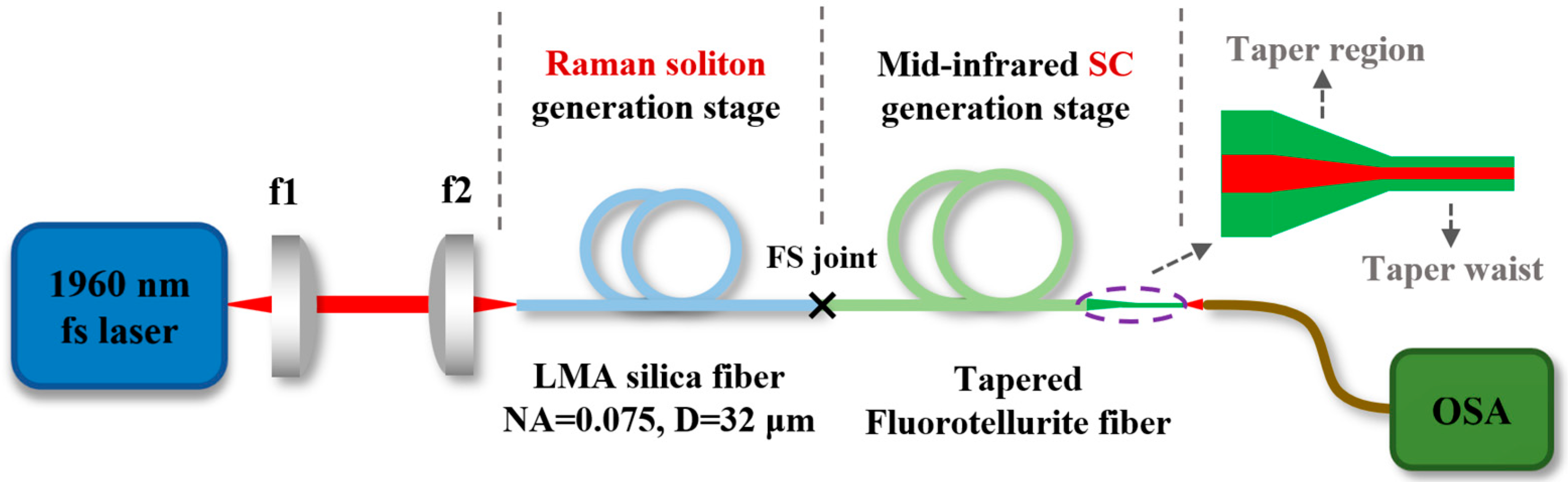
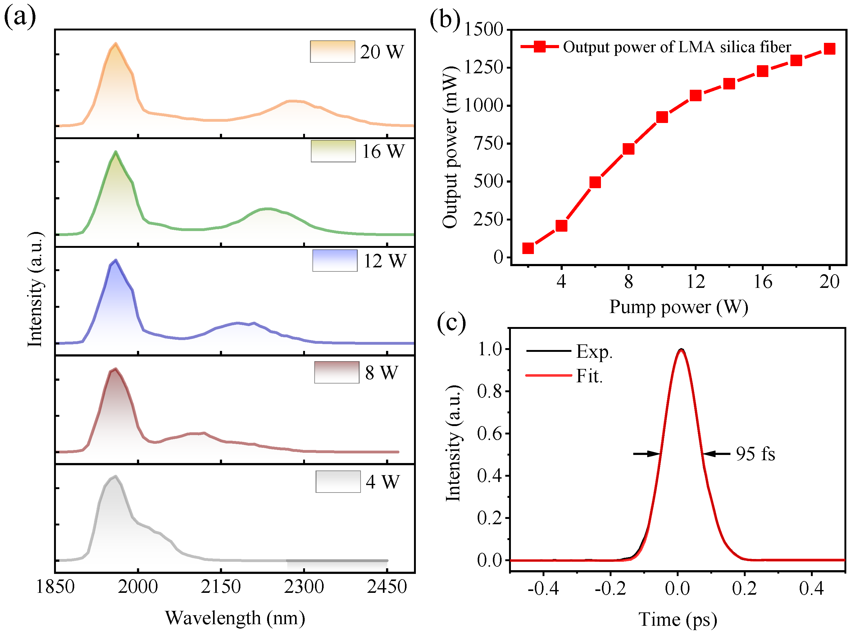
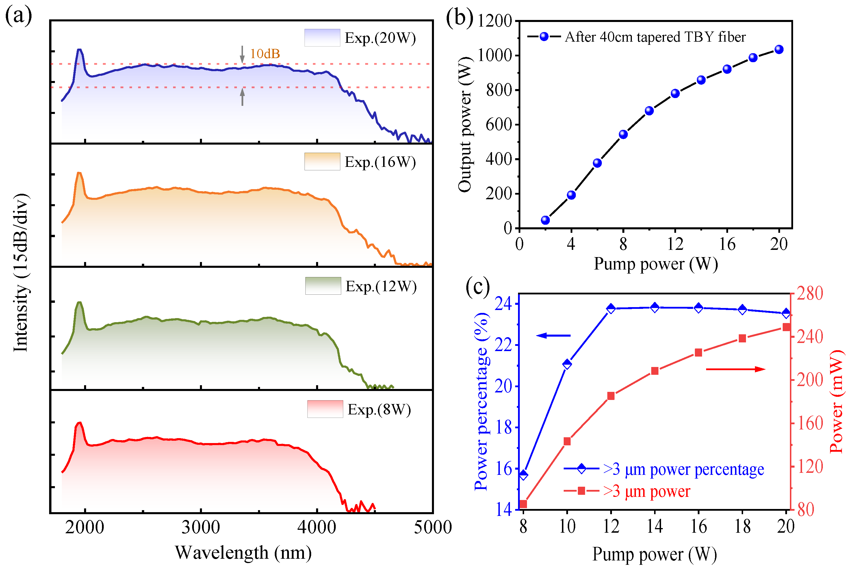
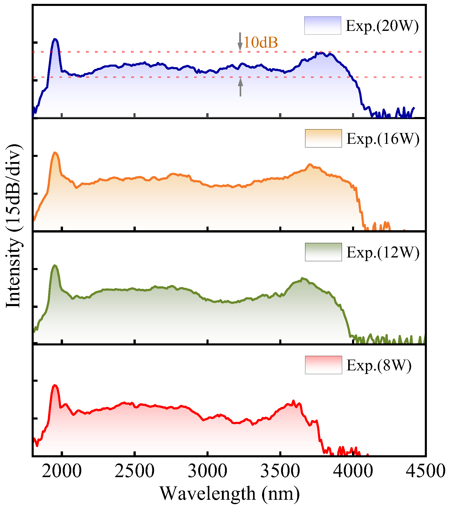
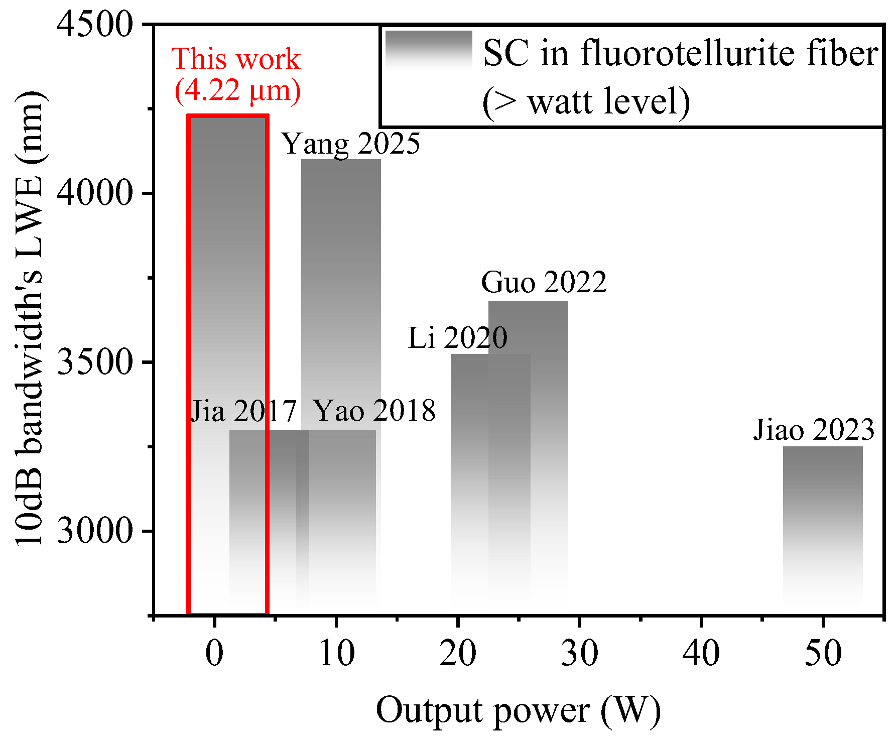
2. Experiments and Results

In our experiments, the core, the inner cladding, and the outer cladding materials for fluorotellurite fibers we selected were 70TeO2–20BaF2–10Y2O3 (70TBY), and 65TeO2-25BaF2-10Y2O3 (65TBY) and 60TeO2-30BaF2-10Y2O3 (60TBY), respectively; the refractive indexes are shown in Figure 1a. The three fluorotellurite glasses have similar glass transition temperatures (Tg) (~424 °C for 70TBY, ~422 °C for 65TBY, ~421 °C for 60TBY) and have high stability. Thus, the materials are suitable for fiber drawing and further heated tapering. All-solid double-clad fluorotellurite fibers (38/76/250 μm) were prepared using the secondary suction method [25], and the numerical apertures (NAs) of the fiber’s core and inner cladding at 2 µm are all about 0.3. The background loss value of the fiber at 1.5 μm was about 0.2 dB/m by using a cut-back method. Subsequently, a tapered fiber was fabricated by using a melt-drawn fiber taper system. The homemade fluorotellurite fiber has a 34 cm long untapered region with a 38 μm core diameter, a 2 cm long tapered transition region, and a 4 cm long taper waist with a 14 μm core diameter, as shown in Figure 1b. The dispersion curves of this fiber with different core diameters were calculated using the commercial software MODE solutions 7.11.1584 for x64 (Lumerical Solutions, Inc., Vancouver, BC, Canada) with the full vectorial finite difference method; the results are shown in Figure 1c. The first zero-dispersion wavelengths (ZDWs) of the fiber are all located at ~2.1 μm, and with the fiber core diameter reduced, the second ZDWs are generated and move to the shorter wavelength. The nonlinear coefficient (γ) curves of fibers with different core diameters were calculated by using a nonlinear refractive index of 3.5 × 10⁻¹⁹ m2W−1 for fluorotellurite glasses [13], as shown in Figure 1d.
Figure 2 shows the experimental setup for MIR SC generation in TBY fiber, including a 1960 nm femtosecond laser source, a lens-coupling system, a high-peak power Raman soliton generation stage, and an MIR SC generation stage, utilizing the tapered fluorotellurite fiber. Similarly to our previous work, the seed source of the 1960 nm femtosecond laser is a 1.95 μm Raman soliton obtained by a 1.5 μm femtosecond laser pumping a 1.6 m highly nonlinear germanate fiber (germanium concentration 98 mol.%) [24]. A commercially available chirped fiber Bragg grating (CFBG, TERAXION) and a pair of transmission gratings are used as the broadener and compressor, respectively. The compressed pulse laser is coupled into a large-mode-area (LMA) silica fiber through an aspherical mirror-coupling system for self-compression and Raman soliton self-frequency shift (SSFS). To avoid a large loss of Raman solitons moving to the long-wavelength region in the silica fiber, we chose a 23 cm long 32/250 LMA silica fiber, whose smaller NA (0.075) ensures high beam quality (M2 = 1.32) of output laser. At the MIR SC generation stage, a tapered 40 cm long TBY double-clad fiber, mentioned earlier, was fusion-spliced to the silica fiber to broaden the spectrum. The output signals of the MIR-SC light source were monitored using an optical spectrum analyzer and a power meter.
In the experiment, by using an acousto-optic modulator (AOM), the repetition frequency of the 1960 nm femtosecond pump source is reduced to 980 kHz to increase the peak power of the pulse. The center wavelength of the source is located at about 1960 nm, and the corresponding pulse width is about 500 fs. Initially, we couple 1960 nm ultrashort pulses into a 32/250 fiber with a coupling efficiency of ~73% using a precise fundamental-mode-matching technique. As shown in Figure 3a, with the increase in pump power, the split Raman soliton in the LMA silica fiber gradually shifts to the long-wavelength region. Since the ZDW of the LMA silica fiber is located at ~1.3 µm, the pump pulse operates in the anomalous dispersion regime, and soliton-related dynamics cause spectral broadening [26]. Continuing to increase the pump power to 20 W, the Raman soliton is frequency-shifted to ~2.3 µm, and then stops shifting, constrained by high losses of the silica fiber at longer wavelengths. As shown in Figure 3b, the output power of the LMA silica fiber increases to 1.38 W as the pump power rises from 2 W to 20 W. We calculated the power of the split Raman soliton by integrating the spectral area, finding that it constitutes approximately 29% of the total power, with a pulse energy of about 405 nJ. Figure 3c gives the corresponding pulse width of about 95 fs at 20 W pump power, and the peak power of the Raman soliton is calculated to be about 4.2 MW.
Figure 4a shows the spectrum evolution of the generated SC laser under different output powers from the above tapered fluorotellurite fiber. When the pump power is ≥8 W (the corresponding average output power is ≥540 mW), the Raman soliton generated in LMA silica fiber is located in the anomalous dispersion region of the above fluorotellurite fiber; large spectral broadening was caused by self-phase modulation, higher-order soliton compression, soliton fission, and the Raman soliton self-frequency shift. As the launched average pump power was increased to 20 W, the long-wavelength edge was extended to 4.7 µm. The 10 dB bandwidth of the generated SC light was about 2340 nm, excluding the pump light, and the corresponding spectral range was from 1880 to 4220 nm with excellent flatness. Figure 4b shows the dependence of the output power of the generated SC light in the above tapered fluorotellurite fiber on the power of the pump laser. The measured average output power of the generated SC laser was gradually increased to 1.04 W with the pump power being increased to 20 W, and the corresponding optical-to-optical conversion efficiency is about 75% (1.38 W to 1.04 W) in the fluorotellurite fiber.
By integrating the spectral area, we calculated the ratios of the power above 3 μm in the spectrum to the total spectral power. Figure 4c shows the power of above 3 μm in the spectrum and its percentage relative to different pump powers. The power ratio above 3 μm first increases with the increase in pump power, and then when the pump power exceeds 12 W, it almost holds at ~24%, before slightly decreasing. The low power percentage of above 3 μm in the spectrum at <12 W pump power is mainly because the Raman soliton has not yet fully shifted into the abnormal dispersion region of the TBY fiber to form a large spectral broadening. When the pump power exceeds 12 W, the decrease in the >3 μm power percentage in the SC spectrum is due to increased fiber loss as the spectrum extends towards longer wavelengths, resulting in energy loss in the long-wavelength portion. Corresponding to this process is a slower increase for >3 μm of power in the SC spectrum.
To verify the effect of fiber tapering on spectral broadening, we conducted experiments using a 38 μm core diameter untapered TBY fiber with the same length of 40 cm. Similarly to the above experimental process, we tested the output spectrum of the untapered TBY fiber at different pump powers, and the results are shown in Figure 5. As the pump power increases, the spectral long-wavelength edge slowly extends to about 4 μm and then the spectrum almost stops broadening. At a maximum pump power of 20 W, the long-wavelength edge was extended to about 4.1 µm. The 10 dB bandwidth of the generated SC light source was about 2080 nm, excluding the pump light, and the corresponding spectral range was from 1900 to 3980 nm. The output power of the generated SC light in the untapered fluorotellurite fiber is almost the same as in Figure 4b. Compared to the spectrum obtained in the above tapered TBY fiber, the SC spectrum obtained in the untapered fiber is slightly narrower, and, more notably, the spectral flatness is poor. In addition, due to the significant loss of the TBY fiber at long wavelengths, the intensity of the SC spectrum sharply decreases in wavelengths above 4 μm. This can be explained by combining the dispersion curve in Figure 1c and the nonlinear coefficient in Figure 1d. The tapered part at the end of the TBY fiber enhances nonlinear effects and adjusts dispersion, achieving further spectral broadening in long-wavelength regions and flattening the SC spectrum. The experimental results demonstrate that fluorotellurite fiber tapering is an effective method for overcoming fiber loss limitation and achieving further spectral broadening.
Figure 6 presents a comparison of TBY-fiber-based SC laser sources. In addition, we have summarized various parameters of TBY-fiber-based SC laser sources in Table 1. In our study, the long-wavelength edge (LWE) of the SC spectrum extends 550 nm compared to previous results in a TBY fiber. Note that although the power of the whole SC only reaches the watt level, the power ratio of the long-wavelength spectrum is greatly increased compared to previous reports. To the best of our knowledge, our result has the farthest flat spectral edge in fluorotellurite fibers.

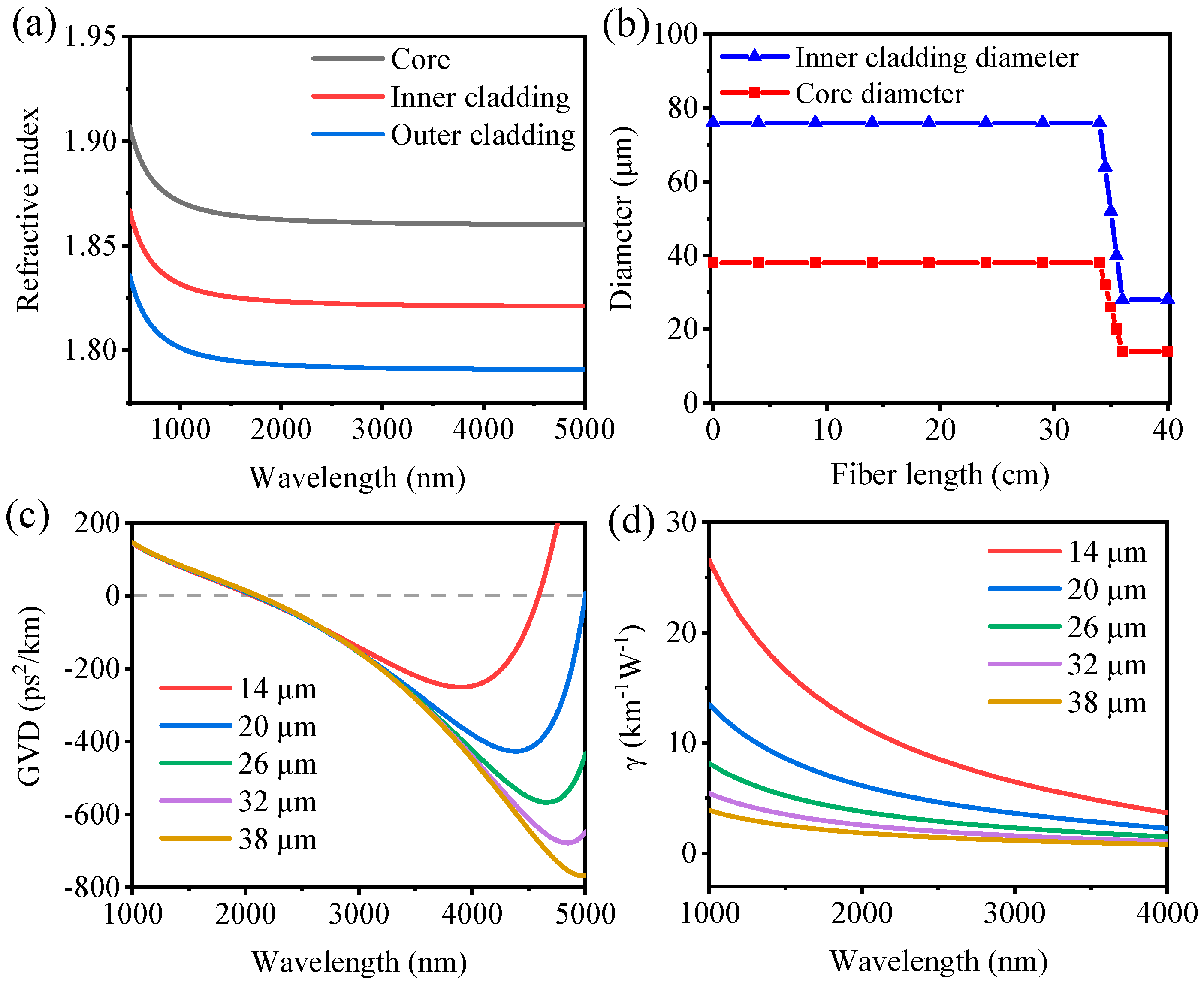
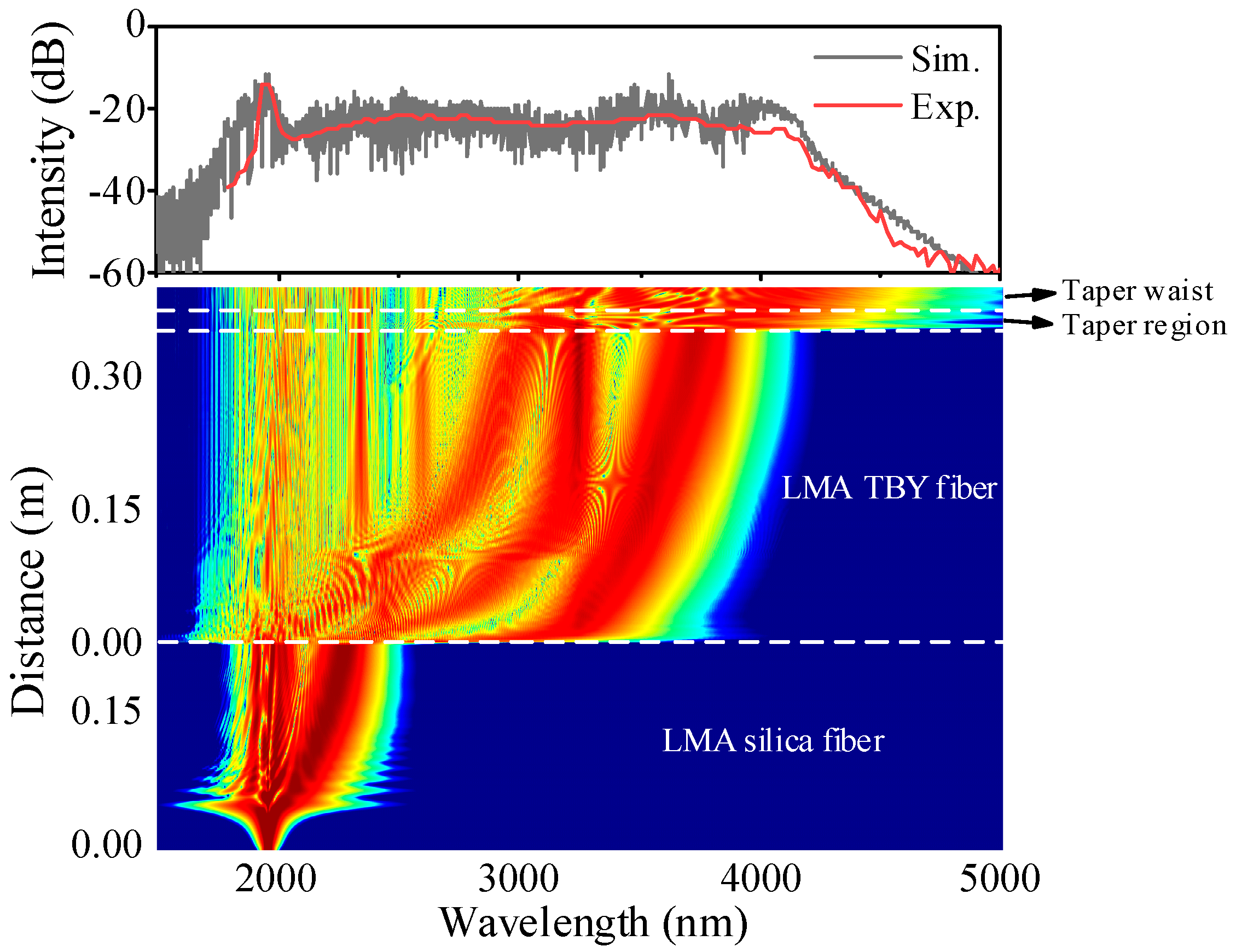
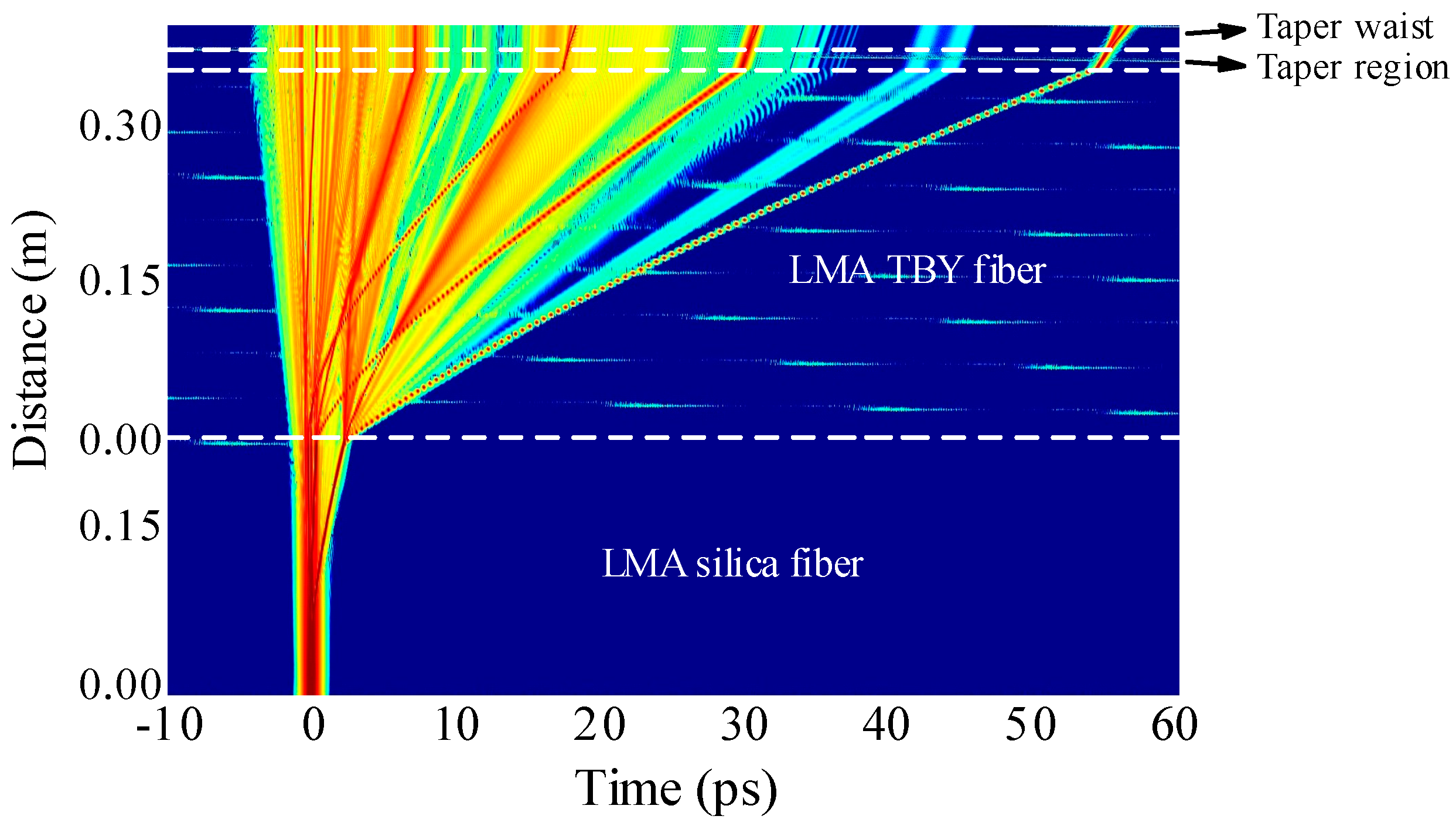
3. Simulation and Discussions

To verify the spectral broadening mechanism of SC lasers in the tapered TBY fiber (pump power 20 W), we have simulated the SC spectral domain evolution processes in the LMA silica fiber and the LMA TBY fiber pumped by femtosecond Raman soliton by solving the generalized nonlinear Schrodinger equation (GNLSE) [27,28]:
A z , t Z = α 2 A z , t + n = 1 i n + 1 β n n ! n A z , t T n + i γ 1 + i ω 0 t ( A ( z , t ) + R ( t ) | A ( z , t t ) | 2 d t )
where A(z,t) is the complex temporal profile, α is the fiber loss, βn is the dispersion coefficient associated with the Taylor expansion of the propagation constant at the reference frequency, γ is the nonlinear coefficient, and τshock is the additional shock time. R(t) is the Raman response function that includes both instantaneous electronic and delayed Raman contributions.
The initial pump pulses possessed a hyperbolic secant field profile:
A 0 , T = P 0 s e c h ( T / T 0 )
where P0 and T0 are the peak power and input pulse width, respectively. The Raman soliton order of the pump pulse was calculated as:
N 2 = L D L N L = γ P 0 T 0 2 | β 2 |
The split-step Fourier method was used to solve the GNLSE, and 217 time and frequency discretization points and a longitudinal step size <5 µm were used to ensure the accuracy of the numerical simulations.
In our numerical simulation, the pulse propagation is divided into four stages: a 23 cm long LMA silica fiber, a 0.34 m long LMA TBY fiber, a 2 cm long taper region of the TBY fiber, and a 4 cm long small-core-diameter TBY fiber, which corresponds to the fibers used in the experiment. The initial pulse parameters include the operating wavelength (1.95 μm), pulse width (500 fs), input power (1.38 W), and repetition frequency (980 kHz). In addition, the nonlinear coefficients, group velocity dispersion curves, and loss curves of the TBY fibers are also imported into the MATLAB simulation program. The Raman response function of the silica fiber is described in paper [29] and the Raman response function of the TBY fiber is derived from the Raman gain spectrum of fluorotellurite glass [22].
The simulated spectral and temporal evolution process of the pulse in the LMA silica fiber as well as in the LMA TBY fiber are shown in Figure 7 and Figure 8, respectively. For the pump pulse propagation inside the silica fiber segment from 0 to 0.05 m, the spectral broadening was caused by self-phase modulation (SPM). The femtosecond pulse is compressed to its narrowest point at 0.05 m, and then the first Raman soliton is split out. Next, the split Raman soliton in the LMA silica fiber is gradually shifted to the long-wavelength region (~2.4 μm) and enters the TBY fiber. The large spectral broadening inside the fluorotellurite fiber was mainly caused by self-phase modulation, soliton fission, and the Raman soliton self-frequency shift. Noting that the SC spectrum was further extended to 4.7 μm and flattened at the long-wavelength region due to the enhancement of the nonlinear effect caused by the tapered fiber part. According to Figure 1c, as the fiber core diameter decreases to 14 μm, the wavelength above 4.5 μm is located in the anomalous dispersion region of the fiber. However, in the simulations and experiments, we did not observe the formation of dispersion waves at about 5 μm. This can be explained by the higher transmission loss of TBY fiber at longer wavelengths. Figure 7 shows the results of the experimental spectrum and the simulated spectrum at the 20 W pump power, which confirms the above interpretation. Engineering of the nonlinearity and dispersion of a nonlinear fiber could be a more promising way to further improve the performance of the SC spectrum.

4. Conclusions

In conclusion, we obtained an ultraflat SC spectrum with a 10 dB bandwidth of 2340 nm in a home-made tapered TBY fiber. A high-peak-power Raman soliton femtosecond laser was used as the pump source, which was obtained by SSFS technique in a 0.23 m-long LMA silica fiber. A tapered TBY fiber is efficiently fused to the LMA silica fiber to enhance the stability of the system. The tapered part at the end of the fiber increases the nonlinear coefficient and regulates the dispersion, and then the SC spectrum was further broadened and flattened at the long-wavelength region. Our results show that tapering of a fluorotellurite fiber is an effective method to obtain an MIR ultraflat broadband supercontinuum.

Author Contributions

Conceptualization, G.R. and C.Y.; Data curation, G.R. and K.L.; Funding acquisition, C.Y.; Investigation, G.R. and L.P.; Methodology, L.Y.; Project administration, X.W.; Software, X.W. and L.Z.; Supervision, L.Z. and P.L.; Writing—original draft, G.R.; Writing—review and editing, L.Y. and C.Y. All authors have read and agreed to the published version of the manuscript.

Funding

This research was funded by “the National Natural Science Foundation of China” (grant number 62005004, 61675009) and “the Natural Science Foundation of Beijing Municipality” (grant number 4204091, KZ201910005006).

Institutional Review Board Statement

Not applicable.

Informed Consent Statement

Not applicable.

Data Availability Statement

The data underlying the results presented in this paper are not publicly available at this time but may be obtained from the authors upon reasonable request.

Conflicts of Interest

The authors declare no conflicts of interest.

References

  1. Gasser, C.; Kilgus, J.; Harasek, M.; Lendl, B.; Brandstetter, M. Enhanced mid-infrared multi-bounce ATR spectroscopy for online detection of hydrogen peroxide using a supercontinuum laser. Opt. Express 2018, 26, 12169–12179. [Google Scholar] [CrossRef] [PubMed]
  2. Ycas, G.; Giorgetta, F.R.; Baumann, E.; Coddington, I.; Herman, D.; Diddams, S.A.; Newbury, N.R. High-coherence mid-infrared dual-comb spectroscopy spanning 2.6 to 5.2 µm. Nat. Photonics 2018, 12, 202–208. [Google Scholar] [CrossRef]
  3. Timmers, H.; Kowligy, A.; Lind, A.; Cruz, F.C.; Nader, N.; Silfies, M.; Ycas, G.; Allison, T.K.; Schunemann, P.G.; Papp, S.B.; et al. Molecular fingerprinting with bright, broadband infrared frequency combs. Optica 2018, 5, 727–732. [Google Scholar] [CrossRef]
  4. Borondics, F.; Jossent, M.; Sandt, C.; Lavoute, L.; Gaponov, D.; Hideur, A.; Dumas, P.; Février, S. Supercontinuumbased Fourier transform infrared spectromicroscopy. Optica 2018, 5, 378–381. [Google Scholar] [CrossRef]
  5. Nallala, J.; Lloyd, G.R.; Kendall, C.; Shepherd, N.A.; Barr, H.; Stone, N. Identification of GI cancers utilizing rapid mid-infrared spectral imaging. Proc. SPIE 2016, 9703, 970303. [Google Scholar]
  6. Yang, W.; Zhang, B.; Xue, G.; Yin, K.; Hou, J. Thirteen watt all-fiber midinfrared supercontinuum generation in a single mode ZBLAN fiber pumped by a 2 µm MOPA system. Opt. Lett. 2014, 39, 1849–1852. [Google Scholar] [CrossRef]
  7. Yang, L.; Li, Y.; Zhang, B.; Wu, T.; Zhao, Y.; Hou, J. 30-W supercontinuum generation based on ZBLAN fiber in an all-fiber configuration. Photonics Res. 2019, 7, 1061–1065. [Google Scholar] [CrossRef]
  8. Zheng, Z.J.; Ouyang, D.Q.; Zhao, J.Q.; Liu, M.Q.; Ruan, S.C.; Yan, P.G.; Wang, J.Z. Scaling all-fiber mid-infrared supercontinuum up to 10 W-level based on thermal-spliced silica fiber and ZBLAN fiber. Photonics Res. 2016, 4, 135–139. [Google Scholar] [CrossRef]
  9. Shi, H.; Feng, X.; Tan, F.; Wang, P.; Wang, P. Multi-watt mid-infrared supercontinuum generated from a dehydrated large-core tellurite glass fiber. Opt. Mater. Express 2016, 6, 3967–3976. [Google Scholar] [CrossRef]
  10. Xia, C.; Xu, Z.; Islam, M.N.; Terry, F.L.; Freeman, M.J.; Zakel, A.; Mauricio, J. 10.5 W time-averaged power mid-IR supercontinuum generation extending beyond 4 µm with direct pulse pattern modulation. IEEE J. Sel. Top. Quantum Electron. 2009, 15, 422–434. [Google Scholar] [CrossRef]
  11. Kedenburg, S.; Strutynski, C.; Kibler, B.; Froidevaux, P.; Désévédavy, F.; Gadret, G.; Jules, J.; Steinle, T.; Mörz, F.; Steimnann, A.; et al. High repetition rate mid-infrared supercontinuum generation from 1.3 to 5.3 µm in robust step-index tellurite fibers. J. Opt. Soc. Am. B 2017, 34, 601–607. [Google Scholar] [CrossRef]
  12. Thapa, R.; Rhonehouse, D.; Nguyen, D.; Wiersma, K.; Smith, C.; Zong, J.; Chavez-Pirson, A. Mid-IR supercontinuum generation in ultra-low loss, dispersion-zero shifted tellurite glass fiber with extended coverage beyond 4.5 µm. Proc. SPIE 2013, 8898, 889808. [Google Scholar]
  13. Li, Z.R.; Jia, Z.X.; Yao, C.F.; Zhao, Z.P.; Li, N.; Hu, M.L.; Ohishi, Y.; Qin, W.P.; Qin, G.S. 22.7  W mid-infrared supercontinuum generation in fluorotellurite fibers. Opt. Lett. 2020, 45, 1882–1885. [Google Scholar] [CrossRef] [PubMed]
  14. Guo, X.H.; Jia, Z.X.; Jiao, Y.D.; Li, Z.R.; Yao, C.F.; Hu, M.L.; Ohishi, Y.; Qin, W.P.; Qin, G.S. 25.8 W all-fiber mid-infrared supercontinuum light sources based on fluorotellurite fibers. IEEE Photonics Technol. Lett. 2022, 34, 367–370. [Google Scholar] [CrossRef]
  15. Labruyère, A.; Tonello, A.; Couderc, V.; Huss, G.; Leproux, P. Compact supercontinuum sources and their biomedical applications. Opt. Fiber Technol. 2012, 18, 375–378. [Google Scholar] [CrossRef]
  16. Islam, M.N.; Freeman, M.J.; Peterson, L.M.; Ke, K.; Ifarraguerri, A.; Bailey, C.; Baxley, F.; Wager, M.; Absi, A.; Leonard, J.; et al. Field tests for round-trip imaging at a 1.4 km distance with change detection and ranging using a short-wave infrared supercontinuum laser. Appl. Opt. 2016, 55, 1584–1602. [Google Scholar] [CrossRef]
  17. Wu, T.; Yang, L.; Dou, Z.; Yin, K.; He, X.; Zhang, B.; Hou, J. Ultra-efficient, 10-watt-level mid-infrared supercontinuum generation in fluoroindate fiber. Opt. Lett. 2019, 44, 2378–2381. [Google Scholar] [CrossRef]
  18. Yin, K.; Zhang, B.; Yang, L.; Hou, J. 15.2 W spectrally flat all-fiber supercontinuum laser source with >1 W power beyond 3.8 μm. Opt. Lett. 2017, 42, 2334–2337. [Google Scholar] [CrossRef]
  19. Yang, L.; Zhang, B.; He, X.; Deng, K.; Liu, S.; Hou, J. 20.6 W mid-infrared supercontinuum generation in ZBLAN fiber with spectrum of 1.9–4.3 µm. J. Light. Technol. 2020, 38, 5122–5127. [Google Scholar] [CrossRef]
  20. Bei, J.; Foo, H.T.C.; Qian, G.; Monro, T.M.; Hemming, A.; Ebendorff-Heidepriem, H. Experimental study of chemical durability of fluorozirconate and fluoroindate glasses in deionized water. Opt. Mater. Express 2014, 4, 1213–1226. [Google Scholar] [CrossRef]
  21. Jia, Z.X.; Yao, C.F.; Jia, S.J.; Wang, F.; Wang, S.B.; Zhao, Z.P.; Qin, G.S.; Ohishi, Y.; Qin, W.P. 4.5 W supercontinuum generation from 1017 to 3438 nm in an all-solid fluorotellurite fiber. Appl. Phys. Lett. 2017, 110, 2611061. [Google Scholar] [CrossRef]
  22. Yao, C.F.; Jia, Z.X.; Li, Z.R.; Jia, S.J.; Zhao, Z.P.; Zhang, L.; Feng, Y.; Qin, G.S.; Ohishi, Y.; Qin, W.P. High-power mid-infrared supercontinuum laser source using fluorotellurite fiber. Optica 2018, 5, 1264–1270. [Google Scholar] [CrossRef]
  23. Jiao, Y.D.; Jia, Z.X.; Zhang, C.Y.; Guo, X.H.; Meng, F.C.; Guo, Q.; Yu, Y.; Ohishi, Y.; Qin, W.P.; Qin, G.S. Over 50 W All-fiber mid-infrared supercontinuum laser. Opt. Express 2023, 31, 31082–31091. [Google Scholar] [CrossRef]
  24. Yang, L.J.; Wang, X.; Yao, C.F.; Ren, G.C.; Pu, L.Y.; Li, K.H.; Yang, X.L.; Pan, J.C.; Li, P.X. High-power ultraflat broadband supercontinuum generation in fluorotellurite fiber pumped by a dual-wavelength femtosecond laser. Opt. Lett. 2025, 50, 618–621. [Google Scholar] [CrossRef]
  25. Ren, G.C.; Yao, C.F.; Wang, X.; Pu, L.Y.; Li, K.H.; Li, P.X. Lasing at 2.1 µm pumped by a simultaneous-gain clad laser. Opt. Lett. 2024, 49, 4946–4949. [Google Scholar] [CrossRef]
  26. Agrawal, G.P. Nonlinear Fiber Optics. In Nonlinear Science at the Dawn of the 21st Century; Springer: Berlin/Heidelberg, Germany, 2000. [Google Scholar]
  27. Eftekhar, M.A.; Lopez-Aviles, H.; Wise, F.W.; Amezcua-Correa, R.; Christodoulides, D.N. General theory and observation of Cherenkov radiation induced by multimode solitons. Commun. Phys. 2021, 4, 137. [Google Scholar] [CrossRef]
  28. Wright, L.G.; Wabnitz, S.; Christodoulides, D.N.; Wise, F.W. Ultrabroadband dispersive radiation by spatiotemporal oscillation of multimode waves. Phys. Rev. Lett. 2015, 115, 223902. [Google Scholar] [CrossRef]
  29. Stolen, R.H.; Tomlinson, W.J.; Haus, H.A.; Gordon, J.P. Raman response function of silica-core fibers. J. Opt. Soc. Am. B 1989, 6, 1159–1166. [Google Scholar] [CrossRef]
Figure 1. (a) Refractive indices of core, inner cladding, and outer cladding glasses; (b) dependence of the core diameter and the inner cladding diameter of the tapered fluorotellurite fiber on the position of the fiber. (c) Calculated GVD for different core diameters. (d) Nonlinear coefficient (γ) of different-core-diameter fibers with wavelength.
Photonics 12 00297 g001
Figure 2. Experimental setup for MIR-SC generation in TBY fiber.
Photonics 12 00297 g002
Figure 3. (a) The spectrum of LMA silica fiber at different pump powers; (b) variation in LMA silica fiber output power with pump power; (c) the autocorrelation curves at 20 W pump power.
Photonics 12 00297 g003
Figure 4. (a) The spectrum after tapering TBY fiber at different pump powers; (b) variation in tapered TBY fiber output power with pump power; (c) the power percentage and the power above 3 μm at different pump powers.
Photonics 12 00297 g004
Figure 5. The spectrum of 38 μm untapered TBY fiber at different pump powers.
Photonics 12 00297 g005
Figure 6. Comparison of TBY-fiber-based SC laser sources [13,14,21,22,23,24].
Photonics 12 00297 g006
Figure 7. Frequency domain evolution in LMA silica fiber and tapered TBY fiber at 20 W pump power.
Photonics 12 00297 g007
Figure 8. Simulated temporal evolution of SC generation in LMA silica fiber and tapered TBY fiber at 20 W pump power.
Photonics 12 00297 g008
Table 1. Parameters of TBY-fiber-based SC laser sources.
Spectral Range
(μm)
10 dB Bandwidth Range (μm)Power
(W)
Optical-to-Optical Conversion EfficiencyReference
0.93–3.992–3.525.860.6%[14]
1.8–4.21.9–4.110.474%[24]
1.22–3.741.4–3.255068.47%[23]
0.93–3.951.89–3.5222.757.2%[13]
0.95–3.931.9–310.465%[22]
1.02–3.441.8–3.34.542.9%[21]
1.8–4.751.88–4.221.0475%This work
Disclaimer/Publisher’s Note: The statements, opinions and data contained in all publications are solely those of the individual author(s) and contributor(s) and not of MDPI and/or the editor(s). MDPI and/or the editor(s) disclaim responsibility for any injury to people or property resulting from any ideas, methods, instructions or products referred to in the content.

