Article

Underwater Coherent Optical Wireless Communications with Electronic Beam Steering and Turbulence Compensation Using Adaptive Optics and Aperture Averaging

by
Ali Derakhshandeh
1,2,*,
Peter A. Hoeher
1 and
Stephan Pachnicke
2
1
Chair of Information and Coding Theory, Kiel University, Kaiserstr. 2, 24143 Kiel, Germany
2
Chair of Communications, Kiel University, Kaiserstr. 2, 24143 Kiel, Germany
*
Author to whom correspondence should be addressed.
Photonics 2025, 12(3), 268; https://doi.org/10.3390/photonics12030268
Submission received: 20 December 2024 / Revised: 10 March 2025 / Accepted: 13 March 2025 / Published: 14 March 2025

Abstract

:
A novel approach to underwater optical wireless coherent communications using liquid crystal spatial light modulators (LC-SLMs) and an aperture averaging lens, in combination with optical phased-array (OPA) antennas, is presented. A comprehensive channel model that includes a wide range of underwater properties, including absorption, scattering, and turbulence effects, is employed to simulate the underwater optical wireless communication (UOWC) system in a realistic manner. The proposed system concept utilizes aperture averaging and adaptive optics techniques to mitigate the degrading effects of turbulence. Additionally, OPA antennas are integrated into the system to provide electronic beam steering capabilities, facilitating precise pointing, acquisition, and tracking (PAT) between mobile underwater vehicles. This integration enables high-speed and reliable communication links by maintaining optimal alignment. The numerical results show that under strong turbulence, our combined turbulence-compensation approach (LC-SLM plus aperture averaging) can extend the communication range by approximately threefold compared to a baseline system without compensation. For instance, at a soft-decision FEC threshold of 1.25 × 10 2 , the maximum achievable link distance increases from around 10 m to over 30 m . Moreover, the scintillation index is reduced by more than 90 % , and the bit error rate (BER) improves.

1. Introduction

Reliable wireless communication systems with high data rates are essential for exploring the unknown underwater world. Conventional underwater communication systems are mainly based on acoustics. While the acoustic communication reach can span tens of kilometers, it fails to meet the high data rate requirements and typically can achieve only between 100 bps and 100 kbps, with rates decreasing over longer distances. Consequently, the demand for higher data rates has shifted focus to optical communications, especially for short and medium ranges. Optical wireless communications offer higher bandwidths, much lower delays and feature lightweight equipment [1].
However, despite these advantages, optical wireless communications encounter significant challenges, particularly in maintaining stable links between mobile vehicles. In contrast to acoustic and RF communication systems, underwater optical wireless communications (UOWCs) require a direct line of sight (LOS). In addition, the small aperture size of the optical transceiver requires a high-precision pointing and acquisition system. Even small alignment errors can severely impair communication performance or lead to a complete loss of the connection, especially when laser-based communication is targeted [2,3]. Hence, a pointing, acquisition, and tracking (PAT) system is necessary for establishing OWC links. PAT systems can be categorized into three main types: mechanical, electro-mechanical, and electronic. Mechanical PAT systems rely on gimbal mechanisms driven by motors, resulting in a robust but bulkier system. Electro-mechanical PAT systems use fast steering mirrors, which are lighter compared to mechanical systems but still suffer from vibrations and have limited pointing resolution and angular movement. In addition, researchers have proposed antenna selection schemes to mitigate fading and misalignment in underwater optical wireless communication links [4,5]. For instance, a generalized transmit laser selection strategy is studied in [4] for vertical underwater links over Gamma–Gamma turbulence channels, where a multi-laser transmitter dynamically selects the most favorable laser branch. Similarly, the authors in [5] investigate cooperative non-orthogonal multiple-access techniques, highlighting how careful resource allocation can combat adverse underwater channel effects. Compared to advanced pointing, acquisition, and tracking (PAT) solutions, such selection-based approaches can reduce complexity under moderate misalignment conditions. However, they often require additional hardware or algorithmic overhead to choose between multiple lasers or antennas, which must be weighed against the performance gains. Electronic PAT systems, based on OPA antennas, offer low weight, high steering speed, and exceptional accuracy compared to other types, which makes them the optimal choice for our study.
Additionally, the performance of OWC systems is strongly influenced by the properties of the medium through which the light propagates. In underwater environments, optical signals are subject to strong absorption, scattering, and turbulence, which further escalate the challenges [6]. A comprehensive channel model incorporating a wide range of underwater properties is essential for designing and evaluating the UOWC system. Our study aims to employ such a model by accounting for various environmental factors, including absorption and scattering in different Jerlov water types [7], as well as turbulence effects ranging from weak to strong. The used model considers the significant influence of temperature and salinity variations, kinetic energy dissipation rates, mean square temperature per unit mass of fluid, and viscosity on turbulence dynamics. By including these factors, we can achieve a more accurate and thorough understanding of UOWC channels. Building on this comprehensive channel model, we propose a system concept that is designed to overcome the aforementioned challenges.
Our prior research investigated PAT for laser-based UOWC using electronic beam steering using two-dimensional OPA antennas [8]. OPA is not the only technology which can steer the optical beam electronically. Liquid crystal-based reconfigurable intelligent surfaces (RISs) are a new, emerging technology with high potential and with the ability to control the incident optical beam for steering and beam divergence control. The main reason to favor OPA over RISs is the high phase shift and response time as well as the required relaxation time of RIS [9,10,11], which makes RISs much slower than OPA. This is a critical limitation of RISs for the UOWC system that requires fast PAT capabilities. Our previous approach enabled precise control of the laser beamwidth during both the acquisition and communication phases, resulting in faster synchronization and improved data throughput. On the receiver side, our system concept emphasized spatially selective reception, significantly reducing interference while increasing receiver gain.
In this paper, we aim to investigate comprehensive channel modeling of UOWC, including the turbulence effect and compensating for this destructive effect by real-time wavefront correction of the receiving laser beam using an LC-SLM as an adaptive optics module and a lens for aperture averaging. Additionally, we aim to cascade the previously investigated PAT system with our new adaptive optics system to enhance PAT accuracy and overall communication performance.
We adopt a spherical wave extended Rytov formulation because our typical link lengths and beam parameters make it suitable for evaluating moderate-to-strong turbulence, and it integrates naturally into our system concept link budget. While Gaussian beam modeling can capture certain beam-shaping effects more precisely [12], our OPA based transmitters generate well-collimated beams with controlled divergence. Notably, our ( 16 × 16 ) OPA array has a compact footprint of approximately 3.6 µm × 3.6 µm, which can be considered as a point source at practical underwater link distances, which further justifies the spherical wave approximation.
The main novelty of our approach is not limited to theoretical beam modeling. Rather, we propose an integrated system design that combines the following:
  • OPA antennas for electronic beam steering which accommodates PAT.
  • Adaptive optics based on an LC-SLM for wavefront correction, and
  • Aperture averaging with a converging lens.
By jointly optimizing these components, we effectively mitigate underwater turbulence and alignment issues in a coherent UOWC link. This unification extends beyond the existing literature that focuses on one aspect in isolation, e.g., beam propagation modeling or adaptive optics alone, without addressing a full end-to-end underwater communication system. As a result, our framework tackles practical challenges such as maintaining alignment (via PAT) and minimizing turbulence-induced fading via adaptive optics and aperture averaging within a single solution.
The remainder of the paper is organized as follows. Section 2 discusses the light propagation in water and highlights the optical properties of water, which result in absorption, scattering, and turbulence. Section 3 introduces the proposed system concept architecture, which is divided into two sub-systems. In Section 3.1, the PAT and beam divergence control system is discussed, and in Section 3.2, the turbulence compensation system is described in detail. Two methods for turbulence compensation are proposed: adaptive optics and aperture averaging. First, the turbulence compensation method using adaptive optics is described and explains how phase distortions caused by turbulence can be described by Zernike polynomials. Additionally, aperture averaging is explained, illustrating how larger apertures can mitigate turbulence effects. Section 4 presents numerical results, the evaluation of the performance of the proposed system, and a discussion. The results emphasize the effectiveness of the proposed system. Section 5 concludes the study.

2. Light Propagation in Water

In this section, we discuss the optical properties of the underwater medium. Understanding these properties is essential for developing a comprehensive channel model, which forms the basis for designing the UOWC system.

2.1. Absorption and Scattering

The most important inherent optical properties of water are absorption and scattering, which determine the light attenuation. Due to absorption, the photons lose their energy throughout the propagation path, whereas scattering spreads the light beam from the propagating direction. Hence, it cannot be captured by the receiver [6,13,14]. The Beer–Lambert law is the most commonly used model to describe light attenuation in the underwater medium. This model takes absorption and scattering into account. Hence, the received signal intensity under attenuation in the underwater channel, in the absence of turbulence, can be expressed as
I r 0 = I t · e c ( λ ) · L ,
where I t is the intensity of the transmitted signal, c ( λ ) is the underwater optical attenuation coefficient, which is wavelength ( λ ) dependent, and L is the propagation distance. The attenuation coefficient is defined as the sum of the absorption coefficient a ( λ ) and the scattering coefficient b ( λ ) . These coefficients are determined experimentally and expressed as functions of wavelength in [7]. For our numerical simulations, we use the attenuation coefficient at blue to green wavelengths for typical clean ocean water types, as suggested by [7], and as listed in Table 1.

2.2. Turbulence

Turbulence in the atmosphere as well as in water is caused by refractive index fluctuations. In the atmosphere, the refractive index is primarily driven by temperature, whereas in an underwater medium, temperature and salinity change the refractive index [15]. Nikishov and Nikishov introduced the power spectrum of refractive index fluctuations Φ ( κ ) in isotropic oceanic turbulence based on temperature and salinity as follows:
Φ ( κ ) = 0.388 × 10 8 ϵ 1 3 κ 11 3 1 + 2.35 ( κ η ) 2 3 × χ T w 2 w 2 e A T δ + e A S δ 2 w e A T S δ ,
where κ = κ x 2 + κ y 2 is the spatial frequency of oceanic turbulence and ϵ denotes the turbulent dissipation of kinetic energy rate per fluid mass unit. It has a high range of variations extending from 10 2   m 2 / s 3 to 10 8   m 2 / s 3 , and η is the Kolmogorov microscale. The symbol χ T indicates the dissipation rate of mean-square temperature, which ranges from 10 4   K 2 / s to 10 10   K 2 / s . Furthermore, the coefficients are defined as follows:
A T = 1.863 × 10 2 , A S = 1.9 × 10 4 , A T S = 9.41 × 10 3 , δ = 8.284 ( κ η ) 4 3 + 12.978 ( κ η ) 2 .
The dimensionless measure w quantifies the relative impact of temperature and salinity fluctuations on underwater optical turbulence, ranging from 5 (temperature dominance) to 0 (salinity dominance) [16,17].
The effect of different water parameters on the turbulence strength has been extensively studied by researchers [18,19,20]. In this study, due to the significant influence of w on turbulence strength, we fix the water parameters as listed in Table 1 for our numerical simulations and choose variations of w covering weak, moderate, and strong turbulence.
In Figure 1, the impact of the ratio of temperature to salinity fluctuations w on the scintillation index, which is a measure of turbulence strength, is illustrated. As distance increases, the scintillation index also rises, indicating greater turbulence strength. The comparison shows that salinity-dominated fluctuations have a stronger influence on turbulence strength than temperature-dominated fluctuations. It can also be seen that the curves for w = 0.2 and w = 0.5 rise beyond unity and proceed into saturation as distance increases. The reason behind this saturation is the loss of the spatial coherence of the optical wave while propagating through the turbulent cells. Turbulent cells that are larger than the spatial coherence radius do not affect the wave. As the spatial coherence radius decreases, a greater number of these larger turbulent cells become ineffective, preventing the scintillation index from increasing further and in some cases even reducing it [21,22].
Scintillation refers to the fluctuations in the irradiance received when a beam propagates through a turbulent medium [23]. The variance in these fluctuations, known as the scintillation index, serves as a measure of turbulence strength. The scintillation index is defined as follows:
σ I 2 = I 2 I 2 I 2 ,
where x is the long-time average over x.
The scintillation index in weak turbulence is defined based on the Kolmogorov power–law spectrum by
σ I , s p 2 = 0.4 σ R 2 ,
where σ R 2 = 1.23 C n 2 k 7 / 6 L 11 / 6 is called the Rytov variance for a plane wave. k = 2 π / λ is the wave number, L is the link distance, and C n 2 is the refractive index structure constant, which is also a measure of the strength of turbulence. Note that C n 2 is not constant. It varies with seasonal, daily, and hourly fluctuations, as well as by geographical location and altitude [24]. The refractive index structure constant is given by [16]:
C n 2 = 16 π 2 k 7 6 L 11 6 Re 0 L 0 κ E ( z , κ ) E ( z , κ ) + | E ( z , κ ) | 2 Φ ( κ ) d κ d z .
Assuming a point source size,
E ( z , κ ) = j k exp 0.5 j z ( z L ) k L κ 2 .
Compared to atmospheric turbulence, where strong turbulence typically arises after a few kilometers, strong turbulence in the ocean can occur after just a few meters [17]. The Equation (5) is not suitable for strong turbulence. The extended Rytov method provides a theoretical approach for estimating the scintillation index in both weak and strong turbulence scenarios, making it more suitable for oceanic conditions compared to the conventional Rytov method, which is traditionally limited to weak turbulence solutions. The scintillation index σ I 2 in the extended Rytov method is determined by the parameters σ S S 2 and σ L S 2 , representing independent complex phase disturbances related to small-scale (SS) and large-scale (LS) fluctuations, respectively [20,25]:
σ I , s p 2 = exp ( σ S S 2 + σ L S 2 ) 1 , σ S S 2 = 0.196 σ R 2 ( 1 + 0.224 σ R 12 / 5 ) 7 / 6 , σ L S 2 = 0.204 σ R 2 ( 1 + 0.276 σ R 12 / 5 ) 5 / 6 ,
A stochastic model based on a probability density function (PDF) is required to represent turbulence-induced irradiance fluctuations and to study their fading statistics. Over the years, many PDF models of irradiance have been proposed with varying degrees of success. The log-normal distribution is suitable for weak irradiance fluctuations, which is defined as follows:
p I ( I ) = 1 I 2 π σ I , s p 2 exp [ ln ( I ) + σ I , s p 2 / 2 ] 2 2 σ I , s p 2 ,
where I is the normalized irradiance.
The Gamma–Gamma distribution is a better fit for modeling turbulence of varying strengths, from moderate to strong:
p I ( I ) = 2 ( α β ) α + β 2 Γ ( α ) Γ ( β ) I α + β 2 1 K α β 2 α β I ,
where Γ ( · ) is the Gamma function, defined as Γ ( x ) = 0 t x 1 e t d t , K α β ( · ) is the modified Bessel function of the second kind, and the parameters α and β correspond to the large-scale and small-scale scintillation, respectively, and are defined as follows:
α = 1 exp ( σ S S 2 ) 1 , β = 1 exp ( σ L S 2 ) 1 .
In our study, we use the log-normal distribution for σ I , sp 2 < 0.1 and the Gamma–Gamma distribution for σ I , sp 2 0.1 , ensuring more accurate modeling across weak-to-strong turbulence regimes. Figure 2 shows the PDF of the normalized irradiance for different ratios of temperature to salinity fluctuations. It illustrates that in temperature-dominated fluctuations, where the scintillation index is lower, the normalized irradiance fluctuates less and remains closer to unity.

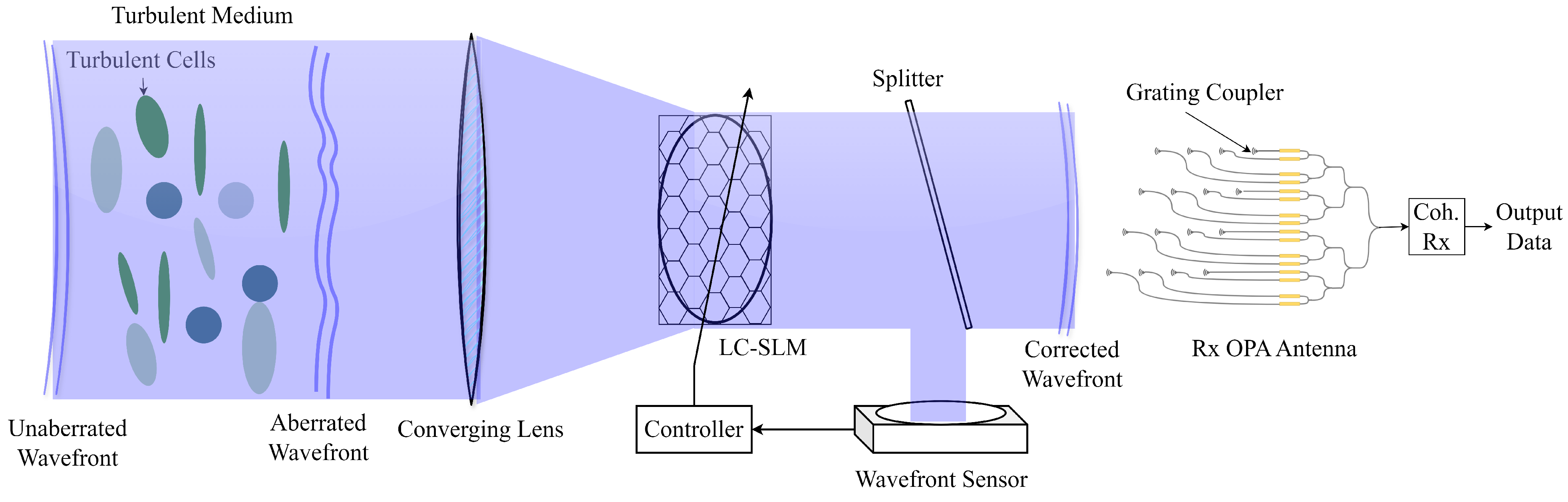
3. Proposed System Concept Architecture

3.1. PAT and Beam Divergence Control

In our previous research, we introduced an UOWC system concept using OPA antennas for electronic beam steering for PAT and beam divergence control purposes [8]. The system enables bidirectional communication between underwater vehicles whose transmitters and receivers are not aligned along the same axis. The proposed system based on OPA antennas is able to steer a laser beam electronically without mechanical movement, offering high precision and speed. A two-dimensional OPA antenna is designed, allowing beam steering in azimuth and elevation angles and control over the beam width. Controlling beam divergence is critical for pointing, acquisition, and communication. A wide beamwidth is advantageous for the pointing and acquisition phase, simplifying the alignment process, while a narrow beamwidth during the communication phase increases the link range and data throughput. Beam divergence control is managed by subdividing the antenna array into smaller subarrays, as suggested in prior work. Each subarray steers the beam to a slightly different angle, broadening the overall beam. This method allows for controlled beam divergence by manipulating angular displacements.
The mathematical foundation for OPA operation is based on Fraunhofer diffraction theory, where the far-field radiation pattern is the sum of the radiated field by each antenna element:
E ( θ , ϕ ) = n = 1 N m = 1 M E n , m ( θ , ϕ ) = 0 2 π 0 π A F ( θ 0 , ϕ 0 ) E i ( θ , ϕ ) d θ d ϕ .
A F ( θ 0 , ϕ 0 ) is the array factor for the desired angle ( θ 0 , ϕ 0 ) , and E i , j ( θ , ϕ ) is the transmitted field by a single antenna element. By adjusting the phase shifts between the antenna elements, we can control the angle at which the radiation from the antenna elements constructively interferes in order to achieve the highest directivity in the desired direction [8].
The link budget calculation for the UOWC system using the proposed OPA transceiver system, considering only attenuation due to absorption and scattering (excluding turbulence), can be expressed using Beer–Lambert’s law, as follows:
P r = P t η MZM η t D t η r D r λ 4 π L 2 e c ( λ ) · L ,
where P r is the received power, P t is the transmit power, η MZM is the efficiency of the Mach–Zehnder modulator, η t and η r are the efficiencies of the transmitter and receiver, respectively, D t and D r are the directivities of the transmitter and receiver, respectively. The term λ 4 π L 2 corresponds to the path loss of a spherical wave that has traveled a distance L. Parameter values were selected according to Table 1 in the numerical evaluation for link budget calculation.
The system concept employs a continuous-wave (CW) laser as the light source, modulated using an IQ Mach–Zehnder Modulator (MZM) for complex-valued modulation. For OPA antenna design at the transmitter and receiver side, photonic integrated circuits (PICs) on a silicon waveguide platform with λ / 2 -pitch are assumed, as suggested in [26], employing 3 dB splitters, phase shifters, and grating couplers.

3.2. Turbulence Compensation

Turbulence in underwater environments can cause significant fluctuations in the refractive index, leading to beam scintillation and degradation of communication link performance. To maintain error-free communication, compensating for turbulence effects is crucial. Turbulence degrades our UOWC system in two significant ways. Firstly, turbulence reduces the received signal intensity, directly affecting communication performance. Secondly, it causes errors in the angle of arrival (AoA) estimation for the PAT system. Given that the aperture size of the assumed ( 16 × 16 ) OPA system on the photonics integrated circuit is only 3.6   μ m 2 [8], it can be considered as a point receiver. Even minor phase distortions in the wavefront of the incoming signal can lead to inaccurate AoA estimations. Incorrect AoA estimation results in the PAT system optimizing the antenna array gain in the wrong direction, leading to severe degradation or complete loss of the communication link.
In general, there are three methods that can be used to compensate for the turbulence: spatial diversity, aperture averaging, and adaptive optics. In the spatial diversity method, multiple transceivers are employed to mitigate the fading effect of turbulence by averaging the signals received from different spatial locations [27,28,29]. Aperture averaging involves using a larger receiver aperture to collect light over a wider area, which helps to reduce the impact of turbulence-induced intensity fluctuations by averaging out the variations in the received signal [30,31,32]. Adaptive optics use real-time phase correction of the distorted wavefront, thereby improving the quality of the received signal [33,34,35].
In addition to the electronic beam control options provided by the OPAs, we propose integrating an LC-SLM as an adaptive optics module for real-time compensation.
While it is true that conventional adaptive optics systems like deformable mirrors are designed for phase correction, LC-SLMs can be configured to modulate both phase and amplitude [36,37]. This dual modulation capability allows the LC-SLM to correct for amplitude fluctuations, helping to reduce scintillation.
In addition, we are aware of the challenges associated with implementing turbulence compensation on the receiver side. In harsh underwater environments with high absorption, scattering, and turbulence, a pre-compensation approach (on the transmitter side) is even less feasible due to the lack of a reliable feedback link for real-time correction. Therefore, our proposed system, which utilizes the LC-SLM together with aperture averaging, is well suited to these conditions.
Recent advances in LC-SLM technology have significantly improved their performance, particularly concerning bandwidth. Although traditional LC-SLMs were limited to a bandwidth of approximately 40 Hz, state-of-the-art devices now achieve bandwidths up to 120 Hz or higher [38,39,40]. For instance, commercially available high-speed LC-SLMs, such as those from Santec and Meadowlark Optics, have demonstrated refresh rates exceeding 1400 Hz due to advancements in liquid crystal response times [39]. Recent studies have also reported sub-millisecond response times and refresh rates higher than 2000 fps, enabling information bandwidths up to 190 Gb/s [41]. Additionally, LC-SLMs have been successfully characterized in adaptive optics testbeds for reproducing phase screens, demonstrating their utility in evaluating reconstruction and control algorithms [42]. Moreover, advanced calibration techniques now enable reference-free phase modulation calibration of LC-SLMs, which improves their performance and usability for high-precision applications [43]. These developments narrow the performance gap between LC-SLMs and deformable mirrors, making LC-SLMs suitable for real-time turbulence correction in dynamic environments [44] While it is true that our study focuses on the correction of only seven modes, the high spatial resolution of LC-SLMs remains advantageous. It provides flexibility for future extensions of the system, allowing adaptation to different turbulence conditions where higher-order corrections may be required. Moreover, having the capability to achieve high spatial resolution is inherently beneficial, as it allows optimization of the number of pixels according to specific system requirements rather than being constrained by hardware limitations.
This setup also includes a lens for aperture averaging, which is particularly beneficial for point receivers. Aperture averaging softens small fluctuations and ensures robust and accurate AoA estimation.
As shown in Figure 3 the incoming signal is split into two paths. One path is directed to the OPA system, while a portion of the received beam is used for feedback. This feedback beam is captured by a Shack–Hartmann wavefront sensor, which detects wavefront distortions. A Shack–Hartmann wavefront sensor is an element that is frequently used in adaptive optics systems for detecting wavefront distortions [45]. The detected wavefront is then decomposed into Zernike polynomials to estimate the aberrations. The controller uses this information to generate a control signal that is sent to the LC-SLM. The LC-SLM consists of a liquid crystal layer whose refractive index can be adjusted by applying varying electrical voltages. By controlling the voltages across the array of liquid crystal pixels, the phase of the incoming beam is modulated to counteract the effects of turbulence. Through this feedback loop, the LC-SLM adjusts its phase pattern to correct for the observed distortions.
The method of adaptive optics and aperture averaging proposed for the system is explained in more detail below.

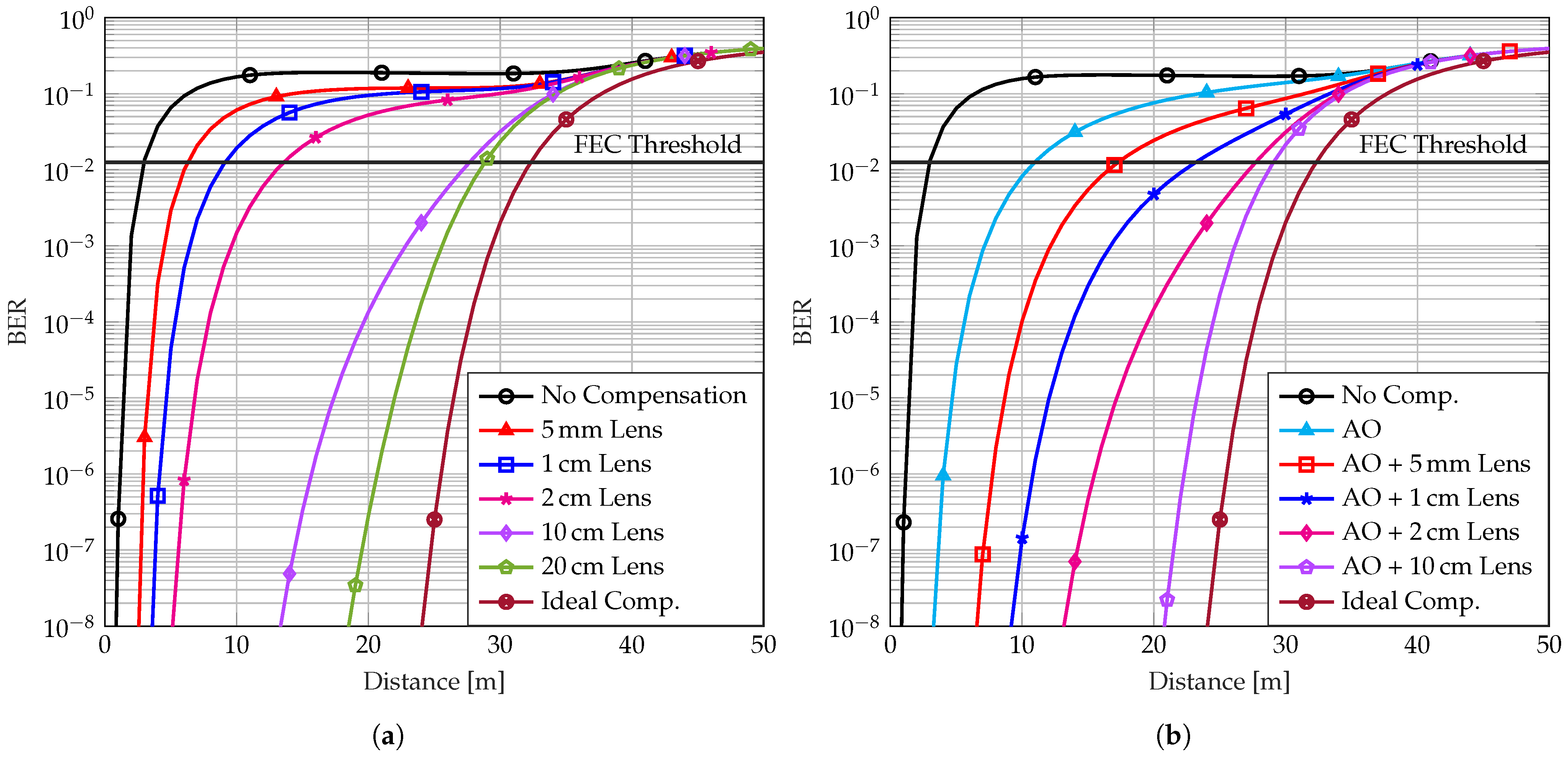
3.2.1. Adaptive Optics

In adaptive optics, a device is used to reverse the distortions caused by turbulence. The deformable mirror (DM) is typically used for this purpose. In our research, we propose using LC-SLM. The key advantage of LC-SLMs lies in their high spatial resolution, which allows precise correction of fine-scale phase distortions [38]. This capability is critical in underwater optical systems, where complex turbulence-induced aberrations can significantly impact performance. Furthermore, LC-SLMs have been integrated with advanced Shack–Hartmann wavefront sensors, replacing traditional microlens arrays with programmable Fresnel lenses to enhance spatial resolution and dynamic range [39]. Moreover, unlike deformable mirrors, LC-SLMs operate entirely in the electrical domain, eliminating the need for mechanical changes [44]. This not only simplifies the system design but also enhances reliability and reduces the potential for mechanical failures. The absence of moving parts in LC-SLMs contributes to their durability and stability, particularly in environments where mechanical vibrations or stresses could impair performance.
LC-SLM is controlled by a feedback loop containing a wavefront sensor and a controller. For several decades, the Shack–Hartmann wavefront sensor has been used in adaptive optics to detect and correct optical aberrations. This sensor uses a micro-lens array to split the incident light into smaller segments and focus each one onto a two-dimensional camera. The resulting pattern of focal points provides important information about the local wavefront inclination at each microlens. If the incoming wavefront is distorted, these spots will shift from their expected positions. By calculating the displacement of each spot relative to an ideal, aberration-free reference, the average wavefront slopes can be determined. Once these local slopes are measured, they are processed using a wavefront reconstruction algorithm, such as the modal or zonal approach, to determine the overall shape of the wavefront. This reconstructed wavefront provides a detailed map of the optical aberrations present in the system [46,47].
The turbulence distortion can be expanded into Zernike polynomials, which are a set of basis functions. Zernike polynomials are among the most well-known and widely used functions in the adaptive optics field. The more Zernike modes can be removed by the adaptive optics system, the better the turbulence can be compensated and the better the communication performance [48,49]. An adaptive optics system can be described mathematically by a filter function, which represents the removal of the spatial modes by the phase conjugation method. The filter function is derived from the Fourier transform of Zernike polynomials and is given by
F even m , n ( γ κ , D , ϕ ) = 2 ( n + 1 ) 2 J n + 1 ( γ κ D / 2 ) γ κ D / 2 2 cos 2 ( m ϕ ) ,
F odd m , n ( γ κ , D , ϕ ) = 2 ( n + 1 ) 2 J n + 1 ( γ κ D / 2 ) γ κ D / 2 2 sin 2 ( m ϕ ) ,
F m = 0 , n ( γ κ , D , ϕ ) = 2 ( n + 1 ) 2 J n + 1 ( γ κ D / 2 ) γ κ D / 2 2 ,
where D is the receiver aperture diameter and J n + 1 ( ) are Bessel functions of the first order [24]. The parameter γ is given by
γ = 1 Θ + i Δ ( 1 z / L ) ,
with a special case involving a spherical wave Θ = 1 and Δ = 0 . To integrate the effects of adaptive optics into our turbulence model, we modify the turbulence power spectrum by introducing the adaptive optics filter function. We define the corrected power spectrum as
Φ new ( κ ) = Φ old ( κ ) · 0 2 π [ 1 m , n F m , n γ κ , D , ϕ ] d ϕ .
This expression is then applied to Equation (6) to recalculate the refractive index structure function. Using the updated structure function C n , we compute the Rytov variance, σ R 2 . Finally, by applying the new Rytov variance into Equation (8), the scintillation index is derived.
In this work, we focus on removing the first seven low-order Zernike modes, namely piston ( n = 0 , m = 0 ) , tilt ( n = 1 , m = ± 1 ) , defocus ( n = 2 , m = 0 ) , astigmatism ( n = 2 , m = ± 2 ) , coma ( n = 3 , m = ± 1 ) , trefoil ( n = 3 , m = ± 3 ) , and spherical ( n = 4 , m = 0 ) . Because each pair ± m merges into a single term after integration in ϕ , these seven modes correspond to a total of 11 distinct Zernike polynomials. When summing only the modes listed above, the ϕ -integration yields a closed-form expression. Defining r = γ κ D / 2 , the integral becomes
0 2 π 1 F piston F tilt ± d ϕ = 2 π 2 π J 1 ( r ) r 2 8 π J 2 ( r ) r 2 18 π J 3 ( r ) r 2 32 π J 4 ( r ) r 2 10 π J 5 ( r ) r 2 .
The scintillation indices for varying ratios of temperature to salinity fluctuation before and after compensation with adaptive optics are shown in Figure 4. It demonstrates the effectiveness of the scintillation index reduction.

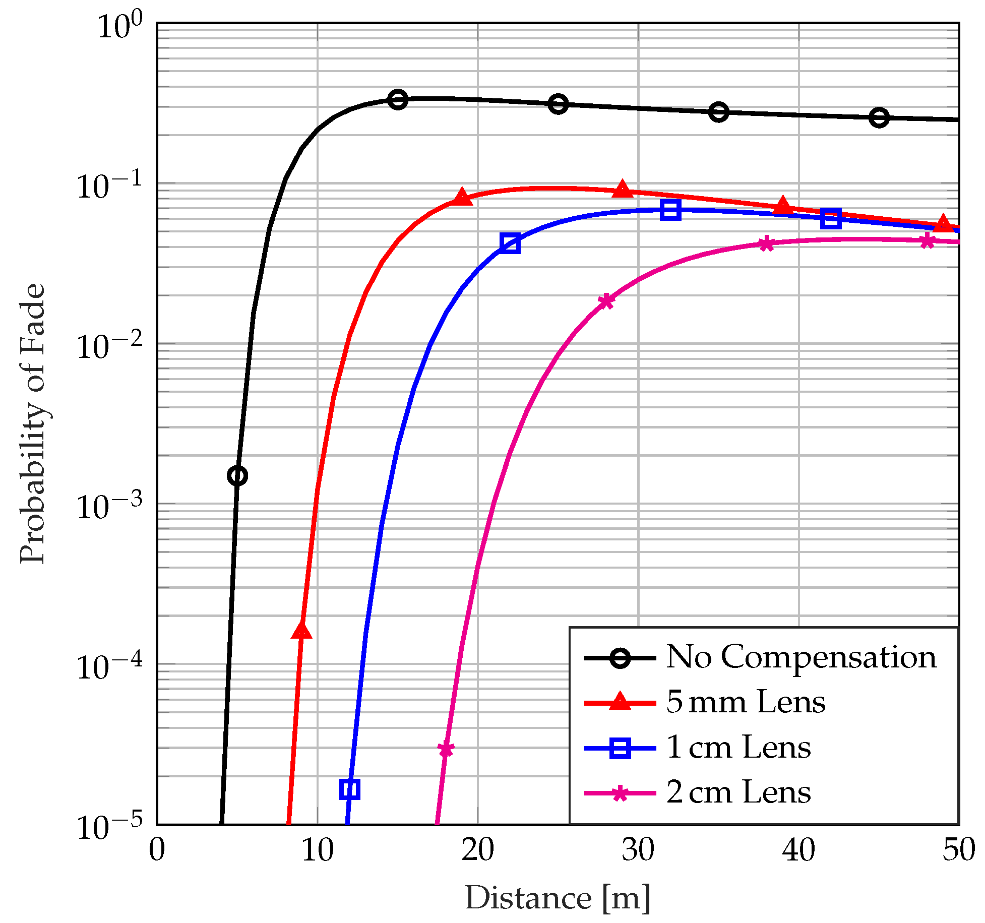
3.2.2. Aperture Averaging

If the receiving aperture is smaller than the correlation width of the irradiance fluctuations, it can be considered a point receiver. However, when the aperture size exceeds this correlation width, it observes multiple fluctuations. As a result, these fluctuations are averaged out by the larger aperture. This leads to a reduction in scintillation called aperture averaging. Aperture averaging changes the frequency content of irradiance fluctuations. Studies have shown that aperture averaging shifts the power concentration of scintillation from higher to lower frequencies, averaging out the fastest fluctuations in the irradiance power spectrum. This reduces high-frequency turbulence effects, as small-scale fluctuations that contribute to rapid intensity fluctuations are suppressed. In addition, it has been shown that the spatial frequency content of the irradiance is shifted by aperture averaging, as the fluctuations caused by small-scale turbulence structures are averaged over the aperture. As a result, the scintillation measured by a receiving aperture is mainly influenced by large-scale turbulence effects. Thus, with a larger aperture, the scintillation is due to slower, larger-scale variations, making the system less sensitive to rapid irradiance fluctuations [23,32,50]. The scintillation index of a spherical wave after aperture averaging with a lens with a diameter D is derived in [50] as follows:
σ I , s p 2 ( D ) = exp 0.196 σ R 2 ( 1 + 0.18 d 2 + 0.186 σ R 12 / 5 ) 7 / 6 + 0.204 σ R 2 ( 1 + 0.23 σ R 12 / 5 ) 5 / 6 1 + 0.9 d 2 + 0.207 d 2 σ R 12 / 5 1 ,
where d = k D 2 4 L . Without a lens ( D = 0 ) , Equation (18) is a minor variation of Equation (8), which is the scintillation index of a point receiver. The scintillation indices for varying temperature to salinity fluctuation ratios before and after compensation with aperture averaging are shown in Figure 5a.
Figure 5b illustrates how aperture averaging significantly reduces the scintillation index at different turbulence strengths. Note that the minimum value of the lens diameter corresponds to the receiver aperture size without any lens. Aperture averaging even with a small lens drastically reduces the scintillation index. For instance, for D = 5 cm the scintillation indices are 2.4 × 10 2 , 4.4 × 10 3 , and 3.6 × 10 4 for strong, moderate, and weak turbulence strengths, respectively. In all these three cases, the scintillation index is negligible, whereas without aperture averaging, the scintillation indices are 2.31 , 1.36 , and 0.12 , respectively.

4. Numerical Results, Evaluations, and Discussion

In this section, we present the numerical results and evaluations of our proposed UOWC system concept by analyzing the probability of fade and the bit error rate (BER), which are important performance measures for communication systems.
For numerical evaluations, the system parameters used in the simulations are listed in Table 1. For underwater optical channel modeling, we consider clean ocean water with an attenuation coefficient of c = 0.151 m 1 . The turbulence strength is varied by adjusting the temperature-to-salinity fluctuation ratio w to represent weak, moderate, and strong turbulence conditions. The transceiver setup includes a ( 16 × 16 ) OPA antenna for electronic beam steering, an LC-SLM with a 4 mm aperture for adaptive optics, and a converging lens for aperture averaging. The optical carrier operates at 600 THz with a transmitted power of 10 mW ( 10 dBm ).
The probability of fade is the percentage of time for which the received irradiance is below a certain threshold:
P ( I I t h ) = 0 I t h p I ( I ) d I .
The substitution of Equation (10) in Equation (19) leads to
P ( I I t h ) = 1 2 1 + erfc 0.5 σ I 2 + ln I t h I 2 σ I 2 ,
where erfc ( ) is the error function and I is the on-axis mean irradiance.
In the literature, a fading threshold parameter F t h is defined, which determines the dB level below the mean on-axis irradiance, at which the threshold I t h is established [51]:
F t h = 10 log 10 ( I / I t h ) .
The substitution of Equation (21) in Equation (20) leads to
P ( I I t h ) = 1 2 1 + erfc 0.5 σ I 2 0.23 F t h 2 σ I 2 .
In Figure 6 we present the probability of fade corresponding to our proposed system under clean ocean conditions for different aperture averaging lens diameters. A rapid increase in the probability of fade is evident when turbulence is not compensated, with P t h exceeding 0.1 within a distance of 10 m. Notably, at shorter distances, the lens diameter significantly influences the probability of fade, demonstrating that larger lenses provide greater mitigation through aperture averaging. However, at longer distances, the probability of fade converges across all lens diameters, indicating diminishing returns from increasing lens size. It is also noticeable that at shorter distances, the lens diameter becomes more important and the influence of aperture averaging is more pronounced with larger lenses, but at greater distances, the probability of fading converges for all lens diameters.
Assuming binary phase shift keying (BPSK), the BER can be determined using the following equation [52,53]:
BER BPSK = 0 p I ( I ) Q SNR d I ,
where p I ( I ) is the probability density function of the irradiance fluctuation described in Equation (10). The function Q ( ) is the tail distribution function of a probability distribution. The average signal-to-noise ratio SNR in a shot-noise limited system can be expressed by [23]
SNR = SNR 0 1 + σ I , s p 2 SNR 0 2 ,
where SNR 0 is the signal-to-noise ratio in the absence of turbulence.
As shown in Figure 7, SNR cannot increase to the same rate as SNR 0 . As the scintillation index increases, it results in a saturation effect where an increase in the transmit power does not lead to a corresponding rise in SNR .
The BER curves in Figure 8 illustrate the performance of the UOWC system with adaptive optics for different lens diameters cascaded with our proposed ( 16 × 16 ) OPA antenna in [8] in a clean ocean scenario. The BER curves show that with adaptive optics, we can increase the communication reach by almost three times compared to the uncompensated scenario. A soft-decision forward error correction (SD-FEC) code with an overhead of 15.8 % can reach an FEC threshold of 1.25 × 10 2 . The compensation methods demonstrate that this improvement in BER allows for a greater operational range while staying within the FEC threshold, thereby enhancing the overall system effectiveness. However, the benefits of increasing the lens size diminish beyond a certain point, so a trade-off between performance enhancement and the receiver size and weight should be found for practical implementations. By comparing (a) and (b) in Figure 8, we can see that it is possible to use either a larger lens without an LC-SLM or a smaller lens with an LC-SLM.

5. Conclusions

Our system concept addresses the significant challenges in UOWC caused by turbulence, which can drastically affect communication performance. By employing the adaptive optics technique based on LC-SLM phase correction, we compensate for the effects of turbulence, leading to improved BER and overall system reliability. The combination of aperture averaging and adaptive optics is effective because each technique addresses different aspects of turbulence compensation. Aperture averaging works by averaging out faster fluctuations, effectively smoothening rapid changes that the adaptive optics system cannot respond to quickly enough due to the inherent delays in real-time feedback loops. This averaging process helps stabilize the signal, reducing the impact of high-frequency turbulence. On the other hand, adaptive optics provide real-time compensation for more gradual distortions by using a feedback control loop. This dynamic adjustment enhances the robustness of the system by correcting phase distortions that aperture averaging alone cannot handle. Together, aperture averaging and adaptive optics create a complementary system where aperture averaging shifts the power concentration of scintillation from higher to lower frequencies, averaging out the fastest fluctuations in the irradiance power spectrum [32,50], and adaptive optics correct the lower-frequency distortions, resulting in improved overall performance and reliability. This turbulence compensation technique increases the communication reach, particularly in environments with stronger turbulence. The combination of OPAs for precise beam steering and LC-SLMs for turbulence compensation represents a significant advancement in the development of high-performance UOWC systems. Our numerical results confirm the effectiveness of the proposed system. Future work will focus on experimental verification and further optimization of the system to fully realize its potential for UOWC applications. By combining LC-SLM based adaptive optics and aperture averaging, the system achieves a scintillation index reduction of over 90%, leading to a threefold extension in achievable link distance under strong turbulence conditions. Moreover, at a link distance of 20 m, the BER improves by up to two orders of magnitude compared to a baseline system without turbulence compensation. Our numerical results confirm that the proposed system significantly enhances communication performance under underwater turbulence.

Author Contributions

Conceptualization and methodology, A.D. and S.P.; writing—draft preparation, A.D.; writing—review and editing, A.D., P.A.H. and S.P.; supervision and funding acquisition, S.P. and P.A.H. All authors have read and agreed to the published version of the manuscript.

Funding

This research received no external funding.

Institutional Review Board Statement

Not applicable.

Informed Consent Statement

Not applicable.

Data Availability Statement

The original contributions presented in this study are included in the article. Further inquiries can be directed to the corresponding author.

Conflicts of Interest

The authors declare no conflicts of interest.

References

  1. Hoeher, P.A.; Sticklus, J.; Harlakin, A. Underwater Optical Wireless Communications in Swarm Robotics: A Tutorial. IEEE Commun. Surv. Tutor. 2021, 23, 2630–2659. [Google Scholar] [CrossRef]
  2. Abdelfatah, R.; Alshaer, N.; Ismail, T. A review on pointing, acquisition, and tracking approaches in UAV-based FSO communication systems. Opt. Quantum Electron. 2022, 54, 571. [Google Scholar] [CrossRef]
  3. Kaymak, Y.; Rojas-Cessa, R.; Feng, J.; Ansari, N.; Zhou, M.; Zhang, T. A survey on acquisition, tracking, and pointing mechanisms for mobile free-space optical communications. IEEE Commun. Surv. Tutor. 2018, 20, 1104–1123. [Google Scholar] [CrossRef]
  4. Zhang, Q.; Yue, D.; Xu, X. Generalized transmit laser selection for vertical underwater wireless optical communications over Gamma-Gamma turbulence channels. Opt. Express 2023, 31, 37943–37958. [Google Scholar] [CrossRef]
  5. Palitharathna, K.W.S.; Suraweera, H.A.; Godaliyadda, R.I.; Herath, V.R.; Thompson, J.S. Average rate analysis of cooperative NOMA aided underwater optical wireless systems. IEEE Open J. Commun. Soc. 2021, 2, 2292–2310. [Google Scholar] [CrossRef]
  6. Kaushal, H.; Kaddoum, G. Underwater optical wireless communication. IEEE Access 2016, 4, 1518–1547. [Google Scholar] [CrossRef]
  7. Mobley, C. Light and Water; Academic Press: Cambridge, MA, USA; Elsevier Science: Amsterdam, The Netherlands, 1994. [Google Scholar]
  8. Derakhshandeh, A.; Pachnicke, S.; Hoeher, P.A. Underwater Wireless Laser-Based Communications Using Optical Phased Array Antennas. IEEE Photonics J. 2023, 15, 1–9. [Google Scholar] [CrossRef]
  9. Xu, L.; Li, K.; Zhang, G.; Yang, J.; Yin, Z.; Zhong, M.; Lu, H.; Deng, G.; Li, Y. Fully Electrically Driven Liquid Crystal Reconfigurable Intelligent Surface for Terahertz Beam Steering. IEEE Trans. Terahertz Sci. Technol. 2024, 14, 708–717. [Google Scholar] [CrossRef]
  10. Ndjiongue, A.R.; Ngatched, T.M.N.; Dobre, O.A.; Haas, H. Re-configurable intelligent surface-based VLC receivers using tunable liquid-crystals: The concept. J. Lightw. Technol. 2021, 39, 3193–3200. [Google Scholar] [CrossRef]
  11. Aboagye, S.; Ngatched, T.M.N.; Ndjiongue, A.R.; Dobre, O.A.; Shin, H. Liquid crystal-based RIS for VLC transmitters: Performance analysis, challenges, and opportunities. IEEE Wireless Commun. 2023, 31, 98–105. [Google Scholar] [CrossRef]
  12. Toselli, I.; Gladysz, S. Improving system performance by using adaptive optics and aperture averaging for laser communications in oceanic turbulence. Opt. Express 2020, 28, 17347–17361. [Google Scholar] [CrossRef] [PubMed]
  13. Zeng, Z.; Fu, S.; Zhang, H.; Dong, Y.; Cheng, J. A Survey of Underwater Optical Wireless Communications. IEEE Commun. Surv. Tutor. 2016, 19, 204–238. [Google Scholar] [CrossRef]
  14. Fletcher, A.S.; Hamilton, S.A.; Moores, J.D. Undersea laser communication with narrow beams. IEEE Commun. Mag. 2015, 53, 49–55. [Google Scholar] [CrossRef]
  15. Hill, R.J. Optical propagation in turbulent water. J. Opt. Soc. Am. 1978, 68, 1067–1072. [Google Scholar] [CrossRef]
  16. Nikishov, V.V.; Nikishov, V.I. Spectrum of turbulent fluctuations of the sea-water refraction index. Int. J. Fluid Mech. Res. 2000, 27, 1. [Google Scholar] [CrossRef]
  17. Korotkova, O.; Farwell, N.; Shchepakina, E. Light scintillation in oceanic turbulence. Waves Random Complex Media 2012, 22, 260–266. [Google Scholar] [CrossRef]
  18. Ata, Y.; Kiasaleh, K. Analysis of optical wireless communication links in turbulent underwater channels with wide range of water parameters. IEEE Trans. Veh. Technol. 2023, 72, 6363–6374. [Google Scholar] [CrossRef]
  19. Yao, J.-R.; Elamassie, M.; Korotkova, O. Spatial power spectrum of natural water turbulence with any average temperature, salinity concentration, and light wavelength. J. Opt. Soc. Am. A 2020, 37, 1614–1621. [Google Scholar] [CrossRef]
  20. Baykal, Y. Scintillation index in strong oceanic turbulence. Opt. Commun. 2016, 375, 15–18. [Google Scholar] [CrossRef]
  21. Luan, X.; Yue, P.; Yi, X. Scintillation index of an optical wave propagating through moderate-to-strong oceanic turbulence. J. Opt. Soc. Am. A 2019, 36, 2048–2059. [Google Scholar] [CrossRef]
  22. Deng, P.; Yuan, X.-H.; Huang, D. Scintillation of a laser beam propagation through non-Kolmogorov strong turbulence. Opt. Commun. 2012, 285, 880–887. [Google Scholar] [CrossRef]
  23. Andrews, L.C.; Phillips, R.L. Laser Beam Propagation Through Random Media, 2nd ed.; CRC Press: Boca Raton, FL, USA, 2005. [Google Scholar]
  24. Tyson, R.K.; Frazier, B.W. Principles of Adaptive Optics; CRC Press: Boca Raton, FL, USA, 2022. [Google Scholar]
  25. Andrews, L.C.; Phillips, R.L.; Hopen, C.Y.; Al-Habash, M.A. Theory of optical scintillation. J. Opt. Soc. Am. A 1999, 16, 1417–1429. [Google Scholar] [CrossRef]
  26. Sharma, A.; Straguzzi, J.N.; Xue, T.; Govdeli, A.; Chen, F.D.; Stalmashonak, A.; Sacher, W.D.; Poon, J.K. Crosstalk-Compensated Optical Phased Arrays for Wide-Angle Beam-Steering. In Proceedings of the Optical Fiber Communication Conference, San Diego, CA, USA, 24–28 March 2024. Th2A.3. [Google Scholar]
  27. Huang, A.; Tao, L.; Wang, C.; Zhang, L. Error performance of underwater wireless optical communications with spatial diversity under turbulence channels. Appl. Opt. 2018, 57, 7600–7608. [Google Scholar] [CrossRef] [PubMed]
  28. Peppas, K.P.; Boucouvalas, A.C.; Ghassemlooy, Z. Performance of underwater optical wireless communication with multi-pulse pulse-position modulation receivers and spatial diversity. IET Optoelectron. 2017, 11, 180–185. [Google Scholar] [CrossRef]
  29. Liu, J.; Li, Y.; Yang, R.; Pan, Z.; Zou, F.; Li, Z.; Geng, C.; Li, X. Performance optimization of spatial diversity antenna using hybrid combination for terrestrial optical wireless communication. Opt. Commun. 2024, 555, 130228. [Google Scholar] [CrossRef]
  30. Fu, Y.; Huang, C.; Du, Y. Effect of aperture averaging on mean bit error rate for UWOC system over moderate to strong oceanic turbulence. Opt. Commun. 2019, 451, 6–12. [Google Scholar] [CrossRef]
  31. Eso, E.; Ghassemlooy, Z.; Zvanovec, S.; Sathian, J.; Abadi, M.M.; Younus, O.I. Performance of vehicular visible light communications under the effects of atmospheric turbulence with aperture averaging. Sensors 2021, 21, 2751. [Google Scholar] [CrossRef]
  32. Vetelino, F.S.; Young, C.; Andrews, L.; Recolons, J. Aperture averaging effects on the probability density of irradiance fluctuations in moderate-to-strong turbulence. Appl. Opt. 2007, 46, 2099–2108. [Google Scholar]
  33. Shaffer, B.D.; Vorenberg, J.R.; Wilcox, C.C.; McDaniel, A.J. Generalizable turbulent flow forecasting for adaptive optics control. Appl. Opt. 2023, 62, G1–G11. [Google Scholar] [CrossRef]
  34. Soloviev, A.A.; Kotov, A.V.; Perevalov, S.E.; Esyunin, M.V.; Starodubtsev, M.V.; Alexandrov, A.G.; Galaktionov, I.V.; Samarkin, V.V.; Kudryashov, A.V.; Ginzburg, V.N.; et al. Adaptive system for wavefront correction of the PEARL laser facility. Quantum Electron. 2020, 50, 1115. [Google Scholar] [CrossRef]
  35. Galaktionov, I.; Sheldakova, J.; Samarkin, V.; Toporovsky, V.; Kudryashov, A. Atmospheric turbulence with Kolmogorov spectra: Software simulation, real-time reconstruction and compensation by means of adaptive optical system with bimorph and stacked-actuator deformable mirrors. Photonics 2023, 10, 1147. [Google Scholar] [CrossRef]
  36. Yoon, M.S.; Oh, K.-J.; Choo, H.-G.; Kim, J. A spatial light modulating LC device applicable to amplitude-modulated holographic mobile devices. In Proceedings of the 2015 IEEE 13th International Conference on Industrial Informatics (INDIN), Cambridge, UK, 22–24 July 2015; pp. 677–681. [Google Scholar] [CrossRef]
  37. Wang, M.; Zong, L.; Mao, L.; Marquez, A.; Ye, Y.; Zhao, H.; Vaquero Caballero, F.J. LCoS SLM study and its application in wavelength selective switch. Photonics 2017, 4, 22. [Google Scholar] [CrossRef]
  38. Kong, N.; Li, C.; Xia, M.; Li, D.; Qi, Y.; Xuan, L. Optimization of the open-loop liquid crystal adaptive optics retinal imaging system. J. Biomed. Opt. 2012, 17, 026001. [Google Scholar]
  39. Zhang, F.; Shen, H.; Sun, Y. Shack-Hartmann wavefront sensor based on a two-dimensional mixed aperture diffractive lens array. Opt. Lett. 2024, 49, 522–530. [Google Scholar] [CrossRef]
  40. Cai, D.; Ling, N.; Jiang, W. Performances of liquid crystal spatial light modulator (LC-SLM) as a wave-front corrector for atmospheric turbulence compensation. Proc. SPIE 2006, 6457, 64570P. [Google Scholar]
  41. Pivnenko, M.; Li, K.; Chu, D. Sub-millisecond switching of multi-level liquid crystal on silicon spatial light modulators for increased information bandwidth. Opt. Express 2021, 29, 24614–24627. [Google Scholar] [CrossRef]
  42. Bellone de Grecis, E.; Rouquette, P. Characterization of a spatial light modulator for MORFEO and HARMONI adaptive optics test devices. Proc. SPIE 2024, 13097, 130975D. [Google Scholar] [CrossRef]
  43. Liu, X.; Li, J.; Yang, Y. Reference-free calibration for liquid crystal spatial light modulators: High-resolution phase-only modulation. Opt. Express 2024, 32, 30724–30737. [Google Scholar]
  44. Daly, J.T.; Pezzaniti, J.L.; Riza, N.A. Wavefront control with a spatial light modulator containing dual-frequency liquid crystal. Proc. SPIE 2004, 5553, 1–8. [Google Scholar]
  45. Aghajani, A.; Kashani, F.D.; Yousefi, M. Laboratory study of aberration calculation in underwater turbulence using Shack-Hartmann wavefront sensor and Zernike polynomials. Opt. Express 2024, 32, 15978–15992. [Google Scholar] [CrossRef]
  46. Hu, L.; Hu, S.; Gong, W.; Si, K. Learning-based Shack-Hartmann wavefront sensor for high-order aberration detection. Opt. Express 2019, 27, 33504–33517. [Google Scholar] [CrossRef] [PubMed]
  47. Hu, L.; Hu, S.; Gong, W.; Si, K. Deep learning assisted Shack-Hartmann wavefront sensor for direct wavefront detection. Opt. Lett. 2020, 45, 3741–3744. [Google Scholar] [CrossRef] [PubMed]
  48. Wang, J.Y.; Markey, J.K. Modal compensation of atmospheric turbulence phase distortion. JOSA 1978, 68, 78–87. [Google Scholar] [CrossRef]
  49. Tyson, R.K. Bit-error rate for free-space adaptive optics laser communications. JOSA A 2002, 19, 753–758. [Google Scholar] [CrossRef]
  50. Andrews, L.C.; Phillips, R.L.; Hopen, C.Y. Aperture averaging of optical scintillations: Power fluctuations and the temporal spectrum. Waves Random Media 2000, 10, 53. [Google Scholar] [CrossRef]
  51. Andrews, L.C.; Phillips, R.L.; Yu, P.T. Optical scintillations and fade statistics for a satellite-communication system. Appl. Opt. 1995, 34, 7742–7751. [Google Scholar] [CrossRef]
  52. Ghassemlooy, Z.; Popoola, W.; Rajbhandari, S. Optical Wireless Communications: System and Channel Modelling with Matlab®; CRC Press: Boca Raton, FL, USA, 2019. [Google Scholar]
  53. Gökçe, M.C.; Baykal, Y.; Ata, Y. Adaptive optics effect on performance of BPSK-SIM oceanic optical wireless communication systems with aperture averaging in weak turbulence. J. Quant. Spectrosc. Radiat. Transf. 2020, 256, 107335. [Google Scholar] [CrossRef]
Figure 1. Scintillation index vs. distance for varying ratios of temperature-to-salinity fluctuations w. The parameters for numerical simulations are taken from Table 1.
Photonics 12 00268 g001
Figure 2. PDFs of the normalized irradiance for different ratios of temperature to salinity fluctuations w over 20   m distance.
Photonics 12 00268 g002
Figure 3. System concept architecture of our proposed coherent UOWC system with cascaded aperture averaging (converging lens) and an adaptive optics system (including LC-SLM as the wavefront corrector, splitter, Shack–Hartmann wavefront sensor, and the feedback control loop) for turbulence compensation and OPA antennas for PAT. Note that the dimensions of the elements have been adjusted for clarity and are not to scale.
Photonics 12 00268 g003
Figure 4. Scintillation index reduction for varying ratios of temperature-to-salinity fluctuation w with adaptive optics. Curves marked with circles represent the uncompensated case, while those marked with squares correspond to the compensated case, where adaptive optics have been applied with the first seven Zernike modes removed.
Photonics 12 00268 g004
Figure 5. (a) Scintillation index reduction for varying ratios of temperature-to-salinity fluctuation w with a 5 c m diameter aperture averaging lens. (b) Scintillation index vs. the diameter of the aperture averaging lens for varying ratios of temperature to salinity fluctuation w for 20 m link distance.
Photonics 12 00268 g005
Figure 6. Probability of fade for varying lens sizes using the aperture averaging method, w = 0.2 , and F t h = 6 dB in the clean ocean ( c = 0.151 1 / m ).
Photonics 12 00268 g006
Figure 7. Average SNR vs. SNR 0 .
Photonics 12 00268 g007
Figure 8. BER analysis for turbulence compensation with (a) aperture averaging with different lens diameters, and (b) aperture averaging and adaptive optics with different lens diameters, cascaded with ( 16 × 16 ) OPA antenna elements in clean ocean ( c = 0.151 1 / m ), w = 0.2 .
Photonics 12 00268 g008
Table 1. Parameters used for numerical simulations.
ParameterValue
Attenuation coefficient in clean ocean c = 0.151 1 / m
LC-SLM aperture diameter D = 4 mm
LC-SLM fitting error constant α = 0.349
Rate of dissipation of turbulent kinetic energy ϵ = 10 2 m 2 / s 3
Kolmogorov microscale η = 10 2 m
Rate of dissipation of mean-square temperature χ = 10 4 K 2 / s
Carrier frequency f c = 600 THz
Laser launch power P t = 10 mW ( 10 dBm )
Insertion loss of MZM η MZM = 31.6 % ( 5 dB )
Insertion loss of OPA η Tx / Rx = 50 % ( 3 dB )
Number of OPA antenna elements ( N × M ) = ( 16 × 16 )
Transmitter and receiver antenna directivity D t / r = 28.9 dBm
Disclaimer/Publisher’s Note: The statements, opinions and data contained in all publications are solely those of the individual author(s) and contributor(s) and not of MDPI and/or the editor(s). MDPI and/or the editor(s) disclaim responsibility for any injury to people or property resulting from any ideas, methods, instructions or products referred to in the content.

