Article

Design and Processing of Hard and Self-Lubricating NiCr/hBN-cBN Composite Coatings by Laser Cladding: Investigation of Microstructure, Hardness, and Wear

Department of Advanced Materials and New Technologies, Iranian Research Organization for Science and Technology (IROST), Tehran 3313193685, Iran
*
Authors to whom correspondence should be addressed.
Photonics 2025, 12(3), 265; https://doi.org/10.3390/photonics12030265
Submission received: 3 February 2025 / Revised: 25 February 2025 / Accepted: 11 March 2025 / Published: 13 March 2025
(This article belongs to the Section Lasers, Light Sources and Sensors)

Abstract

:
Hardness and wear resistance are the requirements of nickel-based superalloys used in gas turbine blades. This study uses laser cladding technology to develop three types of wear-resistant coatings—NiCr-2%hBN, NiCr-12%cBN, and NiCr-2%hBN-12%cBN—on GTD-111 superalloy. The above coatings’ microstructure, microhardness, and tribological behavior were systematically characterized by scanning electron microscope, hardness tester, pin-on-disc wear device, and three-dimensional profiles. The hardness test results showed that the hBN coating has the lowest hardness (692 HV) due to its layered structure, and the hBN-cBN coating has the highest hardness (992 HV) due to its complex structure and the creation of inhomogeneous nucleation centers in the coating. The wear test results showed that the hBN coating has a lower coefficient of friction (COF) (0.49) than the hard cBN coating (0.53) due to its lubricating properties. Meanwhile, the wear rate of the hBN coating is lower than the wear rate of the hard cBN due to the weak forces of one in the B-N bond. However, the wear test results of hBN-cBN coating showed that the effects of hBN and the high hardness of cBN cause the formation of a coating with the lowest wear rate (0.22 × 10⁻⁶ mm3/N·m), COF (0.41), fluctuation, wear depth (17.2 µm), and wear volume loss (0.32 × 10⁵ µ3) compared to the other two coatings. In addition, in the hBN-cBN coating, due to the greater driving force for the inhomogeneous nucleation of the melt, a larger area of equiaxed grains was formed, which in turn had a significant effect on increasing the wear resistance.

1. Introduction

High-pressure turbine blades are located in the hot part of the aircraft engine and convert the gas energy from the combustion chamber into mechanical energy [1]. These blades are exposed to high temperatures, high stress, vibration effects, and centrifugal and fluid forces, which can lead to severe metallurgical damage and threaten the mechanical integrity of the parts [2]. Among the mechanisms of destruction of gas turbine blades is wear [3]. GTD-111 is one of the most prominent and newest nickel-based superalloys, which, due to its unique microstructural features, has always been considered as the rotating blades of the first row of gas turbines, which are subjected to the most severe wear damage [4]. Although the wear resistance of GTD-111 is high, critical design considerations must be considered to ensure durability and long-term performance. It has been reported that about 20–40% of the overall damage in gas turbine blades is due to wear [3]. To reduce this amount and the economic and even life effects caused by it, conventional approaches include optimization of metallurgical processes, strengthening of alloy composition components, and using surface modification techniques. Among the surface modification techniques, methods such as coating [5], thermal spraying [6], electroplating [7], and aluminide coatings [8] can be mentioned. However, there are concerns in each of the mentioned methods, which can be pointed to the problem of lack of proper adhesion of the coating to the substrate in the thermal spraying method and environmental issues in the electroplating process.
With the advent of technology, laser-based methods, including laser cladding, due to advantages such as the ability to optimize parameters, low heat, fast solidification, the ability to refine grains, flexibility in choosing the coating area, creating a strong metallurgical bond between the substrate and the coating, as well as compatibility with the environment has always been considered as one of the main methods of coating [9,10]. Laser cladding can process wear-resistant composite and cermet coatings with high speed and precision, in addition to traditional coatings [11]. By applying ZrB2/TiB2 by laser cladding, He et al. [12] processed a wear-resistant ceramic coating with needle morphology (Zrx, Tix)B2 formed through the substitution reaction of Ti and Zr atoms. The development of high entropy NiCrFeCoBx coating through laser cladding was successfully carried out by Wu et al. [13]. Their results showed that with the increase of B from 0.1 to 0.6, a complex structure of FCC1, FCC2, and MXBY phases would be formed, increasing the wear resistance by 190% and significantly contributing to grain refinement. Refinement of grains, reduction of microstructural defects, synthesis of elements, and uniformity of structure are among the things that have been reported to increase wear resistance in ceramic and metal coatings of IN718 [14], Cr3C2-Ti6Al4V [15], and Ni60-based/WC composite [16]. It has been reported that TiB2 in the TiB2/ZE41 composite inhibits fatigue crack propagation and suppresses severe delamination during wear testing [17].
By reviewing the literature, it has been determined that two methods can increase the wear resistance of coatings applied by laser cladding: first, adding self-lubricating materials such as WS2, MOS2, hexagonal boron nitride (hBN), and SiC to the composite, second, adding hard ceramic materials like WC, cubic boron nitride (cBN), TiC, and ZrB2 [18,19]. The hBN solid self-lubricating material has become a popular friction reduction additive among researchers due to its low density, outstanding automotive performance, excellent thermal stability, and good thermal conductivity [20]. Unlike MoS2 and WS2, which oxidize at high temperatures and lose their lubricating properties, hBN remains stable up to much higher temperatures [21]. MoS2 and WS2 are oxidized in oxidizing environments and high temperatures to MoO3 and WO3, which have no lubricating properties. In contrast, hBN has higher chemical stability and is less susceptible to degradation in high-temperature environments [22]. On the other hand, due to its very high hardness, cBN is considered a suitable material for resisting friction in grinding pairs. Additionally, its low density and excellent thermal properties further enhance its performance [23]. As a result, hBN and cBN improve wear resistance through two different mechanisms. In addition to hBN and cBN, other self-lubricating materials, such as graphite, metal fluorides, and novel composite lubricants, have also been explored for wear reduction [24,25]. However, hBN offers superior thermal stability compared to graphite. At the same time, cBN provides significantly higher hardness than most other solid lubricants, making them particularly effective for high-temperature and high-load applications.
In the literature, several studies have been conducted on adding hBN and cBN particles separately. After processing the CoCrFeNiTi0.8-cBN coating by laser cladding, Li et al. [26] reported that as a result of the decomposition of cBN and as a result of its synthesis with other elements, a coating rich in TiN and TiB2 particles is formed, which has a significant effect on increasing wear resistance. Kuang et al. [27] reported that the CuSn-15%hBN coating has a coefficient of friction (COF) of 0.21, and the CuSn-5%hBN coating has a COF of 0.71. However, despite the reduction of COF in the CuSn-15%hBN composite, its wear rate increased by about 8% compared to CuSn-5%hBN, which was attributed to the increase of porosity in the composite structure with the rise of hBN.
Despite numerous studies on improving the wear resistance of GTD-111 superalloy gas turbine blades, most of the research has focused on strengthening the coatings with hard and non-hard materials [28]. However, an important research gap is that the effect of simultaneously incorporating non-hard materials such as hBN and hard ceramic materials such as cBN on the microstructure and wear behavior of coatings applied to GTD-111 superalloy has not been comprehensively investigated. In this study, the focus is on creating laser coatings by combining hBN and cBN on GTD-111 superalloy as a novel method to improve the wear resistance of gas turbine blades. The interaction of these two materials in the laser cladding process and their effect on the coating microstructure and wear resistance, specifically in the field of this superalloy, has not yet been fully covered in the scientific literature. This research gap could help to understand better how these materials work in combination with each other and their impact on improving the durability and efficiency of gas turbine blades.
Briefly, cBN reduces extreme friction in the grinding pair interaction, and hBN is used as a solid lubricant in abrasive composites. On the other hand, it is expected that hBN and cBN particles, due to their hardness and high melting point as a non-homogeneous nucleating agent during laser cladding, will increase the tendency to refine grains and thus increase wear resistance. However, until now, the simultaneous effects of hBN and cBN on growing wear resistance have been less investigated. This research processed NiCr-2%hBN, NiCr-12%cBN, and NiCr-2%hBN-12%cBN coatings by laser cladding on GTD-111 superalloy. After coating, the microstructure of each layer was carefully examined and analyzed. Then, the pin-on-disc test investigated the wear behavior of each of the mentioned coatings, and the optimal sample was introduced as the most wear-resistant coating.

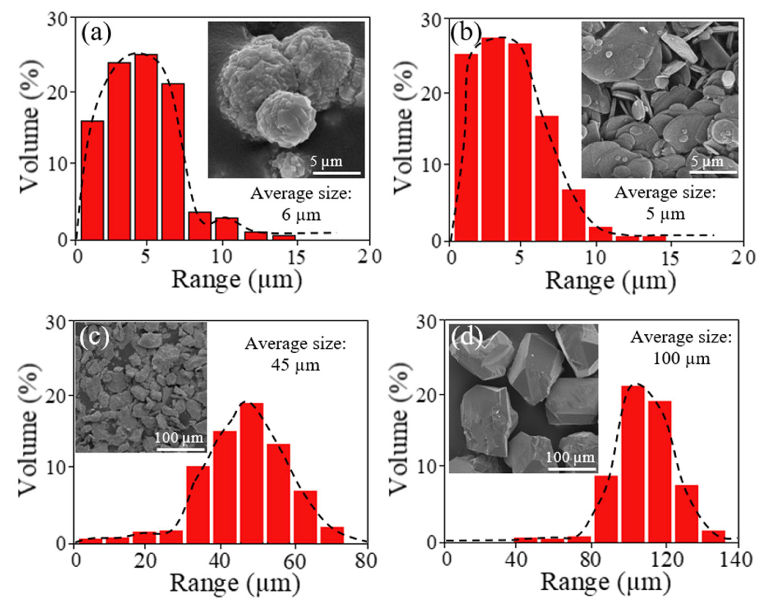
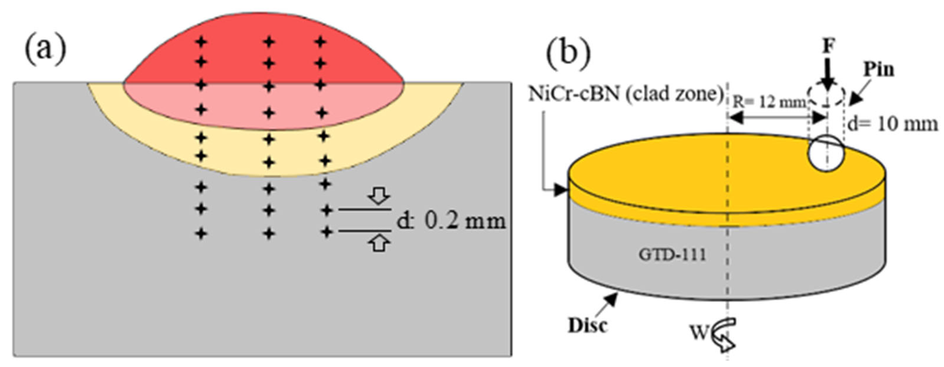
2. Materials and Methods

The design of the experiments started with selecting the substrate made of GTD-111 nickel-based superalloy in casting conditions with dimensions of 50 × 50 × 2 mm3 and the chemical composition indicated in Table 1. Before applying any coating, the surface of the substrate was cleaned with 60-grit sandpaper to ensure the absence of any pollution, such as fat, grease, oil, and oxide, and to create a substrate with high adhesion.
The material used for coating in this research was Ni and Cr metal powders and cBN and hBN non-metal powders. SEM images and distribution diagram of each powder are presented in Figure 1. In order to prepare the coating mixture, the powders were weighed with an accuracy of 0.01 g according to the ratios mentioned in Table 2. It should be noted that 12% cBN was chosen to balance between increasing hardness and preventing excessive brittleness of the coating. Also, 2% hBN was used because of its lubricating properties and to prevent excessive reduction in hardness in the coating. This combination showed the best performance in terms of hardness, reduction in friction coefficient, and wear resistance. After weighing, the powders were mixed in a mechanical mixer named Retsch PM100 high-energy planetary mixer for 15 h under Ar gas to obtain a uniform distribution of the coating material. In order to ensure the distribution of powders, XRD analysis using Cukα single-wave radiation with a wavelength of 1.542 Å was used, the result of which is shown in Figure 2. The scanning rate, scanning step size, scanning degree and range, voltage used in the device, and applied current in the XRD experiment were 1 s, 0.05 degrees, 20 to 80 degrees, 40 kV, and 30 mA, respectively.
In order to prepare the samples for coating, the coating material was combined with sodium silicate (as glue) and made into a paste. The glue was first diluted with water at a one-to-six volume ratio and then mixed with powder at a three-to-one volume ratio. After mixing and completely uniforming, this paste was drawn on superalloy samples with a thickness of 1.5 mm. A mechanical tool was used to create the uniformity of the layer, and a caliper monitored its uniformity. The laser cladding was performed by a pulsed Nd:YAG laser source model IQL-10, with a maximum power of 700 W on the preplaced layer on GTD-111. This laser can produce square pulses with a width of 2–20 ms and a frequency of 1–1000 Hz with the desired energy of up to 40 J. Table 3 shows the parameters applied to laser cladding obtained after much trial and error. The selection of laser coating parameters, particularly scan speed and pulse frequency, was based on a combination of literature review and extensive trial-and-error experiments conducted in our laboratory. Figure 3 clearly shows the schematic of the laser cladding process.
After laser cladding and to characterize the coating, the samples were cut in cross-section according to Figure 3 using a wire cutter. Then, metallographic operations were performed, including sandblasting (#100–#300) and polishing with aluminum oxide powder with a particle size of 2 µm. Microstructural studies were carried out using a field emission scanning microscope (FESEM) model MIRA3 manufactured by TESCAN company with a resolution of 1.5 nm at a voltage of 15 kV and equipped with an EDS detector. Vickers microhardness test was performed using the ASTM E92-82 standard by the Itz Wetlar hardness tester under a force of 300 g. A time of 20 s was allowed on the polished cross-sections of the samples (Figure 4a). To investigate and compare the tribological behavior of coated samples, the wear test was repeated three times at room temperature using a block ring-type dry sliding friction wear tester (MRH-5000 W) (Figure 4b). The wear test included investigation of the COF, wear volume loss, wear rate, and wear scar. The wear test parameters included friction pair Si3N4, ball diameter 10 mm, applied load 10 N, sliding time 30 min, frequency 2 Hz, and amplitude 2.5 mm. The 3D wear morphology was also obtained by Bruker Contour GT-K 3D profilometer. After the wear test, SEM images and 3D profiles were used to investigate the wear mechanism. The wear rate was calculated based on the applied load parameters (F), wear volume loss (V), and the total sliding distance (L) according to the following equation [29]:
W e a r   r a t e = V F · L

3. Results

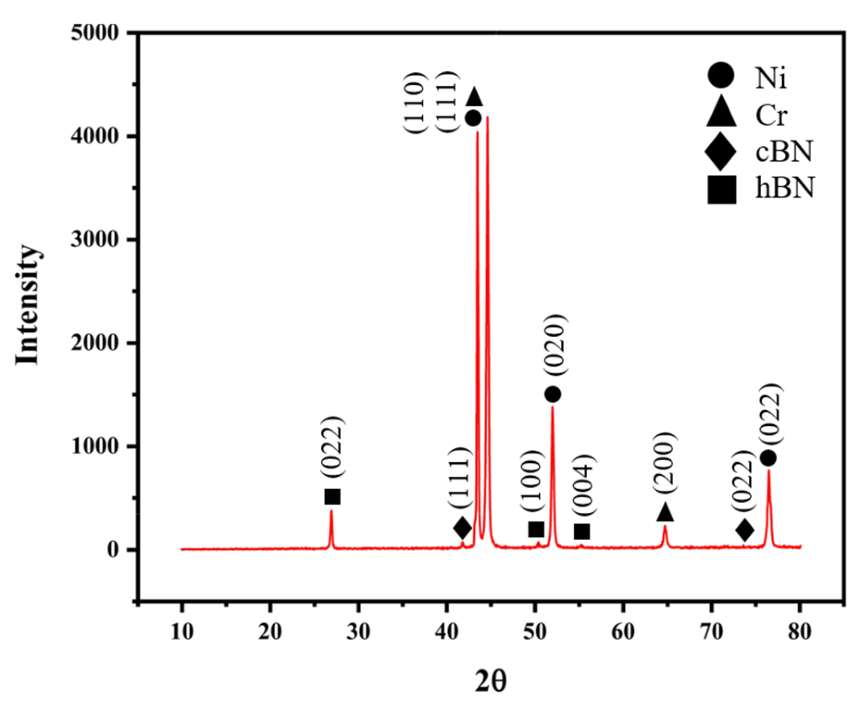
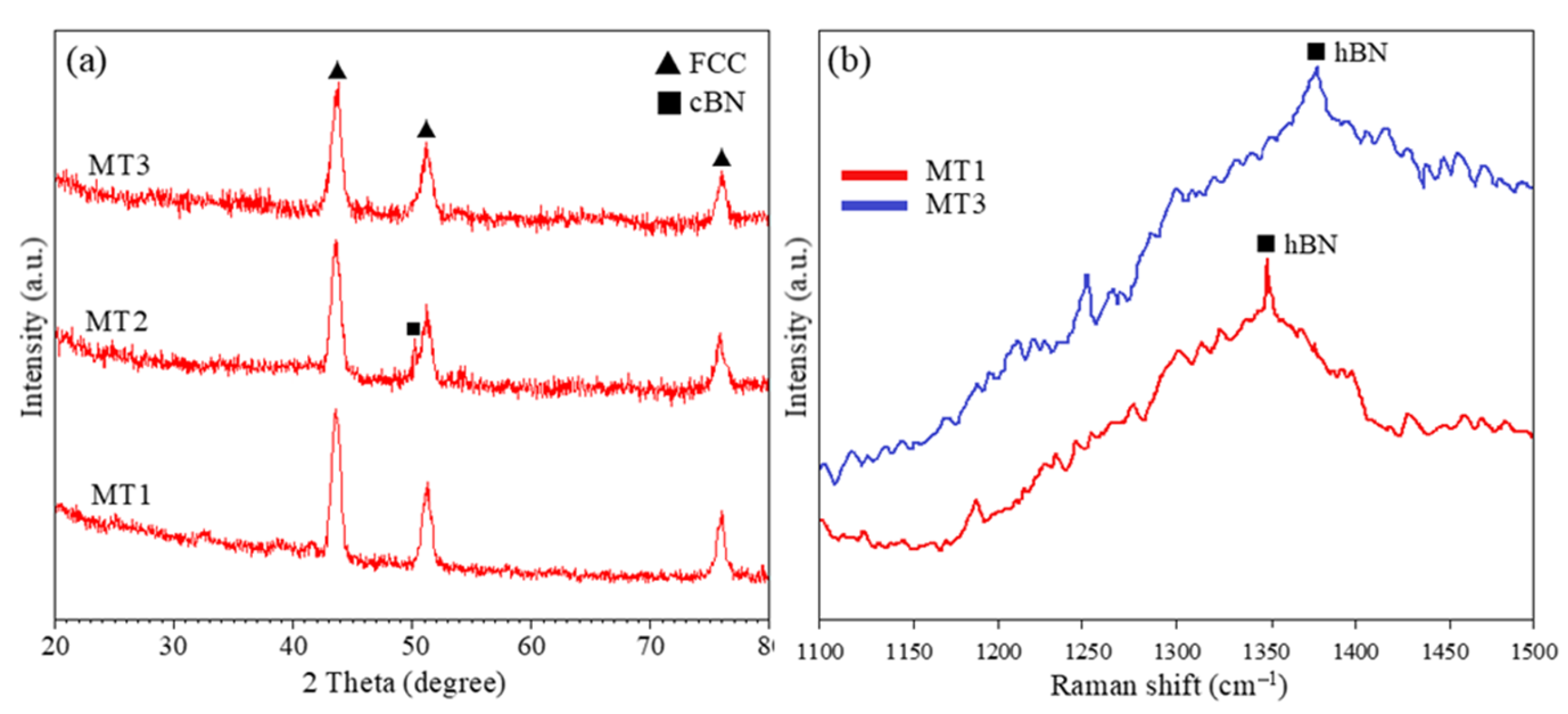
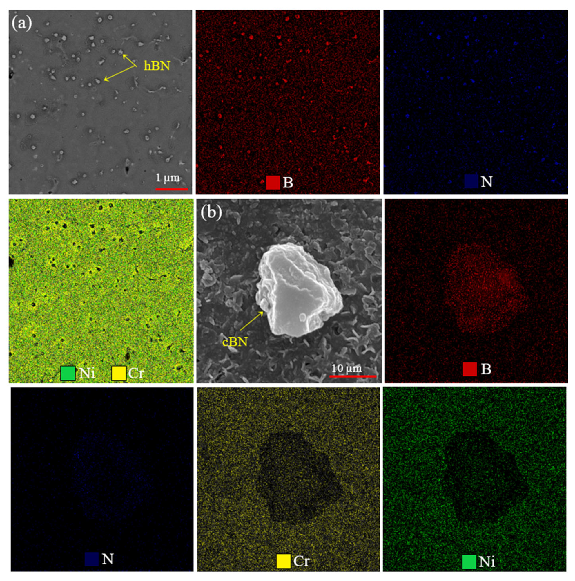
3.1. Phase Distribution

The results of phase analysis by XRD of three different samples are given in Figure 5a. As can be seen, all three coatings have FCC main phase. According to the literature, under non-equilibrium cooling conditions (such as laser cladding in this study), a Ni-Cr solid solution with an FCC structure can form [30]. As a result, distinct Ni and Cr peaks are not observed separately (see Figure 2). The peak related to the cBN phase is evident in the MT2 sample and coincides with the FCC phase in the MT3 sample. However, the peak associated with the hBN phase is not visible in MT1 and MT3 samples. The low amount and sensitivity of hBN to X-rays can be counted among the reasons for this issue. In order to increase the sensitivity of hBN against X-rays and its detection, Raman spectroscopy was used, the results of which are shown in Figure 5b. Raman spectrometry investigations showed that the Raman peaks of MT1 and MT3 samples, which correspond to hBN peaks, coincide with 1370 cm−1 and 1394 cm−1, respectively, at low frequency.

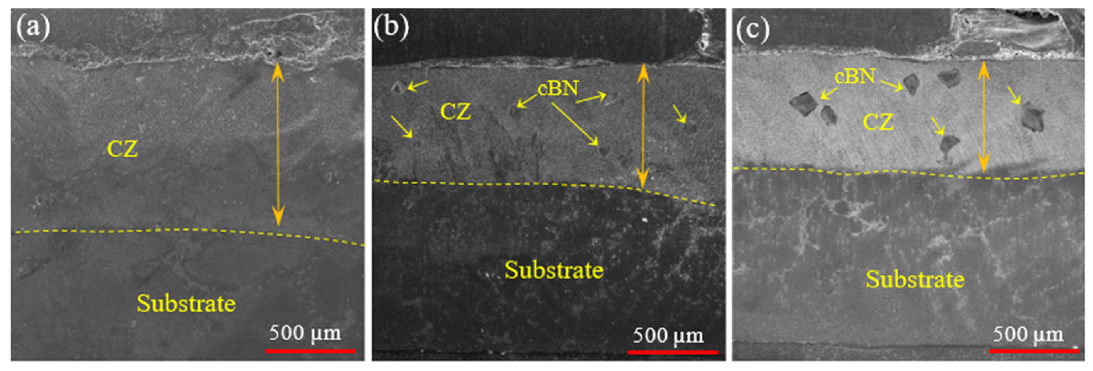
3.2. Analysis of Microstructure Morphology

The overall cross-section of the coatings of three samples in Figure 6 shows that the simultaneous presence of hBN and cBN (sample MT3) reduces the thickness of the coating. So, the thickness of MT1, MT2, and MT3 samples is 922 µm, 637 µm, and 591 µm, respectively. It is stated in the literature that adding ceramic materials to metal composites increases the density and thus reduces the thickness of the coating [31]. Microstructural studies showed that cBN particles are scattered and visible in the coating, while hBN particles are hardly visible. This is attributed to the fineness of the initial hBN particles, about 5 μm.
Figure 7 shows the changes in the morphology of dendrites during the evolution of solidification and its transformation into crystals in different samples. The energetic laser pulse influences the solidification evolution of all three coatings. So compositional subcooling occurs at the liquid-solid interface due to compositional differences. According to what is stated in the literature [32], the evolution of solidification is strongly dependent on the temperature gradient (G) and the solidification rate (R). So, G/R determines the morphology of crystal dendrites, and GR determines their size. Since R is low and G is high at the bottom of the melt pool, the G/R ratio is at its maximum value, thus increasing the tendency to form planar crystals (see Figure 7a). By moving away from the bottom of the molten pool and increasing the grain growth rate, the value of R starts to increase, and the value of G starts to decrease, which results in a decrease in G/R. Under such conditions, the liquid-solid interface becomes unstable, and the tendency to columnar crystals increases, as seen in all three coatings. Gradually, by moving away from the bottom of the molten pool and reaching the middle and top of the molten pool, there is an increase in R and a decrease in G. As a result, the reduction in G/R becomes more noticeable, and the tendency to form equiaxed grains increases. In addition to the effects of G and R, the formation of equiaxed crystals at the top of the pool is affected by two other factors. (a) The impact of vibrations caused by the high-energy laser beam on the top of the molten pool causes the crystals to break and increase the tendency to equiaxed grains. (b) The presence of cBN and hBN particles, especially at the top of the molten pool, increases the tendency to increase equiaxed crystals by creating inhomogeneous nucleation sites. Wei et al. [33] reported the presence of ZrB2, ZrC, and WC particles as the leading cause of inhomogeneous nucleation and creation of equiaxed grains in ZrB2/ZrC + Ni60A/WC composite coating by laser cladding. The study by Zhang et al. [34] showed that increasing the C content in CoCrFeNiTi0.5Cx, processed by laser cladding on AISI 1045 steel, promotes heterogeneous nucleation due to intergranular TiC formation. This leads to microstructural refinement, resulting in increased microhardness and reduced friction coefficient, wear track depth, and wear rate.
The results of the EDS analysis of points A and B in Figure 7a showed that no significant element segregation occurred in the MT1 sample, and the percentage of Cr and Ni elements are in the same ratio in the inter-dendritic region (IDR) and the dendritic core region (DCR) (see Table 4). Microstructural examinations of sample MT2 showed that in some areas of the coating, strip and sheet structures were formed (Figure 7b). The analysis of these two structures showed that the main elements of the sheet (point C) and strip (point D) structures are Ni and Cr, respectively. It is inferred that the addition of cBN promotes the segregation of Cr. The microstructural analysis of the MT3 coating in Figure 7c also showed the presence of some short equiaxed structures. Adding hBN to the MT3 coating interrupted the growth process of the Cr-rich phase and caused the formation of short equiaxed structures. For this reason, the difference in the concentration of Cr and Ni elements in the microstructure is significant.
A map analysis was prepared from these particles to check the distribution of cBN and hBN particles, as shown in Figure 8. The particle size of cBN and hBN was not homogeneous due to their inherent structural differences. cBN particles are typically larger due to their high hardness and cubic structure, whereas hBN particles are smaller because of their layered and lubricating nature. Investigations show that both cBN and hBN particles decompose during laser processing. So, cBN particles with an initial average size of about 100 µm have been transformed into particles with an average size of 20 µm in MT2 coating. Meanwhile, the hBN particles, due to their smaller initial size (5 μm), have broken down into particles with an average size of 200 nm in the MT1 coating (Figure 8a). So, the cBN particles did not create any combination with Cr and Ni elements (Figure 8b). Still, the hBN particles penetrated to some extent to the above two elements. They formed a matrix rich in B and N elements around the hBN particles. The EDS analysis of cBN particles in Figure 8b shows that the N element often penetrates around the cBN particle, strengthening the cBN adhesion to the matrix.
However, the simultaneous presence of hBN and cBN (MT3 sample) reduces the energy required to break down the particles into smaller sizes. So, in sample MT3, there are hBN particles that have not formed any combination with Cr and Ni elements. It is likely that the simultaneous presence of these two ceramics causes the spread of laser energy and prevents the decomposition of these particles by reducing the Marangoni and vibrational force of the pulsed laser.

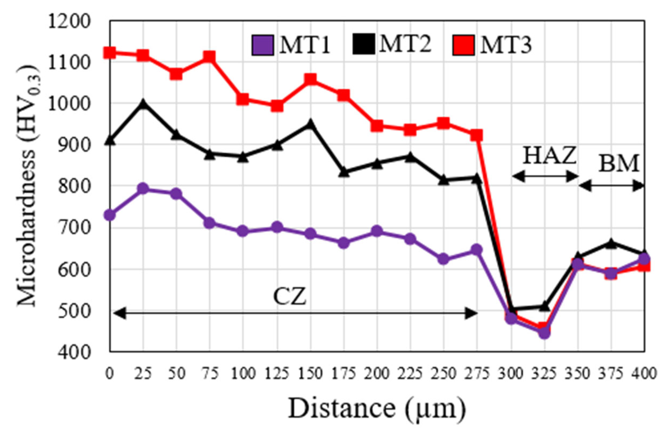
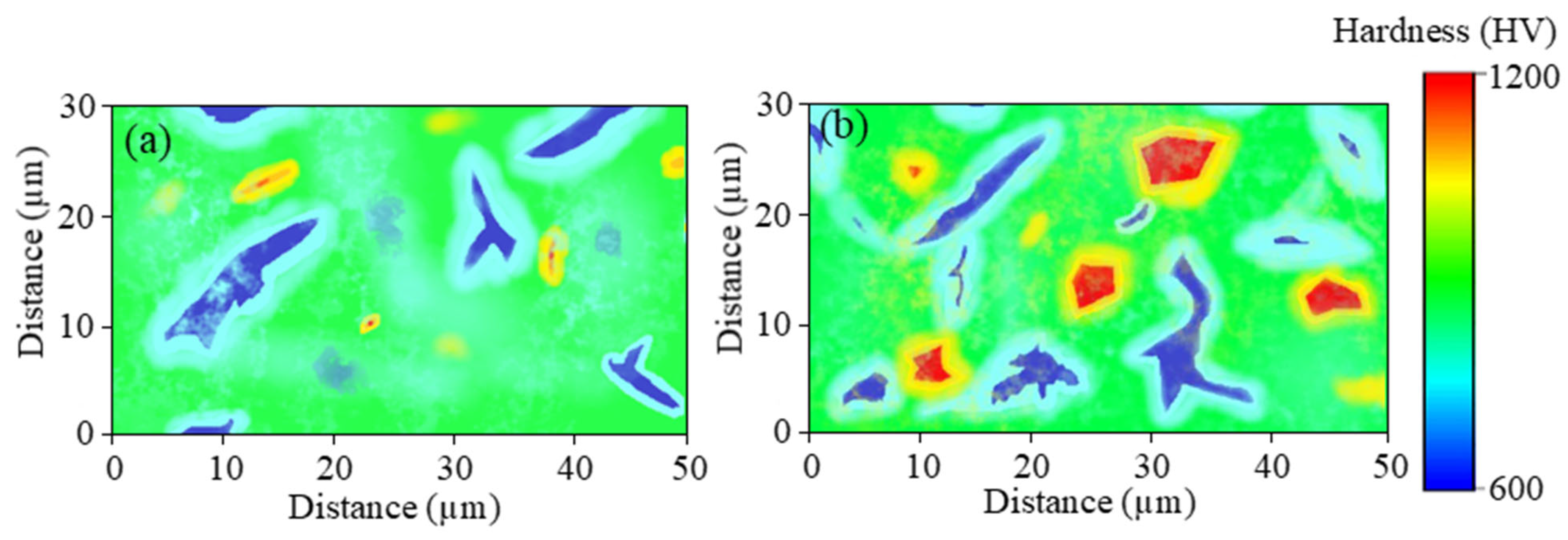
3.3. Hardness Analysis

The hardness measurement behavior of the three types of coatings at different intervals is presented in Figure 9. As can be seen, the lowest and highest hardness values belonged to the sample MT1 with an average hardness of 692 HV0.3, and MT3 with an average hardness of 992 HV0.3, respectively. hBN does not cause high hardness due to its inherent layered structure. On the other hand, with the presence of columnar dendrites, loose morphology, and the low volume fraction of equiaxed crystals, the hardness value in sample MT1 is lower than the other two samples. The hardness results of the MT2 sample (907 HV0.3) show an impressive 24% increase in hardness compared to the MT1 sample. Such a result was not far from expected. Because cBN is the hardest material after diamond, its hardness is several times that of hBN, as reported in the literature [35]. The high hardness of cBN induces the driving force of inhomogeneous nucleation in the molten pool, which reduces the size of dendrites and grown crystals. However, the hardness of the MT3 sample is about 10% more than the MT2 sample. This increase in hardness due to the addition of hBN is attributed to the decomposition of hBN during laser cladding, resulting in the formation of Cr-rich borides and creating more inhomogeneous nucleation centers. Therefore, adding cBN to the coating has a significant effect on increasing the hardness compared to hBN.
Furthermore, as mentioned in the microstructural analysis section, the simultaneous addition of hBN and cBN resulted in the formation of equiaxed grains in the top and bottom regions of the coating (see Figure 7). This microstructural evolution resulted in higher hardness, as the refined equiaxed grains act as barriers to dislocation motion, further strengthening the coating. The hardness contour diagram in Figure 10 confirms this. As it is clear from the hardness contour results and expected, cBN-rich areas have the highest concentration of hardness compared to other parts of the coating. Moreover, as shown in Figure 9, the heat-affected zone (HAZ), with a hardness of 477 HV0.3, has lower hardness compared to the base metal (BM), which has a hardness of 613 HV0.3. This is attributed to the heat input from the laser and subsequent grain growth. According to the Hall-Petch relationship [36], an increase in grain size leads to a decrease in hardness. Wei et al. [33] also reported a reduction in hardness in the HAZ of GTD-111 superalloy coating with ZrB2/ZrC+ Ni60A/WC composite due to grain growth in this region.

3.4. Wear Resistance Analysis

Figure 11 shows the experimental wear results, including COF and average COF. As can be seen, the average COF of MT1, MT2, and MT3 samples was equal to 0.49, 0.53, and 0.41, respectively. According to Figure 11, the MT2 sample shows the highest COF and the highest fluctuation. This is attributed to the presence of cBN hard particles. An abrasive ball, which is made of Si3N4 hard material, is also considered a hard material. Friction between cBN and Si3N4 leads to grinding friction and, thus, wear and tear on one side. Under such conditions, the roughness of the contact surface increases and, as a result, increases the COF and the resulting fluctuation. However, it can be seen that the resulting COF fluctuations decrease after about 200 m. Of course, this decreasing trend is also observed in two other samples. The reason for this is the transformation of the point contact between the abrasive ball and the sample’s surface with time from a point to a plane. Shi et al. [37] reported that cBN particles strongly decrease the tendency to increase surface roughness and COF fluctuations in Ni/c-BN composite during wear test. As reported by Sahoo et al. [38], the TiB2/ZE41-PA composite demonstrated a significant reduction in wear-induced deformation and subsurface instability compared to ZE41, making it the most effective material for high-temperature wear resistance.
As expected, the MT1 and MT3 samples showed lower COF and fluctuation due to the presence of hBN than the MT2 sample, which only contained cBN. In the literature, the reason for the reduction of COF with the increase of hBN is attributed to its unique crystalline properties [28]. The weak van der Waals bonding force between the layers of the hBN hexagonal structure and the strong bonding force between the B-N atoms increase the tendency of the layers to slip during the wear test. In addition, it has been reported that hBN is easily adsorbed on metal surfaces and reduces the COF by creating a slippery layer [39]. However, the wear test results show that the average COF of the MT3 sample has decreased by about 29% compared to the MT1 sample. This is attributed to the remarkable difference in elastic modulus between cBN (~800–900 GPa) and hBN (~30–60 GPa), which helps to promote the lubricant release of hBN [40].
Figure 12 shows the results of wear rate and wear volume loss. As can be seen, according to the COF results, the MT3 sample has the lowest wear rate (0.22 × 10⁻⁶ mm3/N·m) and wear volume loss (0.032 × 105 µm3). As mentioned, the combination of hBN and ultra-hard cBN lubricant particles and the significant difference in the elastic modulus of these two particles is essential in the resistance to elastic and plastic deformation against the Si3N4 wear ball during the wear test. The results of two-dimensional and three-dimensional wear topography in Figure 13 also show that the MT3 coating with the lowest surface roughness and wear depth of 7.5 µm has the highest wear resistance. However, despite the lubricating property of hBN compared to cBN, the wear rate and wear volume loss results show that the MT2 sample had a 74% lower wear rate than MT1. This is attributed to the hard cBN particles resisting the hard Si3N4 wear ball and possibly the Si3N4 being worn. It is stated in the literature that hard cBN particles are more resistant to forces and stresses caused by sliding or rubbing on other surfaces than hBN. The three-dimensional topography of the surface of the MT2 sample with higher roughness but lower wear depth shows the hardness of cBN particles and its hard frictional interaction with the Si3N4 wear ball (Figure 13). Meanwhile, the MT1 sample is confirmed to have a smooth wear surface but a greater wear depth.

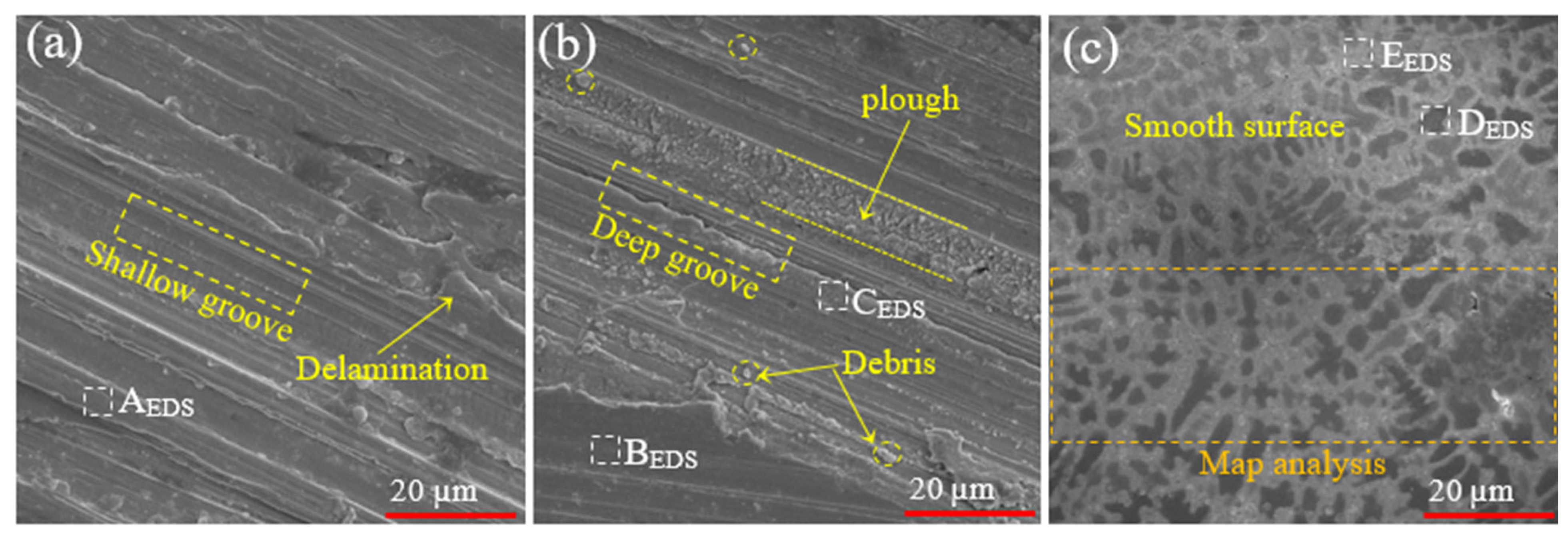
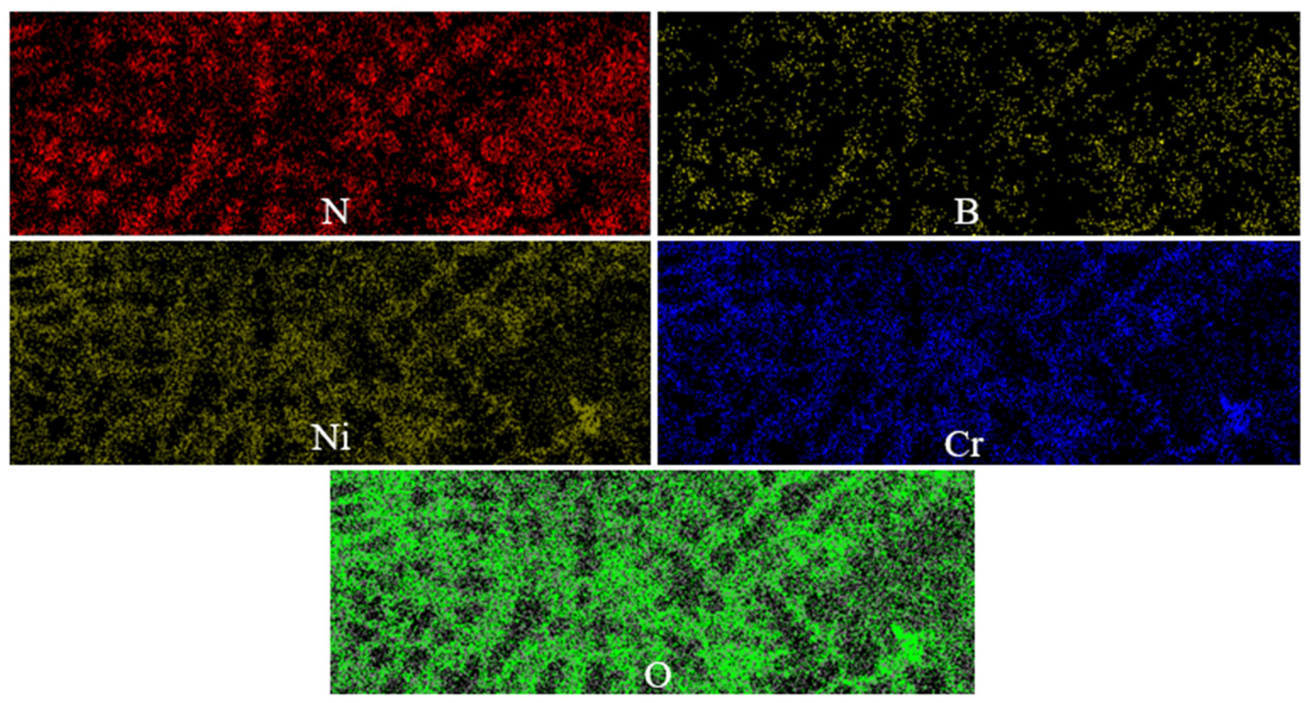
3.5. Worn Surface Analysis

Figure 14 shows the surface topography of different samples in worn surface conditions. The roughness and grooves of the wear surfaces are by the three-dimensional topography in Figure 13. The MT2 sample has the most plow, furrow, and wear debris, and the MT1 sample has the least. As shown in Figure 14a, flaking occurred on the surface of specimen MT1 after the wear test. Although the MT1 sample has the highest wear rate, the least signs of grooves, plows, and wear debris are observed. This is attributed to the lubrication property and hexagonal structure of hBN [39,40]. It is true that the hBN layers, like graphite, act like a slider against the abrasion force, but the higher force of the abrasion ball breaks the van der Waals bond between the layers and causes peeling and reaching a new layer. Therefore, when a new layer is reached, the worn surface is expected to be almost smooth. However, some signs of wear, such as wear dust, are observed on the surface of the MT1 sample. By analyzing area A (Table 5), it was observed that there is a large amount of oxygen on the sample’s surface. This issue indicates the occurrence of oxidative wear in MT1 coating. Under such conditions, the adhesive wear mechanism causes delamination with different thicknesses due to differences in grinding pairs and other coating adhesion sizes.
The worn surface images of the MT2 sample show that despite the lower wear rate, more wear debris and plows are observed in the wear. The cubic and hard structure of cBN, in contrast with the Si3N4 abrasive ball, is susceptible to plowing and the generation of wear debris. However, the integrated and non-layered structure of cBN does not allow further wear and penetration into the next layer. This has caused the production of more wear debris, plow, and furrow, but with the lowest depth compared to the MT1 sample. Due to the presence of abrasive particles and debris created on the surface, the wear mechanism of the MT2 sample is of the abrasive type. The EDS analysis of points B and C shows that point B contains more oxygen than C, which indicates oxidation during the wear test due to the friction between the two materials. Less oxygen in region C, near the groove edges, confirms that the abrasive particles remove the oxide layer as soon as it is formed and prevent the formation of a stable oxide layer.
As seen in Figure 14c, the MT3 coating did not have a layered surface (like the MT1 coating) or a groove (like the MT2 coating). Rather, the coating surface was almost smooth and in two colors after the wear test. The results of the EDS analysis in Table 5 showed that the dark areas (point D) are rich in oxygen, and it can be said that they are the areas that underwent oxidation during the wear test. This is while the bright regions (point E) are poor in oxygen, and oxidation has not occurred. However, some element N was observed at point E. To investigate this issue, a Map analysis (Figure 15) was performed on the dark and bright spots of the MT3 coating surface, which showed that the bright areas are rich in hBN particles, which act as a lubricating film to prevent the formation of an oxidation layer due to its lubricating properties during friction. It works. The combination of hNB lubricant particles and cBN hard particles in the MT3 coating reduces the wear rate and COF, as well as shallow grooves and low plowing.
In addition to the positive role of hBN and cBN ceramic particles in increasing the wear resistance of MT3 coating, the expansion of equiaxed grains, which are often rich in Cr and Ni, is another important factor in increasing the wear resistance of MT3 sample (see Figure 7). The volume fraction of equiaxed grains measured by Image J software was 35%, 56%, and 79% in samples MT1, MT2, and MT3, respectively. These equiaxed grains increase wear resistance by creating a more uniform and stable surface through better stress distribution and prevention of stress concentration, as well as by reducing plowing and the formation of wear debris [41]. Under such conditions, internal friction is reduced, and less energy is consumed for surface deformation, resulting in a reduced wear rate. In addition, coatings with equiaxed grains have better adhesion to the substrate and are more resistant to delamination, which increases their durability and lifespan. Huang et al. [42] reported that fine equiaxed grains formed in the friction stir processed AlFeCrCuNi-type high-entropy alloy accelerate the formation of an oxide layer on the coating surface, thereby delaying coating plowing and reducing COF.
To accurately check the wear mechanism of the resulting coatings, the schematic of the occurrence of wear of all three coatings is presented in Figure 16. As can be seen, Figure 16a shows the porous coating with low bonding force between the coatings, low hardness, low density, and finally low resistance to deformation of the coating. As the coating is subjected to wear and friction by the wear ball, the hBN lubricant particles were removed one layer after another after forming a lubricant layer. The low COF of the MT1 coating (see Figure 11) was due to the low shear force caused by the sliding slippage of the layers and the weak van der Waals force between the layers. Jiang et al. [43] reported that hBN-based coatings exhibit a similar layered wear mechanism to that observed in MT1 coating, where the lubricating layers gradually peel off. The MT2 coating (Figure 16b) had cBN hard particles to support the wear-resistant behavior of the coating. In the process of friction with the wear pair, with time, the friction between the point of the wear pair and the main point turns into point-to-point friction, and the wear pair slips on the hard particle. The point-to-point contact during continued wear causes hard impacts between the wear pair and the hard cBN particles, resulting in its debris falling around the original cBN. These debris rubs, which are guided by the grinding pair, cause the formation of abrasive particles and grooves in the continuation of the wear process. Therefore, cBN-reinforced coatings (MT2 coating) have been shown to form hard debris that contributes to abrasive wear, as observed in the study by Sun et al. [44]. The MT3 coating benefits from both the hBN softener in the MT1 coating and the hard cBN particles in the MT2 coating to create a wear-resistant coating. cBN particles (harder material) reduce the material removal rate by resisting material deformation. However, with the passage of time and the change of the shape of the coating, the cBN particles act as a grinding platform and cause the formation of a lubricant layer (hBN particles) on the surface of the coating. Under such conditions, the lubricant layer removes the direct contact of the wear pair with the coating. On the other hand, the cBN hard particles that support this lubricant layer increase the wear resistance. However, the findings of this study reveal a unique synergistic effect in MT3, where the interaction between hBN and cBN leads to self-lubricating and wear-resistant behavior, which has not been explicitly discussed in previous works.

4. Conclusions

In this study, the effect of hBN and cBN was investigated individually and simultaneously on the wear behavior of NiCr processed by laser cladding on GTD-111 superalloy, and the following results were obtained:
  • Regardless of the role of wear improver, NiCr-2%hBN-12%cBN coating improves compaction, removes defects, and improves microstructure.
  • The NiCr-2%hBN-12%cBN coating showed a 43% and 10% increase in hardness compared to the coatings reinforced with hBN and cBN, respectively. This was because of the high hardness of cBN and the simultaneous creation of inhomogeneous nucleation sites by hBN and cBN.
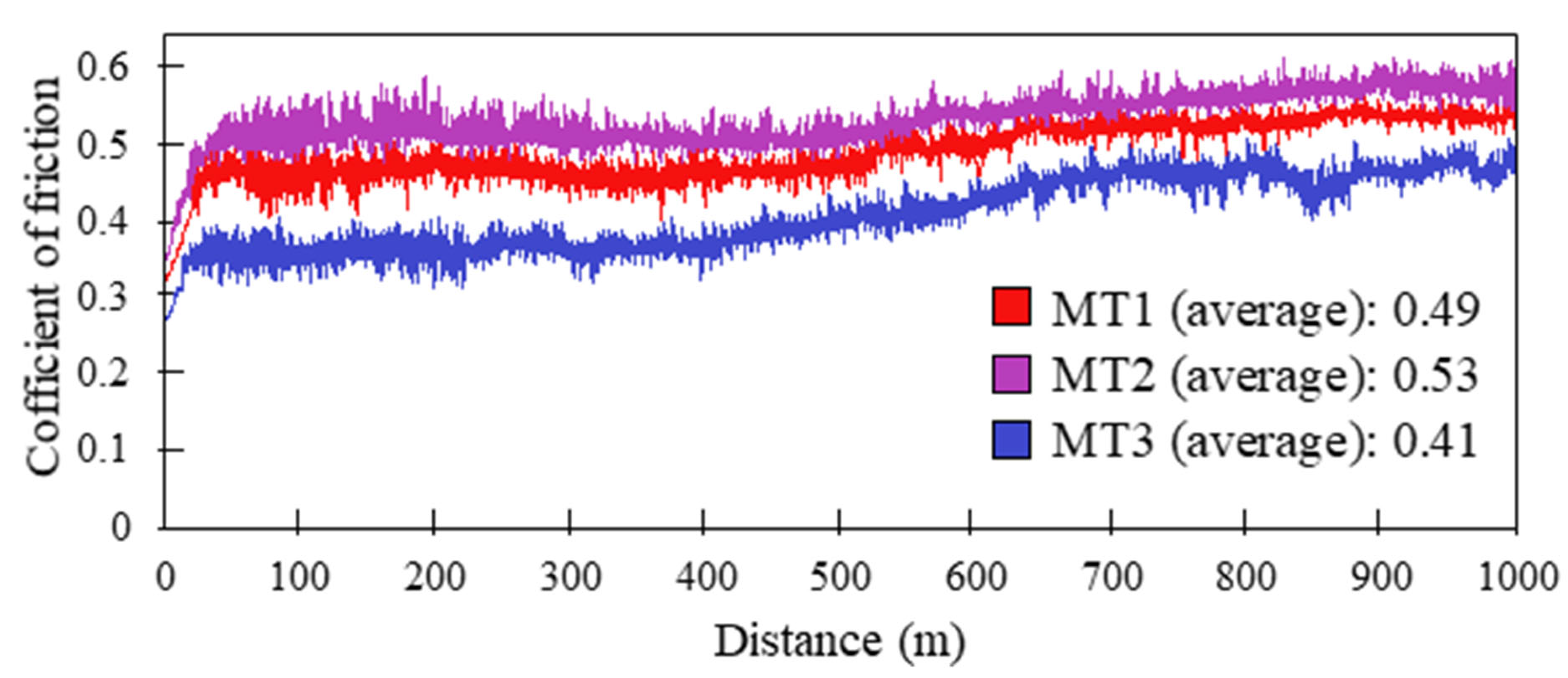
  • The simultaneous presence of hBN and cBN in the NiCr-2%hBN-12%cBN coating caused an increase in the driving force of nucleation and expansion of the equiaxed grain area. This, along with the hardening role of cBN and self-lubricating hBN, reduced the COF compared to the other two coatings.
  • The NiCr-2%hBN coating had a higher wear rate (0.54 × 10⁻⁶ mm3/N·m) but with a lower fluctuation due to the B-N layer bond than the NiCr-12%cBN coating, which had a lower wear rate (0.31 × 10⁻⁶ mm3/N·m) but with a higher fluctuation. Combining hBN and cBN in the NiCr-2%hBN-12%cBN coating made use of the effective role of each of the above particles to achieve high wear resistance with reduced wear rate (0.22 × 10⁻⁶ mm3/N·m) and fluctuation.
  • The wear mechanisms for hBN, cBN, and hBN-cBN reinforced coatings were adhesive wear, abrasive wear, and oxidative wear, respectively. The simultaneous presence of hBN-cBN does not have plow and debris like cBN coating. HBN causes self-lubrication, and cBN prevents Si3N4 abrasive ball from penetrating the next layers.

Author Contributions

Conceptualization, data curation, formal analysis, investigation, M.T.; methodology, project administration, supervision, validation, K.S.; visualization, writing—original draft, writing—review and editing, M.T. and K.S. All authors have read and agreed to the published version of the manuscript.

Funding

This research received no external funding.

Institutional Review Board Statement

Not applicable.

Informed Consent Statement

Not applicable.

Data Availability Statement

Data are contained within the article.

Conflicts of Interest

The authors declare no conflicts of interest.

References

  1. Gudivada, G.; Pandey, A.K. Recent developments in nickel-based superalloys for gas turbine applications. J. Alloys Compd. 2023, 963, 171128. [Google Scholar]
  2. Chowdhury, T.S.; Mohsin, F.T.; Tonni, M.M.; Mita, M.N.H.; Ehsan, M.M. A critical review on gas turbine cooling performance and failure analysis of turbine blades. Int. J. Thermofluids 2023, 18, 100329. [Google Scholar] [CrossRef]
  3. Zheng, Z.; Sun, H.; Xue, W.; Duan, D.; Chen, G.; Zhou, X.; Sun, J. Preparation of protective coatings for the leading edge of wind turbine blades and investigation of their water droplet erosion behavior. Wear 2024, 558, 205568. [Google Scholar] [CrossRef]
  4. Asadi, J.; Sajjadi, S.A.; Omidvar, H. New insights into microstructural changes during transient liquid phase bonding of GTD-111 superalloy. Trans. Nonferrous Met. Soc. China 2021, 31, 2703–2715. [Google Scholar]
  5. Fang, Z.; Zeng, G.; Li, Y.; Wang, Z.; Xiao, L.; Jia, S.; Qin, C. Laser Power Modulation of Fiber Coated with Multilayer-Graphene Based on Lithium Intercalation Method. Photonics 2025, 12, 169. [Google Scholar] [CrossRef]
  6. Basingala, P.K.; Neigapula, V.S.N. Thermal stability and anti-ablation performance of plasma spray coated-YSZ on Al2TiO5 modified novel ablative carbon-phenolic composites. Phys. Scr. 2024, 99, 115027. [Google Scholar]
  7. Abro, I.A.; Chandio, A.D. Analysis and evolution on diffusional stability of nickel aluminide bond coat via nickel electro-plating. Eur. Phys. J. Plus 2023, 138, 229. [Google Scholar]
  8. Taheri, M.; Salemi Golezani, A.; Shirvani, K. Effect of Aluminide coating on rapture behavior of Ni-based superalloy GTD-111 in high temperature. Adv. Mater. Res. 2012, 457, 330–333. [Google Scholar]
  9. Zhao, S.; Taheri, M.; Shirvani, K.; Naserlouei, M.; Beirami, K.; Paidar, M.; Sai, W. Microstructure of NbMoTaTiNi refractory high-entropy alloy coating fabricated by ultrasonic field-assisted laser cladding process. Coatings 2023, 13, 995. [Google Scholar] [CrossRef]
  10. Sudas, D.P.; Popov, S.M.; Kuznetsov, P.I. In Situ Preparation of Thin-Film Q-Switches Based on Vanadium Dioxide for Pulsed Fiber Lasers. Photonics 2025, 12, 133. [Google Scholar] [CrossRef]
  11. Soltanipour, A.; Sohi, M.H.; Shoja-Razavi, R.; Barekat, M.; Erfanmanes, M. Effect of processing parameters on the microstructure of laser-clad Stellite 6 on the X19CrMoNbVN11-1 stainless-steel substrate. Heliyon 2024, 10, e30176. [Google Scholar] [PubMed]
  12. He, Y.; Taheri, M.; Zou, Y.; Lashkari, A.; Shirvani, K.; Beirami, K.; Moghaddam, A.P. Investigating the microstructure and tribological properties of ZrB2 and ZrB2/TiB2 coatings applied by ultrasonic field-assisted laser cladding. Mater. Lett. 2024, 365, 136449. [Google Scholar]
  13. Wu, Z.; Taheri, M.; Shirvani, K.; Raji, E.; Torkamany, M.J.; Jelodar, R.T. Development of NiCrFeCoBX eutectic high entropy alloy coating by laser cladding: Investigation of microstructural, solidification, corrosion, and wear properties. Mater. Chem. Phys. 2024, 320, 129428. [Google Scholar]
  14. Alizadeh-Sh, M.; Marashi, S.P.H.; Ranjbarnodeh, E.; Shoja-Razavi, R.; Oliveira, J.P. Prediction of solidification cracking by an empirical-statistical analysis for laser cladding of Inconel 718 powder on a non-weldable substrate. Opt. Laser Technol. 2020, 128, 106244. [Google Scholar]
  15. Wen, H.M.; Pang, M.; Hu, Y.J. Study on fabrication of multi-phase reinforcement coatings on Ti6Al4V by laser cladding for enhanced tribological performance. Mater. Today Commun. 2024, 41, 110566. [Google Scholar]
  16. Zhikai, Z.; Wenqing, S.; Yang, Z.; Tianwen, J.; Kaiyue, L. Microstructure and properties analysis of Ni60-based/WC composite coatings prepared by laser cladding. Heliyon 2024, 10, e24494. [Google Scholar]
  17. Sahoo, S.K.; Panigrahi, S.K. Synergetic effect of in-situ TiB2 reinforcement and nano precipitation on wear behavior of ZE41 magnesium matrix composite. Wear 2025, 560, 205609. [Google Scholar]
  18. Liu, Y.; Ding, Y.; Yang, L.; Sun, R.; Zhang, T.; Yang, X. Research and progress of laser cladding on engineering alloys: A review. J. Manuf. Process. 2021, 66, 341–363. [Google Scholar]
  19. Zhu, L.; Xue, P.; Lan, Q.; Meng, G.; Ren, Y.; Yang, Z.; Xu, P.; Liu, Z. Recent research and development status of laser cladding: A review. Opt. Laser Technol. 2021, 138, 106915. [Google Scholar]
  20. Horlu, M.; Macit, C.K.; Aksakal, B.; Tanyeri, B. Tribological and Structural Effects of Titanium Carbide and Hexagonal Boron Nitride Reinforcement on Aluminum Matrix Hybrid Composites. Arab. J. Sci. Eng. 2024, 49, 14875–14893. [Google Scholar]
  21. Zhao, X.; Yu, T.; Zhao, Y.; Zhang, Y.; Yang, L.; Jiang, S.; Wang, W. Laser cladding Ti coated CBN/CuSnTi alloy on steel for grinding tools of ocean ship. J. Coast. Res. 2018, 83, 571–578. [Google Scholar] [CrossRef]
  22. Almehmadi, S.J.; Alruqi, A.B.; Alsalmah, H.A.; Farea, M.O.; Masmali, N.A.; Al-Sulami, A.I.; Al-Ejji, M.; Rajeh, A. Improving the optical, photoluminescence, and electrical properties of PEO/NaAlg-WO3 nanocomposites for optoelectronic and nanodielectric applications. J. Mater. Res. Technol. 2023, 26, 2310–2318. [Google Scholar] [CrossRef]
  23. Zhao, S.G.; Yao, X.M.; Li, R. Microhardness Analysis of Laser Cladding CBN coating on the Surface of Titanium Alloy. Appl. Mech. Mater. 2014, 551, 3–6. [Google Scholar] [CrossRef]
  24. Niksefat, V.; Mahboubi, F. Tribological performance of plasma-nitrided self-lubricant electroless Ni-B-graphite composite coatings. Tribol. Int. 2024, 198, 109905. [Google Scholar] [CrossRef]
  25. Wen, X.; Qu, R.; Yuwen, F.; Qiao, Y.; Wang, T.; Yao, R.; Lu, J. Genesis and robust tribological property of friction-induced Cu-graphene self-lubricating composite under electrical contact. Tribol. Lett. 2023, 71, 82. [Google Scholar] [CrossRef]
  26. Li, Z.; Song, K.; Bai, Y.; Cong, D.; Zhang, M.; Peng, D.; Wang, X.; Ding, X.; Liao, M.; Zhou, F.; et al. Study on the Wear and Corrosion Resistance of CoCrFeNiTi0. 8-xcBN Laser Cladding Coatings. J. Therm. Spray Technol. 2024, 33, 1440–1454. [Google Scholar] [CrossRef]
  27. Kuang, W.; Zhao, B.; Yang, C.; Ding, W. Effects of h-BN particles on the microstructure and tribological property of self-lubrication CBN abrasive composites. Ceram. Int. 2020, 46, 2457–2464. [Google Scholar] [CrossRef]
  28. Tan, Q.; Liu, K.; Li, J.; Geng, S.; Sun, L.; Skuratov, V. A review on cracking mechanism and suppression strategy of nickel-based superalloys during laser cladding. J. Alloys Compd. 2024, 1001, 175164. [Google Scholar] [CrossRef]
  29. Sun, D.; Zhu, L.; Cai, Y.; Yan, Y.; Ge, F.; Shan, M.; Tian, Y.; Han, J.; Jiang, Z. Tribology comparison of laser-cladded CrMnFeCoNi coatings reinforced by three types of ceramic (TiC/NbC/B4C). Surf. Coat. Technol. 2022, 450, 129013. [Google Scholar] [CrossRef]
  30. Ramkumar, K.R.; Balasundaram, A.; Bisht, A.; Kamaraj, M.; Bakshi, S.R. Microstructure and wear properties of cold-sprayed NiCr-Tribaloy (T800) coating on Nimonic 80A. Surf. Coat. Technol. 2024, 494, 131374. [Google Scholar] [CrossRef]
  31. Li, Q.; Cui, J.; Yang, Y.; Li, J.; Zhao, Y.; Yu, C.; Wang, Q.; Zhang, P. Enhanced surface wettability modification of Al2O3 for laser cladding ceramic-metal composite coatings. Mater. Today Commun. 2024, 40, 109746. [Google Scholar] [CrossRef]
  32. Taheri, M.; Kashani-Bozorg, S.F.; Alizadeh, A.; Beni, M.H.; Jam, J.E.; Khorram, A. Analysis of liquation and solidification cracks in the electron beam welding of GTD-111 nickel-base superalloy joint. Mater. Res. Express 2021, 8, 076507. [Google Scholar] [CrossRef]
  33. Wei, Z.; Najafi, A.; Taheri, M.; Soleymani, F.; Didehvar, N.; Khalaj, G. The effect of an ultrasonic field on the microstructure and tribological behavior of ZrB2/ZrC+ Ni60A/WC composite coating applied by laser cladding. Coatings 2023, 13, 1928. [Google Scholar] [CrossRef]
  34. Zhang, Y.; Hou, W.; Yu, J.; Chen, C.; Zhou, L. The role of carbon in wear resistance of CoCrFeNiTi0.5 high-entropy alloy layer. J. Mater. Eng. Perform. 2024, 34, 1417–1429. [Google Scholar] [CrossRef]
  35. Xiao, G.; Zhao, B.; Ding, W. Mechanical and tribological properties of porous metallic CBN composites reinforced by graphene nanoparticles. Int. J. Adv. Manuf. Technol. 2021, 114, 397–405. [Google Scholar] [CrossRef]
  36. Sun, C.; Kong, D. Microstructure and tribological behaviors of laser cladded CuAlMnTi–xTiC composite coatings at elevated temperature. Mater. Today Commun. 2024, 39, 109065. [Google Scholar]
  37. Shi, K.; Du, X.; Sun, Y.; Wang, Z. Microstructure and Properties of Nickel-Clad Cubic Boron Nitride-Reinforced Ni-Based Composite Coating Laser Cladding on Martensitic Stainless Steel Substrates. J. Therm. Spray Technol. 2023, 32, 2133–2143. [Google Scholar] [CrossRef]
  38. Sahoo, S.K.; Ramesh, M.R.; Panigrahi, S.K. Establishing high temperature tribological performance and wear mechanism map of engineered in-situ TiB2 reinforced Mg-RE metal matrix composites. Tribol. Int. 2025, 201, 110189. [Google Scholar] [CrossRef]
  39. Liu, Y.; Liu, L.; Shi, P.; Wang, Y.; Qian, L.; Chen, L. Improved wear resistance of CBN tool enabled by hBN as a water-based lubricant additive through suppressing tribochemical reactions. Ceram. Int. 2023, 49, 17953–17960. [Google Scholar] [CrossRef]
  40. Chen, S.N.; Fan, H.; Su, Y.; Li, J.; Song, J.; Hu, L.; Zhang, Y. Bioinspired PcBN/hBN fibrous monolithic ceramic: High-temperature crack resistance responses and self-lubricating performances. J. Adv. Ceram. 2022, 11, 1391–1403. [Google Scholar] [CrossRef]
  41. Han, J.; Tang, S.; Guan, J.; Mao, Y.; Zhu, K.; Li, Y.; Li, P. Microstructure and wear property of (TiN + NbC) double ceramic phase-reinforced in FeCrNiCoAl high-entropy alloy coating fabricated by laser cladding. Ceram. Int. 2024, 50, 49066–49084. [Google Scholar] [CrossRef]
  42. Huang, G.Q.; Sun, T.; Meng, F.Q.; Jiang, X.W.; Chou, T.H.; Ju, J.; Gan, J.; Yang, T.; Li, M.S.; Shen, Z.K.; et al. Microstructural evolution and wear behavior of friction stir processed L12 strengthened AlFeCrCuNi-type high-entropy alloy. Mater. Charact. 2024, 216, 114250. [Google Scholar] [CrossRef]
  43. Jiang, G.Y.; Xu, Z.Y. Microstructure and tribological performance of laser cladding co-based laser coatings with h-BN and Fe addition. Mater. Today Commun. 2024, 39, 108896. [Google Scholar] [CrossRef]
  44. Sun, Z.; Zhao, J.; Yu, T.; Meng, F.; Sun, J.; Wang, Y. Effect of laser power on morphology, microstructure and mechanical properties of CBN abrasive block prepared by two-step laser cladding. Ceram. Int. 2024, 50, 29841–29849. [Google Scholar] [CrossRef]
Figure 1. Particle size distribution of the powder components, (a) Ni, (b) hBN, (c) Cr, and (d) cBN.
Photonics 12 00265 g001
Figure 2. XRD pattern of Ni, Cr, hBN, and cBN mixed powders before laser cladding.
Photonics 12 00265 g002
Figure 3. Schematic illustration of the laser cladding process.
Photonics 12 00265 g003
Figure 4. (a) Schematic illustration of the microhardness test and (b) pin-on-disc wear test.
Photonics 12 00265 g004
Figure 5. Phase analysis diagram of MT1, MT2, and MT3 coatings: (a) X-ray diffraction pattern and (b) Raman spectrogram.
Photonics 12 00265 g005
Figure 6. SEM image showing the profile of coated samples: (a) MT1, (b) MT2, and (c) MT3.
Photonics 12 00265 g006
Figure 7. Cross-sectional SEM images of the coated area of samples (a) MT1, (b) MT2, and (c) MT3. (a) shows the overall coating profile, while (a1,a2) are magnified views of the marked areas in (a). Similarly, (b1,b2) correspond to the overall coating profile and magnified views of MT2, respectively, and (c1,c2) show the overall coating profile and magnified views of MT3.
Photonics 12 00265 g007
Figure 8. Map analysis of particle distribution to illustrate the dispersion and decomposition behavior: (a) hBN in sample MT1 and (b) cBN in sample MT2.
Photonics 12 00265 g008
Figure 9. Hardness variations in the clad zone of different samples.
Photonics 12 00265 g009
Figure 10. Contour plots of hardness distribution: (a) MT1, (b) MT2.
Photonics 12 00265 g010
Figure 11. Diagram of the coefficient of friction of samples MT1, MT2, and MT3 based on the distance traveled.
Photonics 12 00265 g011
Figure 12. Wear rate and wear volume loss results of wear test for MT1, MT2, and MT3 samples.
Photonics 12 00265 g012
Figure 13. 3D profiles of worn surface, (a) MT1, (b) MT2, and (c) MT3, (d) wear scar in different coatings.
Photonics 12 00265 g013
Figure 14. Worn surface after the wear test for (a) MT1, (b) MT2, and (c) MT3.
Photonics 12 00265 g014
Figure 15. Map analysis of the area marked in Figure 14c for sample MT3.
Photonics 12 00265 g015
Figure 16. Schematic illustration of the wear mechanism for (a) MT1, (b) MT2, and (c) MT3.
Photonics 12 00265 g016
Table 1. Chemical composition of GTD-111 superalloy (substrate) in weight percentage (wt.%).
AlTiCrCoTaWMoCFeBZrNi
3.14.814.28.41.831.60.10.080.0150.04Bal
Table 2. Composition of NiCr/hBN-cBN coating with varying amounts of added hBN and cBN (wt.%).
Metal (Matrix)Ceramic (Reinforcement)
SpecimenNiCrhBNcBN
MT180202-
MT28020-12
MT38020212
Table 3. Parameters used for NiCr/hBN-cBN composite deposition on GTD-111 superalloy.
Scan Speed (mm/s)Pulse Frequency (Hz)Pulse Duration (ms)Spot Diameter (mm)Protective Gas (Ar) (L/min)Carrier Gas (Ar) (L/min)
8 20 72 20 15
Table 4. EDS analysis results of the marked areas in Figure 7 (wt.%).
SpecimenZoneNiCrBNCo
MT1A52.747.3---
B53.644.1--2.3
MT2C66.229.2--4.6
D7.576.610.35.6-
MT3E10.932.413.77.8-
F65.129.4--5.5
Table 5. EDS analysis results of the marked areas in Figure 14 (wt.%).
SpecimenZoneNiCrBNO
MT1A19.513.8--66.7
MT2B13.417.4--69.2
C19.634.6--45.8
MT3D13.115.6 71.3
E42.632.8-2.721.6
Disclaimer/Publisher’s Note: The statements, opinions and data contained in all publications are solely those of the individual author(s) and contributor(s) and not of MDPI and/or the editor(s). MDPI and/or the editor(s) disclaim responsibility for any injury to people or property resulting from any ideas, methods, instructions or products referred to in the content.

