Article

Portable Filter-Free Lens-Free Incoherent Digital Holography System

Applied Electromagnetic Research Center, Radio Research Institute, National Institute of Information and Communications Technology (NICT), 4-2-1 Nukuikitamachi, Koganei, Tokyo 184-8795, Japan
Photonics 2025, 12(2), 167; https://doi.org/10.3390/photonics12020167
Submission received: 22 January 2025 / Revised: 13 February 2025 / Accepted: 14 February 2025 / Published: 19 February 2025
(This article belongs to the Special Issue Optical Imaging Innovations and Applications)

Abstract

:
A portable incoherent digital holography system without a polarization filter or a refractive lens was developed. Phase-shifted self-interference incoherent holograms of light diffracted from an object were generated without attenuation due to a polarization filter using two polarization-sensitive phase-only spatial light modulators (TPP-SLMs). The number of optical elements in filter-free lens-free incoherent digital holography was reduced to make the system compact and portable. Experiments were conducted using the developed digital holography system set on a tripod stand and objects illuminated by a light-emitting diode.

1. Introduction

Holography [1,2,3,4,5] is a technique to record three-dimensional (3D) information on an object on a photographic plate by exploiting the phase and interference of light and to reconstruct the 3D image of the object by applying the theory of diffraction of light. Quantitative phase information on light diffracted from an object is converted into intensity information by introducing both a reference wave and a two-wave interference and is recorded as an interference fringe image. The 3D information of an object is contained in the phase distribution of the interference fringe image. After processing the photographic plate, the 3D image of the object is optically reconstructed by illuminating the plate, which is termed a hologram, with a light wave whose wavefront is the same as that of the reference wave. Thus, the 3D information of an object is obtained from the two-dimensional intensity image(s). According to the sustainable developments and improvements of electronic devices, currently, an image sensor digitally records the interference fringe image(s), and a computer numerically reconstructs the 3D image. Such a holography technique is termed digital holography (DH) [6,7,8,9,10,11,12,13]. DH has enabled quantitative 3D measurements with nanometer-order accuracy in the depth direction [9,14], high-speed holographic 3D motion-picture imaging [15,16], and motion-picture and time-lapse observations of unstained living cells on quantitative phase images [9,14]. However, in general DH, spatially and temporally coherent illumination light, such as laser light, is required to obtain a digital hologram of an object, and it is difficult to acquire a digital hologram of self-luminous light irradiated from an object.
As seen in a soap bubble illuminated by sunlight and a Newton ring generated by white light, arbitrary light, including spatially and temporally incoherent light, interferes with itself. Such a phenomenon is termed self-interference. Studies on the holographic sensing of spatially incoherent light by exploiting self-interference, termed incoherent holography, have been conducted since the 1960s [17,18,19]. An incoherent hologram of an object was successfully acquired by incoherent holography with a mercury lamp [18]. Electronic devices are also actively adopted in incoherent holography, and this technique is termed incoherent digital holography (IDH) [13,20,21,22,23,24,25]. IDH is applied as a passive and monocular 3D image sensing technique with daily-use light, and it has enabled the holographic sensing of self-luminous light, such as fluorescence [26,27,28], Raman scattering [29], and sun light [30]. Full-color and hyperspectral 3D imaging of arbitrary light has been performed by using combinations of optical techniques, electronic devices, and digital signal processing [29,30,31,32,33,34]. Improvements in the specifications of electronic devices have also contributed to the downsizing of an IDH system, and new IDH systems adopting such electronic devices have been proposed. Fresnel incoherent correlation holography (FINCH) is one of the new IDH systems [21,22,23,24,27,35]. The initial FINCH system was basically composed of a phase-only spatial light modulator (SLM), an image sensor, and a computer [35]. Two Fresnel phase lenses with different focal lengths are simultaneously displayed on a liquid-crystal-on-silicon SLM (LCoS-SLM) on the basis of spatial multiplexing [21,27,35], and two object waves with different wavefront curvature radii are generated with the SLM. Compact IDH systems have been realized [27,35], and lensless incoherent 3D imaging has been performed using FINCH [36]. However, general phase-only SLMs can modulate only the phase of light polarized along a certain polarization direction. Therefore, light whose polarization direction is orthogonal to the modulation axis of the SLM is removed by a polarization filter, resulting in a decrease in the light-use efficiency. Therefore, IDH systems that adopt two polarization-sensitive phase-only SLMs (TPP-SLMs) have been developed to achieve filter-free IDH and increase the light-use efficiency [37,38,39]. However, the size of the system and the requirements of many refractive lenses have been problematic.
In this study, a compact, filter-free, and lens-free IDH system that adopts TPP-SLMs has been developed. The developed IDH system is manually portable andis set on a tripod stand. Experiments were conducted to demonstrate the filter-free lens-free incoherent 3D imaging capability of the system for transparent and reflective objects.

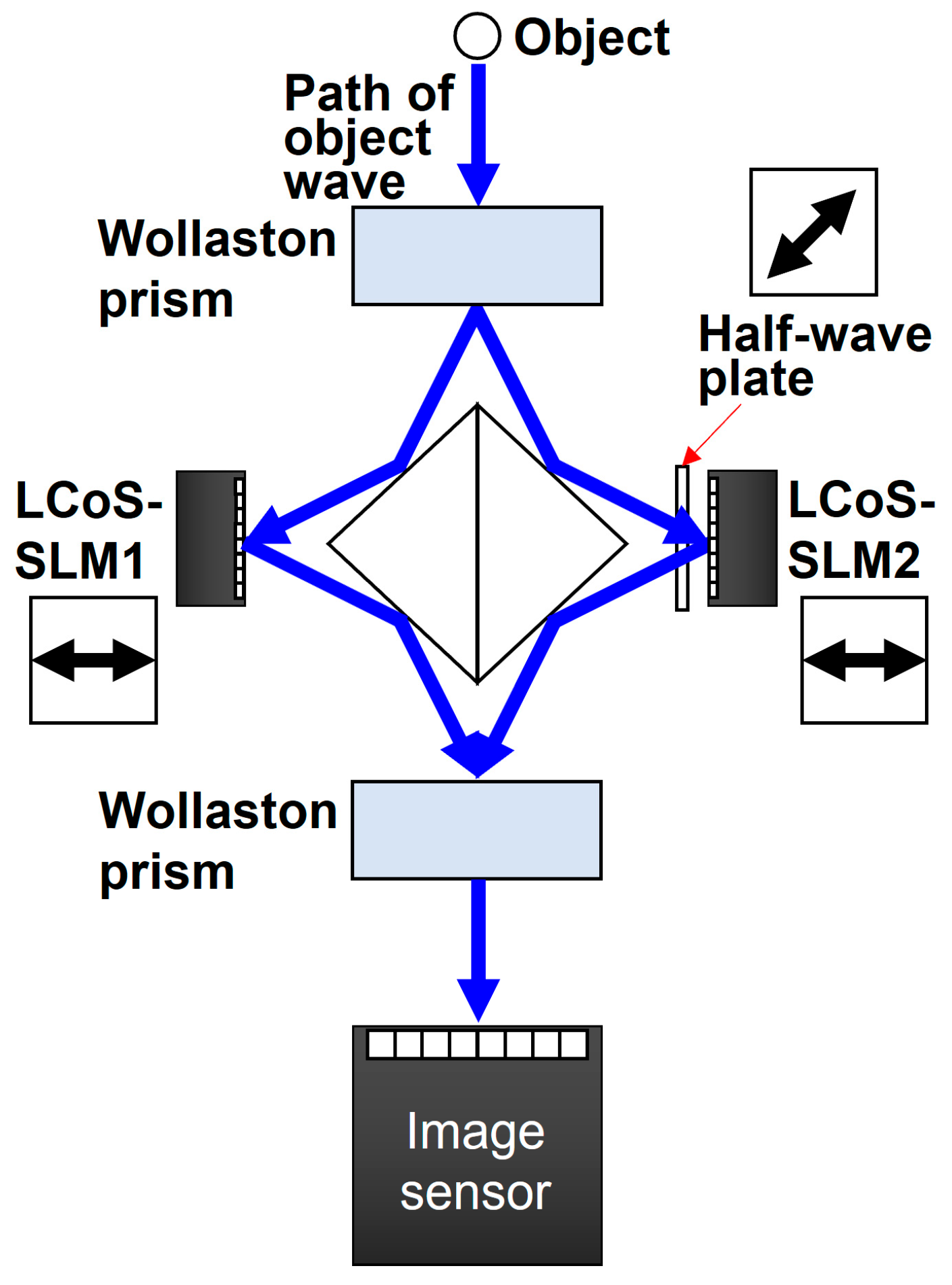
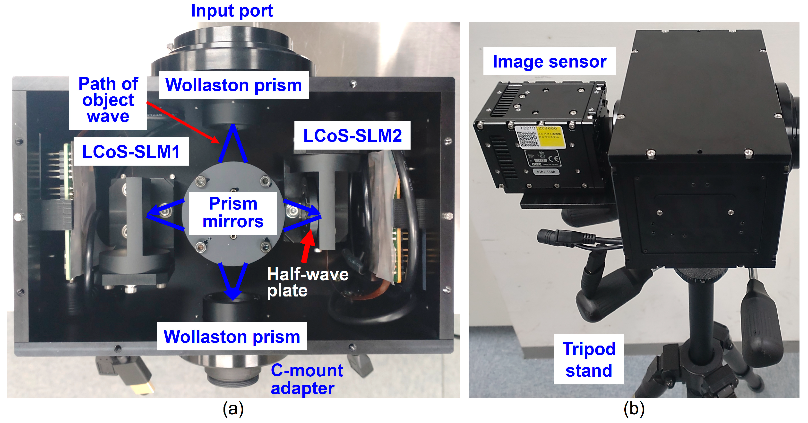
2. Developed Incoherent Digital Holography System

Figure 1 shows a schematic of the developed IDH system, which is composed of an optical setup and a laptop computer. The optical setup of the IDH system consists of two Wollaston prisms, two prism mirrors, TPP-SLMs, a half-wave plate, and an image sensor. A randomly polarized incoherent light wave diffracted from an object passes through a Wollaston prism, and then horizontally and vertically polarized object waves are separated by the prism. Respective prism mirrors reflect the respective object waves, which then obliquely illuminate the respective SLMs (SLM1 and SLM2). These SLMs display two Fresnel phase lenses with different focal lengths to generate two object waves with different wavefront curvature radii through FINCH with spatial multiplexing [21,27,35]. A half-wave plate is set in front of an LCoS-SLM2 to convert the vertically polarized object wave into the horizontally polarized one. This is because the modulation axis of the LCoS-SLM2 is along the horizontal direction, and it is favorable for incoherent holographic imaging to align the lengths along the horizontal and vertical directions of the TPP-SLMs. The vertically polarized object wave is first converted into a horizontally polarized one using the half-wave plate, modulated by the LCoS-SLM2, and then converted into a vertically polarized one again. The object waves are modulated by the corresponding LCoS-SLMs (SLM1 and SLM2), generating two horizontally and vertically polarized object waves. Thus, four polarized object waves are generated in total. These waves are combined by another Wollaston prism and illuminate the image sensor simultaneously. The same two object waves with different wavefront curvature radii can be generated in the horizontal and vertical directions by setting the same spatially multiplexed Fresnel phase lens on the respective SLMs. As a result, the image sensor records a self-interference incoherent digital hologram generated from two object waves with random polarization. A phase-shifted incoherent hologram is obtained by introducing the same phase shift on the respective SLMs, and multiple phase-shifted holograms are recorded with the image sensor by repeating the phase shifts and exposures. A recorded incoherent hologram H(x,y;q) is mathematically expressed as follows:
H ( x , y ; q ) = I ( x , y ; r o , θ ) d x o d y o d z o = H 0 t h ( x , y ) + U ( x , y ) e i θ + C . C . ,
I ( x , y ; r o , θ ) = C ( r o ) L r o z 1 Q 1 z 1 Q 1 f 1 + Q 1 f 2 e i θ Q 1 z 2 2 = C ( r o ) L f a r o z 1 ( f a + z 2 ) Q 1 f a + z 2 + C ( r o ) L f b r o z 1 ( f b + z 2 ) Q 1 f b + z 2 e i θ 2 = I 0 t h ( x , y ; r o ) + C ( r o ) L M r o f c Q 1 f c e i θ + c . c . ,
where U(x,y) is the object-wave information on the image sensor plane, generated from the incoherent sum of the sub-hologram I(x,y;ro,θ) of multiple object points ro = (xo,yo,zo); H0th(x,y) and I0th(x,y) are the 0th-order diffraction waves of H(x,y;θ) and I(x,y;ro,θ), respectively; i is an imaginary unit; C.C. and c.c. are the complex conjugates of U(x,y) and the second term of equation (2), respectively; C(ro), C’(ro), C″(ro), and C(ro) are coefficients; z1 is the depth difference between an object point and the SLMs; L = exp[i2π(xox + yoy)/λ] [36], where λ is the wavelength of light; Q(1/z) = exp[iπ(x2 + y2)/λz] [36]; * indicates a convolution; z2 is the depth difference between the SLMs and the image sensor; fa = f1z1/(f1z1); fb = f2z1/(f2z1); M = z2/z1 is the magnification of the IDH system; and fc = (fa + z2)(fb + z2)/(fafb) is the numerical focusing distance. Object-wave information is extracted by phase-shifting interferometry (PSI) using θ. The general four-step PSI [40,41] is applied.
U ( x , y ) = H ( x , y ; 0 ) H ( x , y ; π ) + i H ( x , y ; π / 2 ) H ( x , y ; 3 π / 2 ) 2 .  
The general three-step PSI can also be applied:
U ( x , y ) = 2 H ( x , y ; 0 ) H ( x , y ; π / 2 ) + H ( x , y ; 3 π / 2 ) + 2 i H ( x , y ; π / 2 ) H ( x , y ; 3 π / 2 ) 4 .  
Other PSI methods, such as computational coherent superposition [42,43], can also be applied. Then, diffraction integrals are calculated with U(x,y), and the focused image of an object is reconstructed.
Figure 2 shows photographs of the developed optical setup of the IDH system. In the developed IDH system, compact and high-definition LCoS-SLMs [44] are adopted for downsizing. Wollaston prisms with a separation angle of 10 degrees (Thorlabs, WP10-A, Newton, New Jersey, the United States) are selected, considering both the downsizing and the illumination-angle dependency of LCoS-SLMs. Commercially available prism mirrors (Edmund Optics, #49414, Barrington, New Jersey, the United States) are set between the Wollaston prisms and the LCoS-SLMs. The distance between the Wollaston prisms and the prism mirrors and between the LCoS-SLMs and the prism mirrors is 40.7 mm. The size of the developed IDH system shown in Figure 2a is 200 mm (H) × 110 mm (V) × 160 mm (D). A monochrome CMOS camera with 1920 × 1080 pixels, a pixel size of 10 µm × 10 µm, and 10 bits (NAC imaging technology, Q2m) is used as an image sensor. The CMOS camera and tripod stand are attached to the developed optical setup, as shown in Figure 2b.

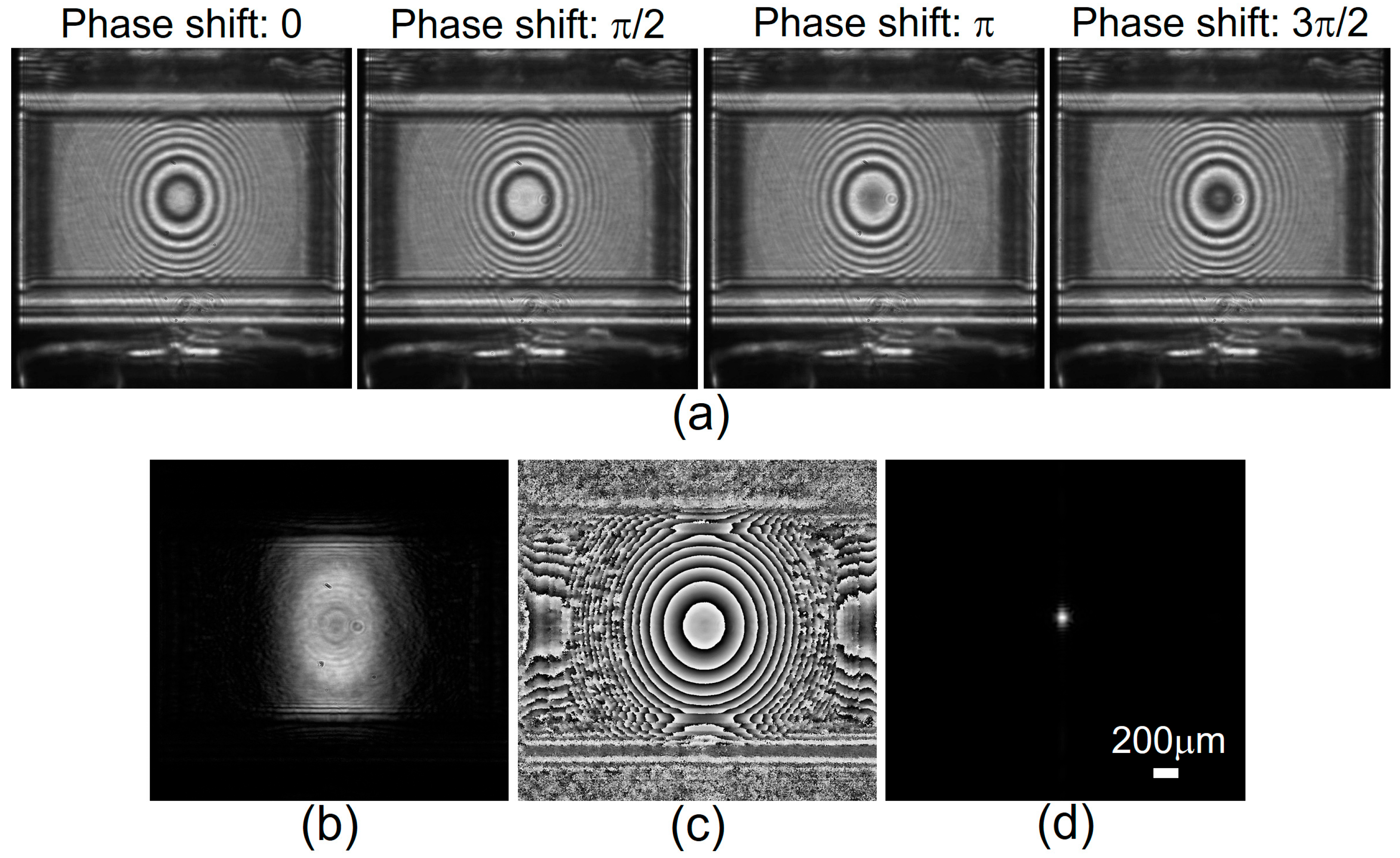
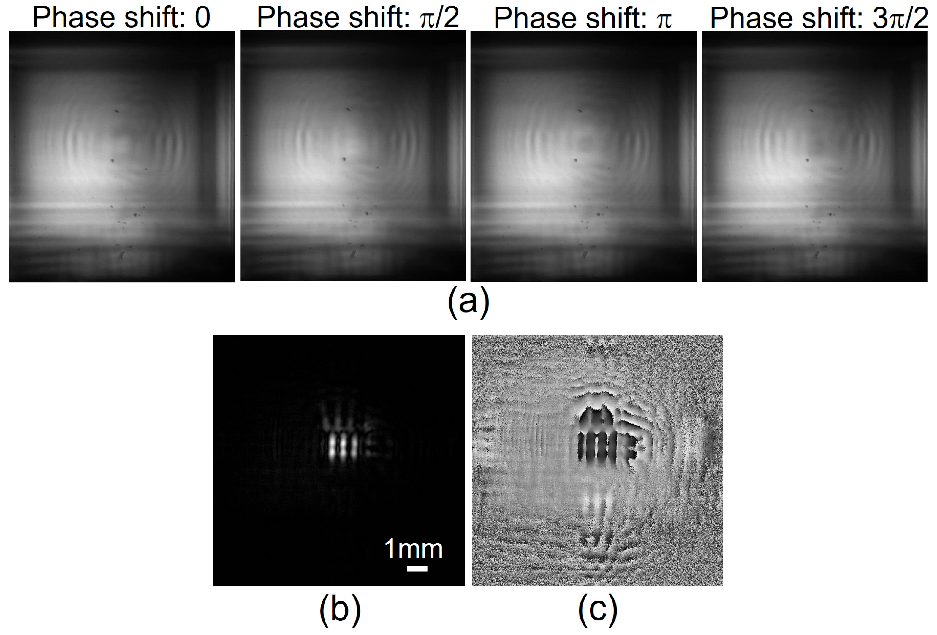
3. Experimental Results

Experiments were conducted to demonstrate the incoherent 3D imaging capability of the developed IDH system. First, I investigated whether horizontally and vertically polarized holograms were superimposed onto the image sensor plane, and then I reconstructed the image of the object illuminated by incoherent light, ensuring there was no blurring due to misalignment. I set an aperture with a diameter of 100 mm as the object. The object was illuminated by a blue light-emitting diode (LED) whose nominal wavelength and full-width at half-maximum were 445 nm and 18 nm, respectively. The LED and object were set on an optical table without an antivibration structure, and the developed IDH optical setup was set on a tripod stand that was put on the ground. TPP-SLMs displayed two Fresnel phase lenses with focal lengths of ∞ and 850 mm, based on the FINCH system with spatial multiplexing. The image sensor recorded four phase-shifted digital holograms sequentially, and then the computer reconstructed the image of the object through the image reconstruction procedure. Figure 3 shows the experimental results. These results indicate that U(x,y) was successfully retrieved from the recorded holograms, and no blurring due to misalignment was seen in either the recorded holograms or the reconstructed image. A focused image of the aperture was successfully obtained. Thus, superimposition of the orthogonally polarized holograms and image reconstruction without blurring were experimentally demonstrated.
Experiments using transmittance and reflective objects were also conducted to confirm the incoherent 3D imaging capability with various recording geometries. A negative USAF1951 test target was set between the LED and the developed IDH optical setup. An aperture was set in front of the group 0, line 6 of the test target. The LED, optical table, and tripod stand were used similarly to the previous experiment. The stripe pattern of group 0, line 6 was recorded as incoherent holograms. Figure 4 shows the experimental results of the USAF1951 test target. Spatially incoherent holograms of the target were recorded, and the focused image was successfully reconstructed. The results confirm that the structure of the object was retrieved through the image reconstruction procedure. Next, a bolt with a length of 10 mm was set as the reflective object. The LED, optical table, and tripod stand were used similarly to the other experiments. The distance between the bolt and the input port of the developed IDH optical setup was 22 mm. LED light was introduced to the bolt, and the light reflected and diffracted from the bolt was recorded as incoherent holograms. After the recording, the object image was reconstructed using the four- and three-step PSI methods to investigate whether the number of recordings could be reduced. Figure 5 shows the experimental results of the bolt. Clear multiple phase-shifted incoherent holograms were obtained, and a focused image of the bolt was reconstructed without blurring. The structure of the object was clearly reconstructed, and a speckle-less image was holographically reconstructed by incoherent holography. The results indicate that the three-step PSI method is applicable to the developed IDH system. Standard deviations were calculated for the intensity images reconstructed with four- and three-step PSI to investigate their image qualities comparatively. Table 1 indicates that random noise was more efficiently suppressed using four-step PSI compared to three-step PSI, although object images were successfully reconstructed by using both PSI methods. Thus, its incoherent 3D imaging capability for transmissive and reflective objects was experimentally demonstrated.

4. Discussion and Conclusions

A compact and portable IDH system in which neither a filter, refractive lens, nor half mirror is required was developed. The filter-free lens-free incoherent digital holographic 3D imaging capability of this IDH system was successfully demonstrated. The light-use efficiency of FINCH systems [45,46,47] can be improved using the developed IDH system because of the removal of the polarization filter. The IDH system is applicable to wavelength- and polarization-multiplexed holographic imaging [42,43,48], and portable, lens-free, multiwavelength, and polarimetric IDH is achievable. By combining the IDH system with single-shot PSI adopting a diffraction grating [49,50,51], single-shot IDH for 3D and 4D (3D + polarization) [38] imaging is also achievable. Single-shot IDH with TPP-SLMs has been experimentally performed with the single-channel off-axis geometry, termed Fourier incoherent single-channel holography (FISCH) [52,53]. It is considered that single-shot IDH with the developed IDH system has the benefits of light-use efficiency and the possibility of single-shot 4D imaging compared with FISCH with TPP-SLMs. The main restriction of the developed IDH system is its field of view. The field of view is determined by the size of the image sensor and the ratio of z1 to z2. In the developed IDH system, there is a limitation in the reduction in z2 for enlarging the field of view. A camera lens will be required for obtaining wide field of view. Then, if a refractive lens is inserted in front of the IDH system with a distance equivalent to the focal length of the refractive lens between the lens and the TPP-SLMs, a portable self-reference DH system [54] without a polarization filter can be constructed, and quantitative phase imaging in 3D space can be realized. It is expected that the developed IDH system will be the basis for a variety of holographic imaging apparatuses, and after the improvements described above, it will be useful for the advanced analyses of specimens in microscopy, as well as machine vision, cameras, telescopes, and healthcare in our daily lives.

Funding

Japan Society for the Promotion of Science (23K26579, 23K17364); Cooperative Research Program of “Network Joint Research Center for Materials and Devices” (20244011); Core Research for Evolutional Science and Technology (JPMJCR23A1).

Institutional Review Board Statement

Not applicable.

Informed Consent Statement

Not applicable.

Data Availability Statement

Data underlying the results presented in this paper are not publicly available at this time but may be obtained from the authors upon reasonable request.

Conflicts of Interest

The author has submitted patent applications for technologies related to the system developed in this work.

References

  1. Gabor, D. A new microscopic principle. Nature 1948, 161, 777–778. [Google Scholar] [CrossRef] [PubMed]
  2. Leith, E.N.; Upatnieks, J. Reconstructed wavefronts and communication theory. J. Opt. Soc. Am. 1962, 52, 1123–1128. [Google Scholar] [CrossRef]
  3. Lohmann, A.W. Reconstruction of vectorial wavefronts. Appl. Opt. 1965, 4, 1667. [Google Scholar] [CrossRef]
  4. Hariharan, P. Optical Holography: Principles, Techniques and Applications; Cambridge University Press: New York, NY, USA, 1996. [Google Scholar]
  5. Kubota, T.; Komai, K.; Yamagiwa, M.; Awatsuji, Y. Moving picture recording and observation of three-dimensional image of femtosecond light pulse propagation. Opt. Express 2007, 15, 14348. [Google Scholar] [CrossRef]
  6. Enloe, L.; Murphy, J.; Rubinstein, C. Bstj briefs hologram transmission via television. Bell Syst. Tech. J. 1966, 45, 335. [Google Scholar] [CrossRef]
  7. Goodman, J.W.; Lawrence, R.W. Digital image formation from electronically detected holograms. Appl. Phys. Lett. 1967, 11, 77–79. [Google Scholar] [CrossRef]
  8. Poon, T.-C. Digital Holography and Three-Dimensional Display; Springer: Berlin, Germany, 2006. [Google Scholar]
  9. Kim, M.K. Digital Holographic Microscopy: Principles, Techniques, and Applications; Springer: New York, NY, USA, 2011. [Google Scholar]
  10. Picart, P.; Li, J.-C. Digital Holography; Wiley: Hoboken, NJ, USA, 2013. [Google Scholar]
  11. Poon, T.-C.; Liu, J.-P. Introduction to Modern Digital Holography with MATLAB®; Cambridge University Press: Cambridge, UK, 2014. [Google Scholar]
  12. Shimobaba, T.; Ito, T. Hardware Acceleration of Computational Holography; Springer: Singapore, 2023. [Google Scholar]
  13. Zhang, Y.; Poon, T.-C. Modern Information Optics wit MATLAB; Cambridge University Press: Cambridge, UK, 2023. [Google Scholar]
  14. Cotte, Y.; Toy, F.; Jourdain, P.; Pavillon, N.; Boss, D.; Magistretti, P.; Marquet, P.; Depeursinge, C. Marker-free phase microscopy. Nat. Photon. 2013, 7, 113–117. [Google Scholar] [CrossRef]
  15. Kakue, T.; Yonesaka, R.; Tahara, T.; Awatsuji, Y.; Nishio, K.; Ura, S.; Kubota, T.; Matoba, O. High-speed phase imaging by parallel phase-shifting digital holography. Opt. Lett. 2011, 36, 4131–4133. [Google Scholar] [CrossRef]
  16. Xia, P.; Awatsuji, Y.; Nishio, K.; Matoba, O. One million fps digital holography. Electron. Lett. 2014, 50, 1693–1695. [Google Scholar] [CrossRef]
  17. Lohmann, A.W. Wavefront reconstruction for incoherent objects. J. Opt. Soc. Am. 1965, 55, 1555. [Google Scholar] [CrossRef]
  18. Peters, P.J. Incoherent holograms with mercury light source. Appl. Phys. Lett. 1966, 8, 209–210. [Google Scholar] [CrossRef]
  19. Sirat, G.; Psaltis, D. Conoscopic holography. Opt. Lett. 1985, 10, 4–6. [Google Scholar] [CrossRef]
  20. Liu, J.-P.; Tahara, T.; Hayasaki, Y.; Poon, T.-C. Incoherent digital holography: A review. Appl. Sci. 2018, 1, 143. [Google Scholar] [CrossRef]
  21. Rosen, J.; Vijayakumar, A.; Kumar, M.; Rai, M.R.; Kelner, R.; Kashter, Y.; Bulbul, A.; Mukherjee, S. Recent advances in selfinterference incoherent digital holography. Adv. Opt. Photon. 2019, 11, 1–66. [Google Scholar] [CrossRef]
  22. Rosen, J.; Alford, S.; Anand, V.; Art, J.; Bouchal, P.; Bouchal, Z.; Erdenebat, M.-U.; Huang, L.; Ishii, A.; Juodkazis, S.; et al. Roadmap on Recent Progress in FINCH Technology. J. Imaging 2021, 7, 197. [Google Scholar] [CrossRef] [PubMed]
  23. Tahara, T.; Zhang, Y.; Rosen, J.; Anand, V.; Cao, L.; Wu, J.; Koujin, T.; Matsuda, A.; Ishii, A.; Kozawa, Y.; et al. Roadmap of incoherent digital holography. Appl. Phys. B 2022, 128, 193. [Google Scholar] [CrossRef]
  24. Rosen, J.; Alford, S.; Allan, B.; Anand, V.; Arnon, S.; Arockiaraj, F.G.; Art, J.; Bai, B.; Balasubramaniam, G.M.; Birnbaum, T.; et al. Roadmap on computational methods in optical imaging and holography. Appl. Phys. B 2024, 130, 166. [Google Scholar] [CrossRef]
  25. Tahara, T.; Shimobaba, T.; Kozawa, Y. Review on imaging and sensing with holography. J. Opt. 2025, in press. [Google Scholar] [CrossRef]
  26. Schilling, B.W.; Poon, T.-C.; Indebetouw, G.; Storrie, B.; Shinoda, K.; Suzuki, Y.; Wu, M.H. Three-dimensional holographic fluorescence microscopy. Opt. Lett. 1997, 22, 1506–1508. [Google Scholar] [CrossRef] [PubMed]
  27. Rosen, J.; Brooker, G. Non-scanning motionless fluorescence three-dimensional holographic microscopy. Nat. Photon. 2008, 2, 190–195. [Google Scholar] [CrossRef]
  28. Bon, P.; Linarès-Loyez, J.; Feyeux, M.; Alessandri, K.; Lounis, B.; Nassoy, P.; Cognet, L. Self-interference 3D superresolution microscopy for deep tissue investigations. Nat. Methods 2018, 15, 449. [Google Scholar] [CrossRef] [PubMed]
  29. Liebel, M.; Pazos-Perez, N.; van Hulst, N.F.; Alvarez-Puebla, R.A. Surface-enhanced Raman Scattering Holography. Nat. Nanotechnol. 2020, 15, 1005–1011. [Google Scholar] [CrossRef] [PubMed]
  30. Kim, M.K. Full color natural light holographic camera. Opt. Express 2013, 21, 9636–9642. [Google Scholar] [CrossRef] [PubMed]
  31. Itoh, K.; Inoue, T.; Yoshida, T.; Ichioka, Y. Interferometric supermultispectral imaging. Appl. Opt. 1990, 29, 1625. [Google Scholar] [CrossRef] [PubMed]
  32. Yoshimori, K. Interferometric spectral imaging for three-dimensional objects illuminated by a natural light source. J. Opt. Soc. Am. A 2001, 18, 765. [Google Scholar] [CrossRef]
  33. Rosen, J.; Brooker, G. Fluorescence incoherent color holography. Opt. Express 2007, 15, 2244–2250. [Google Scholar] [CrossRef] [PubMed]
  34. Naik, D.N.; Pedrini, G.; Takeda, M.; Osten, W. Spectrally resolved incoherent holography: 3D spatial and spectral imaging using a Mach-Zehnder radial-shearing interferometer. Opt. Lett. 2014, 39, 1857–1860. [Google Scholar] [CrossRef] [PubMed]
  35. Rosen, J.; Brooker, G. Digital spatially incoherent Fresnel holography. Opt. Lett. 2007, 32, 912–914. [Google Scholar] [CrossRef]
  36. Katz, B.; Rosen, J. Super-resolution in incoherent optical imaging using synthetic aperture with Fresnel elements. Opt. Express 2010, 18, 962–964. [Google Scholar] [CrossRef] [PubMed]
  37. Tahara, T. Polarization-filterless polarization-sensitive polarization-multiplexed phase-shifting incoherent digital holography (P4IDH). Opt. Lett. 2023, 48, 3881–3884. [Google Scholar] [CrossRef]
  38. Tahara, T. Incoherent digital holography with two polarization-sensitive phase-only spatial light modulators and reduced number of exposures. Appl. Opt. 2024, 63, B24–B31. [Google Scholar] [CrossRef] [PubMed]
  39. Tahara, T. Filter-free lens-free polarimetric incoherent digital holography. J. Opt. 2024, 26, 075707. [Google Scholar] [CrossRef]
  40. Bruning, J.H.; Herriott, D.R.; Gallagher, J.E.; Rosenfeld, D.P.; White, A.D.; Brangaccio, D.J. Digital Wavefront Measuring Interferometer for Testing Optical Surfaces and Lenses. Appl. Opt. 1974, 13, 2693–2703. [Google Scholar] [CrossRef]
  41. Yamaguchi, I.; Zhang, T. Phase-shifting digital holography. Opt. Lett. 1997, 22, 1268–1270. [Google Scholar] [CrossRef] [PubMed]
  42. Tahara, T.; Mori, R.; Kikunaga, S.; Arai, Y.; Takaki, Y. Dual-wavelength phase-shifting digital holography selectively extracting wavelength information from wavelength-multiplexed holograms. Opt. Lett. 2015, 40, 2810–2813. [Google Scholar] [CrossRef] [PubMed]
  43. Tahara, T.; Mori, R.; Arai, Y.; Takaki, Y. Four-step phase-shifting digital holography simultaneously sensing du-al-wavelength information using a monochromatic image sensor. J. Opt. 2015, 17, 125707. [Google Scholar] [CrossRef]
  44. Isomae, Y.; Sugawara, N.; Iwasaki, N.; Honda, T.; Amari, K. Phase-Only Spatial Light Modulator Having High Reflectance, High-Definition Pixels And High Photo-Durability. In Proceedings of the Digital Optical Technologies 2021, Online, 21–25 June 2021; Volume 11788, pp. 191–196. [Google Scholar]
  45. Kelner, R.; Katz, B.; Rosen, J. Optical sectioning using a digital Fresnel incoherent-holography-based confocal imaging system. Optica 2014, 1, 70–74. [Google Scholar] [CrossRef]
  46. Vijayakumar, A.; Kashter, Y.; Kelner, R.; Rosen, J. Coded aperture correlation holography system with improved performance [Invited]. Appl. Opt. 2017, 56, F67–F77. [Google Scholar] [CrossRef] [PubMed]
  47. Choi, K.; Yim, J.; Min, S. Optical defocus noise suppressing by using a pinhole-polarizer in Fresnel incoherent correlation holography. Appl. Opt. 2017, 56, F121–F127. [Google Scholar] [CrossRef] [PubMed]
  48. Tahara, T.; Ishii, A.; Ito, T.; Ichihashi, Y.; Oi, R. Single-shot wavelength-multiplexed digital holography for 3D fluorescent microscopy and other imaging modalities. Appl. Phys. Lett. 2020, 117, 031102. [Google Scholar] [CrossRef]
  49. Zhu, B.; Ueda, K. Real-time wavefront measurement based on diffraction grating holography. Opt. Commun. 2003, 225, 1–6. [Google Scholar] [CrossRef]
  50. Nobukawa, T.; Muroi, T.; Katano, Y.; Kinoshita, N.; Ishii, N. Single-shot phase-shifting incoherent digital holography with multiplexed checkerboard phase gratings. Opt. Lett. 2018, 43, 1698–1701. [Google Scholar] [CrossRef] [PubMed]
  51. Sakamaki, S.; Yoneda, N.; Nomura, T. Single-shot in-line Fresnel incoherent holography using a dual-focus checkerboard lens. Appl. Opt. 2020, 59, 6612–6618. [Google Scholar] [CrossRef]
  52. Kelner, R.; Rosen, J. Spatially incoherent single channel digital Fourier holography. Opt. Lett. 2012, 37, 3723–3725. [Google Scholar] [CrossRef] [PubMed]
  53. Kelner, R.; Rosen, J.; Brooker, G. Enhanced resolution in Fourier incoherent single channel holography (FISCH) with reduced optical path difference. Opt. Express 2013, 21, 20131–20144. [Google Scholar] [CrossRef] [PubMed]
  54. Tahara, T. Self-reference digital holography unit adaptable to optical microscope with light-emitting diode. Opt. Express 2024, 32, 46090–46102. [Google Scholar] [CrossRef]
Figure 1. Schematic of the optical setup of the developed IDH system.
Photonics 12 00167 g001
Figure 2. Photographs of the developed IDH system. (a) Inside of the body containing the developed IDH optical setup, and (b) the developed IDH system set on a tripod stand.
Photonics 12 00167 g002
Figure 3. Experimental results for IDH recording of an aperture. (a) Phase-shifted holograms recorded using an LED. (b) Amplitude and (c) phase distributions on the image sensor plane. (d) Reconstructed image after numerical refocusing. The numerical propagation distance fc was 460 mm.
Photonics 12 00167 g003
Figure 4. Experimental results for a transmissive object. (a) Recorded phase-shifted spatially incoherent holograms. Reconstructed (b) intensity and (c) phase distributions after numerical refocusing. The numerical propagation distance fc was 960 mm.
Photonics 12 00167 g004
Figure 5. Experimental results for a reflective object. (a) Recorded phase-shifted spatially incoherent holograms. (b) Amplitude and (c) phase distributions on the image sensor plane. (d) Amplitude and (e) phase distributions on the object image plane, obtained by four-step PSI and calculated by numerical refocusing. (f) Amplitude and (g) phase distributions, obtained by three-step PSI and calculated by numerical refocusing. The numerical propagation distance fc was 1110 mm.
Photonics 12 00167 g005
Table 1. The standard deviations of the regions in the reconstructed images in Figure 5. Each region is indicated by the red rectangles shown in Figure 5d.
Left Region
(50 × 50 Pixels)
Center Region
(50 × 50 Pixels)
Right Region
(50 × 50 Pixels)
IDH with four-step PSI5.645.585.99
IDH with three-step PSI6.837.207.38
Disclaimer/Publisher’s Note: The statements, opinions and data contained in all publications are solely those of the individual author(s) and contributor(s) and not of MDPI and/or the editor(s). MDPI and/or the editor(s) disclaim responsibility for any injury to people or property resulting from any ideas, methods, instructions or products referred to in the content.

