Wavelength Dependence of Modal Bandwidth of Multimode Fibers for High Data Rate Transmission and Its Implications


Abstract
1. Introduction
2. Multimode Fibers for High Data Rate Transmission
3. Wavelength Dependence of EMB for ‘HDR MMF’ through Monte Carlo Simulation
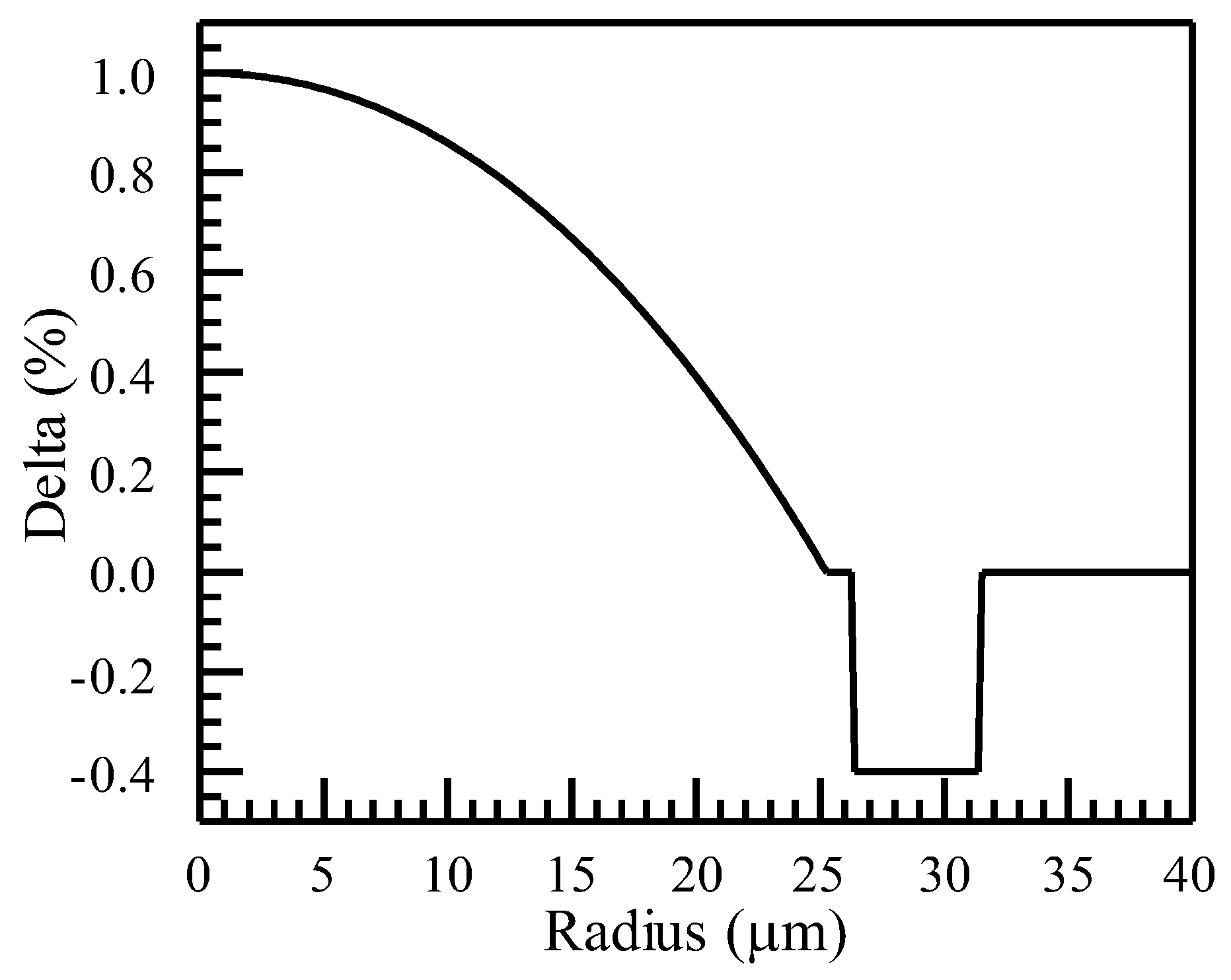
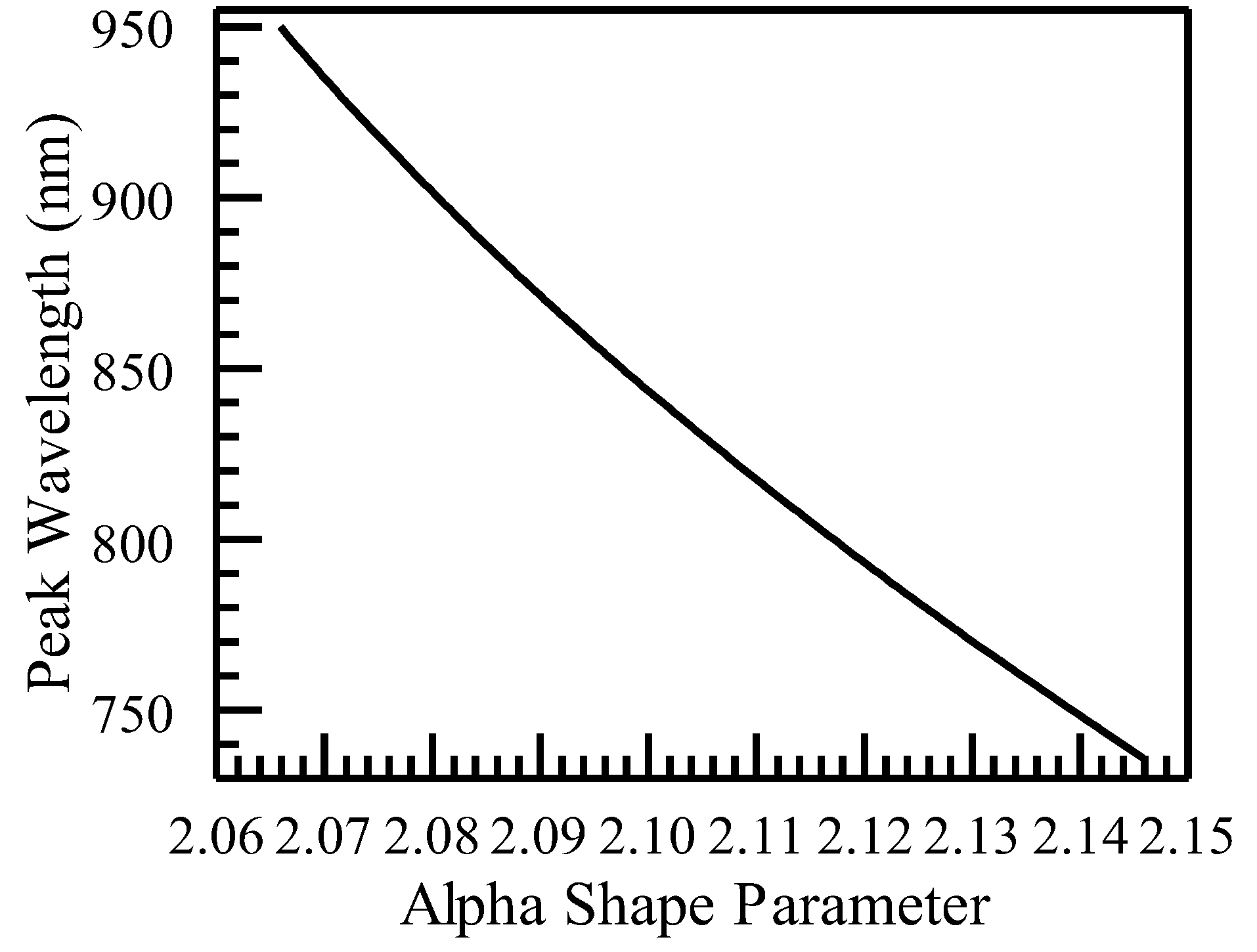
3.1. Generation of Refractive Index Profiles for Monte Carlo Simulation
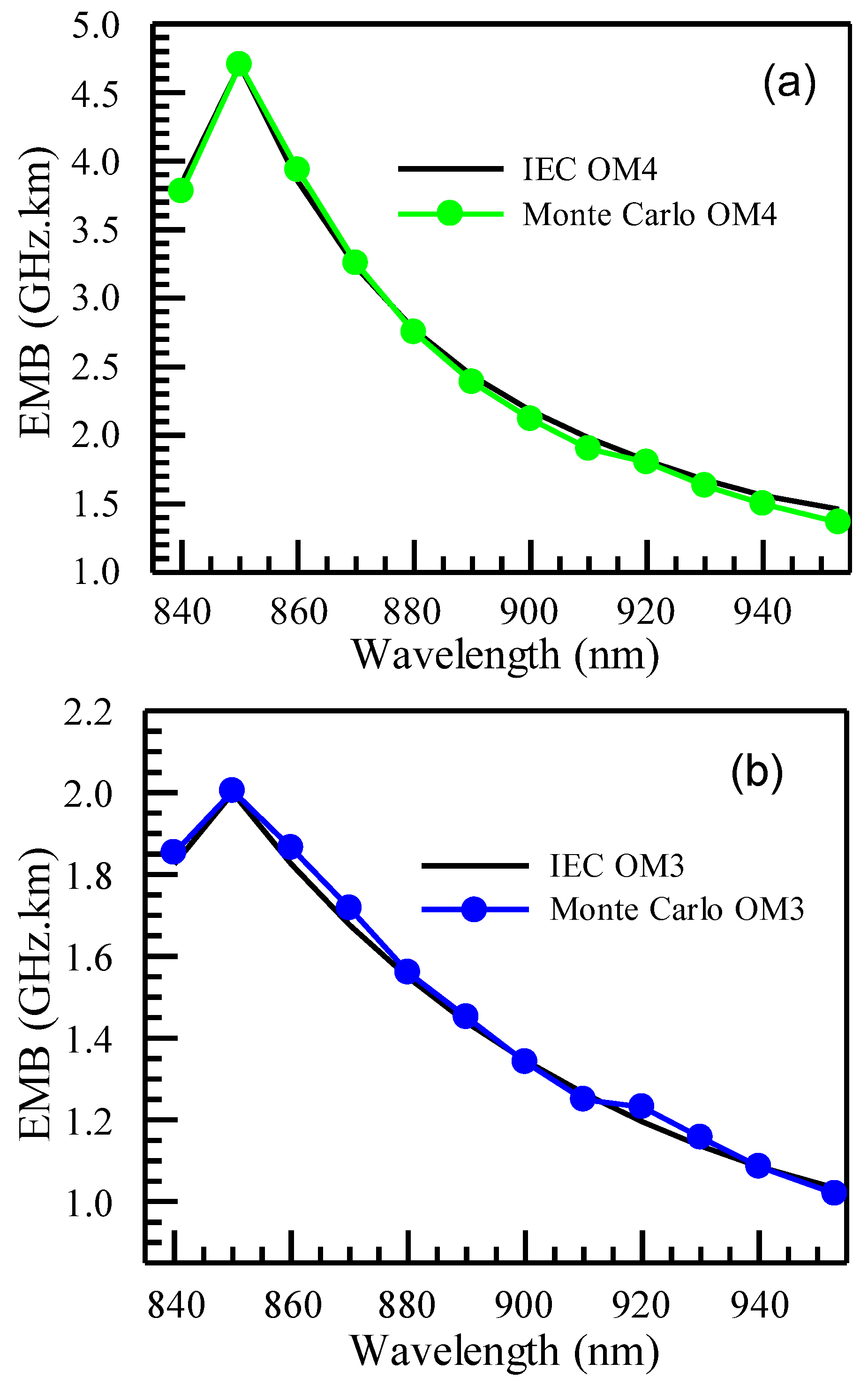
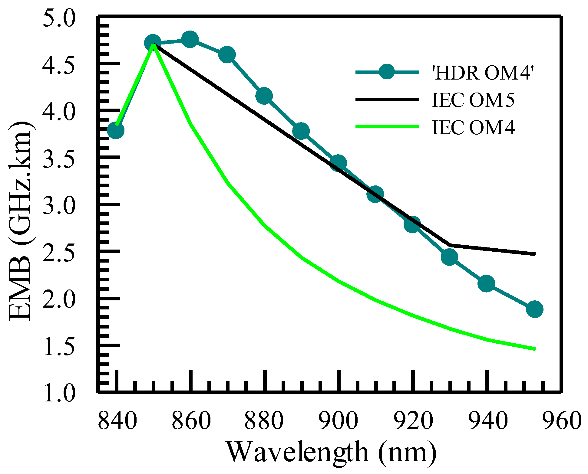
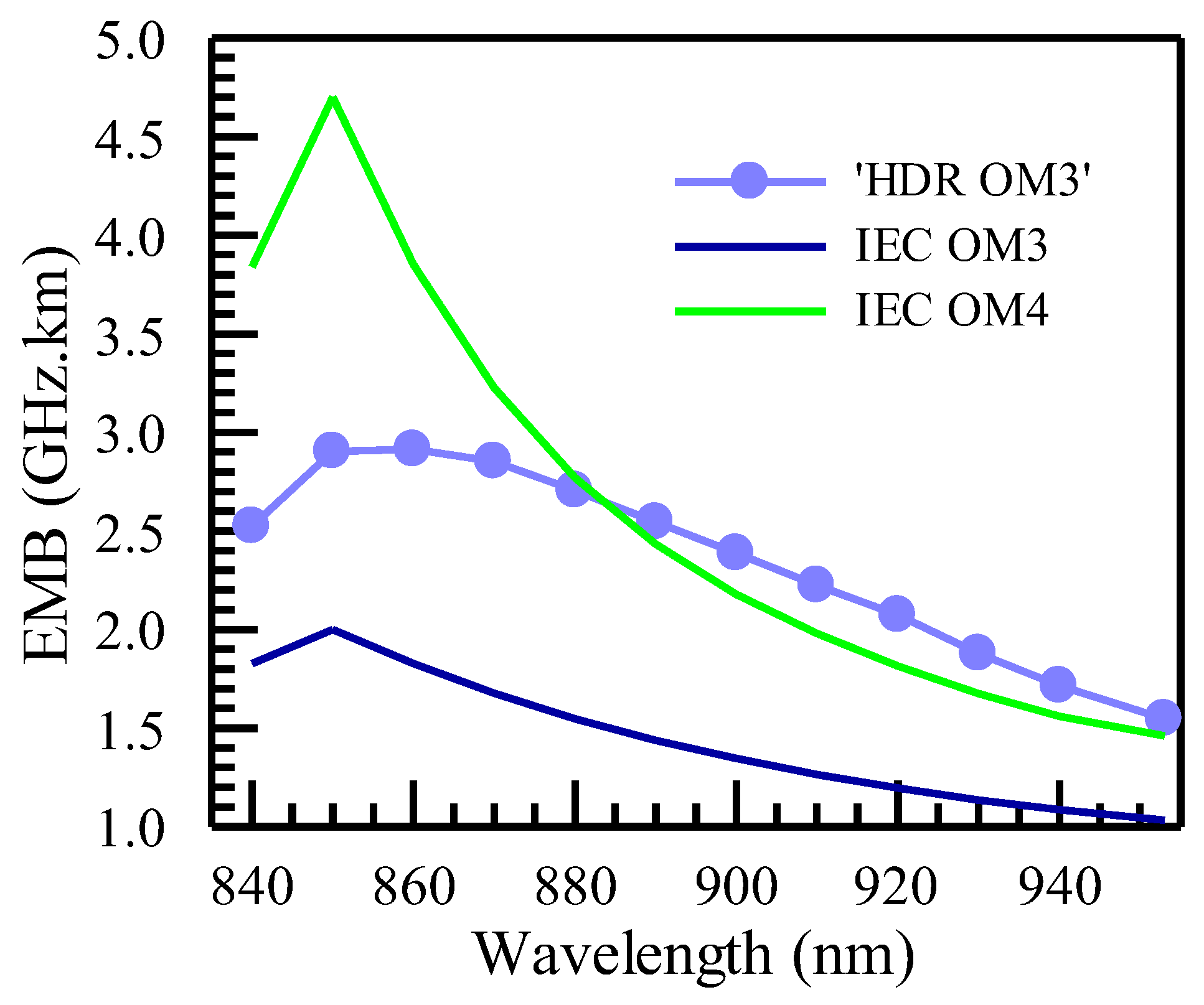
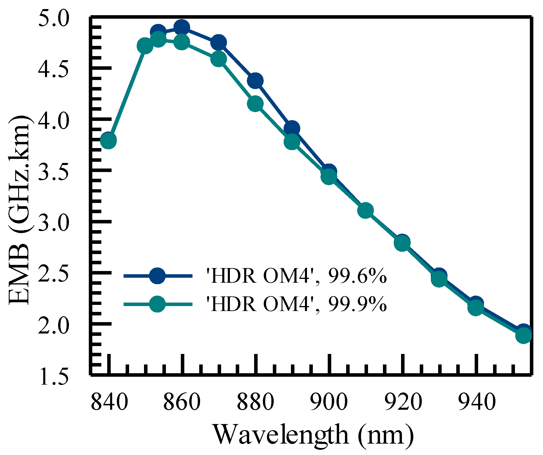
3.2. Wavelength Dependence of EMB of MMFs
4. Link Bandwidth and Transmission Capabilities of Various Applications as Related to the Wavelength Dependence of EMB
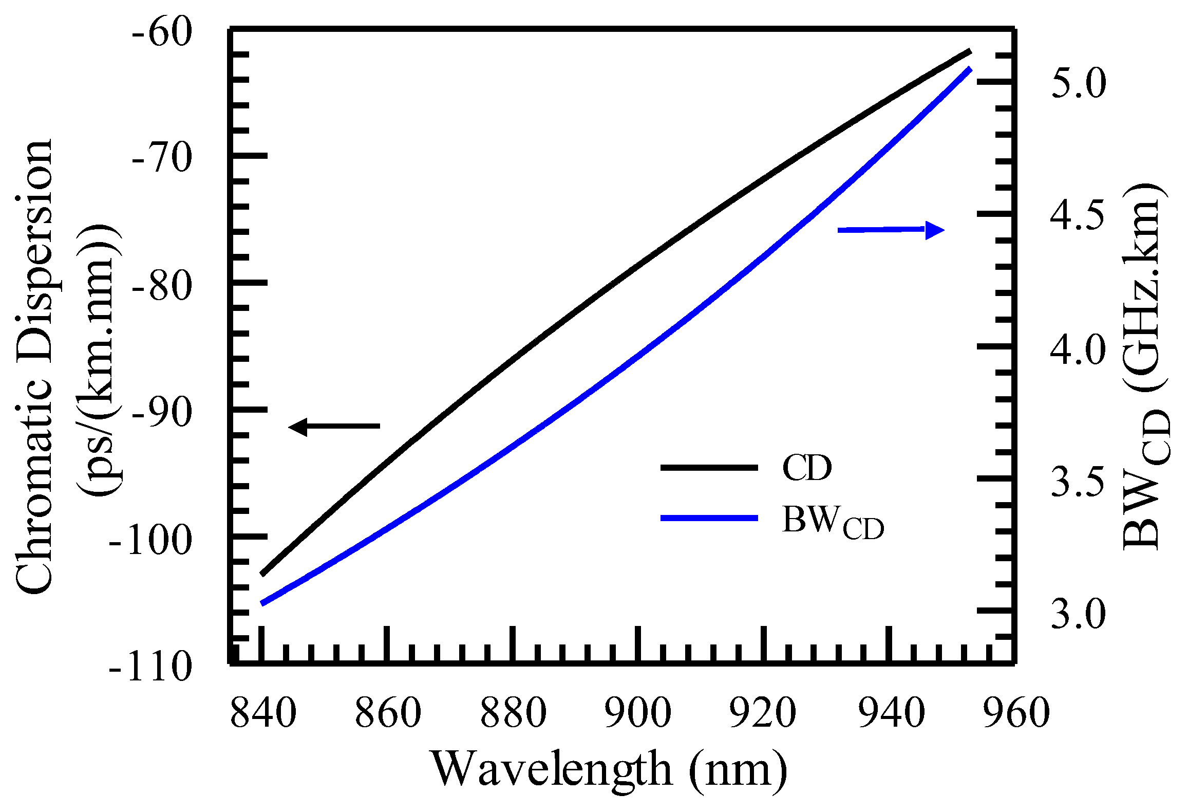
4.1. The Role of Chromatic Dispersion (CD) and Link Bandwidth
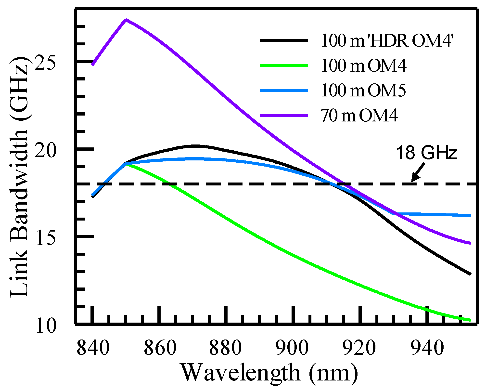
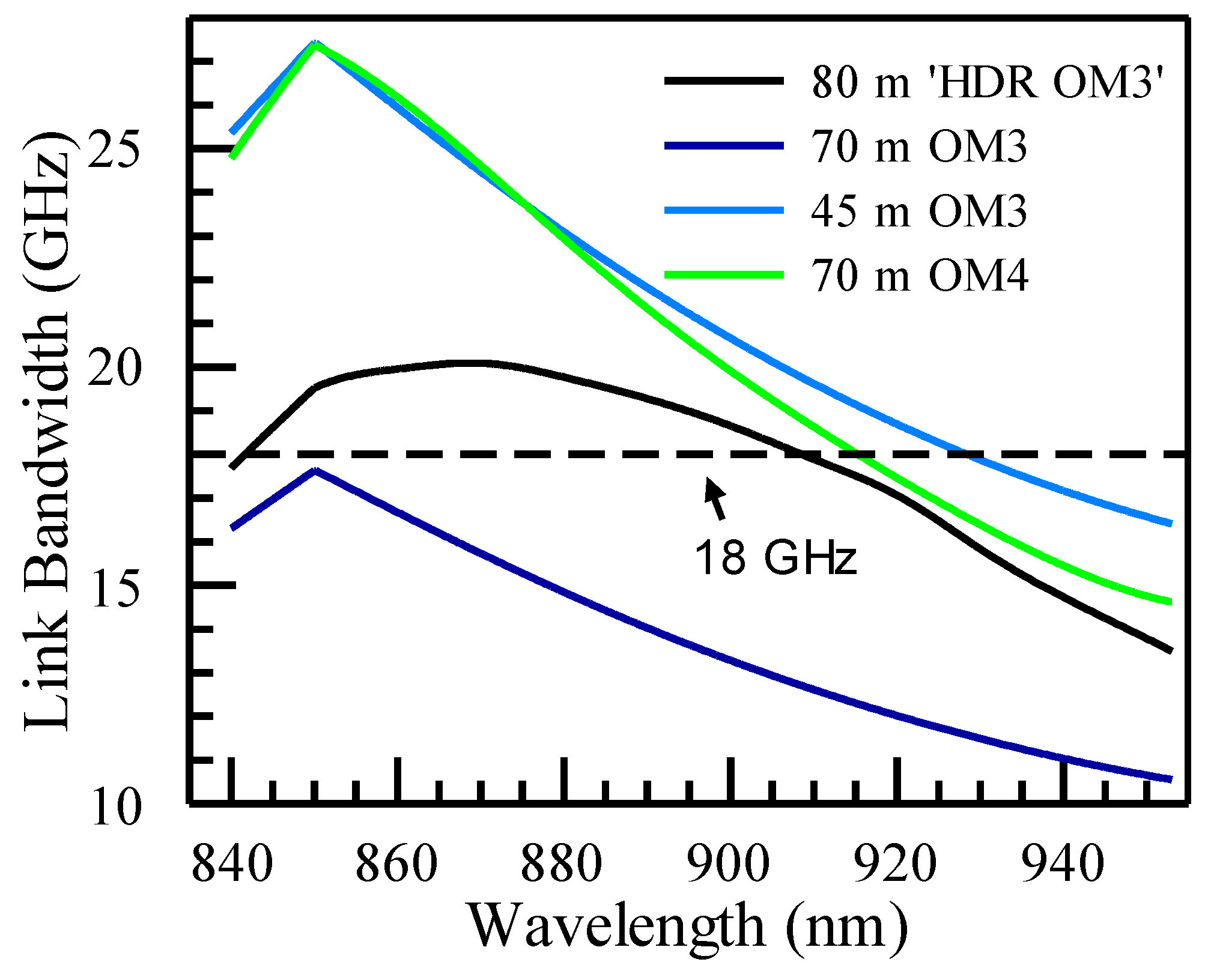
4.2. Link Bandwidths of Various MMFs at Lengths of Interest
4.3. Transmission Reaches for Various Types of Transceivers
4.4. Implications outside 850 nm and 910 nm Wavelength Windows
5. Discussion
- Benefit for the 850 nm wavelength window: By definition, ‘HDR OM3’ and ‘HDR OM4’ are defined at 850 nm and 910 nm wavelengths. However, since we have taken into consideration the limitation of OM3 for 100G-per-lane transmission with a reach of 60 m, we have chosen the 850 nm EMB for ‘HDR OM3’ to support an 80 m reach. This ensures that ‘HDR OM3’ can also benefit 850 nm-only applications. It alleviates the issue of OM3’s reach dropping below 70 m, a distance that many customers have grown accustomed to and around which many data centers have been designed.
- Addressing the wavelength shifting toward 860 nm in 850 nm window: As the VCSEL data rate increases to 100G per lane and will reach 200G per lane very soon, some implementations of VCSELs have shown a shift in the wavelength, more centered around 860 nm instead of 850 nm. The ‘HDR MMFs’ offer the benefit of having enhanced performance for the entire 850–870 nm wavelength window. Taking into account the CD contribution, the link bandwidth over this wavelength range stays above the level at 850 nm, meeting the high bandwidth demands despite the wavelength shift.
- Comparison to OM3 and OM4: One major limitation of OM3 and OM4 is that their EMBs decrease rapidly as the wavelength moves away from 850 nm, particularly when moving toward higher wavelengths up to 910 nm. Even though the 850 nm EMBs of these fibers remain adequate in many cases, the limitation at 910 nm restricts their applications for longer wavelength use, including 860 nm-centered applications and BiDi applications involving 850/910 nm dual wavelengths.
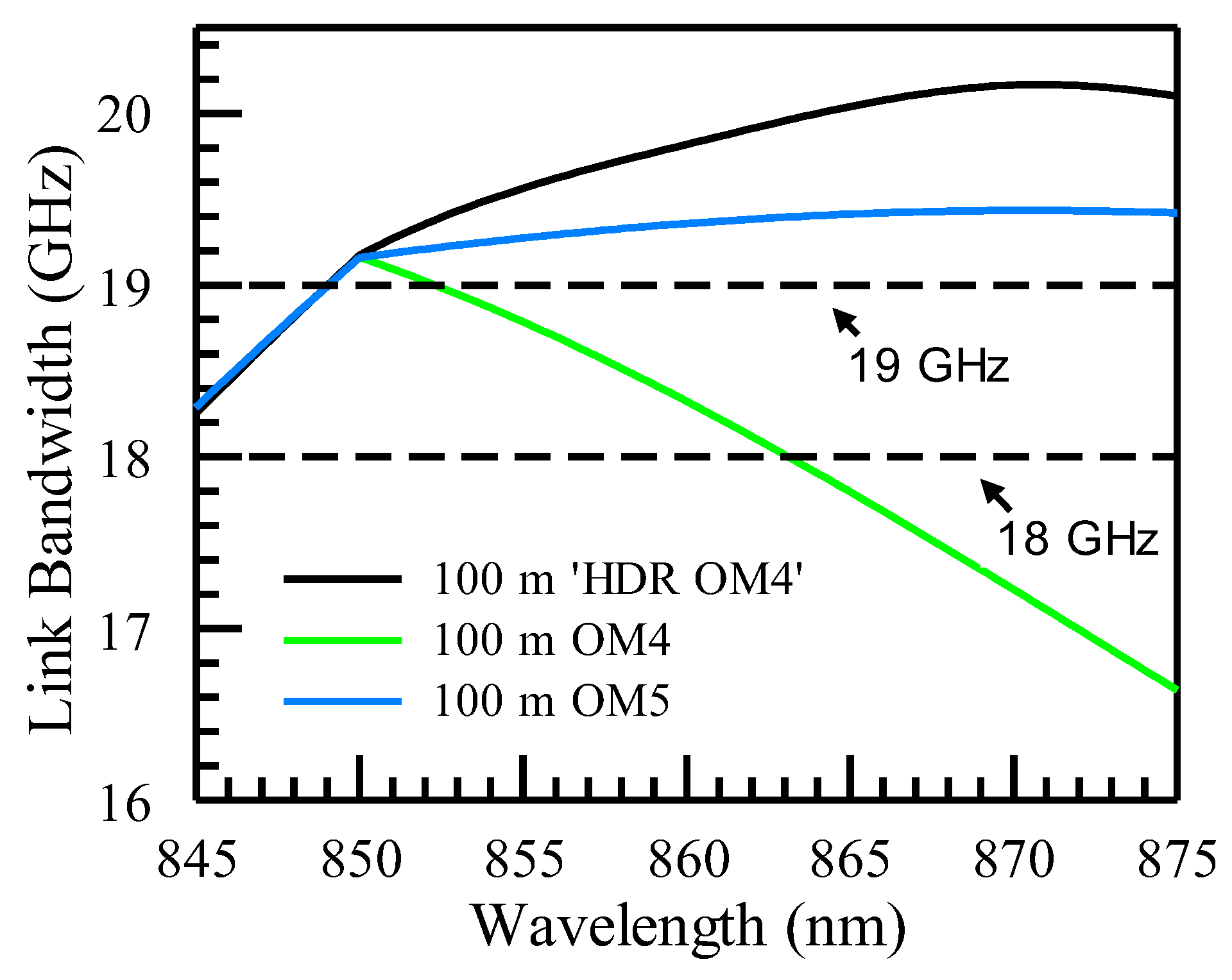
- Enabling VCSELs with more wavelengths: Currently, most VCSELs are implemented at 850 nm and 910 nm, with the exception of SWDM VCSELs, which work up to 953 nm but are so far limited to 100G data rates at the transceiver level. The current study shows that ‘HDR MMFs’ can have uniform link bandwidths from 850 nm to 910 nm. This opens up the feasibility of implementing VCSELs at any wavelength from 850 nm to 910 nm to achieve similar performance.
- Benefits for SWDM applications: even though SWDM applications have not been deployed in large volumes like other types of VCSEL transceivers and have not reached higher data rates, ‘HDR MMFs’ still demonstrate their advantages over OM3 and OM4 by delivering significantly better transmission reaches, although they trail somewhat behind OM5.
- Comparison to OM5: Unlike OM5, which was defined based on EMBs at 850 nm and 953 nm, ‘HDR MMFs’ were defined based on EMBs at 850 nm and 910 nm. ‘HDR OM4’ has the same EMBs as OM5 at both 850 nm and 910 nm. The wavelength dependence study in Section 3 shows that ‘HDR OM4’ has an EMB, from 850 nm to 910 nm, equal to or higher than that of OM5 guided by IEC. This implies that ‘HDR OM4’ can cover all the needs of OM5 from 850 nm to 910 nm and can be a more cost-effective and higher-volume solution for a wide range of applications using the relevant wavelengths.
6. Conclusions
Author Contributions
Funding
Institutional Review Board Statement
Informed Consent Statement
Data Availability Statement
Conflicts of Interest
References
- Chen, X.; Bickham, S.R.; Abbott, J.S.; Coleman, J.D.; Li, M.-J.; Peng, G.D. Multimode fibers for data centers. In Handbook of Optical Fibers; Springer Nature Singapore Pte Ltd.: Berlin/Heidelberg, Germany, 2018; pp. 1–57. [Google Scholar]
- Li, M.-J. MMF for High Data Rate and Short Length Applications. In Proceedings of the Optical Fiber Communication Conference, OFC 2014, San Diego, CA, USA, 24–28 March 2024; pp. 1–3. [Google Scholar]
- Cisco Annual Internet Report (2018–2023) White Paper (Updated: March 9, 2020). Available online: https://www.cisco.com/c/en/us/solutions/executive-perspectives/annual-internet-report/index.html (accessed on 14 July 2024).
- InfiniBand Network Application in DGX Cluster. Available online: https://www.naddod.com/blog/infiniband-network-application-in-dgx-cluster (accessed on 14 July 2024).
- Cisco 40GBASE QSFP Modules Data Sheet. Available online: https://www.cisco.com/c/en/us/products/collateral/interfaces-modules/transceiver-modules/data_sheet_c78-660083.html (accessed on 14 July 2024).
- Terabit BiDi MSA. Available online: https://terabit-bidi-msa.com/ (accessed on 14 July 2024).
- Tatum, J.A.; Gazula, D.; Graham, L.A.; Guenter, J.K.; Johnson, R.H.; King, J.; Kocot, C.; Landry, G.D.; Lyubomirsky, I.; MacInnes, A.N.; et al. VCSEL-based interconnects for current and future data centers. J. Light. Technol. 2015, 33, 727–732. [Google Scholar] [CrossRef]
- Shortwave Wavelength Division Multiplexing (SWDM) Alliance. Available online: https://www.swdm.org/ (accessed on 14 July 2024).
- Chorchos, L.; Ledentsov, N.; Makarov, O.; Shchukin, V.A.; Kalosha, V.; Turkiewicz, J.P. Multi Aperture High Power 100G Single Mode 850nm VCSEL for Extended Reach 800G Ethernet. In Proceedings of the Optical Fiber Communications Conference and Exhibition (OFC), San Diego, CA, USA, 5–9 March 2023; pp. 1–3. [Google Scholar]
- Zuo, T.; Zhang, T.; Zhang, S.; Liu, L. 850-nm VCSEL-based single-lane 200-Gbps PAM-4 transmission for datacenter intra-connections. IEEE Photonics Technol. Lett. 2021, 33, 1042–1045. [Google Scholar] [CrossRef]
- Murty, M.V.R.; Wang, J.; Jiang, S.; Dolfi, D.; Wang, T.K.; Vaughan, D.; Feng, Z.; Leong, N.; Sridhara, A.; Joyo, S.T.; et al. Toward 200G per Lane VCSEL-based Multimode Links. In Proceedings of the Optical Fiber Communication Conference (OFC) 2024, San Diego, CA, USA, 24–28 March 2024; Technical Digest Series; Paper M2D.3; Optica Publishing Group: Washington, DC, USA, 2024. [Google Scholar]
- Tirelli, S.; Corti, E.; Duda, E.; Pissis, A.; Hönl, S.; Hoser, M.; Paul, M.; Zibik, E. Lithographic Aperture VCSELs Enabling Beyond 100G Datacom Applications. In Proceedings of the Optical Fiber Communication Conference (OFC) 2024, San Diego, CA, USA, 24–28 March 2024; Technical Digest Series; Paper M2D.1; Optica Publishing Group: Washington, DC, USA, 2024. [Google Scholar]
- Wettlin, T.; Lin, Y.; Stojanovic, N.; Calabrò, S.; Wang, R.; Zhang, L.; Kuschnerov, M. 200 Gb/s VCSEL transmission Using 60 m OM4 MMF and KP4 FEC for AI computing clusters. arXiv 2024, arXiv:2403.17275. [Google Scholar]
- IEEE Standard for Ethernet—Amendment 3: Physical Layer Specifications and Management Parameters for 100 Gb/s, 200 Gb/s, and 400 Gb/s Operation over Optical Fiber using 100 Gb/s Signaling. Available online: https://standards.ieee.org/ieee/802.3db/10283/ (accessed on 14 July 2024).
- TIA-492AAAE; Detail Specification for 50-µm Core Diameter/125-µm Cladding Diameter Class 1a Graded-Index Multimode Optical Fibers with Laser-Optimized Bandwidth Characteristics Specified for Wavelength Division Multiplexing. TIA: Arlington, VA, USA, 2016.
- IEC 60793-2-10:2019; Optical Fibres—Part 2–10: Product Specifications—Sectional Specification for Category A1 Multimode Fibres. Edition 7.0. IEC: Geneva, Switzerland, 2019.
- Dong, H.; Chen, X. The Road to 800G with Multimode Fiber. Corning Incorporated. Available online: https://www.corning.com/catalog/coc/documents/articles/CO8000_Article_Road%20to%20800G%20multimode%20fiber.pdf (accessed on 14 July 2024).
- Chen, H.; Wang, C.; Chen, X.; Dong, H.; Bullock, Z. Optimized Multimode Fiber for 100G/land and BiDi technologies. In Proceedings of the 2023 China Communication Academic Annual Conference, Dalian, China, 10–12 August 2023. [Google Scholar]
- Chen, X.; Dong, H.; Chen, H.; Mu, J.; Zheng, L.; Yang, S.; Hurley, J.E.; Wood, W.A.; Bullock, Z.; Li, M.-J. Concept of BiDi Optimized OM4 Multimode Fiber for High Date Rate Short Reach VCSEL Transmission. In Proceedings of the 2023 Opto-Electronics and Communications Conference (OECC), Shanghai, China, 2–6 July 2023; pp. 1–5. [Google Scholar]
- Chen, X.; Dong, H.; Huang, O.; Mu, J.; Chen, H.; Hurley, J.E.; Bullock, Z.; Li, M.-J. Concept of OM3 Multimode Fiber Optimized for 100G/lane and BiDi Based VCSEL Transmission. In Proceedings of the 2024 Opto-Electronics and Communications Conference (OECC), Melbourne, Australia, 30 June–4 July 2024. Paper #45. [Google Scholar]
- Corning® ClearCurve® OM3 XT and OM4 XT Optical Fibers—Product Information. Available online: https://www.corning.com/media/worldwide/coc/documents/Fiber/product-information-sheets/PI-1568.pdf (accessed on 14 July 2024).
- LaserWave® Dual-Band OM4+ Multimode Optical Fiber. Available online: https://fiber-optic-catalog.ofsoptics.com/LaserWave-Dual-Band-OM4-Multimode-Optical-Fiber-10033 (accessed on 14 July 2024).
- Li, M.-J.; Tandon, P.; Bookbinder, D.C.; Bickham, S.R.; Wilbert, K.A.; Abbott, J.S.; Nolan, D.A. Designs of bend-insensitive multimode fibers. In Proceedings of the 2011 Optical Fiber Communication Conference and Exposition and The National Fiber Optic Engineers Conference, Los Angeles, CA, USA, 6–10 March 2011; pp. 1–3. [Google Scholar]
- Bourdine, A.V.; Praporshchikov, D.E.; Yablochkin, K.A. Investigation of defects of refractive index profile of silica graded-index multimode fibers. Proc. SPIE 2011, 7992, 799206. [Google Scholar]
- Lenahan, T.A. Calculation of modes in an optical fiber using the finite element method and EISPACK. Bell Syst. Tech. J. 1983, 62, 2663–2694. [Google Scholar] [CrossRef]
- IEC 60793-1-49; Optical Fibres—Part 1-49: Measurement Methods and Test Procedures—Differential Mode Delay. Edition 3.0. IEC: Geneva, Switzerland, 2018.
- Bottacchi, S. Multi-Gigabit Transmission over Multimode Optical Fibre: Theory and Design Methods for 10 GbE Systems; John Wiley & Sons, Ltd: Hoboken, NJ, USA, 2006. [Google Scholar]
- Li, M.-J.; Li, K.; Chen, X.; Mishra, S.K.; Juarez, A.A.; Hurley, J.E.; Stone, J.S.; Wang, C.-H.; Cheng, H.-T.; Wu, C.-H.; et al. Single-Mode VCSEL Transmission for Short Reach Communications. J. Lightwave Technol. 2021, 39, 868–880. [Google Scholar] [CrossRef]
- Ledentsov, N.N.; Makarov, O.Y.; Shchukin, V.A.; Kalosha, V.P.; Ledentsov, N.; Chrochos, L.; Sanayeh, M.B.; Turkiewicz, J.P. High Speed VCSEL Technology and Applications. J. Lightwave Technol. 2022, 40, 1749–1763. [Google Scholar] [CrossRef]
- Understanding the Differences Between OM4 and OM5 Multimode Fiber. Available online: https://www.cisco.com/c/en/us/products/collateral/interfaces-modules/transceiver-modules/diff-om4-om5-multimode-fiber-wp.html (accessed on 14 July 2024).
- Available online: https://blog.siemon.com/infrastructure/om5-no-reach-advantage-cisco-multimode-transceivers#:~:text=Most%20of%20Cisco's%20multimode%20transceivers,realize%20significant%20benefits%20from%20OM5 (accessed on 14 July 2024).
- Chang, Y.-C.; Coldren, L.A. Optimization of VCSEL structure for high-speed operation. In Proceedings of the 2008 IEEE 21st International Semiconductor Laser Conference, Sorrento, Italy, 14–18 September 2008; pp. 159–160. [Google Scholar]


| MMF Solution | EMB @ 850 nm (MHz·km) | EMB @ 910 nm (MHz·km) | Reach for 800G BiDi (m) |
|---|---|---|---|
| ‘HDR OM3’ | 2890 | 2220 | 80 |
| ‘HDR OM4’ | 4700 | 3100 | 100 |
| Transceiver Protocol | MSA/Standard | Transmission Reach (m) | ||||
|---|---|---|---|---|---|---|
| OM3 | OM4 | OM5 | ‘HDR OM3’ | ‘HDR OM4’ | ||
| 400G SR4 | IEEE 802.3db | 60 | 100 | 100 | 80 | 100 |
| 800G SR8 | IEEE 802.3df | 60 | 100 | 100 | 80 | 100 |
| 800G SR4.2 | Terabit BiDi MSA | 45 | 70 | 100 | 80 | 100 |
| Transceiver Protocol | MSA/Standard | Reach (m) | ||||
|---|---|---|---|---|---|---|
| OM3 | OM4 | OM5 | ‘HDR OM3’ | ‘HDR OM4’ | ||
| 25G SR | IEEE 802.3by | 70 | 100 | 100 | 87 | 100 |
| 100G SR4 | IEEE 802.3bm | 70 | 100 | 100 | 87 | 100 |
| 400G SR8 | IEEE 802.3cm | 70 | 100 | 100 | 87 | 100 |
| 400G SR4.2/100G BiDi | IEEE 802.3cm/proprietary | 70 | 100 | 150 | 120 | 150 |
| 100G SWDM4 | SWDM MSA | 75 | 100 | 150 | 112 | 130 |
Disclaimer/Publisher’s Note: The statements, opinions and data contained in all publications are solely those of the individual author(s) and contributor(s) and not of MDPI and/or the editor(s). MDPI and/or the editor(s) disclaim responsibility for any injury to people or property resulting from any ideas, methods, instructions or products referred to in the content. |
© 2024 by the authors. Licensee MDPI, Basel, Switzerland. This article is an open access article distributed under the terms and conditions of the Creative Commons Attribution (CC BY) license (https://creativecommons.org/licenses/by/4.0/).
Share and Cite
Chen, X.; Dong, H.; Chen, H.; Hurley, J.E.; Bullock, Z.D.; Li, M.-J. Wavelength Dependence of Modal Bandwidth of Multimode Fibers for High Data Rate Transmission and Its Implications. Photonics 2024, 11, 667. https://doi.org/10.3390/photonics11070667
Chen X, Dong H, Chen H, Hurley JE, Bullock ZD, Li M-J. Wavelength Dependence of Modal Bandwidth of Multimode Fibers for High Data Rate Transmission and Its Implications. Photonics. 2024; 11(7):667. https://doi.org/10.3390/photonics11070667
Chicago/Turabian StyleChen, Xin, Hao Dong, Hao Chen, Jason E. Hurley, Zoren D. Bullock, and Ming-Jun Li. 2024. "Wavelength Dependence of Modal Bandwidth of Multimode Fibers for High Data Rate Transmission and Its Implications" Photonics 11, no. 7: 667. https://doi.org/10.3390/photonics11070667
APA StyleChen, X., Dong, H., Chen, H., Hurley, J. E., Bullock, Z. D., & Li, M.-J. (2024). Wavelength Dependence of Modal Bandwidth of Multimode Fibers for High Data Rate Transmission and Its Implications. Photonics, 11(7), 667. https://doi.org/10.3390/photonics11070667