Abstract
With off-axis reflection systems with specific distortion values serving as objectives or collimators, it is possible to compensate and correct for spectral line bending in spectroscopic instruments. However, there is limited research on the precise control of distortion, which poses particular challenges in large field-of-view optical systems. This paper presents a method for controlling distortion in off-axis reflection systems. Based on Seidel aberration theory and the relationship between distortion wavefront error and primary ray error, we construct objective functions with structural constraints and aberration constraints. The initial structure with specific distortion values is then solved using a differential evolution algorithm. The effectiveness and reliability of this method are verified through the design of an off-axis three-reflection system. The method provided in this study facilitates the design of remote sensing instruments.
1. Introduction
The imaging spectrometer is based on the theory of spectral analysis of substances. While obtaining the two-dimensional spatial image of the target, it acquires the spectral information of the ground elements corresponding to the pixels. The combination of two-dimensional spatial information with one-dimensional spectral information yields an image cube, which has irreplaceable advantages in monitoring dynamic changes in the Earth’s environment [1,2]. The imaging spectrometer consists of a front-end telescope system and a spectral imaging system. The spectral imaging system includes spectral elements, slits, collimators, and focusing mirrors. Off-axis reflective optical systems can simultaneously achieve long focal lengths, wide fields of view, and high imaging quality. Compared to refractive optical systems, they have advantages such as achromatic aberration-free performance, flexible layout, and low sensitivity to temperature and pressure changes. Therefore, they are widely used in spectrometer instruments [3,4,5,6,7,8]. Due to the non-principal section dispersion caused by the spectral elements, the monochromatic images formed exhibit spectral line curvature, which is particularly pronounced in wide-field spectrometer instruments. This can significantly affect the subsequent data application.
Distortion, as a special type of aberration, does not affect the clarity of the image but causes deformation [9]. The spectral line curvature in spectrometer instruments resembles the radial distortion of imaging systems. Therefore, introducing specific distortion values when designing the front-end telescope system and collimating (converging) mirror can balance the spectral line curvature caused by dispersion elements, thereby achieving images with constant resolution [10]. Distortion control is particularly challenging in the design of wide-field optical systems. In the field of off-axis reflective system design, Meng’s group [11] achieved an ultra-wide field of view of 80° × 4° with distortion as high as 28.77% by leveraging the TMA (Three Mirrors Anastigmatic) symmetric property and introducing free-form surfaces. On the other hand, Cao’s group [12] utilized the theory of nodal aberration and genetic algorithms to determine the initial configuration of the off-axis system. They designed an off-axis three-mirror optical system with a field of view of 3° × 4°, achieving a distortion reduction to 1.84%. Currently, there is relatively little research on precisely controlling distortion, often relying on image processing or complex surface design for distortion control in later stages.
Currently, mainstream optical design software utilizes the Damped Least Squares (DLS) method as the optimization algorithm [13,14]. However, this algorithm is prone to getting stuck in local minima, resulting in design outcomes deviating from the global optimum. Additionally, optical design software often relaxes constraints on distortion during aberration balancing to enhance image quality. Ignoring distortion control in the initial design phase may lead to unacceptable levels of distortion after achieving imaging quality standards [15]. This could necessitate correcting distortion using complex surface shapes, thereby reducing optimization efficiency. Therefore, selecting an initial structure that meets the requirements is crucial for optical system design.
This paper derives the relationship between distortion wavefront error and primary ray error under coaxial conditions and studies the third-order distortion characteristics of off-axis pupils. Based on the required distortion size at the marginal field and solving for the wavefront coefficient W311, Seidel aberrations are calculated by analyzing the paraxial ray information on each surface. An error evaluation function is established, composed of weighted aberrations and defined constraints, to meet configuration requirements. A smaller error function indicates a structure closer to the target solution. The differential evolution algorithm is employed to minimize the error function, thus finding an initial structure with specific distortion values. Distortion is then constrained and further optimized using commercial optical design software CODE V [16].
2. Methods
2.1. Analysis of Third-Order Distortion Characteristics
Primary Wave Aberration describes the optical path difference between the actual wavefront and the ideal wavefront [17]. In traditional rotationally symmetric optical systems, wave aberrations are typically represented by the basic parameters H, ρ, and Hρcos θ, as shown in Figure 1a. The distortion being one of the five major aberrations, denoted by W311. Errors generated by primary rays can also be used to represent distortion. As shown in Equation (3), distortion only affects errors in primary rays parallel to the field of view and is independent of the pupil position. Therefore, for a given field angle, all rays within the pupil converge to the same ‘incorrect’ position, yet still produce a clear image.
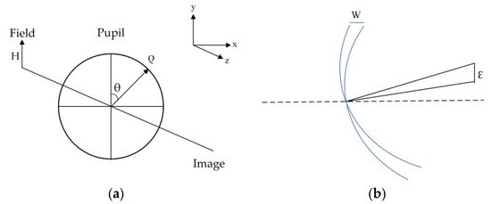
Figure 1.
(a) Schematic to describe primary aberrations; (b) Distortion wavefront error and primary ray error.
H and ρ represent normalized field coordinates and pupil coordinates, respectively, θ is the angular difference between H and ρ, j, n, and m are non-negative integers, ε denotes the error of the primary ray, F is an approximation of the F-number, y is the ideal position of the primary ray on the image plane, and y′ is the actual position of the primary ray on the image plane. Distortion as an aberration is a wavefront error and an associated ray error at the image. The effect can be illustrated with just the chief ray as shown below in Figure 1b.
From coaxial reflective systems to off-axis unobstructed reflective systems, there are generally two approaches: aperture off-axis and field offset. Aperture off-axis is commonly used in TMA optical systems where the primary mirror serves as the aperture. Due to the absence of a common rotationally symmetric axis, the characterization of aberrations becomes complex. To address this challenge, the normalized pupil eccentricity vector is introduced for description. The principle of aperture off-axis is illustrated in Figure 2.
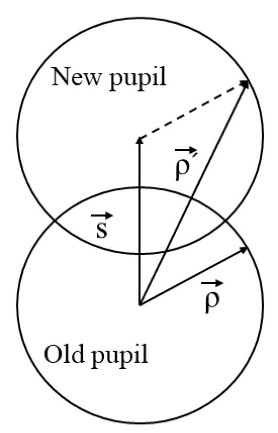
Figure 2.
The schematic diagram of the pupil change after the aperture is moved.
For off-axis systems with aperture displacement, when the aperture shifts, the optical axis (OAR) also shifts accordingly. However, the aberrations on the system’s image plane are still the sum of aberrations caused by each surface. There are no new types of aberrations introduced, and the wave aberration coefficients remain the same as those for coaxial systems. The only difference is that different types of aberrations are coupled together. The representation of third-order distortion is as follows [18]:
where “*” denotes correlation with the Optical Axis Reference (OAR) [11]. From Equation (5), it can be observed that, during the coaxial phase, after correcting the first four monochromatic aberrations, when the aperture is off-axis, the third-order distortion will degrade to coaxial form. Therefore, in designing coaxial reflection systems, we set the coefficients of the first four monochromatic aberrations to zero and solve for the corresponding distortion coefficients based on the required distortion magnitude. The next section will analyze Seidel aberrations and establish their relationship with system structural parameters.
2.2. Calculating Seidel Aberrations
We commence the initial design by constructing a coaxial structure consisting of three quadratic surfaces. The layout diagram of the three-mirror system is depicted in Figure 3, with the aperture stop positioned on the primary mirror (M1). To calculate the overall Seidel aberrations of the system, it is necessary to determine the ray heights, invariant refractive indices, and incident and refracted angles before and after refraction for each paraxial surface. Figure 3a,b, respectively, provide schematic diagrams illustrating the ray tracing of the primary and marginal rays in the coaxial three-mirror structure. For the primary rays, denotes the height relative to the optical axis on the i surface, while represents the angle relative to the optical axis on the cth surface. Similarly, for the marginal rays, and have the same significance. The variable denotes the distance between mirrors.
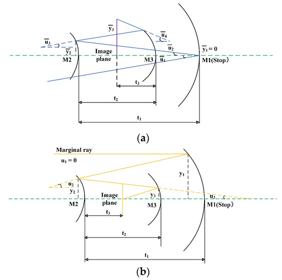
Figure 3.
(a) Principal ray tracing diagram; (b) Edge ray tracing diagram.
In paraxial ray tracing, light rays can be transmitted and transformed through a series of optical components such as lenses, mirrors, etc. The Ray Transfer Matrix (RTM) represents the effects of optical elements as matrix multiplication, thereby simplifying the calculation of ray transfer. It can be algebraically expressed as follows:
In the context of the equation, and denote the heights of the incident and reflected rays on the mirror surface, while and represent the angles of incidence and reflection. and denote the refractive indices of the incident and reflected rays upon entry and reflection from the mirror, respectively. ϕ signifies the optical power of the mirror surface.
For a given paraxial ray, we can represent its state using a column vector, which includes information about the ray’s height and angle of incidence at each refractive surface. The principal ray can be represented as follows:
When conducting paraxial ray tracing within an optical system, we employ transfer matrices and refraction matrices to compute the ray’s state subsequent to traversing the succeeding surface. The transfer matrix establishes the connection between the incident ray’s vector at point 1 and the refracted vector at point 2. The transfer matrix can be expressed as follows:
Similarly, refraction matrix describes the refractive relationship of a ray as it traverses an optical surface. It relates the vector information of the incident ray at point to the vector information of the refracted ray on the same surface. The refraction matrix can be expressed as follows:
By combining the defined paraxial ray vector with transfer matrices and refraction matrices, we can calculate the height and angle information of the paraxial ray on the next surface:
For marginal rays, the computation in paraxial ray tracing is similar to that of principal rays. Since the paraxial angle and the height of principal rays are both zero, the ray heights and paraxial angles of the two characteristic rays on each surface can be calculated as follows:
According to Seidel aberration theory, the results of paraxial ray tracing in rotationally symmetric optical systems can be described by five monochromatic aberrations. These include spherical aberration (), coma (), astigmatism (), Petzval field curvature (), and distortion (). In the case of non-spherical surfaces, Seidel aberrations are the sum of spherical and non-spherical components, expressed as follows:
In this context, a serves as a constant coefficient, while and , respectively, denote the refractive invariants of the marginal and principal rays. The term k indicates the conic coefficient, c signifies the curvature of the mirror, and L represents the Lagrangian invariant of the system. Their calculation formulas are as follows:
When the marginal ray height and the angle of incidence are determined, the five aberration coefficients can be expressed as complex functions of the curvature radius (i = 1, 2, 3), conic coefficient (i = 1, 2, 3), and mirror-to-surface distance (i = 1, 2). Their implicit expressions are as follows:
Based on the aforementioned aberration analysis, an error function F is established to evaluate the initial performance of the optical system’s structure. This error function sets = === 0, where indicates the required distortion inversion value, and represents the true value calculated according to the system’s structural parameters. Additionally, constraints are added based on the first-order parameters of the system. The error function is expressed as follows:
‖ represents the absolute value operator, while (i = 1,2, …, 6) denotes the corresponding weight values for each item, which are set according to system configuration requirements. Spherical aberration and comatic aberration are the two most significant aberrations in off-axis systems; thus, their weights can be set to higher values. A smaller value of error function F indicates that the initial structure is closer to the desired one. The next task is to minimize the 8-dimensional error function F through algorithms to find suitable initial structural parameters.
2.3. Using the Differential Evolution Algorithm to Search for the Initial Structure
The inspiration for the differential evolution (DE) algorithm is derived from the evolutionary processes observed in nature, emulating mechanisms such as natural selection, crossover, and mutation. These mechanisms have been proven highly effective in nature for searching and adapting to the environment. By applying these mechanisms to mathematical models, a population-based optimization algorithm is formed. DE is an efficient and robust stochastic optimization algorithm capable of effective global search. When dealing with high-dimensional nonlinear optimization problems, it can explore multiple directions simultaneously, maintaining its search capability without sharp declines as the dimensionality of the problem increases. Moreover, DE demonstrates good robustness in the selection of initial conditions and parameters, making it one of the most commonly used algorithms for solving complex optimization problems [19,20]. The main algorithmic design process is depicted by the green portion inside the dashed line in Figure 4 and summarized as follows:
Step 1: Define the upper and lower bounds of the solution parameters based on the rationality requirements of the system, that is, determine the parameter space.
Step 2: Randomly generate a certain number of individuals from the defined parameter space, where each individual represents a potential solution to the problem. These individuals constitute the initial population. These individuals represent the system’s structural parameters (). The size of the initial population (NP) is determined based on the complexity of the problem.
Step 3: Evaluate the fitness of individuals in the initial population. In this study, individuals in the population are evaluated based on the value of the error function F. A comparison is made between the fitness value of each individual and the fitness value of the target individual, thereby determining the individuals to be selected. If the fitness value of a trial individual surpasses that of the target individual, the trial individual is chosen as a member of the next generation population; otherwise, the target individual remains unchanged. This can be easily achieved through a greedy selection mechanism. By introducing fitness value comparisons, the algorithm effectively explores the search space while maintaining progress toward regions of higher fitness values.
Step 4: The purpose of the mutation operation is to explore a larger solution space and escape from local optima. Three different individuals (typically referred to as base vectors) are randomly selected from the population, and a mutated individual is generated using the differential operation. The formula for the differential operation is as follows:
In this context, represents the mutated individual of the ith entity, denotes three distinct individuals randomly selected from the population, and p stands for the scaling factor (usually taken within the range of [0, 2]).
Step 5: The purpose of the crossover operation is to introduce new solutions while maintaining diversity within the population, thereby enhancing the global search capability of the algorithm. During the crossover process, for each dimension, based on a certain probability CR (crossover probability), the corresponding dimension of the mutated individual is replaced with the corresponding dimension of the target individual. For each dimension J, the dimension value of the mutated individual is selected with probability CR; otherwise, the dimension value of the target individual is chosen.
Step 6: Repeat steps 2 through 5 until the termination condition is met. The termination condition is typically reaching the maximum number of iterations or the convergence of the objective function to a certain threshold.
Step 7: Based on the algorithm’s output, obtain an initial structure with ultra-low aberration and specific distortion values.
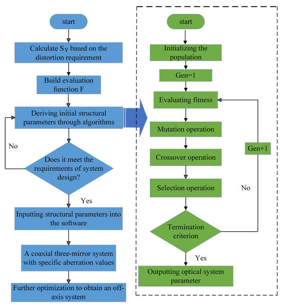
Figure 4.
Off-axis three-mirror system distortion control flowchart.
3. Design Example
In this section, two off-axis three-mirror systems were designed to validate the effectiveness of the aforementioned method. To establish an initial structure meeting the requirements, the mathematical model developed in Section 2 was employed. The objective function is defined as the minimization of the absolute difference between the weighted sum of the first four terms of Seidel aberrations and the predefined values of distortion, while assigning a weight of 2 to spherical aberration and coma, which have a significant impact on the imaging quality of the off-axis system, and a weight of 1 to the remaining aberrations. During the system design process, considerations for miniaturization and rationality of mirror structures necessitated constraints on the mirror spacing, curvature radii of the mirrors, and conic constants to ensure that the designed system meets practical application requirements. In algorithm design, the introduction of equality constraints restricts the degrees of freedom in the solution space, thereby reducing the solution space and increasing the difficulty of the optimization problem. Therefore, we constrained the focal length to a specified range.
Using the differential evolution algorithm to solve for the initial structure with specific distortion, the algorithm’s key parameters are set empirically as follows: initializing population size NP = 100, scaling factor F = 5 in mutation operation, crossover probability CR = 0.9, and maximum iteration count maxFE = 1000. The mathematical model is as follows:
Based on the constructed model, an off-axis three-mirror optical system with specific aberration values is designed, where the principal ray error ε = 180 μm. The detailed design specifications are outlined in Table 1.

Table 1.
Off-axis three-mirror optical system design parameters.
Based on the aforementioned error function, the differential evolution (DE) algorithm is utilized to search for the initial structural parameters that meet the requirements. Figure 5 depicts the variation in the error function with the number of iterations. Each blue marker on the curve represents the global optimal value of the error function at the specified iteration point. After 1000 iterations, the error function sharply decreases and then stabilizes, indicating convergence to a local minimum. Beyond 8000 iterations, it exits this local minimum, resulting in further reduction in the error function. By 10,000 iterations, the error function converges close to zero. This demonstrates the effectiveness of DE in navigating high-dimensional nonlinear optimization problems to find global optima.
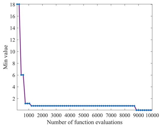
Figure 5.
Error function iteration curve.
Table 2 presents the initial structural parameters obtained through the differential evolution algorithm along with their corresponding distortion coefficient . The coefficients calculated align well with those provided in optical design software.

Table 2.
Off-axis three-mirror optical system initial parameters.
We selected the first configuration among the three initial setups because it exhibits lower spherical aberration and coma coefficients, making it easier to achieve good imaging quality off-axis. The initial configuration and distortion curve are depicted in Figure 6. The first surface corresponds to the object plane at infinity, the aperture stop is located on the primary mirror, which is the second surface, the third surface represents the secondary mirror, the fourth surface is the tertiary mirror, and the fifth surface corresponds to the image plane. The distortion curve illustrates that the maximum distortion at the edge of the field is 0.4524%.
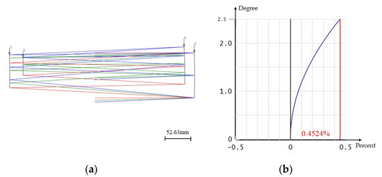
Figure 6.
(a) Initial configuration layout diagram; (b) F—tan θ distortion Diagram.
After obtaining a coaxial reflection system with specific distortion, it is imported into optical design software for further optimization. During the optimization process, eccentricity and tilt are often introduced to increase the degrees of freedom for correcting aberrations. Utilizing the built-in module JMRCC within the software, macro functions are scripted to calculate the distances between points and lines, which are then incorporated into the macro language as constraints to eliminate ray occlusion and overlap. Following optimization, the final system structural parameters are presented in Table 3, while the system’s two-dimensional layout and three-dimensional layout are illustrated in Figure 7.

Table 3.
Structural parameters of the off-axis triaxial optical system.
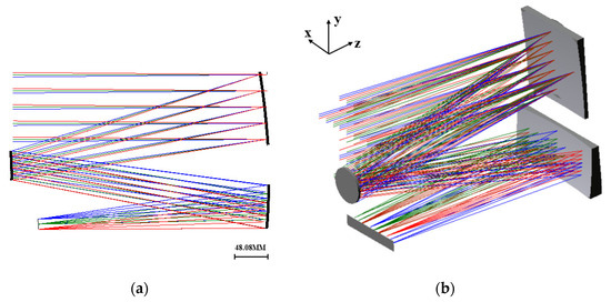
Figure 7.
(a) The optical system’s two-dimensional layout diagram; (b) The three-dimensional layout diagram of the optical system.
The modulation transfer function (MTF) is a crucial indicator for evaluating the imaging quality of optical systems. As shown in Figure 8, the MTF of the system is illustrated, and across the entire field of view, it exceeds 0.5 lp/mm, approaching the diffraction limit, indicating excellent imaging quality. The spot diagram effectively reflects the concentration of energy in the spot. The spot diagram for this system is depicted in Figure 9, wherein the black circles represent Airy discs, with a diameter of 6.45 μm calculated using the formula . The spot radius of all fields of view is smaller than that of the Airy disc.
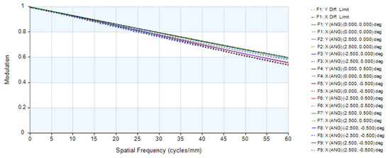
Figure 8.
The modulation transfer function (MTF) curves.
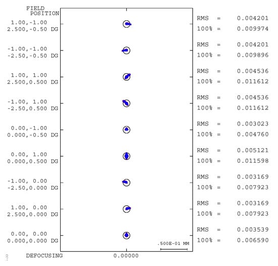
Figure 9.
System spot diagram.
The distortion grid can effectively characterize the deviation between ideal and actual imaging. The distortion grid for off-axis three-mirror optical systems is shown in Figure 10, where the red lines represent actual imaging, and the black lines represent ideal imaging. It can be observed from the figure that the two are essentially overlapping, indicating minimal distortion across the full field of view. The specific distortion magnitudes are shown in Table 4.
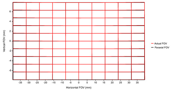
Figure 10.
System distortion grid.

Table 4.
Distortion magnitude across different fields of view.
“Rad Dist” represents radial distortion, including barrel distortion and pincushion distortion. During the optical system design phase, radial distortion can be utilized to compensate for the spectral line curvature generated by dispersive elements. As shown in Table 4, it can be seen that the distortion reaches a maximum value of 0.46% at the edge of the field of view, which is close to the initial structure’s 0.4524%. This indicates the effectiveness and reliability of the design method in controlling distortion.
Based on the aforementioned system, following the principle of “gradual progression”, we further expand the field of view and optimize to obtain a 10° × 1° off-axis three-mirror optical system. The optimized structural parameters of the system are presented in Table 5.

Table 5.
Off-axis three-mirror system structural parameters.
The two-dimensional layout of the system is illustrated in Figure 11, showing a compact system structure after further expanding the field of view. The modulation transfer function (MTF) is depicted in Figure 12, indicating that the image quality is good with values exceeding 0.5 across the entire field of view at 60 lp/mm.
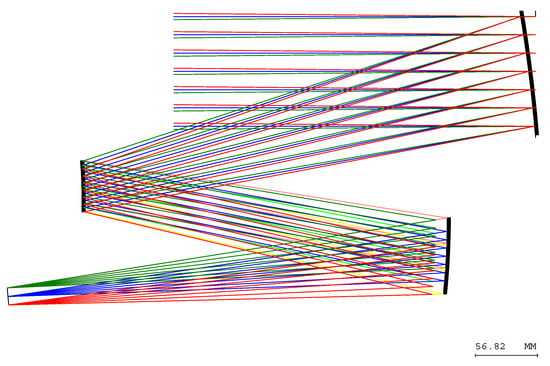
Figure 11.
The optical system’s two-dimensional layout diagram.
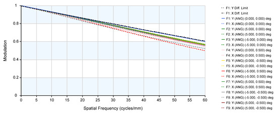
Figure 12.
The modulation transfer function (MTF) curves.
After further expanding the field of view, the system’s total field distortion is less than 0.76%, and there is no significant fluctuation in distortion between (−2.5°, −1°) and (2.5°, −1°), further indicating the effectiveness of this method in distortion control. The system’s grid distortion is illustrated in Figure 13.
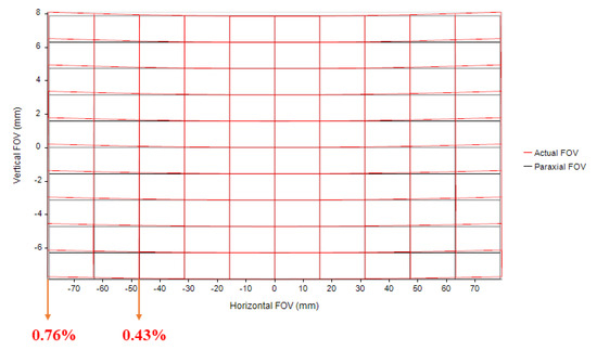
Figure 13.
System distortion grid.
4. Conclusions
During the optical system design phase, compensating for spectral line curvature caused by radial distortion generated by the front telecentric system and collimating objective is feasible. However, designing optical systems with specific distortion values presents challenges. This paper analyzes the tertiary aberration characteristics and derives the aberration formula for coaxial triple-mirror structures based on Seidel aberration theory, combined with ray tracing methods. The relationship between the distortion wavefront error and chief ray error is derived. This transforms the problem of solving for initial structural parameters with specific distortion values into an optimization problem of solving a nonlinear single-objective function, which is tackled using a differential evolution algorithm. The unique advantage of the differential evolution algorithm lies in its effectiveness in searching for global minimum values in high-dimensional, highly nonlinear parameter spaces, enabling efficient determination of initial structural parameters with specific distortion values. Taking a triple-mirror optical system as an example, optimization is performed based on a coaxial system with specific distortion values, significantly simplifying subsequent optimization processes and quickly obtaining an off-axis triple-mirror optical system that meets distortion requirements. The effectiveness and reliability of this method are verified, which is equally applicable to the design of off-axis two-mirror and multi-mirror systems.
Author Contributions
Conceptualization, E.L. and Y.Z.; methodology, E.L.; software, E.L.; validation, E.L., J.Z., C.L. and L.S.; formal analysis, E.L. and Y.N.; investigation, E.L.; resources, Y.Z.; data curation, E.L.; writing—original draft, E.L.; writing—review and editing, L.S.; visualization, C.L. and J.Z.; supervision, Y.Z.; project administration, Y.Z.; funding acquisition, Y.Z. All authors have read and agreed to the published version of the manuscript.
Funding
This research was funded by the National Key Research and Development Program of China (No. 2022YFB3904800, No. 2022YFB3904804), and the National Natural Science Foundation of China (No. 62334010).
Institutional Review Board Statement
Not applicable.
Informed Consent Statement
Not applicable.
Data Availability Statement
The original contributions presented in the study are included in the article, further inquiries can be directed to the corresponding author.
Conflicts of Interest
The authors declare no conflicts of interest.
References
- Liu, Y.; Bauer, A.; Viard, T.; Rolland, J.P. Freeform hyperspectral imager design in a CubeSat format. Opt. Express 2021, 29, 35915–35928. [Google Scholar] [CrossRef] [PubMed]
- Stuart, M.B.; McGonigle, A.J.S.; Willmott, J.R. Hyperspectral Imaging in Environmental Monitoring: A Review of Recent Developments and Technological Advances in Compact Field Deployable Systems. Sensors 2019, 19, 3071. [Google Scholar] [CrossRef] [PubMed]
- Meng, Q.; Wang, W.; Ma, H.; Dong, J. Easy-aligned off-axis three-mirror system with wide field of view using freeform surface based on integration of primary and tertiary mirror. Appl. Opt. 2014, 53, 3028–3034. [Google Scholar] [CrossRef] [PubMed]
- Qu, Z.; Zhong, X.; Zhang, K.; Wang, Y.; Li, L.; Liu, J.; Zeng, C. Automatic compact-volume design strategy for unobscured reflective optical systems based on conicoid surfaces. Opt. Commun. 2023, 533, 129304. [Google Scholar] [CrossRef]
- Sasian, J.; Reshidko, D. Method for the design of nonaxially symmetric optical systems using free-form surfaces. Opt. Eng. 2018, 57, 101704. [Google Scholar] [CrossRef]
- Shi, H.; Jiang, H.; Zhang, X.; Wang, C.; Liu, T. Analysis of nodal aberration properties in off-axis freeform system design. Appl. Opt. 2016, 55, 6782–6790. [Google Scholar] [CrossRef] [PubMed]
- Xu, C.; Lai, X.; Cheng, D.; Wang, Y.; Wu, K. Automatic optical path configuration variation in off-axis mirror system design. Opt. Express 2019, 27, 15251–15261. [Google Scholar] [CrossRef] [PubMed]
- Zhong, Y.; Gross, H. Initial system design method for non-rotationally symmetric systems based on Gaussian brackets and Nodal aberration theory. Opt. Express 2017, 25, 10016–10030. [Google Scholar] [CrossRef] [PubMed]
- Allain, G.; Thibault, S.; Johnson, R.B.; Mahajan, V.N.; Thibault, S. Distortion controlled optical design using orthogonal surface polynomials. In Proceedings of the Current Developments in Lens Design and Optical Engineering XXI, Online, 24 August–4 September 2020. [Google Scholar]
- Thomas, G.C.; Lacy, G.C. Design concept for a Landsat-class imaging spectrometer with well-corrected spectral fidelity. In Proceedings of the Optical Science and Technology, SPIE’s 48th Annual Meeting, San Diego, CA, USA, 3–8 August 2003; pp. 90–97. [Google Scholar]
- Meng, Q.; Wang, H.; Liang, W.; Yan, Z.; Wang, B. Design of off-axis three-mirror systems with ultrawide field of view based on an expansion process of surface freeform and field of view. Appl. Opt. 2019, 58, 609–615. [Google Scholar] [CrossRef] [PubMed]
- Cao, C.; Liao, S.; Liao, Z.; Bai, Y.; Fan, Z. Initial configuration design method for off-axis reflective optical systems using nodal aberration theory and genetic algorithm. Opt. Eng. 2019, 58, 105101. [Google Scholar] [CrossRef]
- Bakic, S.; Vasiljevic, D. Optimization of the double-Gauss objective with the various evolution strategies and the damped least squares. Phys. Scr. 2014, T162, 014034. [Google Scholar] [CrossRef]
- Cheng, X.; Wang, Y.; Hao, Q.; Isshiki, M. Global and local optimization for optical systems. Optik 2006, 117, 111–117. [Google Scholar] [CrossRef]
- Mouroulis, P.; Green, R.O.; Chrien, T.G. Design of pushbroom imaging spectrometers for optimum recovery of spectroscopic and spatial information. Appl. Opt. 2000, 39, 2210–2220. [Google Scholar] [CrossRef] [PubMed]
- Available online: http://www.opticalres.com (accessed on 21 April 2024).
- Lin, P.D. Seidel primary ray aberration coefficients for objects placed at finite and infinite distances. Opt. Express 2020, 28, 12740–12754. [Google Scholar] [CrossRef] [PubMed]
- Wang, J.; Guo, B.; Sun, Q.; Lu, Z. Third-order aberration fields of pupil decentered optical systems. Opt. Express 2012, 20, 11652–11658. [Google Scholar] [CrossRef] [PubMed]
- Bilal; Pant, M.; Zaheer, H.; Garcia-Hernandez, L.; Abraham, A. Differential Evolution: A review of more than two decades of research. Eng. Appl. Artif. Intell. 2020, 90, 103479. [Google Scholar] [CrossRef]
- Gui, L.; Xia, X.; Yu, F.; Wu, H.; Wu, R.; Wei, B.; Zhang, Y.; Li, X.; He, G. A multi-role based differential evolution. Swarm Evol. Comput. 2019, 50, 100508. [Google Scholar] [CrossRef]
Disclaimer/Publisher’s Note: The statements, opinions and data contained in all publications are solely those of the individual author(s) and contributor(s) and not of MDPI and/or the editor(s). MDPI and/or the editor(s) disclaim responsibility for any injury to people or property resulting from any ideas, methods, instructions or products referred to in the content. |
© 2024 by the authors. Licensee MDPI, Basel, Switzerland. This article is an open access article distributed under the terms and conditions of the Creative Commons Attribution (CC BY) license (https://creativecommons.org/licenses/by/4.0/).