Article

Temporal Analysis of Speckle Images in Full-Field Interferometric and Camera-Based Optical Dynamic Measurement

1
Guangdong Zhuhai Supervision Testing Institute of Quality and Metrology, Zhuhai 519000, China
2
College of Physics and Optoelectronic Engineering, Shenzhen University, Shenzhen 518060, China
*
Author to whom correspondence should be addressed.
Photonics 2024, 11(6), 548; https://doi.org/10.3390/photonics11060548
Submission received: 20 March 2024 / Revised: 1 June 2024 / Accepted: 7 June 2024 / Published: 8 June 2024
(This article belongs to the Special Issue Recent Advances in 3D Optical Measurement)

Abstract

:
Vibration measurement is crucial in fields like aviation, aerospace, and automotive engineering, which are trending towards larger, lighter, and more complex structures with increasingly complicated dynamics. Consequently, measuring a structure’s dynamic characteristics has gained heightened importance. Among non-contact approaches, those based on high-speed cameras combined with laser interferometry or computational imaging have gained widespread attention. These techniques yield sequences of images that form a three-dimensional space-time data set. Effectively processing these data is a prerequisite for accurately extracting dynamic deformation information. This paper presents two examples to illustrate the significant advantages of signal processing along the time axis in dynamic interferometric and digital speckle-image-based dynamic measurements. The results show that the temporal process effectively minimizes speckle and electronic noise in the spatial domain and dramatically increases measurement resolutions.

1. Introduction

Over the past several decades, the demand for high performance and reliability in industrial products has driven rapid development of high-precision measurement methods. Optical measurement, as a high-precision non-contact measurement method, developed significantly in the 1960s, especially after the invention of the laser. The emergence of a series of interferometric methods, such as holographic interference [1], speckle and shearing speckle [2], etc., has increased the resolution of the measurement of the amount of mechanical changes (deformations, displacements, etc.) to the order of the wavelengths of light, i.e., to the order of micrometers to sub-micrometers. At the end of the last century, with the development of the CCD camera and computer technology, a large number of digitized interferometry techniques emerged, such as electronic speckle pattern interferometry [3], digital shearing speckle interferometry [4], digital holography [5], and moiré interferometry [6]. Simultaneously, digital phase extraction techniques (e.g., skeletonization of fringes, temporal phase-shifting [7], and spatial phase-shifting [8] techniques) have enabled 2D interferometry to achieve a resolution of up to one-hundredth of the physical quantities represented by first-order interferometric fringes under optical laboratory conditions. In the case of out-of-plane displacements, for example, the measurement resolution is typically on the order of nanometers. In addition to interferometric techniques, non-interferometric techniques such as projected moiré [9], shadow moiré [10], fringe/speckle projections [11], and digital image correlation [12] have also developed significantly. Today’s optical measurements have covered the range of deformation measurements from the sub-nanometer to the macro scale. Image-based non-interferometric techniques [13,14] are limited by the diffraction limit of optical imaging, and the resolution of their deformation measurements can only reach the micrometer scale at the highest.
In their early stages of development, digitized laser interferometry and image measurement techniques measured static or quasi-static deformations, i.e., the amount of change between two states, mainly because of limitations in sensor acquisition speed [15]. Only laser Doppler vibrometry using single-pixel photodetector has achieved high-frequency/high-speed dynamic measurements of a single point or a limited number of points in the spatial domain [16], obtaining a one-dimensional amount of change in the displacement or velocity of the points along the time axis. At the beginning of this century, with the development of high-speed imaging acquisition technology, scientists combined high-speed cameras with various types of optical measurement methods so that a three-dimensional signal could be obtained [17], and optical dynamic measurements were gradually performed. At the same time, the phase extraction algorithms for one-dimensional, two-dimensional, and three-dimensional spatio-temporal interferometric signals [18], especially the Fourier transform [19], short-time Fourier transform [20], and wavelet transform [21], which are based on frequency-domain signal processing, have gained tremendous development. When static or quasi-static deformation is measured, removing speckle noise in interferometry and camera noise during the signal process is difficult. However, it has been found that temporal analysis is the most important in dynamic measurement to avoid speckle noise and increase measurement resolution, not only in speckle interferometry [22] but also in the digital image correlation technique [23,24].
This paper will examine two examples highlighting the advantages of temporal analysis for full-field vibration measurement-dynamic digital shearing speckle interferometry (DSSI) and laser Doppler vibrometer (LDV)-enhanced digital image correlation (DIC). The results demonstrate how processing sequences of noisy imaging data along the time domain enables much higher resolutions by mitigating noise sources like speckle and camera electronics noise that plague single-frame spatial analysis.

2. Temporal Analysis in Dynamic Digital Shearography

Shearography is a whole-field, non-contact optical technique that allows the direct measurement of first-order derivatives of deflection on spatial coordinates, depending on the measurement setup. The main advantage of shearography over other optical techniques is that its two interfering beams follow a closed optical path, so strict environmental stability during measurement is not required. In this application, we use digital shearography to measure stress-related parameters through phase retrieval when an object undergoes continuous deformation. A sequence of shearograms is captured by a high-speed camera during the deformation with a recording rate of 60 frame/s (fps) as shown in Figure 1. A temporal carrier is introduced to avoid the problem of phase ambiguity [25]. In shearography, when the image shearing in the y-direction is δ y , the phase change due to the deformation φ can be expressed as
φ = 2 π λ sin θ u y + sin β v y + 1 + cos θ w y δ y
where λ is the wavelength of the laser light. u, v, and w are the displacement components along the x, y, and z axes; θ and β are the illumination angles with respect to the yz-plane and the xz-plane, respectively. When these two angles are small enough, the phase change φ is mainly contributed by w y .
Image subtraction is then performed using digital shearography, and the result can be expressed by the following equation.
I = 2 I A sin ϕ + φ 2 sin φ 2
Equation (2) comprises a high-frequency varying term modulated by a low-frequency varying term, and fringes are visible in a random speckle background. Figure 2a shows a typical shearographic fringe pattern on a circular plate with central-point loading. Generally, phase-shifting is the most popular technique applied in digital shearography to extract the phase variation. However, it requires at least three images captured with prescribed phase steps at one static status; subsequently, it is not easily accomplished [6] when measuring an object undergoing continuous deformation.
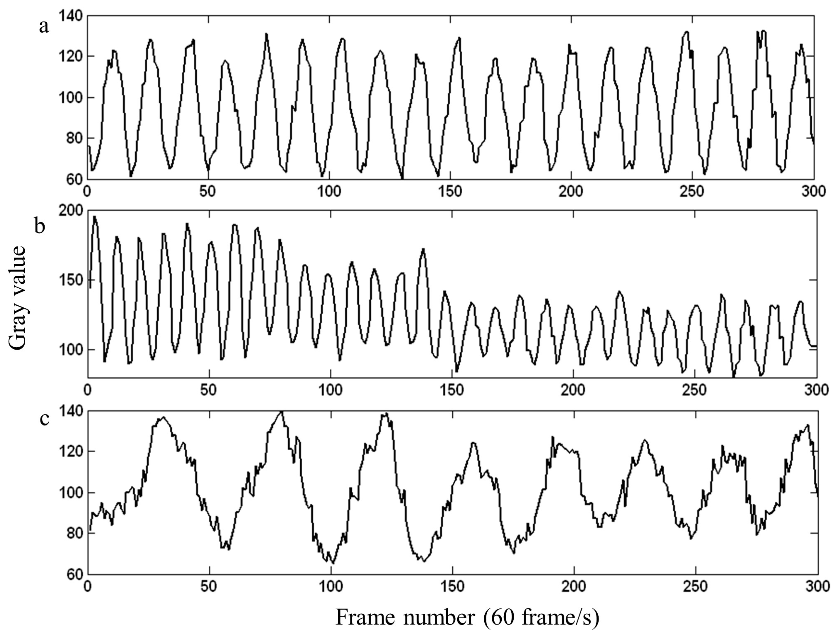
In this study, three hundred speckle patterns were selected for pixel-by-pixel processing along the time axis. For each pixel, 300 sampling points were obtained along the time axis. Figure 3 shows the intensity variation over time of point R (indicated in Figure 1) on the reference block, as well as the intensity variation of points A and B (as shown in Figure 1), respectively. When the shearing occurs in the y-direction and under near normal illumination and viewing conditions, the intensity variation of each pixel can be expressed as
I x y ( t ) = I 0 x y ( t ) + A x y ( t ) cos [ φ x y ( t ) ] = I 0 x y ( t ) + A x y ( t ) cos [ ϕ C ( t ) + ϕ x y ( t ) ] = I 0 x y t 1 + V cos φ 0 x y + 2 π f C t + 4 π w x y t y δ y λ
where I 0 x y ( t ) is the intensity bias of the speckle pattern, V is the visibility, φ 0 x y is the initial random phase, f C is the temporal carrier frequency, φ C ( t ) = 2 π f C t is the phase change due to the temporal carrier, δ y is the amount of image shearing in the y-direction, and w x y ( t ) is the out-of-plane deformation of the object. At each pixel, the temporal intensity variation is analyzed by one-dimensional temporal Fourier analysis. Figure 2b shows the wrapped phase after temporal analysis, while Figure 2c shows the unwrapped phase map.

3. Temporal Analysis in Dynamic Digital Image Correlation

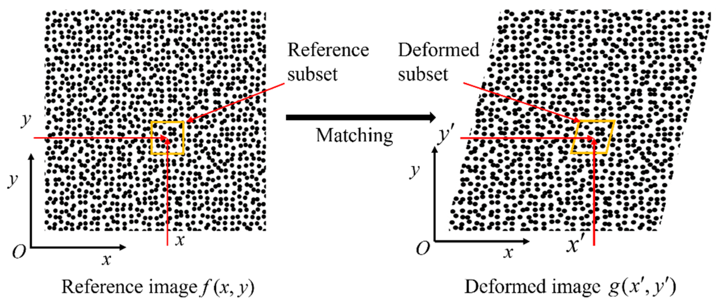
Digital image correlation (DIC) stands as a robust and adaptable optical technique employed for the assessment of displacement, deformation, and strain of structures. Its application spans various fields, including materials science, mechanical engineering, and structural evaluation. In DIC, a random, high-contrast speckle pattern is applied to the object’s surface under study. This pattern is crucial as it provides unique features that can be tracked across the images. Images are captured before and after deformation using a digital camera. The resolution of the camera and the quality of the images directly affect the accuracy and resolution of the measurement. The algorithm of DIC is the correlation process. It involves dividing the reference image (before deformation) into small subsets or windows. Each subset contains a unique part of the speckle pattern. For each subset in the reference image (Figure 4), the DIC algorithm searches for the corresponding subset in the deformed image (after deformation). This search is guided by a Zero Normalized Sum of Squared Differences (ZNSSD) Criterion to find the best match. Once the corresponding subsets are identified, the displacement of each subset from its original position can be calculated.
One of the strengths of DIC is its ability to achieve sub-pixel accuracy in displacement measurements. By using interpolation techniques and robust correlation algorithms, DIC can measure displacements that are a fraction of a pixel size. In order to measure the out-of-plane displacement of a vibrating object, a sequence of images are captured by binocular vision system (as shown in Figure 5). DIC must match not only the images before and after deformation, but also images from different cameras comprising stereo vision. Stereo matching combined with pre-calibrated imaging intrinsic parameters and position relationships between the cameras enables 3D reconstruction of the target. Three-dimensional deformation for the surface to be measured can be calculated after obtaining three-dimensional coordinates for the points before and after deformation. In this application, only out-of-plane vibrations are concerned.
In this study, 3D-DIC and LDV are synchronized to measure the out-of-plane displacement of a vibrating object, as shown in Figure 6. The different orders of vibration mode shapes are excited by a shaker (V201, B&K, UK) together with a waveform generator (SDG6052X, SIGLENT, China). A single-point LDV (FNV-R1D-VD1, Holobright, Singapore) measures the vibration at one point and calculates the vibration phase in real time. At different phase angles, two LED lights and two low-speed cameras (UI-3370CP-M-GL Rev.2, IDS, Germany) are triggered to capture a complete cycle of vibration. Figure 6a shows the frequency spectrum of DIC measurement results, where noise frequencies and the signal frequency are aliased. These noise components make the waveform measured by DIC unidentifiable, as depicted by the black line in Figure 6c. Figure 6b shows the frequency spectrum measured by an LDV. In vibration signal processing, temporal analysis of DIC signal processing was guided by LDV spectrum. A bandpass filter is applied to remove the noise. Its central frequency is determined by the peak value of the LDV spectrum. Figure 6c presents the time domain waveform of the processed DIC signal (Figure 6c blue line) and LDV signal (Figure 6c red line). These waveforms are synchronized in both amplitude and phase. As shown in the comparison in Figure 6c, the maximum error is approximately 5% if we consider the result from the LDV as the true value. The method was initially implemented on a single pixel along the time axis and then extended to the whole image in the DIC measurement results. Figure 7a shows the eighth-order modal obtained by DIC. The DIC measurement results are significantly disturbed by noise. Subsequently, the LDV assists DIC in removing the noise frequencies from all pixels. Figure 7b shows the vibration mode obtained through LDV-enhanced DIC.

4. Discussion

From the two measurement results shown above, one commonality in dynamic measurement can be observed. In speckle interferometry techniques like digital shearing shearography, it is very difficult to obtain a good-quality phase map from the standard spatial processing of a single interferogram, especially when the fringe density is high and the fringe spatial frequencies are similar to the speckle noise frequencies. The speckle noise overlaid on the interference fringes acts to corrupt and obscure the actual fringe pattern representing the object deformation. On the other hand, pixel-wise temporal analysis processing the full sequence of interferograms is able to effectively separate the time-varying deformation signal from the time-invariant speckle noise. By analyzing how each pixel fluctuates over time, rather than its single value, the underlying deformation can be distinguished from the stochastic speckle pattern. This allows the generation of much higher-quality deformation phase maps compared to the spatial processing of single interferograms.
Similarly, in dynamic imaging techniques like digital image correlation (DIC), measurement errors can arise from many sources including poor speckle pattern quality, fluctuations in illumination, camera sensor noise, camera electronics noise, and limitations of the correlation algorithm itself. Among these error sources, camera noise often constitutes the largest source of error, especially for high-speed imaging required for dynamic measurements. Camera sensor noise arises from thermal effects in the sensor pixels, which increases for longer exposures and higher sensor temperature settings. Read noise from the camera’s electronics also contributes noise to the image data. This camera noise contaminates all pixels in each image frame, appearing as random high-frequency fluctuations overlaid on the actual spatial intensity patterns that encode the object deformation.
Attempting to measure deformation from a single pair of noisy images using standard 2D spatial correlation is difficult. Random noise, including varying environmental conditions (such as temperature fluctuations and humidity), makes it difficult to accurately match local subsets of the speckle patterns between the reference and deformed images, leading to corruption of the measured displacement and strain maps. However, by processing the full sequence of image frames using temporal analysis techniques, the time-invariant noise can be separated from the time-varying actual deformation signal, in much the same way that temporal analysis enables the separation of speckle noise in interferometry. Analyzing how the intensity of each pixel varies over time allows the underlying dynamics to be reliably extracted despite the presence of noise in each individual frame.
The examples of digital shearography and DIC clearly illustrate the significant advantages of temporal analysis over spatial analysis for dynamic measurements from sequences of noisy imaging data. By working in the time domain rather than the spatial domain, many of the noise sources that plague single-frame measurements can be mitigated, enabling higher resolution and higher accuracy measurements of structural dynamics and deformations.
Beyond just these two examples, the principles of temporal analysis are widely applicable to many other dynamic imaging techniques, such as digital holography, moiré interferometry, and fringe projection, etc., in fields such as biomechanics, fluid dynamics, and general time-resolved imaging. As high-speed camera technology continues to advance, providing higher resolution and faster frame rates, temporal analysis methods will become increasingly important tools for processing the large 3D space-time data sets generated by these cameras.
Future research directions may focus on developing new temporal analysis algorithms tailored for specific imaging modalities, investigating techniques for real-time implementation of temporal analysis, and exploring ways to optimally combine spatial and temporal processing to leverage the advantages of both domains. Additionally, emerging areas like machine learning and compressed sensing could potentially provide new analytical avenues to extract even more information from dynamic imaging data sets.

5. Conclusions

This study has shown the advantages of temporal analysis in optical dynamic measurement. In high-speed camera-based digital speckle shearing interferometry, processing the sequence of interferograms pixel-by-pixel along the time axis can avoid the effects of speckle noise in the spatial domain. In LDV-guided digital image correlation for vibration measurement, temporal processing of the out-of-plane displacement obtained by DIC can significantly remove camera noise and dramatically increase measurement resolution. The results show that temporal analysis is a useful tool in optical dynamic measurement, especially in processing speckle images.

Author Contributions

Investigation, G.B. and Y.W.; Writing—original draft, B.C. and Y.F.; Supervision, B.C. All authors have read and agreed to the published version of the manuscript.

Funding

This research received no external funding.

Institutional Review Board Statement

Not applicable.

Informed Consent Statement

Not applicable.

Data Availability Statement

Data are contained within the article.

Conflicts of Interest

The authors declare no conflicts of interest.

References

  1. Vest, C.M. Holographic Interferometry; John Wiley & Sons: New York, NY, USA, 1979. [Google Scholar]
  2. Hung, Y.Y. Shearography: A new optical method for strain measurement and nondestructive testing. Opt. Eng. 1982, 21, 213391. [Google Scholar] [CrossRef]
  3. Partovi Shabestari, N.; Rashidian Vaziri, M.R.; Bakhshandeh, M.; Alidokht, I.; Alizadeh, Y. Fabrication of a simple and easy-to-make piezoelectric actuator and its use as phase shifter in digital speckle pattern interferometry. J. Opt. 2019, 48, 272–282. [Google Scholar] [CrossRef]
  4. Hung, Y.Y.; Shang, H.M.; Yang, L. Unified approach for holography and shearography in surface deformation measurement and nondestructive testing. Opt. Eng. 2003, 42, 1197–1207. [Google Scholar] [CrossRef]
  5. Huang, H.; Yuan, E.; Zhang, D.; Sun, D.; Yang, M.; Zheng, Z.; Zhang, Z.; Gao, L.; Panezai, S.; Qiu, K. Free Field of View Infrared Digital Holography for Mineral Crystallization. Cryst. Growth Des. 2023, 23, 7992–8008. [Google Scholar] [CrossRef]
  6. Post, D.; Han, B.; Ifju, P. High Sensitivity Moiré: Experimental Analysis for Mechanics and Materials; Springer Science & Business Media: Berlin, Germany, 2012. [Google Scholar]
  7. Yamaguchi, I.; Zhang, T. Phase-shifting digital holography. Opt. Lett. 1997, 22, 1268–1270. [Google Scholar] [CrossRef] [PubMed]
  8. Shan, M.; Hao, B.; Zhong, Z.; Diao, M.; Zhang, Y. Parallel two-step spatial carrier phase-shifting common-path interferometer with a Ronchi grating outside the Fourier plane. Opt. Express 2013, 21, 2126–2132. [Google Scholar] [CrossRef] [PubMed]
  9. Tang, Y.; Yao, J.; Zhou, Y.; Sun, C.; Yang, P.; Miao, H.; Chen, J. Calibration of an arbitrarily arranged projection moiré system for 3D shape measurement. Opt. Lasers Eng. 2018, 104, 135–140. [Google Scholar] [CrossRef]
  10. Seif, M.A.; Khashaba, U.A.; Rojas-Oviedo, R. Measuring delamination in carbon/epoxy composites using a shadow moiré laser based imaging technique. Compos. Struct. 2007, 79, 113–118. [Google Scholar] [CrossRef]
  11. Zhang, S. Recent progresses on real-time 3D shape measurement using digital fringe projection techniques. Opt. Lasers Eng. 2010, 48, 149–158. [Google Scholar] [CrossRef]
  12. Sutton, M.A.; Orteu, J.-J.; Schreier, H.W. Image Correlation for Shape, Motion and Deformation Measurements; Springer: Boston, MA, USA, 2009; ISBN 978-0-387-78746-6. [Google Scholar]
  13. Tay, C.; Quan, C.; Huang, Y.; Fu, Y. Digital image correlation for whole field out-of-plane displacement measurement using a single camera. Opt. Commun. 2005, 251, 23–36. [Google Scholar] [CrossRef]
  14. Wu, Z.; Guo, W.; Zhang, Q. High-speed three-dimensional shape measurement based on shifting Gray-code light. Optis Express 2019, 27, 22631–22844. [Google Scholar] [CrossRef] [PubMed]
  15. Pedrini, G.; Osten, W.; Gusev, M.E. High-speed digital holographic interferometry for vibration measurement. Appl. Opt. 2006, 45, 3456–3462. [Google Scholar] [CrossRef] [PubMed]
  16. Yang, C.; Guo, M.; Liu, H.; Yan, K.; Xu, Y.J.; Miao, H.; Fu, Y. A multi-point laser Doppler vibrometer with fiber-based configuration. Rev. Sci. Instrum. 2013, 84, 121702. [Google Scholar] [CrossRef] [PubMed]
  17. Chen, F.; Luo, W.D.; Dale, M.; Petniunas, A. High-speed ESPI and related techniques: Overview and its application in the automotive industry. Opitcs Lasers Eng. 2003, 40, 459–485. [Google Scholar] [CrossRef]
  18. Qian, K.; Fu, Y.; Liu, Q.; Seah, H.S.; Asundi, A. Generalized three-dimensional windowed Fourier transform for fringe analysis. Opt. Lett. 2006, 31, 2121–2123. [Google Scholar] [CrossRef] [PubMed]
  19. Joenathan, C.; Franze, B.; Haible, P.; Tiziani, H.J. Large in-plane displacement measurement in dual-beam speckle interferometry using temporal phase measurement. J. Mod. Opt. 1998, 45, 1975–1984. [Google Scholar] [CrossRef]
  20. Kemao, Q. Applications of windowed Fourier fringe analysis in optical measurement: A review. Opt. Lasers Eng. 2015, 66, 67–73. [Google Scholar] [CrossRef]
  21. Goudemand, N. Application of dynamic phase shifting wavelet analysis to electronic speckle contouring. Appl. Opt. 2006, 25, 3704–3711. [Google Scholar] [CrossRef] [PubMed]
  22. Shiraishi, T.; Toyooca, S.; Kadono, H.; Saito, T. Dynamic ESPI system for spatio-temporal strain analysis of a deforming solid object. Key Eng. Mater. 2006, 326–328, 95–98. [Google Scholar] [CrossRef]
  23. Pan, B. Bias error reduction of digital image correlation using Gaussian pre-filtering. Opt. Lasers Eng. 2013, 51, 1161–1167. [Google Scholar] [CrossRef]
  24. Gao, Z.; Xu, X.; Su, Y.; Zhang, Q. Experimental analysis of image noise and interpolation bias in digital image correlation. Opt. Lasers Eng. 2016, 81, 46–53. [Google Scholar] [CrossRef]
  25. Fu, Y.; Guo, M.; Liu, H. Determination of instantaneous curvature and twist by digital shearography. Opt. Eng. 2012, 51, 083602. [Google Scholar] [CrossRef]
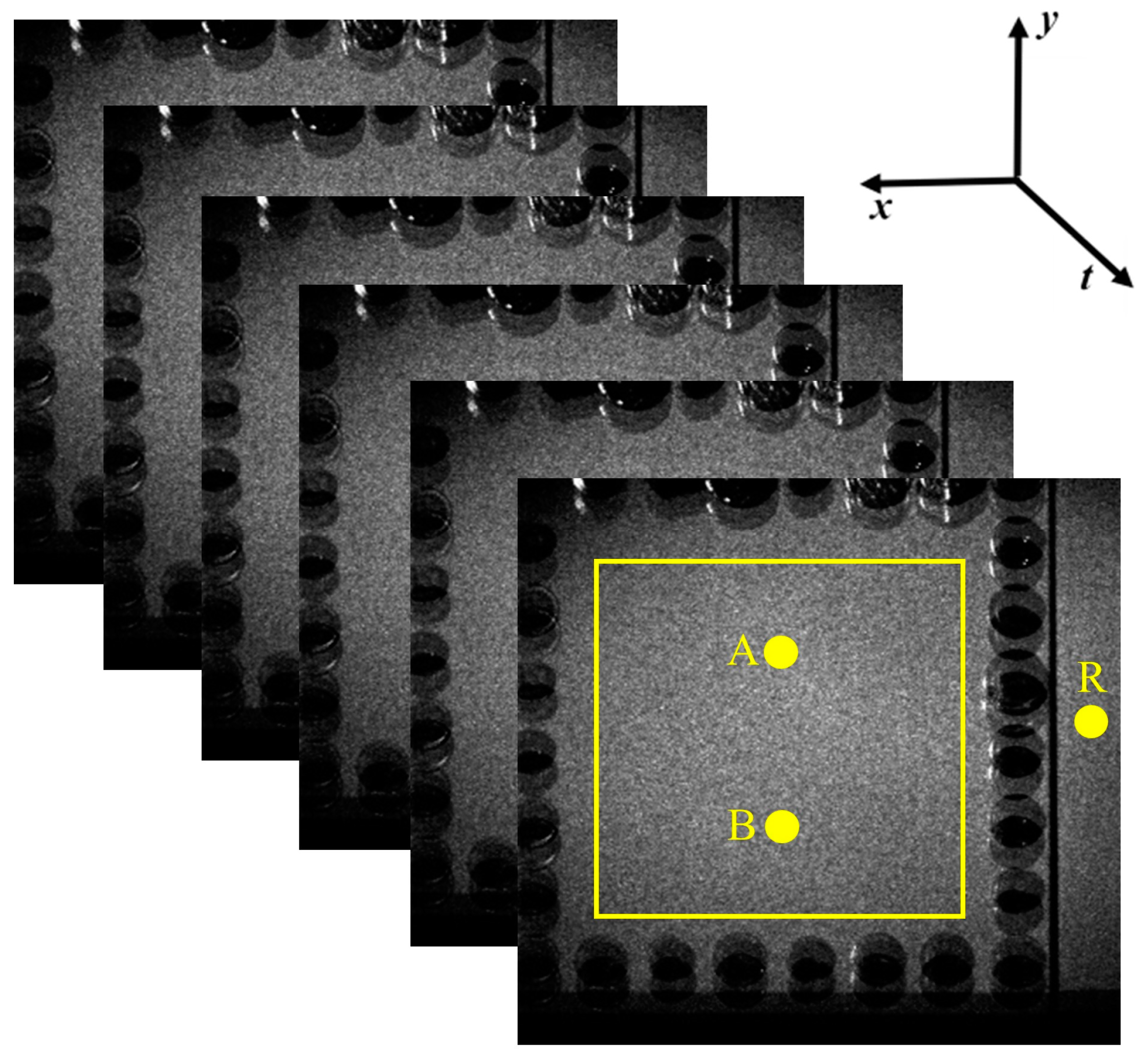
Figure 1. A sequence of speckle patterns obtained by a shearography setup.
Photonics 11 00548 g001
Figure 2. (a) Typical shearographic fringe pattern; (b) instantaneous wrapped phase obtained by temporal Fourier analysis and (c) instantaneous continuous phase after unwrapping.
Photonics 11 00548 g002
Figure 3. Temporal intensity variations of (a) point R on the reference block and of (b) point A and (c) point B on the square plate.
Photonics 11 00548 g003
Figure 4. Principle of digital image correlation. The yellow boxes are the subset in the reference and deformed image.
Photonics 11 00548 g004
Figure 5. (a) Experimental setup of LDV-guided 3D-DIC for vibration measurement; (b) a vibrating plate with one fixed side.
Photonics 11 00548 g005
Figure 6. (a) Typical vibrating spectrum of one pixel; (b) typical vibration spectrum obtained by LDV; and (c) typical vibration displacement of one pixel from DIC, LDV, and LDV−guided DIC.
Photonics 11 00548 g006
Figure 7. (a) The 8th order of vibration mode obtained by DIC only; (b) the same vibration mode obtained by LDV−guided DIC.
Photonics 11 00548 g007
Disclaimer/Publisher’s Note: The statements, opinions and data contained in all publications are solely those of the individual author(s) and contributor(s) and not of MDPI and/or the editor(s). MDPI and/or the editor(s) disclaim responsibility for any injury to people or property resulting from any ideas, methods, instructions or products referred to in the content.