Abstract
Single-shot dual-wavelength interferometry offers a promising avenue for surface profile measurement of dynamic objects. However, current techniques employing pixel multiplexing or color cameras encounter challenges such as complex optical alignment, limited measurement range, and difficulty in measuring rough surfaces. To address these issues, this study presents a novel approach to single-shot dual-wavelength interferometry. By utilizing separated polarization illumination and detection, along with a monochromatic polarization camera and two slightly different wavelengths, this method enables the simultaneous recording of two frames of separated interferometric patterns. This approach facilitates straightforward optical alignment, expands measurement ranges, accelerates data acquisition, and simplifies data processing for dual-wavelength interferometry. Consequently, it enables online shape measurement of large dynamic samples with rough surfaces.
1. Introduction
Surface profile measurement is pivotal for assessing the quality of various materials, including metals, plastics, and glass components, with significant implications for both industrial applications and scientific research [1]. A key player in this domain is interferometry, a robust and widely utilized technique renowned for its role in precisely measuring the surface profile of optical elements [2]. This technique involves the interference of the image, , of the object under inspection with a planar reference light beam, , resulting in interference fringes described as . The wavelength of the illumination beam and the surface profile of the object are crucial to this pattern and can be described as . Spatial filtering [3] or phase shifting methods [4,5] are commonly used to accurately compute the surface profile from the interference pattern . This is a fundamental and well-known principle of interferometry. Interferometry-based methods offer notable advantages over alternatives like spectral confocal [6,7] and structured illumination [8,9] methods, providing superior accuracy, speed, and a large field of view [10]. For instance, interferometry excels in measuring objects with diameters larger than 500 mm, achieving accuracy in the nanometer range at video rate [10]. Interferometry-based methods offer notable advantages in terms of high precision, rapid data acquisition, and a broad field of view compared to alternative methodologies. However, single-wavelength interferometry is constrained by the nanometer wavelength of the laser source, limiting its ability to measure very small surface profiles of objects and restricting its application range.
Subsequently, researchers proposed a dual-wavelength method [11,12,13] to enhance the measurement range of object surface profiles. The principle involves using lasers with wavelengths and to illuminate the object separately, capturing two frames of interferograms. According to specific objectives, research in dual-wavelength interferometry can be categorized into two main groups. One group focuses on enhancing the accuracy of phase unwrapping by processing two interferograms of different wavelengths separately [14,15,16]. The other group aims to achieve a large, synthesized wavelength, to measure the shape of large objects through methods such as multiplication or subtraction of interferograms with slightly different wavelengths [17]. In the latter group of dual-wavelength interferometry, the phase of the synthesized interference fringe can be calculated as , where represents the height of the surface profile of the object under measurement. Given that the synthetic wavelength is significantly larger than both and , the measurement range of dual-wavelength interferometry far exceeds that of single-wavelength interferometry. Even objects with heights of several centimeters can be accurately measured using two visible wavelengths. In typical dual-wavelength interferometry, at least two frames of interferograms need to be recorded while two laser sources with slightly different wavelengths, and , are sequentially switched on and off. The minimum data acquisition time is typically several milliseconds. Thus, conventional dual-wavelength interferometry, while offering expanded measurement ranges, has been limited by relatively lengthy data acquisition times, hindering its applicability to dynamic objects. Consequently, this method may not be suitable for measuring the surfaces of dynamic objects in many cases. To overcome this limitation, various approaches to single-shot dual-wavelength interferometry have been developed, including those employing pixel multiplexing schemes [18,19,20] or color cameras [21,22]. In pixel multiplexing-based dual-wavelength interferometry, the interferograms exhibit interference fringes with different orientations or periods, enabling their separation in the Fourier domain for subsequent individual processing. However, achieving this separation requires intricate optical alignment, often involving the use of diffraction gratings or quarter-wave plates. Moreover, the presence of multiple diffraction orders in the Fourier transform of the recorded image adds complexity to the data processing in pixel multiplexing-based dual-wavelength interferometry. Furthermore, this single-shot method is unsuitable for measuring objects with rough surfaces, as visible fringes are absent in both interferograms of different wavelengths. On the other hand, color camera-based dual-wavelength interferometry utilizes RGB pixels to capture red, green, and blue images separately, with a micro polarizer array employed for polarization phase shifting. This approach typically entails simpler optical alignment and data processing. However, due to the significant wavelength intervals among red, green, and blue lasers, the synthesized wavelength is limited. Consequently, this method is unable to effectively measure large objects [23,24].
To extend the application of single-shot dual-wavelength interferometry to the measurement of large objects with rough surfaces, such as common plastic, metal, or glass components, this paper proposes a novel approach. Utilizing a monochromatic polarization camera, the method directly acquires two separate interferograms of slightly different wavelengths, enabling single-shot dual-interferometry with a broad measurement range, simplified optical alignment, convenient data acquisition, and straightforward data processing. By precisely aligning the polarizations of the illuminations at and along the x-axis and y-axis, respectively, two interferograms of and can be directly recorded by pixels equipped with polarizers in the x-axis and y-axis orientations. Eliminating the need for pixel multiplexing and employing slightly different wavelengths, this proposed method achieves simultaneous simplicity in optical alignment and expansiveness in the measurement range. Additionally, the overall data acquisition time, primarily governed by detector exposure, is effectively reduced to mere microseconds in many scenarios. Furthermore, since the two recorded interferograms can be processed independently, the data processing of this proposed method remains straightforward. Consequently, our approach facilitates the seamless measurement of large dynamic objects with very rough surfaces, previously challenging to measure with interferometry-based techniques.
Although polarization techniques have been demonstrated in both multi-wavelength techniques (MWT) and dual-wavelength interferometry to expedite data acquisition [25], primarily for phase shifting or crosstalk reduction between wavelengths during their propagation to the camera, our method represents the first instance, to our knowledge, of achieving rapid dual-wavelength interferometry using polarization illumination and polarization detection in conjunction with a monochromatic polarization camera. This integration enables the simultaneous simplification of optical alignment, expansion of measurement range, acceleration of data acquisition, and streamlining of data processing.
2. Principle of Common Dual-Wavelength Interferometry
The surface of any real object can be expressed as , wherein denotes the surface profile, and signifies the surface roughness. In numerous instances, assumes the form of a rapidly fluctuating, stochastic function of coordinates , with our primary focus directed towards its static attributes [26]. By expanding the interference term as we gain insightful perspectives into the influence of the scale of in relation to the wavelength [27].
In the case of optical elements where is at a scale significantly smaller than the illumination wavelength, the terms and approximate zero and 1.0, respectively. Consequently, the interferometry simplifies to , facilitating the accurate computation of from . However, for common metal and plastic components featuring much larger than , interference fringes become irregular as both and randomly and abruptly change from −1 to +1 with coordinates , and the surface profile cannot be computed from This limitation forms the basis for the constraint of interferometry to optical elements. Theoretically, using radiation with a wavelength of 10 um or larger could make very small for most metal or plastic objects. However, practical limitations, such as the lack of high-resolution 2D detectors for wavelengths larger than 10 um, hinder interferometry’s ability to measure rough object shapes. To realize the surface profile measurement on an object with considerable height or large roughness, dual-wavelength interferometry was developed [28], where two laser beams with slightly different wavelengths, and , were applied to capture two interferograms, and , and interference fringes at a quite long synthetic wavelength, , can be obtained by directly subtracting or multiplying these two interferograms.
When laser beam , with a wavelength of , vertically illuminates an object, the reflected light takes the form . Interfering this reflected light with a plane wave of results in the formation of an interferogram,
Since both and can be separately recorded, subtracting them from yields
Changing the illumination wavelength from to produces another equation,
By multiplying Equation (3) and Equation (2),
For common plastic and metal objects, which always have quite rough surfaces, is considerably larger than both and and is a rapid and random function of the coordinates ; the first term on the right side of Equation (4) exhibits high-frequency noise, easily removable with spatial filtering. Since is significantly smaller than both and , particularly when and are closely aligned, the second term on the right side of Equation (4) manifests as a gradual function of the coordinates . Thus, the second term and the first term can be effectively separated in the Fourier domain. Utilizing phase-shifting or spatial modulation methods enables the computation of the phase of the second term, , and, consequently, the extraction of the rough surface . Since typically varies rapidly with coordinates and may be unresolved for camera pixels of finite size, the computed result essentially represents the surface profile .
3. Single-Shot Dual-Wavelength Interferometry with a Polarization Camera
The operational principle of single-shot dual-wavelength interferometry, employing a polarization camera, is shown in Figure 1. In this set up, laser beams at and are polarized along the x-axis and y-axis, respectively, and subsequently combined via a polarized beam splitter (PBS). The merged laser beam undergoes expansion and collimation before entering the interferometer equipped with a spatial filter (SF) and collimating lens (L1). Within the interferometer, the incident laser beam splits into two paths: one illuminates the sample (S), while the other reflects off a slightly tilted reference mirror (M). The resulting reflected light beams from both the object and the reference mirror interfere with the sensitive chip of a polarization CCD camera. The inset illustrates the structure of the CCD’s sensitive chip, where pixels containing horizontal and vertical patterns record light polarized along the x and y directions, respectively. Additionally, pixels filled with patterns oriented from up–left to down–right detect light polarized at an angle of −45° relative to the y-axis, while those with patterns from up–right to down–left receive light polarized at an angle of +45° relative to the y-axis. The CCD camera is positioned on the common imaging plane of both mirror M and sample S. By detecting light polarized in four different directions using corresponding pixels of the polarized camera, the experimental setup depicted in Figure 1 is significantly simpler and more compact compared to a previously reported approach [29] that employs a pixel multiplexing scheme.
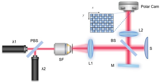
Figure 1.
Principle of single-shot dual-wavelength interferometry with a polarization camera. PBS, polarization beam splitter; SF, spatial filter; L1, lens; M, mirror; S, sample.
Upon arriving at mirror M, laser beams of wavelengths λ₁ and λ₂ are initially polarized along the x-axis and y-axis, respectively. Upon reflection from M, their polarization remains unchanged as they reach the detector, denoted as R(λ₁) and R(λ₂), respectively. However, when these beams interact with the rough surface of sample S, their polarization becomes degraded. Some of the light with wavelength λ₁ becomes polarized in the y-direction, while some of the light with wavelength λ₂ becomes polarized in the x-direction. The light with wavelength λ₁ reflected from S is represented by two polarization components, and , corresponding to the x-direction and y-direction, respectively. Similarly, the light with wavelength λ₂ reflected from S is represented by and for the x-direction and y-direction, respectively. The intensity formed by light polarized in the x-direction and that formed by light polarized in the y-direction can be expressed as follows:
The intensities and can be captured by pixels configured with horizontal and vertical patterns, respectively, as illustrated in Figure 1.
To measure these intensities, one can alternately switch on/off the laser sources emitting light of wavelengths λ₁ and λ₂ and selectively block the reference and object arms of the interferometer. This allows for the separate recording of , , , , , and . With these measurements in hand, Equations (5) and (6) can be rewritten as follows:
By multiplying Equation (7) with Equation (8),
Equation (9) can be simplified to
This equation follows the same principle of common dual-wavelength interferometry as discussed in Equation (4). By analyzing the interference terms , the rough surface profile can be extracted effectively using Equation (10). As varies rapidly with coordinates (x,y) and cannot be resolved by camera pixels with finite size, the computed result essentially represents the surface profile . Moreover, as the interference fringe of each individual wavelength is not accessible for surfaces with roughness, all computations are conducted using the synthesized wavelength. Hence, the accuracy of this proposed method primarily relies on the accuracy of .
Furthermore, since Equation (10) is derived from interferograms of two polarization components and data acquisition is completed with a single camera exposure, the data acquisition speed is primarily determined by the speed of the CCD camera. For most commercially available industrial cameras, this speed can be reduced to several microseconds, making dual-wavelength interferometry sufficiently fast for measuring dynamic surfaces.
However, it cannot be guaranteed that the intensities of , , , remain exactly unchanged throughout the entire experiment, especially when considering dynamic samples and unstable laser sources. Consequently, two additional terms indicating their changes are introduced and denoted as and These terms then appear on the right sides of Equation (7) and Equation (8), respectively. Subsequently, when Equation (7) is multiplied to Equation (8), three additional terms emerge on the right side of Equation (10): , , and . However, given their random speckle distribution and relatively small values, these three terms, along with the first term of Equation (10), can be effectively filtered out using spatial filtering techniques.
4. Proof of Principle Experiments
To validate the feasibility of the proposed measurements, a series of principle verification experiments were conducted using two illumination wavelengths: = 632.8 nm and = 637.3 nm. The experimental setup, depicted in Figure 2a, involved merging two polarized laser beams via PBS and then through a collimating and expanding system. This system comprised a spatial filter (SF) and a collimating lens. The SF, consisting of a microscopic objective lens and a pinhole, served to expand and filter the laser beam. The microscopic objective lens transformed the thin laser beam into a spherical wave at the pinhole to mitigate high-frequency noise induced by dust or lens imperfections. Subsequently, the beam was converted into parallel light upon traversing the SF and then the collimating lens (L1). The interference system adopted a Twyman–Green interferometer structure to generate interferograms. In the interferometer, the object under measurement and a plane mirror acting as the reference object were positioned in separate arms.
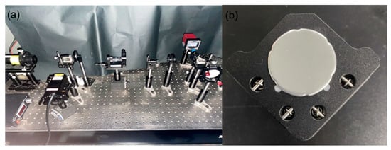
Figure 2.
(a) The optical alignment. (b) Close-up view of the sample (a painted plastic sheet fixed to the lens holder).
The specimen utilized in these experiments, depicted in Figure 2b, consisted of a round painted plastic sheet affixed to a lens holder along its side. Positioned at the center of the lens holder was a spiral micrometer, enabling the alteration of the plastic sheet’s shape by introducing various deformations. Precise adjustments to the spiral micrometer allowed for accurate manipulation of the thin sheet’s deformation, with the maximum deformation directly determinable by reading the measuring scale on the micrometer.
Due to the paint coating on the plastic sheet, its surface lacked optical smoothness, resulting in a roughness exceeding the wavelengths = 632.8 nm and nm. Consequently, conventional interferometry methods proved inadequate for characterizing such surface features. To address this challenge, we activated the laser with a wavelength of = 632.8 nm and captured three images: , , and , as shown in Figure 3a, Figure 3b, and Figure 3c, respectively. Subsequently, we activated a laser with a wavelength of = 637.3 nm and acquired three corresponding images: , and as shown in Figure 3e, Figure 3f, and Figure 3g, respectively. Upon observing that and formed by components polarized vertically to corresponding illuminations were relatively weak, the neglecting of pixels of the polarization camera with a micro-polarizer at ±45° did not result in remarkable energy loss. Upon simultaneously activating the lasers of and , we recorded and in real time. Figure 3d,h display one frame of and one frame of , respectively, recorded with the same exposure of the polarization camera. Since h is much larger than and , both and exhibited an absence of visible fringes.
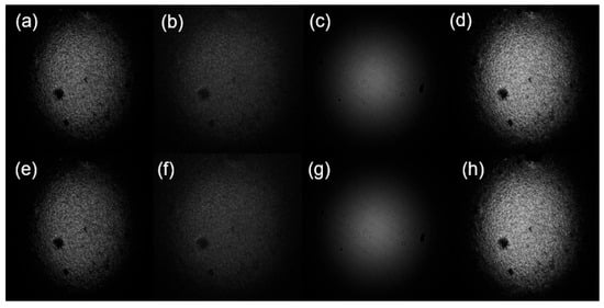
Figure 3.
(a) is , (b) is , (c) is , (e) is , (f) is , and (g) is . (d,h) display one frame of and one frame of , respectively.
The flowchart of our proposed method for obtaining the contour information of the measured object is depicted in Figure 4.
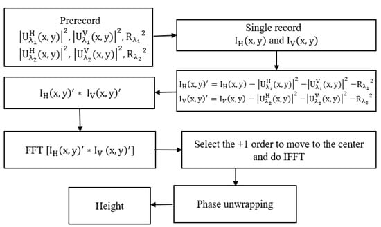
Figure 4.
The compact single-shot dual-wavelength interferometer algorithm flow chart.
According to Equations (7) and (8), the interferogram requires preprocessing by subtracting the object light pattern and reference light pattern. This involves the subtraction of and . The resulting images are depicted in Figure 5a and Figure 5b, respectively. Figure 5c presents the product of Figure 5a,b, revealing interference fringes with noticeable noise.
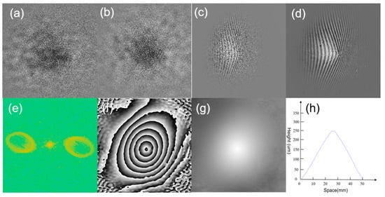
Figure 5.
(a) is . (b) is . (c) Multiplication of (a,b). (d) Filtered fringe pattern. (e) Spectrum after Fourier transform. (f) Wrapped phase. (g) True phase following unwrapping. (h) Vertical line graph.
The parallel fringes, primarily influenced by the 2-degree tilt of the reference laser beam, exhibit deformations corresponding to the surface profile of the sample. Under the condition that the reference mirror be tilted by 2 degrees, the permissible local tilt of the sample needed to be greater than −2 degrees. For a sample with a diameter of 50 mm, the theoretically permissible maximum height at the center is calculated as . To ensure an adequate number of interference fringes in experiments, the maximum height should be significantly less than this theoretical value.
Following Equation (10), the speckle noise apparent in Figure 5c arises from the first term of Equation (10) and can be effectively mitigated by Fourier transformation applied to these fringes, selectively retaining low-spatial components. Figure 5d illustrates the resulting interference fringes after noise removal, showcasing a smooth pattern. The subsequent Fourier transformation of Figure 5d yields its spectrum in Figure 5e. Employing the spatial filtering method to isolate the +1 order spatial components from Figure 5e, relocating them to the center of the computational matrix, and executing an inverse Fourier transform generates the phase diagram of the wrapped surface contour, as depicted in Figure 5f. Figure 5g represents the true phase diagram of Figure 5f, following the unwrapping process, while Figure 5h provides a vertical line graph corresponding to the true phase map. Since the obtained interference fringe pattern in Figure 5d exhibited clarity, the least-squares-algorithm-based phase unwrapping method was applied to compute unwrapped phase maps in Figure 6, prioritizing both high computing speed and accuracy [30]. Spatial filtering and phase computation in Figure 5f could be accomplished with a single Fourier transform, eliminating the necessity of generating the fringes in Figure 5d. The inclusion of the clear interference fringes in Figure 5d serves solely to validate the theoretical analysis presented in Section 3.

Figure 6.
(a–h) Measured phase maps of the plastic sheet when the screw micrometer was 0 um, 30 um, 60 um, 90 um,120 um, 150 um,180 um, and 210 um, respectively. The left and right parts in each figure are wrapped and unwrapped phases, respectively.
To assess the precision of the aforementioned experiment, the screw micrometer was incrementally advanced, inducing deformation in the plastic sheet and changing its surface profile. The screw micrometer was advanced eight times, with each movement covering a distance of 30 um. Consequently, the maximum deformation of the sample between two adjacent measurements was also 30 um. Utilizing the introduced method, we were able to measure the shape of the deformed sheet. Figure 6a–h display measured phase diagrams illustrating surface profiles of the plastic sheet corresponding to eight different screw micrometer positions. In each figure, the left part depicts the wrapped phase, while the right part illustrates the corresponding unwrapped phase.
For quantitative analysis, the values of the unwrapped phase were plotted along dotted lines in each figure of Figure 6, as shown in Figure 7. By comparing the obtained values with those read from the screw micrometer, the measurement error was determined. The maximum value in each figure of Figure 7 and the readings from the screw micrometer were listed in Table 1. These measured deformations were calculated as the difference between two successive peaks of the deformed surface profile, as depicted by the curves in Figure 7. These readings from the screw micrometer were considered as the true maximum deformations of the plastic plate. The comparison of the measured maximum deformations to the true maximum deformation yielded impressive maximum absolute and maximum relative errors, both less than 2 um and 6%, respectively. This result underscores the excellent accuracy of the proposed measurement method in this study.
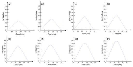
Figure 7.
(a–h) correspond to the vertical scribes positioned at the blue dashed line in Figure 6, respectively.

Table 1.
Eight experimental measurements, true values, and errors.
5. Conclusions
The single-shot dual-wavelength interferometry method proposed in this paper offers a precise solution for measuring the surfaces of dynamic objects with high levels of roughness, particularly on commonly encountered metal and plastic surfaces. By simultaneously capturing two frames of polarization interferograms at two laser wavelengths, subtracting the zero-order intensity from each frame, and then multiplying them, we obtain a processed interferogram at a synthetic wavelength, thereby enhancing the measurement range. This approach facilitates the measurement of surfaces on ordinary metal and plastic materials across a substantial range. This theoretical foundation confirms its principles, while experimental validation demonstrates its feasibility, yielding a relative measurement error of less than 6%.
A distinctive aspect of this single-shot dual-wavelength interferometry lies in its utilization of separated polarization illumination and separated polarization detection, coupled with a monochromatic polarization camera. This approach simultaneously achieves simple optical alignment, a broad measurement range, rapid data acquisition, and straightforward data processing for dual-wavelength interferometry. It enables real-time measurements on large objects with rough surfaces, achieving exceptional accuracy compared to traditional scalar-wave optics-based interferometry.
Moreover, compared to conventional dual-wavelength interferometry or single-wavelength interferometry, where interferograms are recorded sequentially, our proposed method offers significantly higher speeds and can effectively measure dynamic surfaces. Notably, camera pixels with micro polarizers at ±45 degrees were not employed in this study. The signal-to-noise ratio could potentially be improved by implementing these pixels, which would involve rotating the polarization direction of incident light by 45 degrees and adjusting the optical alignment and computing methods accordingly. Furthermore, this proposed method may also have applicability to samples with anisotropic real or imaginary parts of the refractive index, although this aspect was not considered in this current study. The approximation of anisotropy in the refractive index as consistent for two slightly different wavelengths suggests the potential for measuring such samples using this method.
Author Contributions
Conceptualization, Y.Y. and C.L.; methodology, Y.Y., A.S., Z.J. and C.L.; software, Y.Y.; validation, Y.Y., P.Z., F.G., X.H. and C.L.; formal analysis, Y.Y.; investigation, Y.Y.; resources, C.L.; data curation, Y.Y.; writing—original draft preparation, Y.Y.; writing—review and editing, S.P.V., Y.K. and C.L.; visualization, Y.Y.; supervision, C.L.; project administration, Y.Y.; funding acquisition, Y.K., X.H., A.S. and C.L. All authors have read and agreed to the published version of the manuscript.
Funding
National Natural Science Foundation of China (62205126, 62305133); Wuxi Science and Technology Development Fund Project (K20221016); Fundamental Research Funds for the Central Universities (JUSRP123028); Project of the Ministry of Industry and Information Technology of the People’s Republic of China (TC220H05L).
Institutional Review Board Statement
Not applicable.
Informed Consent Statement
Not applicable.
Data Availability Statement
Data underlying the results presented in this paper are not publicly available at this time but may be obtained from the authors upon reasonable request.
Conflicts of Interest
The authors declare no conflicts of interest.
References
- Andrés, N.; Lobera, J.; Arroyo, M.P.; Angurel, L.A. Two-dimensional quantification of the corrosion process in metal surfaces using digital speckle pattern interferometry. Appl. Opt. 2011, 50, 1323–1328. [Google Scholar] [CrossRef][Green Version]
- Georges, M.P.; Thizy, C.; Languy, F.; Zhao, Y.; Vandenrijt, J.F. Digital holographic interferometry and speckle interferometry applied on objects with heterogeneous reflecting properties. Appl. Opt. 2019, 58, G318–G325. [Google Scholar] [CrossRef] [PubMed]
- Cuche, E.; Marquet, P.; Depeursinge, C. Spatial filtering for zero-order and twin-image elimination in digital off-axis holography. Appl. Opt. 2000, 39, 4070–4075. [Google Scholar] [CrossRef] [PubMed]
- Cheng, Y.; Wyant, J.C. Two-wavelength phase shifting interferometry. Appl. Opt. 1984, 23, 4539–4543. [Google Scholar] [CrossRef] [PubMed]
- Jeon, S.; Cho, J.; Jin, J.N.; Park, N.C.; Park, Y.P. Dual-wavelength digital holography with a single low-coherence light source. Opt. Express 2016, 24, 18408–18416. [Google Scholar] [CrossRef] [PubMed]
- Chun, B.S.; Kim, K.; Gweon, D. Three-dimensional surface profile measurement using a beam scanning chromatic confocal microscope. Rev. Sci. Instrum. 2009, 80, 229. [Google Scholar] [CrossRef]
- Sun, D.G.; Shang, H.; Jiang, H. Effective metrology and standard of the surface roughness of micro/nanoscale waveguides with confocal laser scanning microscopy. Opt. Lett. 2019, 44, 747–750. [Google Scholar] [CrossRef]
- Fu, Z.; Geng, Q.; Chen, J.; Chu, L.A.; Chiang, A.S.; Chen, S.C. Light field microscopy based on structured light illumination. Opt. Lett. 2021, 46, 3424–3427. [Google Scholar] [CrossRef]
- Gao, P.; Pedrini, G.; Osten, W. Phase retrieval with resolution enhancement by using structured illumination. Opt. Lett. 2013, 38, 5204–5207. [Google Scholar] [CrossRef]
- Vishnyakov, G.N.; Levin, G.G.; Minaev, V.L.; Tselmina, I.Y. Phase-shifting interferometer for monitoring flat and spherical optical components. J. Opt. Technol. 2013, 80, 316–320. [Google Scholar] [CrossRef]
- Jang, S.; Kim, K.B.; Jung, J.W.; Kim, Y. Enhancement of image sharpness and height measurement using a low-speckle light source based on a patterned quantum dot film in dual-wavelength digital holography. Opt. Express 2021, 29, 34220–34228. [Google Scholar] [CrossRef]
- Huang, M.; Qin, H.; Jiang, Z. Real-time quantitative phase imaging by single-shot dual-wavelength off-axis digital holographic microscopy. Appl. Opt. 2021, 60, 4418–4425. [Google Scholar] [CrossRef] [PubMed]
- Munera, N.; Trujillo, C.; Garcia-Sucerquia, J. High-speed measurement of mechanical micro-deformations with an extended phase range using dual-wavelength digital holographic interferometry. Appl. Opt. 2022, 61, B279–B286. [Google Scholar] [CrossRef] [PubMed]
- Cho, J.; Lim, J.; Jeon, S.; Choi, G.J.; Moon, H.; Park, N.C.; Park, Y.P. Dual-wavelength off-axis digital holography using a single light-emitting diode. Opt. Express 2018, 26, 2123–2131. [Google Scholar] [CrossRef] [PubMed]
- Lee, J.Y.; Jeon, S.; Lim, J.S.; Jang, S.H.; Park, N.C.; Kim, Y.J. Dual-wavelength digital holography with a low-coherence light source based on a quantum dot film. Opt. Lett. 2017, 42, 5082–5085. [Google Scholar] [CrossRef] [PubMed]
- Kumar, M.; Quan, X.Y.; Awatsuji, Y.; Tamada, Y.; Matoba, O. Single-shot common-path off-axis dual-wavelength digital holographic microscopy. Appl. Opt. 2020, 59, 7144–7152. [Google Scholar] [CrossRef] [PubMed]
- Shan, M.G.; Liu, L.; Zhong, Z.; Liu, B.; Zhang, Y.B. Direct phase retrieval for simultaneous dual-wavelength off-axis digital holography. Opt. Lasers Eng. 2019, 121, 246–251. [Google Scholar] [CrossRef]
- Turko, N.A.; Shaked, N.T. Simultaneous two-wavelength phase unwrapping using an external module for multiplexing off-axis holography. Opt. Lett. 2017, 42, 73–76. [Google Scholar] [CrossRef] [PubMed]
- Deng, D.N.; Qu, W.J.; Tang, Q.J.; He, W.Q.; Liu, X.L. Single-shot wavelength-multiplexing for off-axis digital holography with a spectral filter. Opt. Express 2021, 29, 36871–36885. [Google Scholar] [CrossRef]
- Turko, N.A.; Eravuchira, P.J.; Barnea, I.; Shaked, N.T. Simultaneous three-wavelength unwrapping using external digital holographic multiplexing module. Opt. Lett. 2018, 43, 1943–1946. [Google Scholar] [CrossRef]
- Rinehart, M.; Shaked, N.; Jenness, N.J.; Clark, R.; Wax, A. Simultaneous two-wavelength transmission quantitative phase microscopy with a color camera. Opt. Lett. 2010, 35, 2612–2614. [Google Scholar] [CrossRef] [PubMed]
- Shiratori, T.; Kasai, K.; Yoshikawa, N. Color-image reconstruction for two-wavelength digital holography using a generalized phase-shifting approach. Appl. Opt. 2017, 56, 6554–6563. [Google Scholar] [CrossRef] [PubMed]
- Wang, D.; Tian, X.; Xu, P.; Liang, J.; Wu, H.; Spires, O.; Liang, R. Compact snapshot multiwavelength interferometer. Opt. Lett. 2019, 44, 4463–4466. [Google Scholar] [CrossRef] [PubMed]
- Jeon, J.W.; Joo, K.-N. Single-Shot Imaging of Two-Wavelength Spatial Phase-Shifting Interferometry. Sensors 2019, 19, 5094. [Google Scholar] [CrossRef] [PubMed]
- Zhou, H.; Hussain, M.M.R.; Banerjee, P.P. A review of the dual-wavelength technique for phase imaging and 3D topography. Light Adv. Manuf. 2022, 3, 314–334. [Google Scholar] [CrossRef]
- Brun, C.; Buet, X.; Bresson, B.; Capelle, M.S.; Ciccotti, M.; Ghomari, A.; Lecomte, P.; Roger, J.P.; Petrovich, M.N.; Poletti, F.; et al. Picometer-scale surface roughness measurements inside hollow glass fibres. Opt. Express 2014, 22, 29554–29567. [Google Scholar] [CrossRef] [PubMed]
- Zhou, R.J.; Shen, D.R.; Huang, P.; Kong, L.B.; Zhu, Z.W. Chromatic confocal sensor-based sub-aperture scanning and stitching for the measurement of microstructured optical surfaces. Opt. Express 2021, 29, 33512–33526. [Google Scholar] [CrossRef] [PubMed]
- Di, J.; Zhang, J.; Xi, T.; Ma, C.; Zhao, J. Improvement of measurement accuracy in digital holographic microscopy by using dual-wavelength technique. J. Micro Nanolithogr. MEMS MOEMS 2015, 14, 041313. [Google Scholar] [CrossRef]
- Abdelsalam, D.G.; Kim, D. Real-time dual-wavelength digital holographic microscopy based on polarizing separation. Opt. Commun. 2012, 285, 233–237. [Google Scholar] [CrossRef]
- Wang, X.H.; Zhang, Z.H.; Guo, Z.J.; Wang, H.Y. Study on the unweighted least-squares phase unwrapping algorithm. Proc. SPIE—Int. Soc. Opt. Eng. 2010, 7848, 714–719. [Google Scholar]
Disclaimer/Publisher’s Note: The statements, opinions and data contained in all publications are solely those of the individual author(s) and contributor(s) and not of MDPI and/or the editor(s). MDPI and/or the editor(s) disclaim responsibility for any injury to people or property resulting from any ideas, methods, instructions or products referred to in the content. |
© 2024 by the authors. Licensee MDPI, Basel, Switzerland. This article is an open access article distributed under the terms and conditions of the Creative Commons Attribution (CC BY) license (https://creativecommons.org/licenses/by/4.0/).