Abstract
This paper introduces a new safety approach for Optical Wireless Power Transmission (OWPT), a technology that is integral to the new kinds of Wireless Power Transmission technology (WPT). It starts from the fundamental configuration of the current OWPT system, addressing the safety concerns related to lasers by involving laser irradiation hazards, laser exposure regulation and guidelines, and a comparison with other safety methods. A camera-based OWPT safety system focused on the emission control of the light source is proposed, and it utilizes a depth camera and finely tuned computer vision-based control program. Through meticulous system design and experiments, the proposed system can detect moving objects in a limited indoor environment and control the laser/LED light transmission according to the object’s velocity dynamically. Various functions and exclusive improvements towards OWPT operation are mentioned, and Dynamic Safety-Distance is proposed as the core mechanism of the safety system. Through on-site experiments, indoor safety control and system operation’s evaluation are discussed, acknowledging both the advantages and limitations of the proposed safety system. This paper concludes with suggestions for further developments in camera-based OWPT safety incorporating the concept of Automatic Emission Control.
1. Introduction
Wireless Power Transmission (WPT) technology has increasingly captured attention due to its ability to enhance daily convenience by eliminating the reliance on cables and batteries, all while delivering substantial power for efficient device operation [1,2]. This paper centers on Optical Wireless Power Transmission (OWPT), a subset of WPT that utilizes optical waves, typically visible light, to transfer energy from a source to a receiver [3,4,5].
OWPT proves particularly useful in scenarios where traditional wired connections are impractical, such as in space, underwater settings, moving vehicles, and environments populated with numerous small devices [6]. This technology harnesses directed light beams, such as lasers or LEDs, to wirelessly transmit power with high output and conversion efficiency [7,8], offering benefits like extended transmission ranges, precise directional patterns, and absence of Electromagnetic Interference (EMI) [9]. However, the use of lasers in OWPT introduces safety concerns due to the potential hazards posed by concentrated beams of light, necessitating adherence to stringent safety standards, such as those outlined in IEC60825-2021 [10,11]. For example, according to the regulation for laser power-level classifications, the power of a laser that could be freely used without any safety measures defined as “Class 1” should be below a power level of a few megawatts in the case of a narrow beam. Hence, lasers used in OWPT systems aiming to provide higher power levels can harm the eyes and skin or damage objects if exposure exceeds safe limits.
Regulations, standards, and rules are updated periodically to reflect the expansion of applications and technological advancements. Despite recent active research into OWPT, the safety aspects of this technology warrant additional initiatives and exploration [12,13,14]. Recent developments in OWPT have led to the creation of several safety systems tailored to specific factors, each characterized by unique features. These systems are summarized in Table 1. Wi-Charge’s AirCord™ Wireless Technology and a similar system developed by a research group from Tongji University both utilize a technology where power emitters and receivers serve as reflective mirrors, turning the empty space between them into a resonant cavity, akin to a laser device. Both systems ensure safety by adhering to Maximum Permissible Exposure (MPE) regulations; the AirCord™ technology achieves this through extremely short turn-off times to limit exposure, although this may restrict the system’s ability to deliver higher power levels needed for certain applications. Similarly, the Tongji University system promptly halts transmission if an object enters the resonant cavity, stopping beam irradiation within nanoseconds. Additionally, the system from Tongji University supports optical communication, highlighting a dual-function capability that enhances its application scope [15,16,17]. Furthermore, Powerlight Technologies has introduced a system called Light Curtain, which places a harmless optical power beam alongside the main power transmission beam to enhance safety [18]. Another research direction involves using a non-hazardous light source, for instance, infrared LEDs and lasers with a 1550 nm wavelength, representing another promising direction in the OWPT safety for wirelessly powering IoT devices that require low levels of electricity, thus avoiding laser-exposure safety issues [19]. The eye-safe laser wavelengths, researched by Prof. Sweeney, focus on lasers that operate at 1550 nm, which are less harmful to human eyes according to MPE regulation, even when scattered by environmental factors, while providing higher power output. This approach not only aligns with regulatory safety standards but also enhances public acceptance of laser-based power transfer technologies [20]. However, different rules apply to non-laser light sources, including LEDs. Table 1 shows the advantages and the disadvantages of them; each technology has its own limitations or can be applied only for certain OWPT operation environments.

Table 1.
The pros and cons of different OWPT safety technologies.
A safety-first approach is paramount, aiming to reduce any potential laser exposure risk to humans or objects to the absolute minimum. It is essential that the system is robustly engineered to effectively navigate these challenges. This means that the OWPT system will be constructed not just to minimize risks but to eliminate them wherever possible. The system, based on the ideal objective for OWPT safety research, is designed to achieve 0 exposure, where the Maximum Permissible Exposure (MPE) is effectively null, essentially 0 W/cm2 [21]. Recognizing the limitations and also the advantages inherent in other research, an OWPT safety system that incorporates cameras and computer vision is considered attractive.
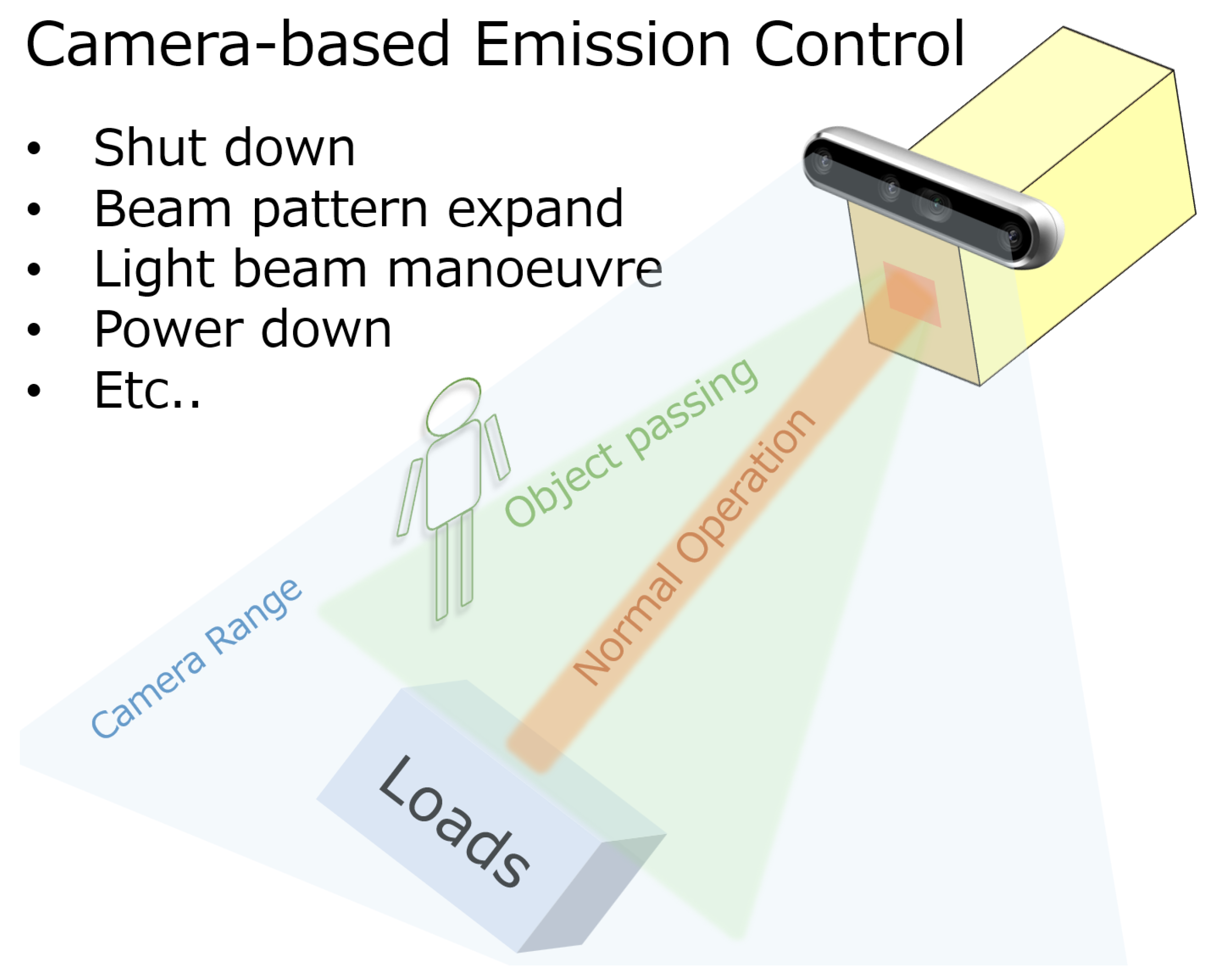
The camera-based safety system offers several distinct benefits, especially in terms of managing the emissions of light sources used in OWPT. The core advantage of this system lies in the Automatic Emission Control. Utilizing object recognition algorithms, the system can dynamically adjust the light output to maintain high power levels, while adhering strictly to MPE or achieving 0-MPE irradiation conditions. This is accomplished by several adaptive strategies: the light beam pattern could be expanded or contract based on the presence and proximity of people or objects, redirect the beam away from sensitive areas to prevent hazardous exposure, or completely shut down the light when necessary, as the schematic in Figure 1 shows. This capability not only enhances safety but also allows for continuous operation without manual intervention, making the system highly efficient. The flexibility to adjust the beam dynamically in response to real-time changes in the environment is a critical feature, particularly in rooms where human activity is unpredictable. The system’s ability to scale by integrating additional cameras provides further customization and coverage, ensuring that larger areas are monitored with the same high level of precision. This scalability makes it ideal for varied installation sites, from small offices to large industrial factories. Moreover, the compactness of the system—with just the camera and a controller PC—is a significant advantage for environments where space is at a premium or where aesthetic considerations are important. Unlike some safety measures that might require bulky physical barriers or significant modifications to the environment, this camera-based system maintains a minimal footprint. However, to fully leverage these benefits, the system’s architecture must be meticulously designed, and the related control program must be finely tuned to ensure responsiveness and reliability. The challenge lies in minimizing latency and effectively adapting to ever-changing environmental conditions, which, if not properly managed, could undermine the system’s advantages and pose potential risks.
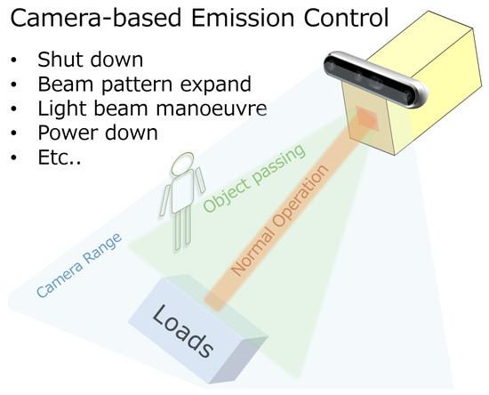
Figure 1.
The light source emission control offered by the camera-based OWPT safety system and the feasible measurements that could apply to the light source.
Building on the background, identified problems, and reported results, the purpose of this study was to develop a foundational OWPT safety system that functions effectively. Specifically, the authors adopted a safety-first approach, utilizing a depth camera and computer vision technologies. Through a sophisticated system design, the fundamental concept of OWPT safety based on a camera was established, and the feasibility of the proposed method was preliminarily confirmed through experiments in a controlled environment. Please note that it is unrealistic to expect a safety system to operate reliably under all usage environments and conditions. Consequently, this study focused on indoor spaces, where a majority of OWPT applications, such as those involving IoT devices, are anticipated to be most prevalent [22,23]. The initial research results related to the contents of this paper were reported in References [24,25]. This paper reports detailed information on the report, as well as newly added research results.
For the content of the paper, Section 2 describes the schematic system design and configuration of an OWPT safety system using Depth Camera and OpenCV. It clarifies the system in detail, with a scheme and its limitations, and covers elements of program logic, target acquisition, coordinates calculation, velocity acquisition, and the building of a proportional–integral–derivative controlled smart car. Section 3 presents indoor safety control and system evaluation through experiments focusing on Dynamic Safety-Distance based on an object’s velocity. The experiments’ configuration, procedure, data processing, and results are analyzed. Section 4 discusses the result of the experiment and clarifies the limitation of the current fundamental research progress of the OWPT safety system, and it points out the future development for the problem that occurred.
2. Scheme of OWPT Safety System Using Depth Camera
First, the proposed OWPT safety system utilizes depth cameras, which offer precise depth detection and a broad field of view. Serving as the “eyes” of the safety system, these cameras enable the system to detect and track objects effectively. By incorporating computer vision techniques, the system can recognize and differentiate between objects, allowing it to make real-time decisions and take immediate actions, such as turning off the light beam or reducing the light power, to ensure a safe operating environment. The safety parameter, termed “Safety-Distance”, is defined to quantify the minimum distance required between an object and the light beam to ensure safe operation of the OWPT system. This section introduces the detailed structure and both the hardware and software configurations of the OWPT safety system.
2.1. Depth Camera-Based OWPT Safety Scheme
In the OWPT safety system, cameras are selected as the critical component due to their capability to provide real-time object detection and recognition independently. These cameras offer a broader detection range, scalability, and advanced real-time analysis capabilities compared to simpler sensors, such as motion sensors used in automatic lighting systems. This makes cameras an efficient solution for compact, integrated safety systems. Additionally, three-dimensional or depth imaging systems have gained popularity recently. Although various methods exist to obtain depth information, in this study, the specific method of acquiring depth data is not the primary concern; rather, the utilization of this depth information is crucial for the effectiveness of the safety system. Moreover, the availability of these camera systems, along with the use of depth information and advanced sensing and control technologies like image recognition, is now sufficiently cost-effective to enable the widespread adoption of this technology [26].
The proposed OWPT safety system is part of the OWPT system, as Figure 2 shows; it combines with the light beam control system and works corporately to turn on/off the light source and maintain the safety operation. In the experiment, the control computer is a personal computer (PC) with CPU of Intel i7-7700HQ, which is limited in regard to its computational resources, just as a usual miniPC. This limits the recognition and control speed; however, it is expected that the cost performance of the PC will improve continuously as technology advances.

Figure 2.
The OWPT safety system configuration consists of safety control unit, which is the main related content in this research. The power unit consists of a laser with visible or invisible light. The receiver unit of solar cell works at the corresponding wavelength.
As a depth camera, the Intel RealSense™ D435 depth camera is used here. Table 2 shows the specification of camera’s two main video streams, the depth and the color stream. The depth detection range of the D435 is up to 10 m, and the minimum is approximately 0.3 m. The field of view of the camera is 87° × 58°, and the maximum frame rate is 90 fps. The D435 system outputs a 30 fps and 640 × 480 resolution video frame stream. It has a best of <2% depth information error rate at a 2–3 m depth. Since the D435 depth camera has severe depth information fluctuation if the distance goes farther, in this research, the detection range was controlled within 3 m as the initial research; thus, high accuracy was assured in order to provide a detailed analysis of the safety technology [27]. The performance of the RealSense camera can be significantly influenced by ambient lighting conditions. Measures were taken to control lighting variability by shielding windows to block out natural sunlight. This precaution was crucial to maintain a consistent artificial lighting setup that supports the functioning of the camera at 30 frames per second. Such controlled conditions are essential to prevent fluctuations in data quality that could arise from changes in lighting, thus directly impacting the reliability and accuracy of the camera’s measurements.

Table 2.
The parameters of the RealSense camera D435.
The powering unit, comprising the light source and the lens system, is the central component that converts electricity into a light beam. In this research, the light source utilized was not a laser but an LED light. This choice was made because the actual laser beam and power transmission are not necessary to validate the operation of the safety system. For convenience and simplicity in deploying and recognizing the light beam’s activation and deactivation, visible LED light was used in the experiments. The LED light source employed is a stage spotlight, which communicates with a PC via serial port signal (RS-232C) using 115,200 bps, similar to the control method for laser devices. This light source can alter the beam size, intensity, and direction through a two-axis mount with it equipped. Control commands and signals are sent directly and received using the computer’s serial signal port, which represents the simplest and fastest method to reduce hardware latency costs. When the constructed safety system is integrated into the practical OWPT system, the light source will be replaced with a laser light source. Regarding the LED light source used, the lens system enables the light irradiation to be output in a uniform shape. Although focusing conditions are typically controlled by standard lens adjustments, in this study, the focusing condition was not adjusted. Such control over focusing and the beam shape is crucial in practical OWPT systems, where some systems use liquid lenses to adjust the focus point of the light irradiation pattern dynamically for high-speed tracking [28].
The receiver side of the OWPT system is a commercial Si-based or GaAs-based solar cell that captures the light with almost the same wavelength from the light emitter [29]. The loads are usually directly connected with the solar cell to feed on the electricity it converts back from the received light. However, in this research, the receiver was not set, because the light beam control is the important target of the safety system.
2.2. OWPT Safety System Operation Process
The operation of the OWPT safety system is depicted in Figure 3, which illustrates the basic components of the system. In the object-recognition process, a background subtraction method is employed to identify objects. This method involves continuously comparing the initial background image with the real-time image stream to distinguish between the object and the environment [30]. Further details of this process are described below.

Figure 3.
The operation flowchart of the OWPT safety system.
Initially, in the frame input process, the depth camera generates color and depth maps of the area within its field of view. Utilizing the RealSense library, the system processes these two video streams and aligns their pixels. This alignment is accomplished by reprojecting the depth data onto the color image. The RealSense SDK is responsible for handling the reprojection, transformation, projection, and interpolation of the depth map. Consequently, a new color frame stream is produced, with each pixel now containing depth information.
The frame processing and object detection begin by applying thresholding to the aligned stream, resulting in an image stream where only the object is visible. This occurs because the background image remains constant each time the camera activates, and the background distance is predefined based on the environment. Grayscale conversion and thresholding are then applied to the aligned frames to create a binary representation, which simplifies the object detection process. Using the contour drawing function from the OpenCV library, a bounding box is drawn around detected objects, providing pixel coordinates of the object and enabling the acquisition of corresponding depth information [31]. In the pursuit of highly accurate depth information, the proposed system employs an average depth methodology. This involves a pixel-by-pixel analysis within the bounding box around the detected object. A filtering mechanism is implemented to exploit variations in depth data, using significant differences in depth values to eliminate background noise and enhance depth accuracy. Consequently, this method achieves high accuracy by considering only the depth information pertinent to the actual object. Furthermore, the surfaces of the detected objects are not uniformly flat, and the depth at different parts may vary. Therefore, the average depth value of pixels on the object is calculated using Equation (1) to obtain a unified depth value for the object. The frequency of this information update matches the frame rate.
where is the depth value at pixel , and is the number of pixels within the recognition box. The pixels and the averaged depth information are then translated to real-world spatial data. This translation is vital for the accurate determination of the object’s proximity to the light transmission center. In the practical OWPT system, the light beam will have its own width or diameter. In this time, the beam width is assumed to be zero for fundamental demonstration, although the LED beam has a wide beam size. Depending on the practical system, the actual beam width should be considered. The system’s light control logic is designed to deactivate the laser when an object breaches the predetermined safety threshold, thus ensuring immediate hazard mitigation. Conversely, the system permits the light to remain active when the Safety-Distance is not compromised, thereby balancing power transmission operational efficiency with rigorous safety protocols.
2.3. Dynamic Safety-Distance
The depth map stream provided by the RealSense camera is crucial for data processing, as it indicates the distance from the camera to objects within its field of view. Each pixel in the depth map corresponds to a specific distance measurement. After isolating the relevant pixels associated with an object identified in both the color and depth maps, the process involves calculating the real-world coordinates of these points. The RealSense SDK facilitates the transformation of 2D pixel coordinates from the depth map into 3D points within the camera’s coordinate system. This transformation depends on the camera’s intrinsic parameters and its distortion model to accurately reverse project the 2D image space into a 3D physical space. The RealSense SDK includes a function that executes this calculation, utilizing the following formula:
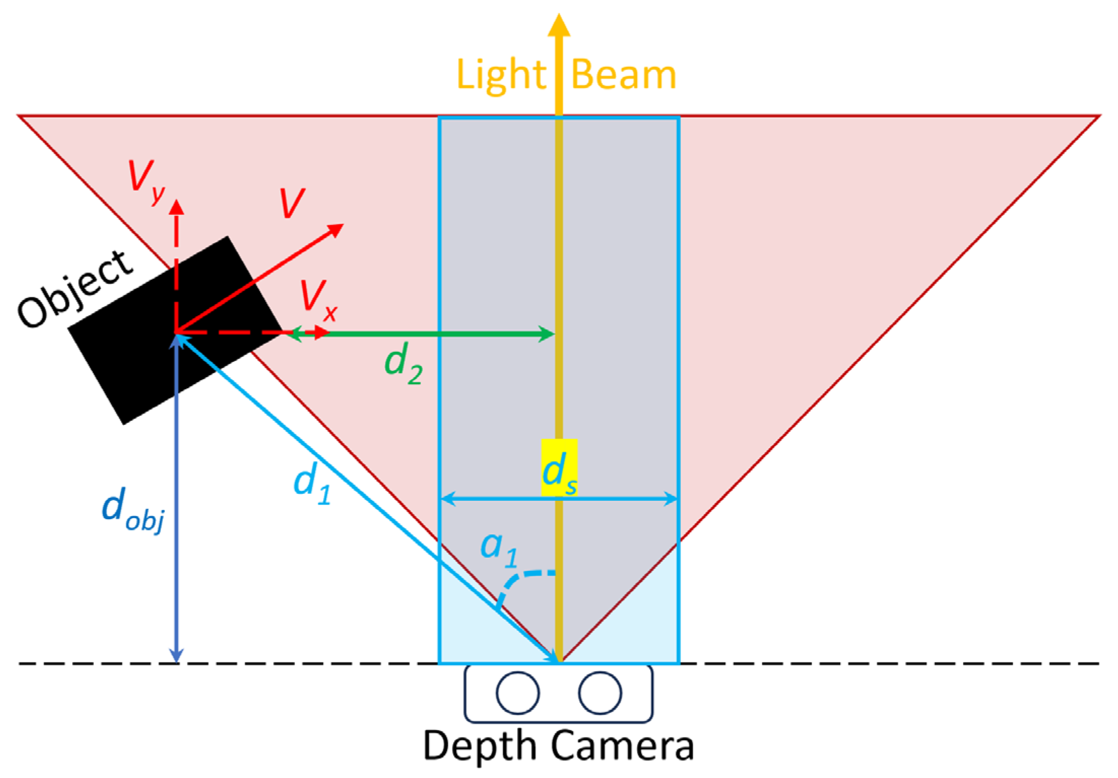
where (X, Y, Z) represents the 3D point within the camera’s coordinate system, (u, v) denotes the pixel coordinates on the image plane, and d refers to the depth value at that pixel. Figure 4 illustrates some key parameters and the model of the Safety-Distance. In scenarios where a conventional 2D imaging system is used rather than a 3D system, the acquisition of precise depth metrics for each pixel within the camera’s visual field is inherently limited. Consequently, traditional 2D vision systems typically establish a precautionary buffer zone that aligns with the camera’s angular field of view, represented by a triangular region, as shown in Figure 4. This approach, however, often leads to an overestimation of the necessary safety margins, increasing the likelihood of unwanted deactivation of the light source. Furthermore, in such 2D vision systems, the delineation of spatial zones based on safety considerations, as exemplified by the designated blue rectangular region in the referenced figure, is prone to significant inaccuracies. It is within this context that the present study advocates for the adoption of a 3D depth camera to enhance the precision of spatial analysis. With the real-world location of each pixel in the frame and embedded with depth information, the distance between any two points or the displacement of any moving points belonging to a moving object is feasible. From this process, several parameters are obtained, as shown in Figure 4.
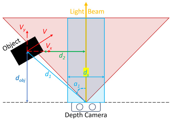
Figure 4.
The Safety-Distance model of OWPT safety system, showing the parameters between object and the light beam in the camera viewing field.
Here, the red shadow area is the viewing field of the camera; the black solid rectangle is the object that entering the detection area; the blue empty rectangle represents the absolute safety area; v and its x and y vectors are the velocity parameters of the object; is the direct distance between camera and the object; is the dynamic angle between the light beam path and direct distance ; is the distance between object and the laser light beam, which can also be shown as d obj to light; and ds is the distance that the light should be shut down before the reaches this value. The value of is defined as the Safety-Distance. The Safety-Distance is the preset minimum distance between the object’s edge and the light beam when the light is cut off. This value defines an area surrounding the light beam, and this area ensures the safety of the OWPT system. Any object that attempts to trespass into this area will cause the suspension of the light transmission.
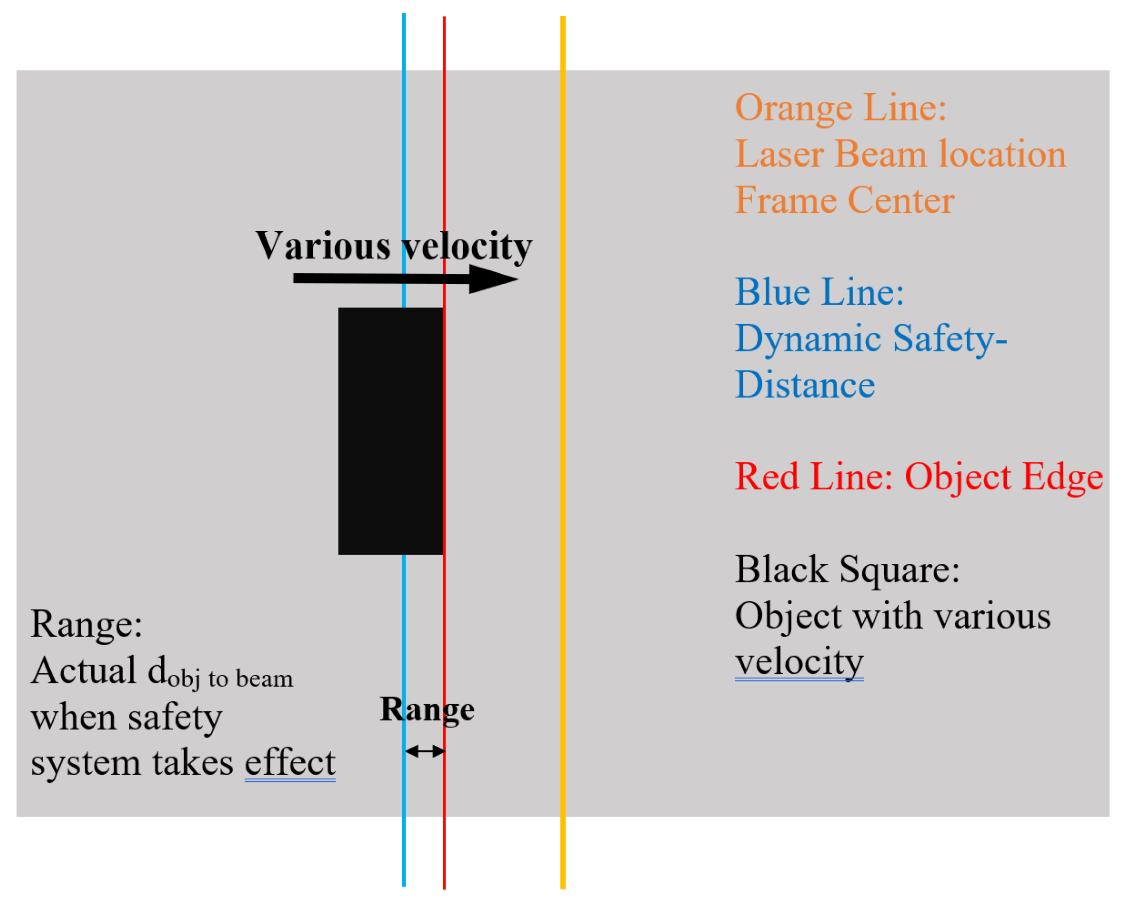
By pre-assigning a Safety-Distance value, the system is programmed to shut down the light immediately upon detecting an approaching object before it reaches the Safety-Distance. Although the system initially uses a preset value for certain fixed distances, the inherent latency of the system—including hardware and object-recognition program processing delays—causes the actual light shutdown to occur closer than the preset Safety-Distance. This shorter distance between the light and the object at the time of shutdown is referred to as the Actual Safety-Distance. As illustrated in Figure 5, the blue line represents the preset Safety-Distance, and the latency influences the range value, leading to the emergence of the actual Safety-Distance value. This value is critical for analyzing system performance and must be considered when designing the Safety-Distance-based light-control logic.
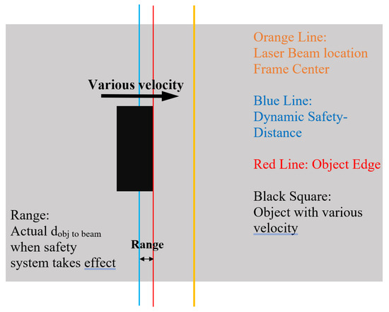
Figure 5.
The schematic illustration for introducing the existence of the Range value; it is caused by the system latency.
The fixed Safety-Distance was initially explored as a fundamental solution to validate the OWPT safety system. It was found during testing that this approach could not adequately handle variable situations due to its lack of flexibility, particularly when the object’s movement is too fast or too slow. Since the Safety-Distance is always set to the same value and the system latency tends to be stable, if the object moves too rapidly, it could pass through the light beam due to the insufficient Safety-Distance.
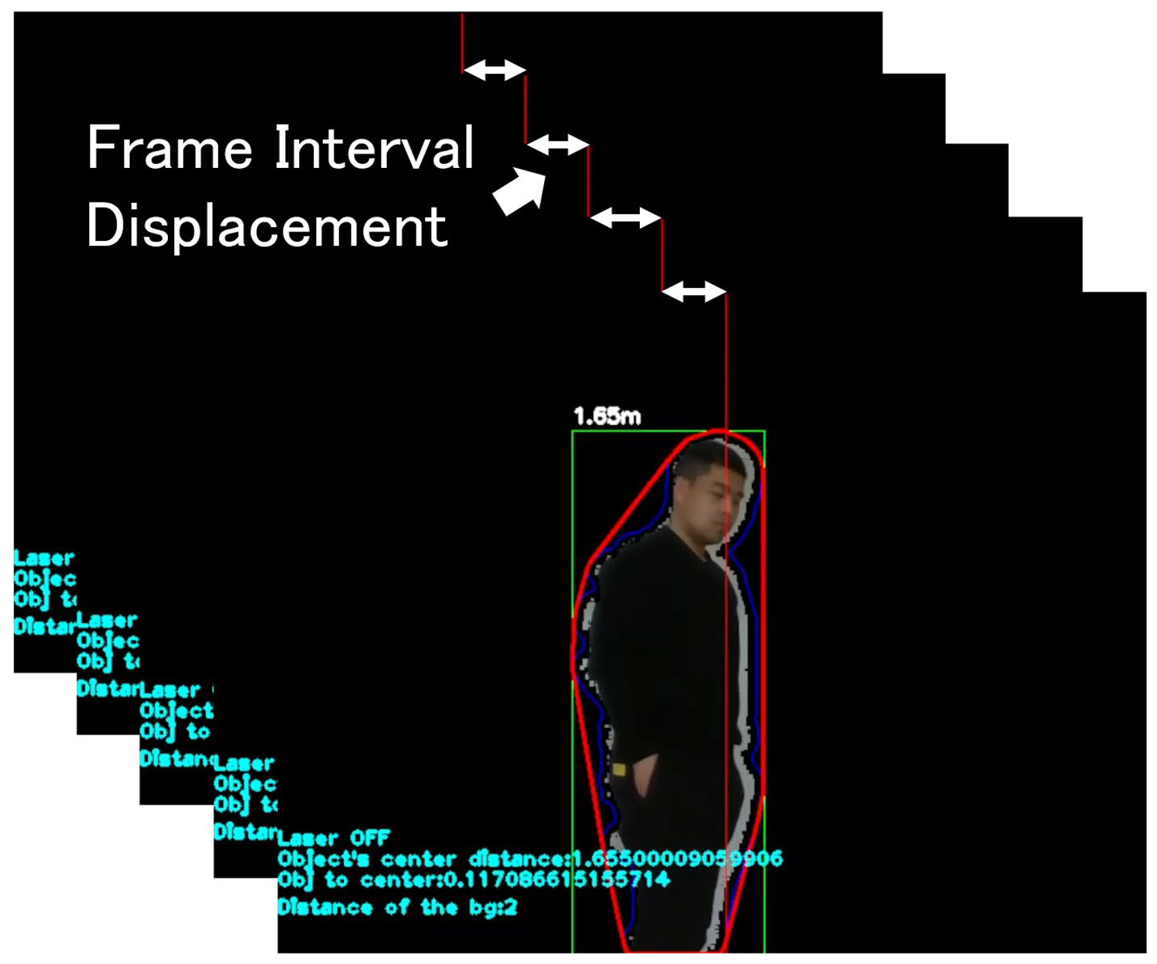
Consequently, the velocity of the object has become a crucial parameter for dynamically controlling the Safety-Distance when managing the light source. The term “dynamic” here implies that the system automatically determines the necessary Safety-Distance to shut down the light transmission in time, based on the real-time velocity of the detected potential trespassing object. Utilizing the parameters acquired, the displacement of a pixel can be calculated for each frame interval, as shown in Figure 6.
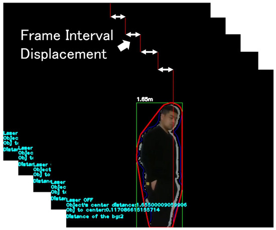
Figure 6.
The frame interval displacement that is used to calculate the velocity of a sample point belongs to the detected object, thus obtaining the object’s velocity.
The Euclidean distance formula is used to calculate the direct real-world distance between any two points. The previous is also calculated using this formula, using the object sample point and light beam location, which is the center point . We must assume that any two points are and . The distances and are shown as Equations (3) and (4) below:
Then, the frame interval-based 3D space location difference can be calculated for each frame, for example, 30 frames in 1 s. The velocity of the object is continuously calculated by the displacement of the object between every two frames when the camera works. The velocity for every 2 frames using the function (5) under the case of 30 FPS is determined as follows:
It calculates the speed of the object given the displacement over frames of 30 frames in 1 s. Meanwhile, the safety system will include the overall operation latency, , of the entire safety system, which is the sum of the safety system program code runtime, the shutdown time of the connected hardware of the light transmission devices [32]. The Dynamic Safety-Distance of the system can be calculated by multiplying these two parameters as follows:
The system continuously compares the object-to-beam distance () with the Safety-Distance () in real-time. If is greater than the , the light beam is turned off immediately. Employing the Dynamic Safety-Distance approach offers several advantages. Firstly, in the actual OWPT working environment, the potential trespassing objects—typically humans walking or unmanned devices in indoor spaces—exhibit completely random speeds, presenting a challenge for automated control. The Dynamic Safety-Distance approach addresses this variability by adaptively adjusting the Safety-Distance values, demonstrating enhanced robustness and flexibility. It autonomously selects an appropriate Safety-Distance based on the recognition results, effectively handling challenges posed by varying object velocities, whether they are too fast or too slow. The system is designed to ensure basic safety functionality within a limited indoor environment, accommodating objects moving straight through the camera’s recognition range at speeds not exceeding 3 m/s (10.8 km/h). This speed limit corresponds to the upper mobility limit of a PID-controlled car and the typical walking or running pace of humans in an indoor environment. This specification outlines the primary safety objectives that the system aims to fulfil.
On the other hand, it should be noted that this Dynamic Safety-Distance method allows the light source to be turned off appropriately even for relatively slow-moving objects. With a fixed Safety-Distance, the light beams are turned off a long time in advance, especially for slow-moving objects, but with a Dynamic Safety-Distance, the unnecessary light-off time can be greatly reduced.
3. Evaluation Experiment and Results
To evaluate the safety system and simulate the indoor environment in which the OWPT will be implemented, two sets of experiments targeting a maximum depth distance of 2.5 m were conducted. Initially, the fixed Safety-Distance method was developed to assess the influence of system latency, and a corresponding experiment was carried out. Subsequently, based on the mechanisms employed in the initial experiment, and considering the results and issues encountered, a dynamic safety system was developed. This system, which adjusts based on the object’s velocity, was designed to fulfill the fundamental requirement of ensuring safety during OWPT operations.
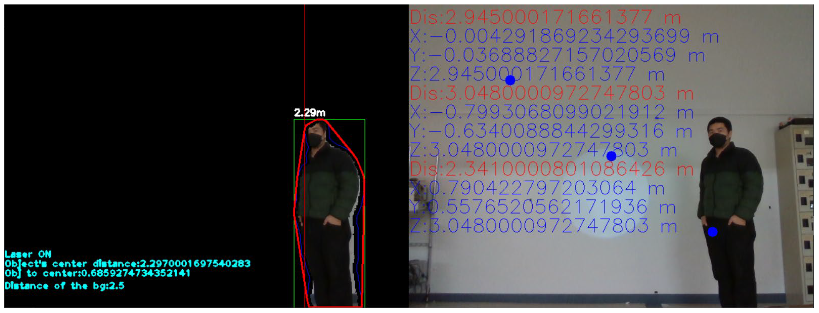
Essentially, the operational logic of the system remains consistent. Figure 7 illustrates the three stages of a single trespassing event by an intruding object and the corresponding response from the safety system. Firstly, the object enters the recognition area but does not reach the Safety-Distance region, thus allowing the light to continue operating. Subsequently, as the object enters the Safety-Distance and is detected by the system, the is found to be smaller than the calculated Safety-Distance, thus prompting the LED to be cut off. Finally, as the object continues to move, the light is reactivated once the object exits the Safety-Distance range surrounding the light beam. The experimental setup records several critical parameters, such as the calculated Safety-Distance and actual Safety-Distance, as well as the object’s location, its velocity over time, and its time stamps. These data were collected for an analysis to demonstrate the performance of the system.
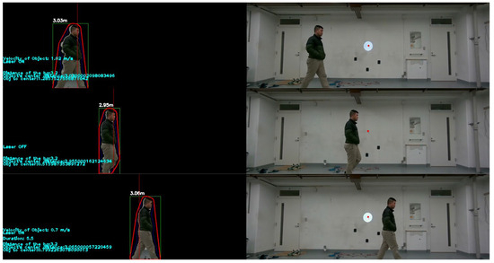
Figure 7.
The 3-stage process of a single intrusion object, including the approaching Safety-Distance area, passing through the light beam and leaving the safety area.
3.1. Fixed Safety-Distance Experiments
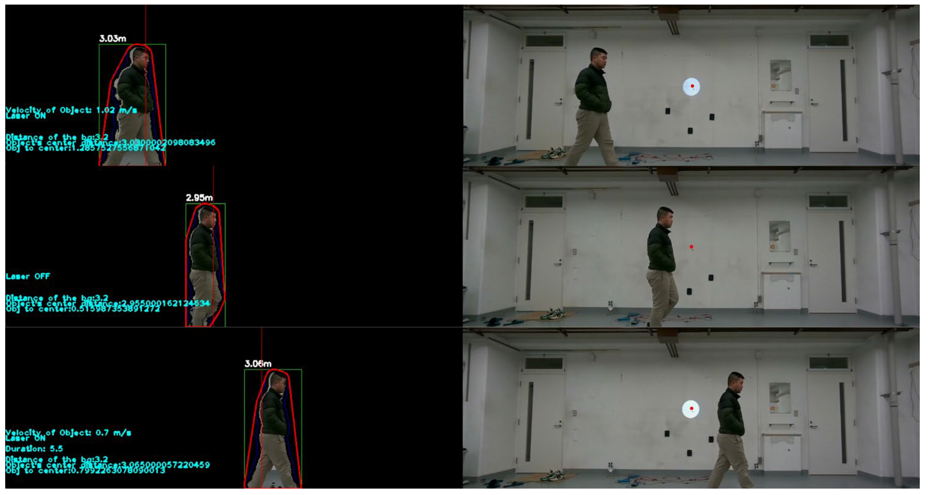
The system employs the RealSense D435 depth camera working under a 640 × 480-pixel resolution, and the recognition area is 3.5 m wide and 2.8 m high. The frame speed is 30 frames per second. The LED light source irradiates a round light pattern, and the location of the light source is at the same horizontal axis as the depth camera. The LED light is connected via a serial port to the control PC, and the serial port signal is used to turn on/off the light. During the experiment, out of convenience and potential risk, the LED stage light was used as the light source to perform a large number of repeat experiments. Figure 8 shows a human walking at different speeds into the recognition.
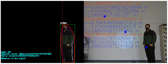
Figure 8.
A frame screenshot from the detection of a human as the recognition object from the fixed Safety-Distance OWPT safety system.
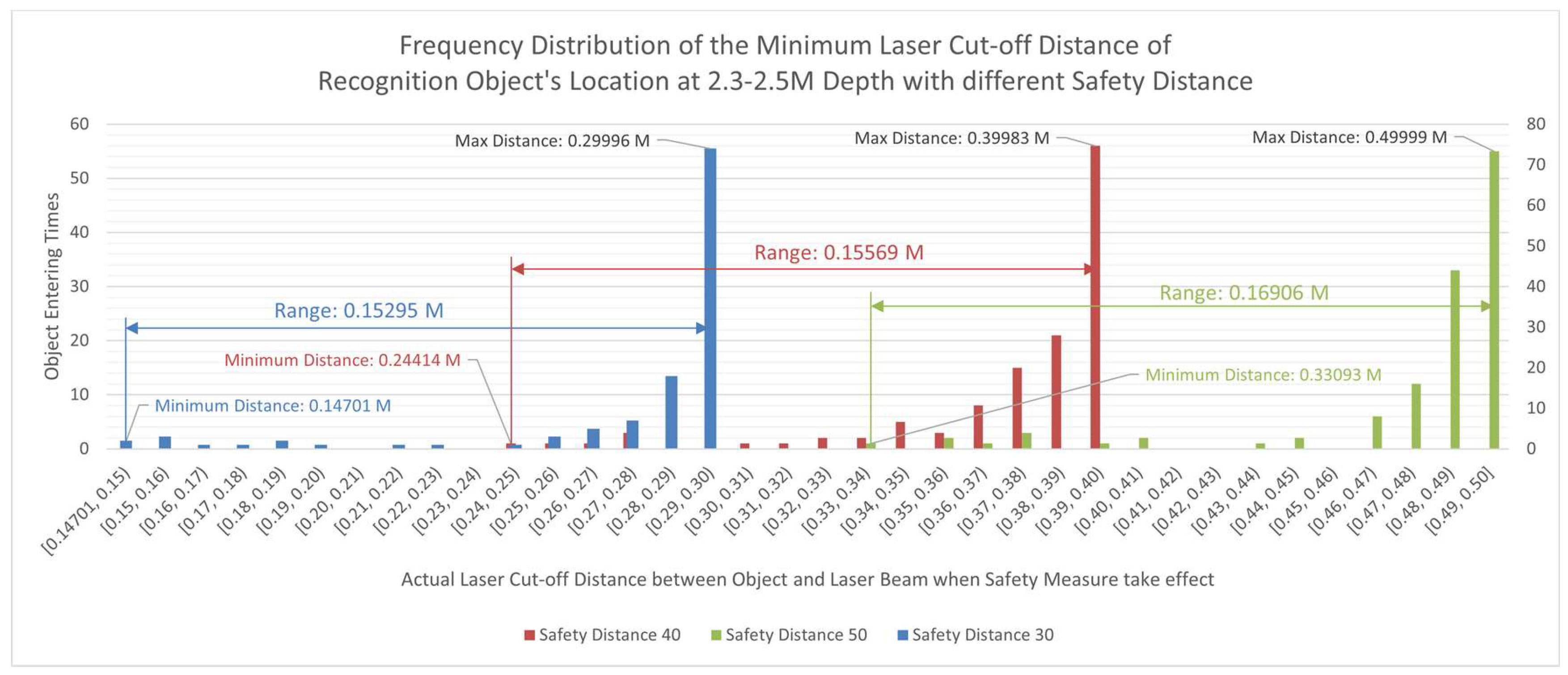
The OWPT safety system took action when the distance between the object and the beam became very small or smaller than the Safety-Distance that was previously defined. Therefore, the safety is ensured before an object touches the beam. The actual Safety-Distance becomes an important value in evaluating the system operation performance. Although the Safety-Distance is a preset value, the parameter of the actual Safety-Distance is recorded every time the light status changes. Meanwhile, the actual position of the object when the light is cut off is different from the preset Safety-Distance, and it is called the Range value. The schematic in Figure 5 illustrates this mechanism. As an object enters the safety system’s operation field, a Safety-Distance value is calculated for every frame. However, when the safety system mechanism takes effect, because of the system delay, the object is already ahead of this preset Safety-Distance, and its edge position is closer to the light beam. To investigate how large the Range value will be in different situations, various preset Safety-Distance values were proposed and used, which are 30 cm, 40 cm, and 50 cm. Various depth locations were set to analyze the safety system in detail: 0.2–0.3 m, 0.5–0.6 m, 0.9–1.0 m, 1.3–1.5 m, 1.8–2.0 m, and 2.3–2.5 m. In these sets of depth, the depth closer than 1 m is considered to be a close depth, and a depth further than 1 m is considered to be a mid-to-long depth. As shown in this experiment, the main target object is assumed to be the size of a human. On the other hand, depending on the camera resolution and recognition error range, smaller moving objects can also be treated in this system. For each group of depth, the object passes the detection area from left to right or right to left, with different speeds, 120 times. The program recorded the 120 times’ minimum Actual Safety-Distance. These data are recorded when the light is cut off.
From Figure 9, we can see the frequency distribution of the minimum light cut-off distance of the recognition object’s location at 2.3 to 2.5 m depth with different fixed Safety-Distance values of 30 cm, 40 cm, and 50 cm. The X-axis shows the actual Safety-Distance. The Y-axis shows at which of the 120 entering times the actual Safety-Distance falls in each section, from the minimum to the maximum value. The trend of the three conditions is quite the same; the similar range value for each group indicates that the system has a unified overall latency, which indicates that a larger Safety-Distance should be set upon the current safety system. Although the velocity was not fixed during the experiments, the data that counted into the frequency distribution were between 0.5 and 2 m/s. The latency level for the fixed Safety-Distance system shares a similar order of 100 ms, as in the previous research. This indicates that there is a relationship between the object speed and Safety-Distance value that should be added to the Safety-Distance calculation function to enlarge the judgment result of the Dynamic Safety-Distance.
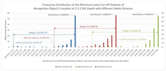
Figure 9.
The frequency distribution of the actual Safety-Distance at a 2.3–2.5 m depth for a total of 360 times for 3 groups (30/40/50 cm) of Safety-Distance values.
Moreover, the fixed Safety-Distance experiment reveals some important problems that could jeopardize the OWPT safety. The system is not flexible enough for handling fast moving objects, as the preset Safety-Distance is always fixed; if the value is too small, the Safety-Distance is not enough for the system to react due to the object’s large velocity. In other words, it can be used only as a test system. However, it confirms the research direction and the strategy for developing a camera-based OWPT safety system. The system was then improved, and the related experiment was also conducted.
3.2. Dynamic Safety-Distance Experiment
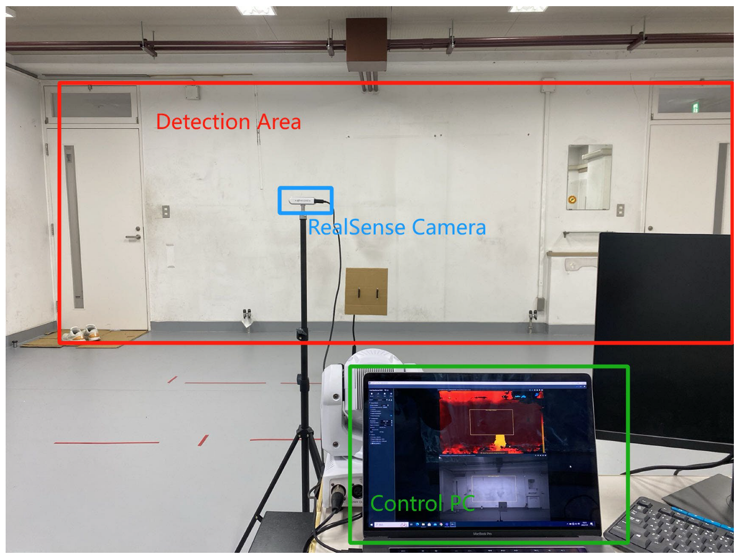
Figure 10 shows the experiment environment of OWPT safety system based on Dynamic Safety-Distance. It is a clean space with a width over 8 m that could support the camera’s resolution with 848 pixels on the x-axis and by placing it 5 m away, towards the wall. For the configuration of the camera, an 848 × 300-pixel resolution color and depth stream were used. The frame speed and LED light used the similar configuration from the previous experiments.
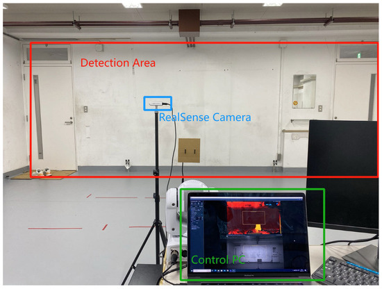
Figure 10.
The limited indoor environment for OWPT safety system operation.
Building upon the insights from the preceding experiment, this study meticulously controlled the object’s velocity to enhance the results’ accuracy and provide a detailed analysis of the system’s latency impacts. Consequently, the evaluation framework for this proposed system was devised by categorizing velocities into distinct groups and pairing them with two depth distance categories. To fulfill the system’s demands, a PID-controlled (Proportional Integral Derivative) smart car, rather than a randomly pacing human, was developed to serve as a controllable object capable of navigating the OWPT operational environment. This vehicle can achieve speeds up to 3 m/s, and its four electric motors, coupled with an independent control board, facilitate precise speed regulation through PID control. Hence, the object’s velocity was meticulously regulated as a controlled variable. The PID-controlled car, equipped with a uniform square paperboard (square paperboard, 30 cm × 30 cm), traversed the OWPT operational field at velocities of 0.5, 1.5, and 2.5 m/s, at depth distances of 1.0 and 2.0 m, conducted twenty times for each condition. The parameters related to the operation were recorded each time there was a change in light status. The experimental setup was implemented as follows:
- 1 m depth distance: 0.5 m/s more than 20 times, 1.5 m/s more than 20 times, and 2.5 m/s more than 20 times;
- 2 m depth distance: 0.5 m/s more than 20 times, 1.5 m/s more than 20 times, and 2.5 m/s more than 20 times.
According from the previous fixed Safety-Distance value and the corresponding velocity group, 20 cm, 30 cm, and 50 cm and 0.5 to 2.0 m/s were used; however, the value was inputted in advance into the program. If the autonomous calculation is going to be deployed, a relation between calculated Safety-Distance and the object velocity needs to be confirmed using the following function:
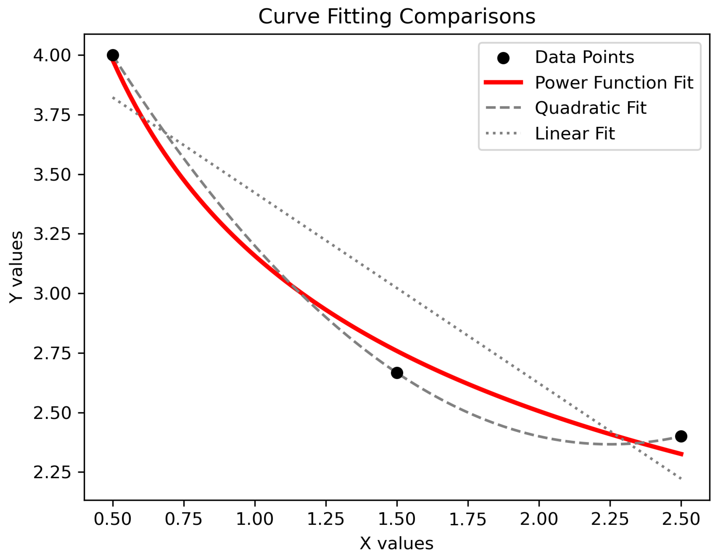
where k is a function that is fitted through referencing the fixed Safety-Distance experiment result value. If the approximate system latency is at the 100 ms level, then the result of the Safety-Distance calculation would be several centimeters, for instance, 5 cm for 0.5 m/s; thus, the result obviously could not ensure safety for the OWPT operation. Also, with the velocity increasing, the calculated Safety-Distance should also increase. Since k is a function that is associated directly with the changing velocity, it needs to be fitted using the most appropriate mathematical model that describes the relationship. From the fixed Safety-Distance experiment result, the 20/40/60 cm corresponding to 0.5/1.5/2.5 m/s velocities and a 100 ms latency value were used to fit the curves.
The linear, quadratic, and power functions were chosen to be fitted, and their comparison is shown in Figure 11. The power function, which has the form , can model a trend in which the k value is gradually decreased in accordance with the increasing velocity; the decreasing rate of the function also becomes slower as the velocity does, thus exactly suiting the needs of the purpose. The linear function could not give an appropriate relation between the needed values. The quadratic function could follow a parabolic trend, but this does not fit the trend that the Dynamic Safety-Distance needs. The red-colored power function curve shows the most appropriate tendency inclination and similarity of the values. The curve is derived as the function below.
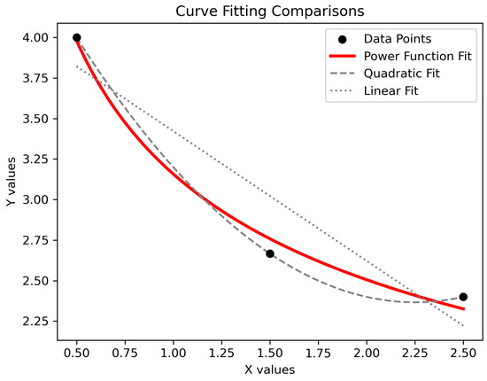
Figure 11.
The curve-fitting result for different attempts. The quadratic function fits the most; however, it does not obey the tendency of the value. The power function curve is adopted as the appropriate function.
In the configured system, the logic for calculating Dynamic Safety-Distance was integrated into the program. Throughout the experiment, two principal parameters were recorded each time the light status changes for experimental evaluation. The first parameter is the calculated Safety-Distance value, while the second is the actual Safety-Distance, which denotes the distance between the object’s edge and the light beam when the light is deactivated, reflecting the system’s overall latency. Additionally, the velocity of the object is documented, with all parameters being timestamped to facilitate the subsequent alignment of various data series.
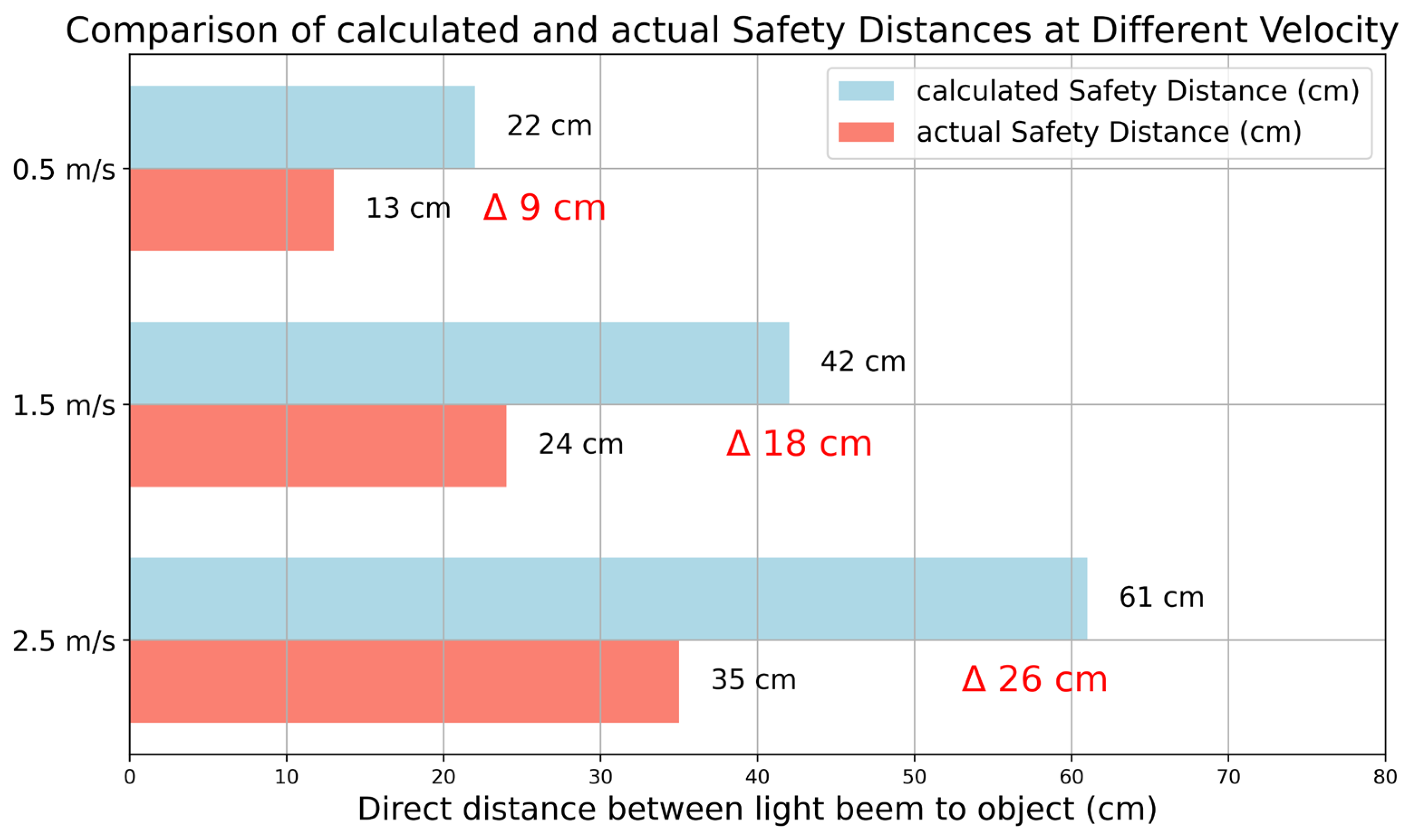
After a series of experiments, the experiment results were processed and are expressed in Figure 12; the data from different groups are averaged to show the overall trends. First, the calculated result of the Dynamic Safety-Distance works well, as its averaged value for three velocity groups is 22/42/61 cm, which is basically authentic to the fitting value for the related curves. The values also show that the system could define a proper longer Safety-Distance together with the increasing velocity of the object. On the other hand, the actual Safety-Distance value is also recorded; under the influence of the system overall latency, the value is marginally smaller than the calculated Safety-Distance, but it still maintains safety, as there is still plenty of space to the light beam. Meanwhile, from the difference value between the calculated Safety-Distance and the actual Safety-Distance, the system’s latency is higher than expected, varying from 104 ms to 180 ms, which indicates that there is still room for space to be improved.
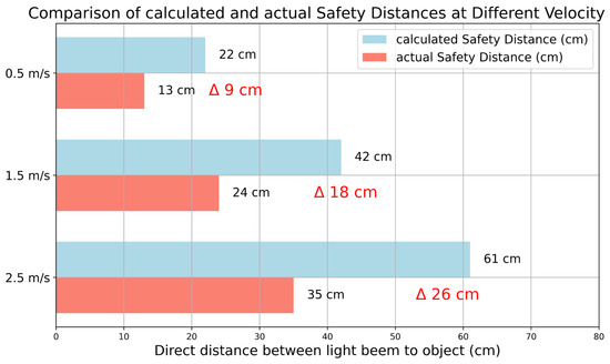
Figure 12.
The result of the calculated Safety-Distance and the actual Safety-Distance at different velocities. The difference between the two values shows that the latency caused a delay in the light control of the system.
4. Discussion
In Section 3, the previously proposed fixed Safety-Distance system for OWPT was initially introduced as a baseline. This research confirms the feasibility of a camera-based safety system for OWPT, thereby laying the groundwork for subsequent enhancements. The dynamic safety system, while utilizing the same object-recognition technique, can be considered an improved system due to significant differences in other components, including parameter sampling, light control, and systemic processing. The system enables emission control automatically by suppressing the light irradiation to 0 on unnecessary objects to fulfill a fundamental but thorough safety. This section also includes discussions on the final version of the dynamic OWPT safety system as it stands at the current phase of the research.
4.1. The Limitation of the Constructed Safety System
As discussed in this research, it can be affirmed that the study of camera-based safety systems for OWPT is still in its nascent stages. Recognizing the need for a more dependable system and incorporating redundancy, a series of comprehensive enhancements should be implemented to enhance the precision and stability of the dynamic safety system for OWPT. The current study was conducted in a controlled and relatively restricted environment, highlighting that variables present in uncontrolled, real-world settings could potentially impact the system’s performance. Furthermore, it would be beneficial to investigate the system’s efficiency with objects moving at higher speeds or in more complex environments, such as scenarios involving objects traversing unpredictable paths. During the experiment, instances occurred—albeit rarely, in just a few cases out of hundreds—where coincidental events posed challenges. For example, if an object stops near the beam, the safety measures triggered by high speed might suddenly become irrelevant, continuing to pose a risk if the Safety-Distance had been previously extended due to high velocity. With no further motion, the system might fail to recognize the need to deactivate, despite the object’s dangerous proximity to the beam.
The current system’s potential for additional revenue is hindered by its lack of support for handling multiple objects. Initially designed to ensure error-free operation in real-world scenarios, the safety system was researched with only a single object due to its developmental stage. However, safety concerns usually arise from the object closest to the beam. This suggests that the system could potentially function with multiple objects in the camera’s field of view. Tests conducted during the experimental phase indicated that the system might operate under limited conditions with multiple objects, although it was not optimized for such scenarios.
Response time is critical in the OWPT system, and to manage risks associated with latency, a Safety-Distance mechanism is implemented. This mechanism compensates for delays by adjusting the Safety-Distance to preserve system safety. While detailed latency investigations were not the focus of this current study, they have been addressed in previous research [32]. Nonetheless, minimizing response time remains a priority for enhancing the OWPT safety system’s efficiency. Currently, the system exhibits a latency ranging from 104 to 180 ms, indicating significant potential for further reduction and continuous optimization.
4.2. Discussion of the Potential Accuracy Improvements
One noteworthy limitation of the current system is its reliance on OpenCV for object recognition. On the one hand, research on the OWPT safety system is still in its infancy. The necessary conditions and standards for such systems have not yet been fully established. To the consideration of the system complexity and the execution of the proposed idea, the OpenCV with background subtraction was used. Although OpenCV has shown effectiveness in controlled experimental scenarios, its performance may falter in more complex environments. Its capabilities in accurately identifying objects under challenging conditions—such as high-speed movements, complex backgrounds, and variable illumination—are somewhat limited. This could potentially compromise the safety of the system. For instance, difficulties in precisely calculating the Safety-Distance with OpenCV could delay the necessary deactivation of the light beam. Moreover, the experimental setup, while rigorously controlled, limits the generalizability of the findings to real-world settings. The discrepancy between the predictable laboratory conditions and the unpredictable variables encountered in real-world environments could lead to deviations in performance when the system is deployed outside controlled settings. In recognition of the advancements in the field of computer vision, future research plans to leverage Convolutional Neural Network (CNN)-based deep learning to enhance object-recognition capabilities.
Unlike OpenCV, CNN-based deep learning excels at managing complex images and dynamically changing environments. The ability of CNNs to learn and discern complex patterns from extensive datasets could markedly improve the accuracy and stability of object recognition. Specifically, CNNs can be tailored to recognize the types of objects that OWPT systems frequently encounter, offering a more robust solution for real-world applications. This shift towards CNN-based technologies reflects a strategic response to the limitations observed with traditional image processing methods in complex scenarios, positioning the system for a more reliable performance across diverse operational environments. However, while CNNs can offer a better performance for complex and dynamic object recognition tasks, they also come with increased complexity and resource demands. The choice between OpenCV and CNNs will be guided by the specific needs of the research and the application it may produce, including considerations of environment, required demands, and available resources.
5. Conclusions
This paper discussed and proposed a safety system for OWPT using a depth camera and computer vision. It is a new approach for the OWPT safety technologies that uses camera and computer vision technology to ensure the safety of OWPT operation. The proposed system was evaluated in terms of its ability and limitation to dynamically adjust the Safety-Distance based on the velocity of moving objects within the OWPT environment. The experiments conducted in a limited indoor setting showed that the system could effectively respond to objects entering the safety zone, adjusting the power transmission accordingly to maintain safety. It validates Dynamic Safety-Distance light control logic under various depth locations (0.5 to 2.5 m depth distance) and intrusion object velocities (0.5 to 2.5 m/s velocity). The results obtained from these experiments have been instrumental in confirming the system’s capabilities. The system showed consistent latency of approximately 100–180 ms, and it is capable of shutting down light transmission before an object moves into the light beam. The proposed and designed system fulfils the basic idea of the OWPT safety, the Automatic Emission Control for the OWPT system that employs a controllable light source. The minimum Safety-Distance value that comes from over 100 repeated experiments is 12.6/24/35 cm, with an object velocity of 0.5/1.5/2.5 m/s within 2 m of depth distance. The Safety-Distance varies according to the velocity of the detected object and provides flexibility in controlling the safety operation of OWPT.
However, the experiments also revealed its limitations. The system’s latency resulted in a delay between object detection and light shutoff, raising concerns about the system’s performance with faster-moving objects or in more complex settings. The observed relatively high latency indicates that further optimization of the system’s response time is necessary to ensure robust safety and reduce the system reaction distance. Also, the safety system developed in this study symbolizes the first step of constructing the OWPT safety technology using a depth camera. The dynamic adjustment of the Safety-Distance based on object velocity has been proved as a promising approach, and it requires future research for perfection and problem solving so that it can eventually be as close as possible to the ideal objective, that is, the error-free and reliable OWPT safety system.
Various systems are being considered for safety mechanisms in Optical Wireless Power Transmission. On the other hand, the standardization of laser safety using Automatic Emission Control (AEC) has started in IEC TS 60825-21 (TC76). The proposals and results of this paper are consistent with the AEC concept, and the authors believe that the results of this study will become one of the mechanisms for the realization of safety standardization.
Author Contributions
Conceptualization, C.Z. and T.M.; software, C.Z.; validation, C.Z.; writing—original draft preparation, C.Z.; writing—review and editing, T.M.; supervision, T.M. All authors have read and agreed to the published version of the manuscript.
Funding
This work was partially supported by JST SPRING, Grant Number JPMJSP2106, and the Tsurugi-Photonics Foundation (No. 20220502). In addition, part of this paper is based on the project commissioned by the Mechanical Social Systems Foundation and Optoelectronics Industry and Technology Development Association (“Formulation of strategies for market development of optical wireless power transmission systems for small mobilities”).
Institutional Review Board Statement
Not applicable.
Informed Consent Statement
Not applicable.
Data Availability Statement
The related experiment data and the source code of the version corresponding to the safety system used in this paper are going to be open-sourced and available on the author’s GitHub repository for anyone who interested in the research, after the publication of the paper. Please check the website or directly email the author for more information. The author’s GitHub link: https://github.com/realzuoc.
Conflicts of Interest
The authors declare no conflicts of interest.
References
- Zheng, Y.; Zhang, G.; Huan, Z.; Zhang, Y.; Yuan, G.; Li, Q.; Ding, G.; Lv, Z.; Ni, W.; Shao, Y.; et al. Wireless Laser Power Transmission: Recent Progress and Future Challenges. Space Sol. Power Wirel. Transm. 2024, in press. [Google Scholar] [CrossRef]
- Song, M.; Jayathurathnage, P.; Zanganeh, E.; Krasikova, M.; Smirnov, P.; Belov, P.; Kapitanova, P.; Simovski, C.; Tretyakov, S.; Krasnok, A. Wireless Power Transfer Based on Novel Physical Concepts. Nat. Electron. 2021, 4, 707–716. [Google Scholar] [CrossRef]
- Miyamoto, T. Optical Wireless Power Transmission Using VCSELs. In Proceedings of the Semiconductor Lasers and Laser Dynamics VIII, Strasbourg, France, 22–26 April 2018; SPIE: San Francisco, CA, USA, 2018; Volume 10682, p. 1068204. [Google Scholar]
- Jin, K.; Zhou, W. Wireless Laser Power Transmission: A Review of Recent Progress. IEEE Trans. Power Electron. 2019, 34, 3842–3859. [Google Scholar] [CrossRef]
- Marko, I.P.; Duffy, D.A.; Misra, R.; Dattani, K.; Sweeney, S.J. Optical Wireless Power Transfer for Terrestrial and Space-Based Applications (Conference Presentation). In Proceedings of the Physics, Simulation, and Photonic Engineering of Photovoltaic Devices XII, San Francisco, CA, USA, 28 January–3 February 2023; SPIE: San Francisco, CA, USA, 2023; Volume PC12416, p. PC1241608. [Google Scholar]
- Van Mulders, J.; Delabie, D.; Lecluyse, C.; Buyle, C.; Callebaut, G.; Van der Perre, L.; De Strycker, L. Wireless Power Transfer: Systems, Circuits, Standards, and Use Cases. Sensors 2022, 22, 5573. [Google Scholar] [CrossRef] [PubMed]
- Zhang, Q.; Fang, W.; Liu, Q.; Wu, J.; Xia, P.; Yang, L. Distributed Laser Charging: A Wireless Power Transfer Approach. IEEE Internet Things J. 2018, 5, 3853–3864. [Google Scholar] [CrossRef]
- Xiao, Y.; Wang, J.; Liu, H.; Miao, P.; Gou, Y.; Zhang, Z.; Deng, G.; Zhou, S. Multi-Junction Cascaded Vertical-Cavity Surface-Emitting Laser with a High Power Conversion Efficiency of 74%. Light Sci. Appl. 2024, 13, 60. [Google Scholar] [CrossRef] [PubMed]
- Lee, C.; Woo, S.; Shin, Y.; Rhee, J.; Moon, J.; Ahn, S. EMI Reduction Method for Wireless Power Transfer Systems with High Power Transfer Efficiency Using Frequency Split Phenomena. IEEE Trans. Electromagn. Compat. 2022, 64, 1683–1693. [Google Scholar] [CrossRef]
- IEC 60825:2024 SER; Safety of Laser Products. International Electrotechnical Commission: Geneva, Switzerland, 2024.
- Henderson, R.; Schulmeister, K. Laser Safety; CRC Press: Boca Raton, FL, USA, 2003; ISBN 978-0-429-14013-6. [Google Scholar]
- Wong, Y.L.; Shibui, S.; Koga, M.; Hayashi, S.; Uchida, S. Optical Wireless Power Transmission Using a GaInP Power Converter Cell under High-Power 635 Nm Laser Irradiation of 53.5 W/cm2. Energies 2022, 15, 3690. [Google Scholar] [CrossRef]
- Yang, Q.; Yang, H.; Wang, J.; Gou, Y.; Li, J.; Zhou, S. Research on the Output Characteristics of Laser Wireless Power Transmission System with Nonuniform Laser Irradiation. Opt. Eng. 2022, 61, 067106. [Google Scholar] [CrossRef]
- Li, X.; Huang, G.; Wang, Z.; Zhao, B. Optics-Driven Drone. Sci. China Inf. Sci. 2024, 67, 124201. [Google Scholar] [CrossRef]
- Alpert, O. Directional Light Transmitter and Receiver. WO/2009/083990, 9 July 2009. [Google Scholar]
- Fang, W.; Deng, H.; Liu, Q.; Liu, M.; Jiang, Q.; Yang, L.; Giannakis, G.B. Safety Analysis of Long-Range and High-Power Wireless Power Transfer Using Resonant Beam. IEEE Trans. Signal Process. 2021, 69, 2833–2843. [Google Scholar] [CrossRef]
- Xiong, M.; Liu, Q.; Liu, M.; Wang, X.; Deng, H. Resonant Beam Communications With Photovoltaic Receiver for Optical Data and Power Transfer. IEEE Trans. Commun. 2020, 68, 3033–3041. [Google Scholar] [CrossRef]
- Kare, J.T.; Nugent, T.J., Jr. Light Curtain Safety System. WO/2016/187345, 24 November 2016. [Google Scholar]
- Zhao, M.; Miyamoto, T. 1 W High Performance LED-Array Based Optical Wireless Power Transmission System for IoT Terminals. Photonics 2022, 9, 576. [Google Scholar] [CrossRef]
- Mukherjee, J.; Jarvis, S.; Perren, M.; Sweeney, S.J. Efficiency Limits of Laser Power Converters for Optical Power Transfer Applications. J. Phys. D Appl. Phys. 2013, 46, 264006. [Google Scholar] [CrossRef]
- Delori, F.C.; Webb, R.H.; Sliney, D.H. Maximum Permissible Exposures for Ocular Safety (ANSI 2000), with Emphasis on Ophthalmic Devices. J. Opt. Soc. Am. A 2007, 24, 1250–1265. [Google Scholar] [CrossRef] [PubMed]
- Zhou, Y.; Miyamoto, T. 200 mW-Class LED-Based Optical Wireless Power Transmission for Compact IoT. Jpn. J. Appl. Phys. 2019, 58, SJJC04. [Google Scholar] [CrossRef]
- Zhou, Y.; Miyamoto, T. 400 mW Class High Output Power from LED-Array Optical Wireless Power Transmission System for Compact IoT. IEICE Electron. Express 2021, 18, 20200405. [Google Scholar] [CrossRef]
- Chen, Z.; Tomoyuki, M. Improvement of Optical Wireless Power Transmission Safety System Using Depth Camera by New Safety Distance. In Proceedings of the 5th Optical Wireless and Fiber Power Transmission Conference, Yokohama, Japan, 18–21 April 2023; Volume OWPT11, p. 05. [Google Scholar]
- Chen, Z.; Tomoyuki, M. Integrative Dynamic Safety System for OWPT: Real-Time Velocity and Distance-Based Safety Control. In Proceedings of the 6th Optical Wireless and Fiber Power Transmission Conference, Yokohama, Japan, 23–26 April 2024; SPIE: Yokohama, Japan, 2024; Volume OWPT06, p. 02. [Google Scholar]
- Zhou, S.; Lu, S.; Maruyama, T.; Zhou, Z. Design of Face-to-Face Optical Wireless Power Transmission System Based on Robot Arm Visual Tracking. In Proceedings of the Optical Modeling and Performance Predictions XIII, San Diego, CA, USA, 20–25 August 2023; SPIE: San Francisco, CA, USA, 2023; Volume 12664, pp. 129–137. [Google Scholar]
- Keselman, L.; Woodfill, J.I.; Grunnet-Jepsen, A.; Bhowmik, A. Intel(R) RealSense(TM) Stereoscopic Depth Cameras. In Proceedings of the 2017 IEEE Conference on Computer Vision and Pattern Recognition Workshops (CVPRW), Honolulu, HI, USA, 21–26 July 2017; pp. 1267–1276. [Google Scholar]
- Zhao, M.; Miyamoto, T. Increased Transmission Distance Range in LED-Based Optical Wireless Power Transmission Using Liquid Lens. In Proceedings of the 2023 28th Microoptics Conference (MOC), Miyazaki, Japan, 24–27 September 2023; pp. 1–2. [Google Scholar]
- Tang, J.; Matsunaga, K.; Miyamoto, T. Numerical Analysis of Power Generation Characteristics in Beam Irradiation Control of Indoor OWPT System. Opt. Rev. 2020, 27, 170–176. [Google Scholar] [CrossRef]
- Piccardi, M. Background Subtraction Techniques: A Review. In Proceedings of the 2004 IEEE International Conference on Systems, Man and Cybernetics (IEEE Cat. No.04CH37583), The Hague, The Netherlands, 10–13 October 2004; Volume 4, pp. 3099–3104. [Google Scholar]
- Bradski, G. The Opencv Library. Dr. Dobb’s J. 2000, 25, 120–125. [Google Scholar]
- XiaoJie, M.; Tomoyuki, M. Safety System of Optical Wireless Power Transmission by Suppressing Light Beam Irradiation to Human Using Depth Camera. In Proceedings of the 2021 26th Microoptics Conference (MOC), Hamamatsu, Japan, 26–29 September 2021; pp. 1–2. [Google Scholar]
Disclaimer/Publisher’s Note: The statements, opinions and data contained in all publications are solely those of the individual author(s) and contributor(s) and not of MDPI and/or the editor(s). MDPI and/or the editor(s) disclaim responsibility for any injury to people or property resulting from any ideas, methods, instructions or products referred to in the content. |
© 2024 by the authors. Licensee MDPI, Basel, Switzerland. This article is an open access article distributed under the terms and conditions of the Creative Commons Attribution (CC BY) license (https://creativecommons.org/licenses/by/4.0/).

