Article

Emission Wavelength Limits of a Continuous-Wave Thulium-Doped Fiber Laser Source Operating at 1.94 µm, 2.09 µm or 2.12 µm

1
French-German Research Institute of Saint-Louis, F-68300 Saint-Louis, France
2
Université de Bordeaux-CNRS-CEA, CELIA UMR 5107, F-33405 Talence, France
3
Exail, F-22300 Lannion, France
*
Author to whom correspondence should be addressed.
Photonics 2024, 11(3), 246; https://doi.org/10.3390/photonics11030246
Submission received: 5 February 2024 / Revised: 29 February 2024 / Accepted: 6 March 2024 / Published: 9 March 2024
(This article belongs to the Special Issue High-Power Fiber Lasers)

Abstract

:
We present a thulium-doped single-oscillator monolithic fiber laser emitting successively at three wavelengths, especially at unusual long wavelengths as 2.09 µm and even at 2.12 µm. The 793 nm core absorption of 8.42 dB/m allows for achieving a slope efficiency higher than 43% both at 1.94 µm and 2.09 µm. The operation of the laser at 1.94 µm, 2.09 µm, and 2.12 µm is compared by using different fiber Bragg gratings to push the limit of thulium ions emission above 2.05 µm. This is the first demonstration of emission exceeding wavelengths of 2.1 µm of an only thulium-doped fiber laser, to the best of our knowledge.

1. Introduction

Both civil and military applications benefit from high-power laser sources based on rare earth ions (or lanthanides) and their physical properties. Lanthanides generally lose three electrons to become trivalent ions. Energy transfers around the incomplete electronic layer are metastable with long lifetimes (milliseconds) at the excited level. This property makes rare earth ions inserted in amorphous host matrices (such as silica glass) very favorable to population inversion and, thus, to amplification processes. Moreover, the insertion of rare earth ions in a silica matrix extends the fluorescence spectrum of these ions, thus featuring broad absorption and emission spectral bands, which is a favorable property for amplification thanks to a larger acceptance of pump light. Furthermore, the laser source spectral output can be tuned which can be an important asset for various applications. For several decades, doped fibers have become very popular in laser development. Ytterbium and neodymium ions can emit around 1 µm when pumped at 976 nm or 808 nm, respectively [1,2,3]. The 1.5 µm region can be achieved using erbium ions pumped at 980 nm [4], whereas terbium pumped in the ultraviolet band (265 nm) tends to emit efficiently in the visible region at 540 nm [5]. In the near-infrared, thulium-doped fibers are generally pumped at 793 nm to emit high powers between 1940 nm and 2050 nm [6], and these wavelengths are perfectly adapted to further pump holmium ions that allow for emitting up to 2200 nm [7].
One can notice that two different lanthanides can emit around 2 µm: thulium and holmium. However, the commercial availability of pump diodes at 793 nm makes thulium-doped fibers easier to pump to achieve the 2 µm band, despite the existence of several possible pumping schemes (pumping at 1210 nm or 1630 nm, for example). The absorption/emission cross sections displayed in Ref. [6] show the large emission between 1800 nm and 2100 nm. This is due to the   3 F 4   3 H 6 transition, represented on the energy diagram (Figure 1a,b) among all the energy transitions of the thulium ion.
Since 2007, thulium-doped fibers have been used in different architectures with the aim of steadily increasing the output power. Figure 2 displays the comparison of the maximum output power of 2 µm fiber lasers in continuous wave regime, demonstrated in the literature, as a function of their emission wavelength. First, single-oscillator lasers in which the thulium-doped fiber was placed in a mirror cavity were developed (red dots in Figure 2) [8,9,10,11,12,13,14]. A maximum output power of 885 W at 2.05 µm was achieved in 2009 in a free-space pumping system with multimode fibers that allow for transporting more power [10].
Among the different architectures, single-oscillator monolithic systems are very interesting, as they are ideal in terms of compactness and robustness. In these systems, the maximum output power reported in the literature was 567 W at 1.97 µm, achieved by Walbaum et al. in 2016 [13]. Master-Oscillator Power Amplifier (MOPA) systems that are composed of a first low-power signal source (single-oscillator laser source or 2 µm diode) and one or more amplification stages were also studied in the literature (black dots in Figure 2) [15,16,17,18,19,20,21,22,23,24,25,26,27,28,29]. The highest output power generated in a monolithic MOPA source so far is 1100 W at 1.95 µm reported in 2021 [26]. The kilowatt-level had already been achieved in 2010 by Ehrenreich et al. at the output of a monolithic MOPA system [15]. More recently, Romano et al. reached 937 W at 2.036 µm at the output of an all-fibered MOPA source [27]. Another solution consists of combining several high-power sources, as seen in Ref. [22] with an output power of 790 W at 1.94 µm. However, incoherent beam combining tends to alter the spatial beam profile. Indeed, the authors measured a beam quality factor M 2 = 2.6 which is far from typical values of sources emitting out of a single fiber ( M 2 1.5 typically). In general, no matter the architecture, one can notice that thulium ions are very propitious for high-power laser emission in the spectral range from 1.94 µm to 2.05 µm.
Usually, we consider that the emission cross section of the thulium ion is not suitable at higher wavelengths and holmium ions are required to emit above 2.05 µm. Nevertheless, the use of holmium doped fibers is more difficult due to the less mature technology of fiber development and the lack of high-power pump diodes at the desired wavelength (holmium pumping is particularly suitable around 2 µm). Therefore, holmium-doped fibers typically require a primary thulium-doped laser as pumping source. However, this implies bulkier and less efficient systems. Nonetheless, some realizations are reported in the literature, both in MOPA (violet dot in Figure 2) [30] and in single-oscillator (orange dots in Figure 2) [31,32,33,34] architectures. The highest output power achieved by a thulium-pumped holmium-doped fiber system was 407 W by Hemming et al. in 2013 [31]. Ten years later, Beaumont et al. improved the slope efficiency of such systems, and preliminary results exhibited a slope efficiency of 60% [34], whereas the numerical study they proposed announces a reachable 70% slope efficiency [33]. The use of commercial 793 nm diodes to pump holmium-doped fibers is possible, although by co-doping holmium fibers with thulium ions. A 1:10 concentration ratio between holmium and thulium ions has been identified as favoring the thulium-to-holmium energy transfer in a fiber laser source that can then be directly pumped by 793 nm pump diodes, analogously to only thulium-doped fiber laser sources [35]. Thulium–holmium co-doped fiber lasers are currently in full expansion, essentially in single-oscillator architectures (green dots in Figure 2) [35,36,37,38,39,40]. The two highest output powers reported in the literature were 262 W from a free-space pumping system [40] and 195 W from the only monolithic all-fiber system ever developed [39].
On the one hand, the holmium ion is known to be more adapted to laser emissions above 2.05 µm due to its typical emission cross section that extends up to 2.2 µm; the literature demonstrates that both holmium-doped fibers and thulium–holmium co-doped fibers show some technological limitations. Indeed, an output power exceeding 400 W has never been obtained so far in the spectral range from 2.05 µm to 2.12 µm. On the other hand, the thulium ion allows for achieving a kilowatt-level of around 2.05 µm. According to the emission cross section of thulium [6], this wavelength is not the most suitable, and exploits only half of the maximum absorption of thulium (around 1900 nm). Regarding the impact of ions on the efficiency of the source, the state-of-the-art indicates that for a wavelength lower than 2 µm, thulium remains the most interesting ion, with demonstrated efficiencies reaching almost 60% in MOPAs. Between 2 µm and 2.05 µm, the use of Tm   3 + doping or Tm   3 + , Ho   3 + co-doping gives comparable results, with a slight advantage for thulium (44% demonstrated at 2.04 µm in MOPA). Beyond 2.05 µm, only Ho   3 + -doped or Tm   3 + , Ho   3 + -codoped fiber laser sources have been demonstrated, for efficiencies remaining around 30%. This distribution of accessible wavelengths demonstrated in the literature according to the type of dopant used is in good agreement with experimental measurements we made of the emission spectra on a Tm   3 + doped (green curves) and a Tm   3 + , Ho   3 + -codoped (blue curves) fiber laser (Figure 3) pumped in free-space. The entire experimental setup is described in Ref. [37]. It consisted of an oscillating cavity made with a piece of the active fiber under test. The emission wavelength was selected by changing the angle of a diffraction grating positioned at one end of the cavity (maximum reflectivity). The other end of the cavity (output coupler) consisted of the active fiber cleaved at 0° (4% of Fresnel reflection). Both the doped and the codoped fibers are double clad with a similar geometry (25 µm core, 300 µm octagonal cladding) and an absorption around 4 dB/m.
Figure 3 shows that for a Tm   3 + -doped fiber pumped at 793 nm, the maximum power is obtained around 1.98 µm. The spectral position of the emission maximum barely changes for the active fiber lengths studied here (310 cm to 488 cm). The efficiency range, defined at 80% of the emission maximum, is observed between 1.93 µm and 2.05 µm, which corresponds approximately to what has been demonstrated in the literature. In the case of a Tm   3 + , Ho   3 + -codoped fiber (blue curves in Figure 3), the experimental measurements show an emission maximum around 2.08 µm for pumping at 793 nm and a fiber of 355 cm in length. The emission maximum shifts towards higher wavelengths when the active fiber is elongated (here up to 590 cm). An efficiency range (defined at 80% of the maximum) gives a spectral coverage extending from 2.02 µm to 2.12 µm, which is also in agreement with what has been demonstrated in the literature. Finally, we observe that the power level obtained with just Tm   3 + doping and a Tm   3 + , Ho   3 + codoping is comparable for longer wavelengths, especially around 2.1 µm. So, an exclusively thulium-doped fiber laser, whose emission is imposed by the means of a bulk mirror or a Fiber Bragg Grating (FBG), should be able to emit at a wavelength higher than 2.05 µm. From Figure 2, we can infer that there is a balance between the advantage of using holmium ions despite their limitations and the contribution of thulium ions at these more uncommon wavelengths.
In this paper, we study a single-oscillator thulium-doped fiber laser operating at several wavelengths. First, the maximum gain of the fiber is experimentally investigated for different fiber lengths. Then, we compare the source characteristics when the wavelength is imposed by a FBG in the common thulium emission band (1.94 µm) and in the common holmium emission band (2.09 µm). Finally, we use a third FBG at 2.12 µm to determine the wavelength emission limit of the thulium-doped fiber and its dependence on the fiber length. Hereby, we achieve a slope efficiency as high as 45.6% at 2.09 µm emission wavelength and we demonstrate for the first time, to the best of our knowledge, 100-W laser emission from an only thulium-doped fiber laser at wavelengths beyond 2.1 µm. This work paves the way to new applications for only thulium-doped single-oscillator fiber lasers such as optical parametric oscillator (OPO)-pumping, which requires wavelengths around 2.1 µm. Needs for OPO and other applications will be discussed in the Section 4.

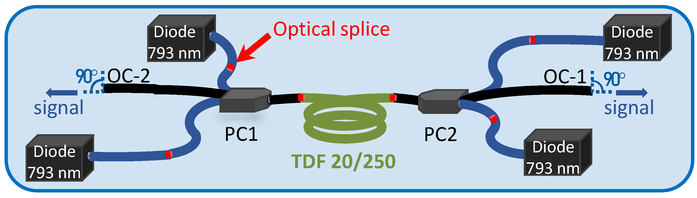
2. Experimental Setup and Cavity Configurations

The experimental setup of the laser is shown in Figure 4. A 5 m long piece of a silica double-clad thulium-doped fiber (TDF) from exail (Paris, France, formerly iXblue Photonics) is symmetrically pumped by two 2 + 1 × 1 fiber pump combiners (PCs) that inject 580 W from four high-power 793 nm fiber-coupled pump diodes. The TDF is radially composed of a thulium-doped core (diameter: 20 µm, numerical aperture NA = 0.09), a germanium-doped pedestal (diameter: 60 µm), and an octagonal-shaped silica cladding (diameter: 250 µm, NA = 0.46). A picture of the transverse section of the TDF is displayed in Figure 5. The core of the fiber is highly doped in order to provide an estimated 789 nm cladding absorption of 8.42 dB/m. This value is calculated from the 1180 nm absorption measured by the manufacturer.
Three high reflectivity (HR) FBGs were used successively to form the cavity with the output coupler (OC), which was a 0° cleave of the PC2 passive (PAS) fiber (4-% Fresnel reflection). The FBG was first removed for the free-running configuration (configuration 1), in which the cavity is simply formed by two cleaves at 0°, leading to two outputs of the laser, which was preliminary used in order to characterize some fiber properties. The four configurations studied in this paper are listed in Table 1. For configurations 2 to 4, the end of the FBG fiber is cleaved at 8° in order to avoid back reflections into the oscillator that could decrease the laser performance. The reflectivity spectra of the three FBGs are displayed in Figure 6. The FBG #1940 (configuration 2) is 3 nm large and inscribed on a 20/250 no polarization maintaining (PM) PAS fiber, whereas the two others (FBG #2090 and FBG #2120), originally made to work with another active fiber, are 1.3 nm large and inscribed on a 20/300 PM PAS fiber. Due to the geometry mismatch, some extra splice losses can appear in configurations 3 and 4.
All the fibered components were fusion-spliced by an arc splicer (FSM-100P+, Fujikura, Tokyo, Japan). Each splice was performed using optimized parameters in order to limit power losses and after a quality check of the cleave (angle measurements and end-face observation with a microscope). The active fiber was coiled to a diameter of 17 cm and placed into a thermal box cooled by deionized water and maintained at a constant temperature of 17 °C. Concerning the measurement setup for the laser characterization, a dichroic mirror was used at the output of the laser to filter the unabsorbed residual pump power (lower than 2 W), and thus to perform optical analyses on the 2 µm output signal. Power measurements are made with a L250 Ophir power meter. Spectral and beam profile measurements are performed using an AQ6376 optical spectrum analyzer (Yokogawa, Tokyo, Japan) and a Pyrocam III camera (Spiricon, Ophir, Jerusalem, Israel), respectively.

3. Results

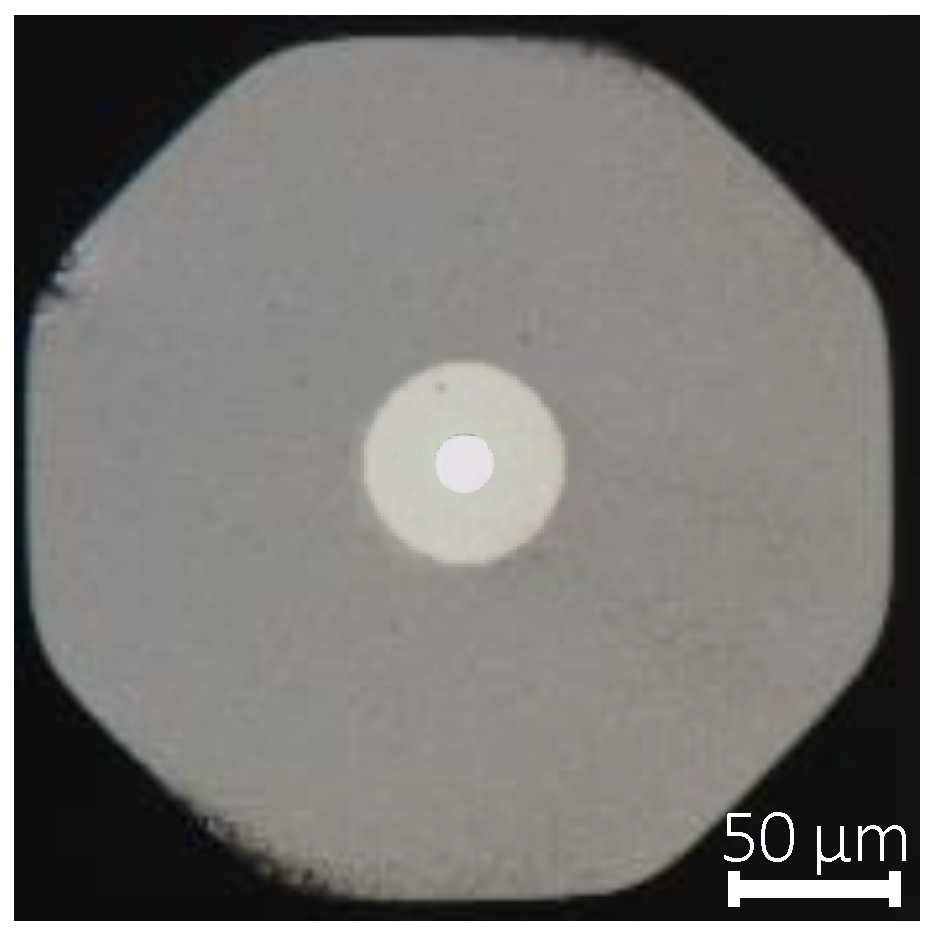
3.1. Thulium-Doped Fiber Characterization

In configuration 1, no FBG is implemented to impose the emitted wavelength (Figure 7). The sum of the two output powers at OC-1 and OC-2 is presented in Figure 8a. At the maximum pump power, an output power of 260 W is obtained, corresponding to 138 W measured at the left output and 122 W measured at the right output. Even if the cavity is totally symmetric here, the power imbalance is due to the slight difference in the intra-cavity splices and the difference of losses generated by each combiner (14.3% for PC1 and 19.7% for PC2). The right output is also more impacted by the second active-passive splice, that creates more losses due to the numerical aperture mismatch (active NA = 0.09 and passive NA = 0.11). Nevertheless, a very high total slope efficiency of 59.1% is obtained.
All the power is emitted at different wavelengths between 2.01 µm and 2.03 µm, according to the normalized output spectrum (Figure 8b). In these free-running cavities, we first measured a large ASE spectrum before a first peak appears when increasing the pump power [39]. After this first emission threshold, several peaks are generated on the entire ASE band. They are not stable, and both their number and their wavelengths change during the power ramping. The wavelength of the highest peak gives information about the maximum gain wavelength of the piece of fiber, depending on the fiber length (approximately 2.02 µm for L = 5 m).
In order to characterize the free-running emission of the fiber over a larger spectral band, a specific experimental setup was developed (Figure 9, inset). It consists of a single-oscillator source in which the TDF is pumped by only one 793 nm pump diode through a 2 + 1 × 1 combiner. The combiner is used to minimize the losses between the diode and the TDF thanks to its adapted fiber dimensions both to the diode and to the TDF. The signal input fiber of the combiner and the output of the TDF are both cleaved at 0° to create a free-running cavity with two outputs. The output OC-1 was sent to the OSA and the output OC-2 was sent to a beam dump. When increasing the diode current (and so the pump power), we began to measure the ASE signal as a large band emission. Then, a first laser peak appears (at the laser threshold) before the apparition of a multitude of peaks, as seen in Figure 8b. To measure the maximum gain wavelength of the fiber piece under test, we recorded the wavelength at the laser threshold. The measurement was performed for pieces of fiber from 9 m to 0.5 m long (Figure 9).
The laser emission is shifted to longer wavelengths when increasing the fiber length. Despite a lot of variance in the measurements attributed to the dependence of the free-running laser emission to environmental conditions as the spooling of the fiber after each cut-back, we can presume an asymptotic behavior in which the central wavelength is limited to 2.05 µm for a piece of fiber longer than 7 m. For very short fiber lengths, the laser emits between 1.97 µm and 2.04 µm. However, with such shorter lengths, the injected pump is not entirely absorbed by the fiber core at the pump level of our experiment (450 W). The pump is mostly absorbed for lengths exceeding 3 m (less than 2 W of residual output pump power measured at the output of the TDF), according to the 8.42 dB/m absorption of the fiber at 793 nm.
The configuration in which the fiber length is adapted to match its maximum gain wavelength with the FBG reflectivity spectrum allows for benefiting from the secondary cavity formed by the two 0°-cleaved angle to enhance the laser performance. An increase in the laser efficiency of 9 percentage points was reported by matching the two parameters in Ref. [41]. However, these results demonstrate the impossibility to adapt the fiber length in order to make the maximum gain corresponding to the wavelength imposed neither by the FBG #1940 (too short fiber needed to absorb the pump) nor by the FBGs #2090 and #2120 (asymptotic behavior in Figure 9). The mismatch between the FBG and the maximum gain wavelengths will slightly impact the laser efficiency and implies the need to cleave the end of the FBG fiber (main setup, Figure 4) at 8° to avoid a parasitic cavity that might disturb the laser power scaling. In the following part, the fiber length of 5 m is maintained to compare the three FBG-OC configurations. Note that the combiner PC2 was burnt during the experimentation and was replaced for the rest of the study by a combiner made on a PM 20/250 passive fiber. It generated equivalent losses (19%), and thus had no impact on the power evolution of the laser. However, the presence of boron stress rods on this part of the cavity may influence the polarization behavior of the laser.

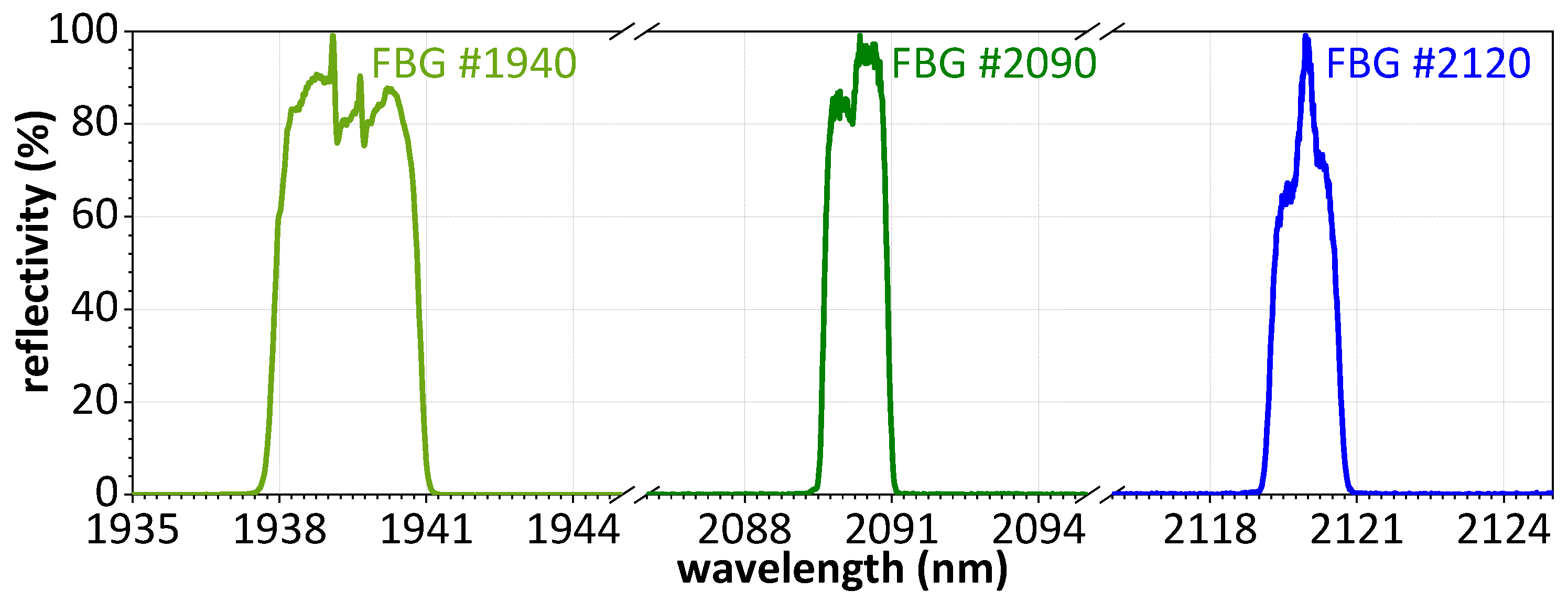
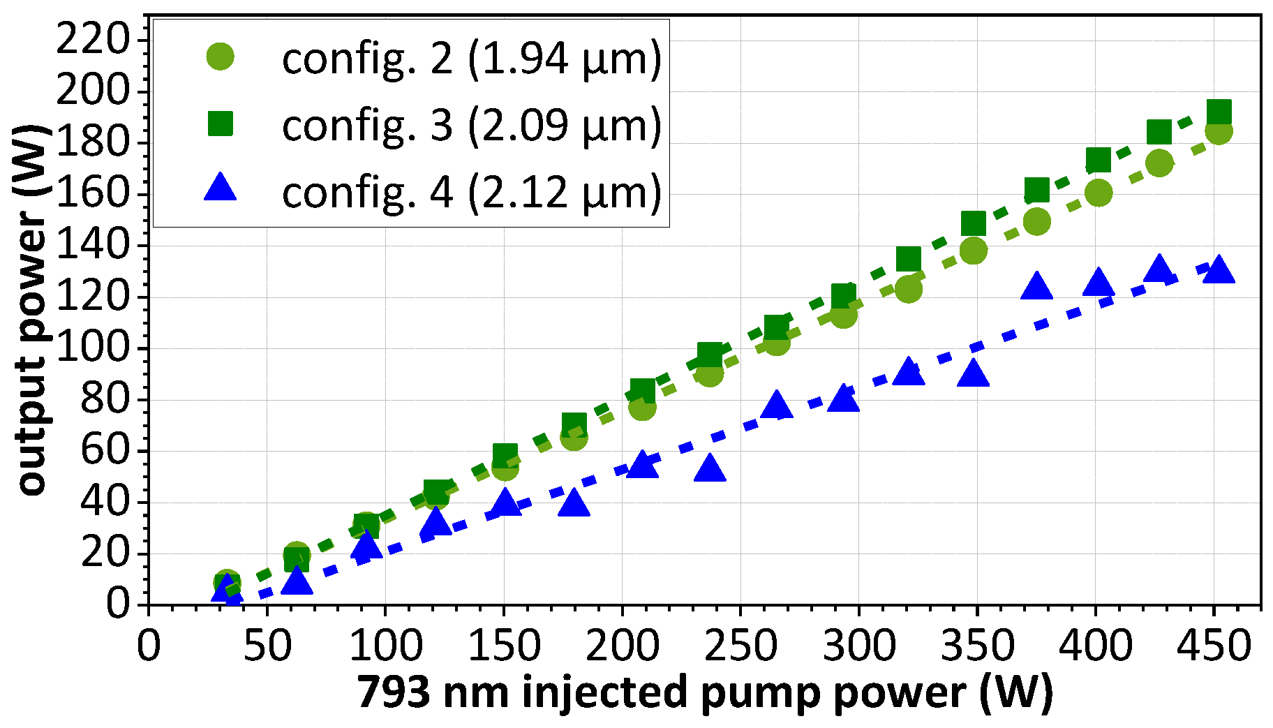
3.2. Output Power Evolution for Different FBG-Imposed Wavelengths

In the second experiment, we implemented the three aforementioned HR FBGs on the setup described in Figure 4: at a wavelength perfectly adapted to a thulium-doped laser (FBG #1940–configuration 2), and at two wavelengths commonly achieved by holmium ions (FBG #2090 at 2.09 µm–configuration 3 and FBG #2120 at 2.12 µm–configuration 4). The power evolution of these three configurations versus the injected 793 nm pump power is shown in Figure 10. The main output characteristics are condensed in Table 2.
At 1.94 µm, a maximum output power of 185 W and a slope efficiency of 42% were obtained. The FBG #2090 achieved a higher power and a higher slope efficiency, with 193 W and 45.6%, respectively. We can notice that the efficiency at 2.09 µm is particularly high, greater than the efficiency at 1.94 µm. The laser even operates at a slope efficiency exceeding the Stokes efficiency, defined as the λ pump / λ signal ratio (37.9% at 2.09 µm). This demonstrates a very efficient two-for-one cross relaxation process in the fiber. On the other side of the setup, we measured a maximum power transmitted by the FBG of 16 W in configuration 2 and 25 W in configuration 3. It indicates that around 8% of the total power is not reflected by the FBG #1940 and 11% by the FBG #2090. The two FBGs were designed to present a maximum reflectivity of 99%. The higher transmitted part of power was introduced by the part of power that was not propagating in the core of the FBG fiber but in its cladding. Indeed, there is a coupling between the pedestal of the active fiber and the cladding of the passive fiber, and the splice quality is one of the origins of this coupling [12,39]. A better splice quality of the FBG #1940 explains the lower coupling and thus the reduced transmitted power. This hypothesis is in agreement with the fiber geometries: the FBG #1940 fiber was adapted to the TDF whereas the mismatch of geometry between the TDF and the FBG #2090 fiber causes more coupling into the cladding. Finally, the perfectly linear evolution measured at 1.94 µm and 2.09 µm is not repeated in the fourth configuration (2.12 µm imposed by the FBG #2120). In this configuration, a more chaotic evolution of the output power was observed and limited the maximum output power to 130 W. The thulium ions of the 5-meter-long highly doped TDF seem not to allow achieving an efficient 2.12 µm emission.

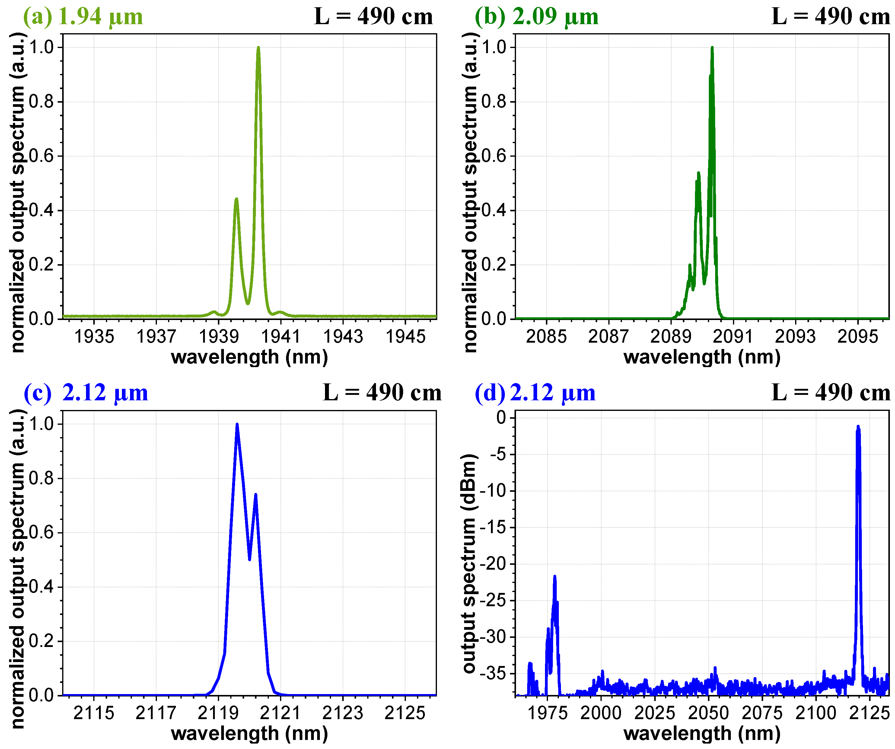
3.3. Output Spectra in the Three Imposed-Wavelength Configurations

For each configuration with L = 490 cm, the spectrum is shown on a 12-nanometer band around the FBG wavelength (Figure 11a–c). In configuration 2 with the FBG #1940 (Figure 11a ), the main peak of the output spectrum is centered at 1940.28 nm (full-width at half-maximum, FWHM = 0.24 nm). A second peak, 58% lower, is also visible on Figure 11a. It is centered at 1939.58 nm and 0.28 nm large. The shift between these two peaks is constant all over the power increase. The normalized output spectrum measured in configuration 3, shown on Figure 11b, exhibits a main peak at 2090.32 nm (FWHM = 0.18 nm). A second peak, 46% lower, is also noticeable at the left of the main peak, centered at 2089.88 nm (FWHM = 0.22 nm). We assume that this spectral shape of a double-peak at two very close wavelengths is due to the birefringence of a part of the fibers that composed the setup. Typically, even if the TDF and the associated passive fiber are no PM, boron stress rods exist on the PC2 fiber (panda type) as on the FBG #2090 and FBG #2120 fibers. The two neutral axes of this part of the cavity can explain the presence of these two peaks on the spectra.
The spectrum measured in the fourth configuration with the 2.12 µm FBG seems broader because the two peaks are relatively overlapped (Figure 11c). A main peak was measured at 2119.6 nm and a second peak was measured at 2120.0 nm at a comparable level. Furthermore, as shown in Figure 11d at 238 W of pump power, secondary peaks were measured all along the power scaling around 1.98 µm despite the 8°-cleaved angle that was used to avoid a parasitic cavity that can exist between the output coupler and the fiber cleave of the FBG. However, as the angle cleave does not eliminate Fresnel reflections at the interface (the angle makes the light being reflected out of the core), we suppose that in the case of an imposed wavelength that is too high for the piece of thulium-doped fiber under test, small reflections that still exist at this interface are sufficient to create a parasitic cavity implying clad propagation despite the angle cleave. Additionally, because of the simultaneous emissions at 1.98 µm and 2.12 µm that were not separated when measuring the output power, we can presume that the real part of the light emitted at 2.12 µm was lower than 130 W. By calculating the ratio of spectral power density between the main peak and the secondary emission on the different spectra measured in this configuration, we can assume that almost 80% of the light is emitted at 2.12 µm and a part of 20% is emitted at 1.98 µm. That represents 100 W of power converted to 2120 nm and a 793-to-2120 nm efficiency lower than 24% at this wavelength. According to the Stokes efficiency of 37.4% at 2.12 µm, it confirms that the laser source is not efficient at this wavelength in this configuration. The 2.12 µm wavelength is above the limit that can be supported by the 5-meter thulium-doped fiber. In other words, the laser finds another wavelength to emit at, despite the high reflectivity at 2.12 µm of the FBG. However, the results show that emission at such long wavelengths is possible and they are very encouraging that the efficiency can be optimized by defining a specifically highly doped fiber and the appropriate fiber length.

3.4. Shortening of the Thulium-Doped Fiber Length

The same power measurement was performed after reducing the TDF length to 3.6 m. This new fiber length corresponds to a maximum gain wavelength of around 2.00 µm. The resulting curves are depicted in Figure 12 and the main output characteristics are condensed in Table 3. In configuration 2’ (with the FBG #1940), a maximum output power of 191 W and a slope efficiency of 43.2% were obtained when L = 360 cm. Even if the 1.94 µm emission is still linear, the 2.09 µm emission in configuration 3’ (with the FBG #2090) also became perturbed. The maximum attainable output power at 2.09 µm decreased to 131 W (slope efficiency: 29.6%).
We recognize the same evolution as already observed in Figure 10 for the configuration 4 (FBG #2120 and L = 490 cm). This behavior is comparable to the nonlinear evolution of power observed when a parasitic second cavity is present in the experimental setup [39]. This new result confirms that the laser is unstable at higher wavelengths when the active fiber length is too short (3.6 m for 2.09 µm, 4.9 m for 2.12 µm). It implies that the ability to achieve a good efficiency at higher wavelengths depends both on the dopant concentration and on the fiber length.

4. Discussion

The results presented above, obtained with different cavity configurations, clearly demonstrate the possibility of laser operation at wavelengths exceeding 2.1 µm for an only-thulium-doped single-oscillator monolithic fiber laser. This is indeed a remarkable result, as typically these wavelengths can only be reached by thulium/holmium co-doped fiber lasers or by holmium-doped fiber lasers that need pumping by a thulium-doped laser, as demonstrated in Figure 2, in contrast to lasers around 1 µm [42], 1.5 µm [43] or even 2 µm [7], which can be directly pumped by commercially available diode lasers.
In the following, we discuss the importance of this contribution as a step forward to new possibilities for the generation of mid-infrared radiation in the range of 3 µm to 5 µm. This spectral region can be reached by quantum cascade lasers [44]. However, their output is limited to some watts. High-power mid-infrared sources are typically based on non-linear conversion using an OPO [45], Raman conversion in gas-filled hollow-core fibers [46], or by supercontinuum generation in fluoride fibers covering a big part of the spectral band of interest [47]. All these techniques require high-power pump sources around 2 µm. The OPO approach is particularly interesting using ZGP crystals as nonlinear conversion medium [48]. Pumping this crystal at 2.1 µm is more conveniant for high power, since its residual absorption is lower at 2.1 µm than at 2.0 µm, resulting in less heating and, therefore, a better laser efficiency. Furthermore, high-power lasers with a simple architecture are the best solution for OPO-pumping. Therefore, this contribution paves the way for a new generation of OPO-pumping sources based on a monolithic single-oscillator fiber-laser emitting at the desired wavelength. Moreover, our laser source uses an only thulium-doped fiber, which reduces the complexity relying on a much more mature fiber technology, and allows for direct diode pumping with commercially available laser diodes at 793 nm. In order to efficiently apply such laser sources for OPO-pumping, pulsed emission is mandatory, and the next step will be the development of an adapted pulsed laser source based on our approach, but this is, of course, outside of the scope of this work.
Besides mid-infrared conversion, 2 µm radiation is also directly relevant for many civil and military applications, including surgery [49,50,51], material processing [52,53], gas detection [54], and LIDAR [55,56]. For applications such as laser weapons, any wavelength around 2 µm could be used. However, in this case, the main requirements are high laser efficiency and good atmospheric transmission at the chosen wavelength. From Figure 13, which displays an example of an atmospheric transmission curve in specific geographic conditions, one can easily see that the spectral band between 1920 nm and 2050 nm is subject to many absorption peaks, leaving only few and very narrow transmission windows. But this spectral domain corresponds exactly to the emission band of traditional thulium-doped fiber lasers leaving wavelengths around 2040 nm, the only applicable possibility (highlighted by a red box in Figure 13). However, local geographic or climate conditions may induce spectral shift or broadening, thus limiting the potential use of such sources. The second part of the transmission curve, corresponding to wavelengths from 2074 nm to 2220 nm (limit of silica transmission) features clearly more and much broader transmission windows (blue box in Figure 13). Traditionally, this spectral domain is only achieved by holmium-doped laser sources. Therefore, the ability of thulium-doped fiber laser sources to emit at these wavelengths, as reported in this work, is very advantageous for air propagation over long distances.

5. Conclusions

In this paper, we studied the efficiencies that can be achieved using a thulium-doped fiber that exhibits a high 793 nm absorption of 8.42 dB/m at different wavelengths. A monolithic single-oscillator thulium-doped fiber laser source in which the cavity is formed by a 0°-cleaved angle output coupler and an FBG was developed. Three wavelengths imposed by three different FBGs were successively generated. At 1.94 µm, in the standard efficient emission band of thulium, the source exhibited 185 W of output power and a slope efficiency of 42.0% for an active fiber length of 5 m. At 2.09 µm, the emission was particularly efficient (45.6%) and achieved 193 W. However, when the fiber length was shortened to 3.6 m, the laser operation was impaired by a nonhomogeneous evolution of the output power as a function of the pump power. This behavior was identified as the signature of the presence of a parasitic emission that disturbs the main emission imposed by the FBG. Finally, a 2.12 µm FBG was implemented on the experimental setup, which allowed for demonstrating for the first time, to the best of our knowledge, high-power emission at longer wavelengths beyond 2.1 µm. However, some difficulties for the 5-meter piece of fiber to achieve this wavelength are present. We showed that longer fiber lengths are fostering emission at longer wavelengths and that efficient emission at higher wavelengths depends both on the dopant concentration and the active fiber length. Even more efficient and stable laser emission at wavelengths exceeding 2.1 µm might be possible with only thulium-doped fiber lasers choosing an appropriate fiber. This opens the door for new application such as direct pumping of an OPO which requires longer wavelengths than the typical output of thulium-doped fiber lasers.

Author Contributions

Conceptualization, C.L., N.D. and A.H.-D.; methodology, C.L., A.M., T.I., F.S. and A.B.; software, F.S.; validation, C.L., A.M., I.M.-H., N.D. and A.H.-D.; formal analysis, C.L., F.S., A.M., N.D., I.M.-H. and A.H.-D.; investigation, C.L., F.S., A.M., A.B. and T.I.; resources, T.R. and B.C.; data curation, C.L. and F.S.; writing—original draft preparation, C.L.; writing—review and editing, I.M.-H., A.M., A.B., N.D. and A.H.-D.; visualization, C.L.; supervision, A.H.-D.; project administration, A.H.-D.; funding acquisition, A.H.-D. All authors have read and agreed to the published version of the manuscript.

Funding

This work was supported by the French DGA (Direction Générale de l’Armement).

Institutional Review Board Statement

Not applicable.

Informed Consent Statement

Not applicable.

Data Availability Statement

Data underlying the results presented in this paper are not publicly available at this time but may be obtained from the authors upon reasonable request.

Conflicts of Interest

Authors Thierry Robin and Benoit Cadier were employed by the company Exail. The authors declare that the research was conducted in the absence of any commercial or financial relationships that could be construed as a potential conflict of interest.

References

  1. Jeong, Y.; Sahu, J.K.; Payne, D.N.; Nilsson, J. Ytterbium-doped large-core fiber laser with 1.36 kW continuous-wave output power. Opt. Express 2004, 12, 6088–6092. [Google Scholar] [CrossRef]
  2. Zellmer, H.; Willamowski, U.; Tünnermann, A.; Welling, H.; Unger, S.; Reichel, V.; Müller, H.-R.; Kirchhof, J.; Albers, P. High-power cw neodymium-doped fiber laser operating at 9.2 W with high beam quality. Opt. Lett. 1995, 20, 578–580. [Google Scholar] [CrossRef] [PubMed]
  3. Paschotta, R.; Nilsson, J.; Tropper, A.C.; Hanna, D.C. Ytterbium-doped fiber amplifiers. IEEE J. Quantum Electron. 1997, 33, 1049–1056. [Google Scholar] [CrossRef]
  4. Bellemare, A. Continuous-wave silica-based erbium-doped fibre lasers. Prog. Quantum Electron. 2003, 27, 211–266. [Google Scholar] [CrossRef]
  5. Yamashita, T.; Qin, G.; Suzuki, T.; Ohishi, Y. A New Green Fiber Laser using Terbium-doped Fluoride fiber. In Proceedings of the OFC/NFOEC 2008—2008 Conference on Optical Fiber Communication/National Fiber Optic Engineers Conference, San Diego, CA, USA, 24–28 February 2008. [Google Scholar] [CrossRef]
  6. Peterka, P.; Kasik, I.; Dhar, A.; Dussardier, B.; Blanc, W. Theoretical modeling of fiber laser at 810 nm based on thulium-doped silica fibers with enhanced 3H4 level lifetime. Opt. Express 2011, 19, 2773–2781. [Google Scholar] [CrossRef] [PubMed]
  7. Hemming, A.; Simakov, N.; Haub, J.; Carter, A. A review of recent progress in holmium-doped silica fibre sources. Opt. Fiber Technol. 2014, 20, 621–630. [Google Scholar] [CrossRef]
  8. Meleshkevich, M.; Platonov, N.; Gapontsev, D.; Drozhzhin, A.; Sergeev, V.; Gapontsev, V. 415 W Single-Mode CW Thulium Fiber Laser in all-fiber format. In Proceedings of the CLEO/Europe and IQEC 2007 Conference Digest, Munich, Germany, 17–22 June 2007. [Google Scholar] [CrossRef]
  9. Hemming, A.; Bennetts, S.; Davidson, A.; Carmody, N.; Lancaster, D.G. A 226W high power Tm fibre laser. In Proceedings of the OECC/ACOFT 2008—2008 Joint Conference of the Opto-Electronics and Communications Conference and the Australian Conference on Optical Fibre Technology, Sydney, NSW, Australia, 7–10 July 2008. [Google Scholar] [CrossRef]
  10. Moulton, P.F.; Rines, G.A.; Slobodtchikov, E.V.; Wall, K.F.; Frith, G.; Samson, B.; Carter, A.L.G. Tm-Doped Fiber Lasers: Fundamentals and Power Scaling. IEEE J. Sel. Top. Quantum Electron. 2009, 15, 85–92. [Google Scholar] [CrossRef]
  11. Tang, Y.; Huang, C.; Wang, S.; Li, H.; Xu, J. High-power narrow-bandwidth thulium fiber laser with an all-fiber cavity. Opt. Express 2012, 20, 17539–17544. [Google Scholar] [CrossRef]
  12. Simakov, N.; Hemming, A.V.; Carter, A.; Farley, K.; Davidson, A.; Carmody, N.; Hughes, M.; Daniel, J.M.O.; Corena, L.; Stepanov, D.; et al. Design and experimental demonstration of a large pedestal thulium-doped fibre. Opt. Express 2015, 23, 3126–3133. [Google Scholar] [CrossRef]
  13. Walbaum, T.; Heinzig, M.; Schreiber, T.; Eberhardt, R.; Tünnermann, A. Monolithic thulium fiber laser with 567 W output power at 1970 nm. Opt. Lett. 2016, 41, 2632–2635. [Google Scholar] [CrossRef]
  14. Ramírez-Martínez, N.J.; Núñez-Velázquez, M.; Umnikov, A.A.; Sahu, J.K. Highly efficient thulium-doped high-power laser fibers fabricated by MCVD. Opt. Express 2019, 27, 196–201. [Google Scholar] [CrossRef]
  15. Ehrenreich, T.; Leveille, R.; Majid, I.; Tankala, K. 1-kW, All-Glass Tm fiber Laser. In Proceedings of the SPIE Photonics West 2010: LASE, San Francisco, CA, USA, 23–28 January 2010. Conference 7580.
  16. Wang, X.; Zhou, P.; Wang, X.; Xiao, H.; Si, L. 102 W monolithic single frequency Tm-doped fiber MOPA. Opt. Express 2013, 21, 32386–32392. [Google Scholar] [CrossRef]
  17. Liu, J.; Shi, H.; Liu, K.; Hou, Y.; Wang, P. 210 W single-frequency, single-polarization, thulium-doped all-fiber MOPA. Opt. Express 2014, 22, 13572–13578. [Google Scholar] [CrossRef]
  18. Wang, X.; Jin, X.; Zhou, P.; Wang, X.; Xiao, H.; Liu, Z. High power, widely tunable, narrowband superfluorescent source at 2 µm based on a monolithic Tm-doped fiber amplifier. Opt. Express 2015, 23, 3382–3389. [Google Scholar] [CrossRef] [PubMed]
  19. Shah, L.; Sims, R.A.; Kadwani, P.; Willis, C.C.; Bradford, J.B.; Sincore, A.; Richardson, M. High-power spectral beam combining of linearly polarized Tm:fiber lasers. Appl. Opt. 2015, 54, 757–762. [Google Scholar] [CrossRef] [PubMed]
  20. Yin, K.; Zhu, R.; Zhang, B.; Liu, G.; Zhou, P.; Hou, J. 300 W-level, wavelength-widely-tunable, all-fiber integrated thulium-doped fiber laser. Opt. Express 2016, 24, 11085–11090. [Google Scholar] [CrossRef] [PubMed]
  21. Goodno, G.D.; Book, L.D.; Rothenberg, J.E. Low-phase-noise, single-frequency, single-mode 608 W thulium fiber amplifier. Opt. Lett. 2009, 34, 1204–1206. [Google Scholar] [CrossRef]
  22. Yao, W.; Shen, C.; Shao, Z.; Wang, J.; Wang, F.; Zhao, Y.; Shen, D. 790 W incoherent beam combination of a Tm-doped fiber laser at 1941 nm using a 3 × 1 signal combiner. Syst. Control Lett. 2018, 57, 5574–5577. [Google Scholar] [CrossRef] [PubMed]
  23. Liu, Y.; Li, H.; Yang, L.; Dai, N.; Li, J.; Cao, C.; Xing, Y.; Liao, L.; Cao, R.; Zhang, F.; et al. 406 W Narrow-Linewidth All-Fiber Amplifier With Tm-Doped Fiber Fabricated by MCVD. IEEE Photon. Technol. Lett. 2019, 31, 1779–1782. [Google Scholar] [CrossRef]
  24. Liu, Y.Z.; Xing, Y.B.; Liao, L.; Wang, Y.B.; Peng, J.G.; Li, H.Q.; Dai, N.L.; Li, J.Y. 530 W all-fiber continuous-wave Tm-doped fiber laser. Acta Phys. Sin. 2019, 69, 184209. [Google Scholar] [CrossRef]
  25. Shin, J.S.; Cha, Y.H.; Chun, B.J.; Jeong, D.Y.; Park, H. 200-W Continuous-wave Thulium-doped All-fiber Laser at 2050 nm. Curr. Opt. Photonics 2021, 4, 306–310. [Google Scholar] [CrossRef]
  26. Anderson, B.M.; Soloman, J.; Flores, A. 1.1 kW, beam-combinable thulium doped all-fiber amplifier. In Proceedings of the SPIE Photonics West 2021: LASE, San Francisco, CA, USA, 6–11 March 2021. Proceedings SPIE 11665. [Google Scholar] [CrossRef]
  27. Romano, C.; Panitzek, D.; Lorenz, D.; Forster, P.; Eichhorn, M.; Kieleck, C. High-Power Thulium-Doped Fiber MOPA Emitting at 2036 nm. J. Light. Technol. 2024, 42, 394–398. [Google Scholar] [CrossRef]
  28. Michalska, M.; Honzatko, P.; Grzes, P.; Kamradek, M.; Podrazky, O.; Kasik, I.; Swiderski, J. Thulium-Doped 1940- and 2034-nm Fiber Amplifiers: Towards Highly Efficient, High-Power All-Fiber Laser Systems. J. Light. Technol. 2024, 42, 339–346. [Google Scholar] [CrossRef]
  29. Ren, C.; Shen, Y.; Zheng, Y.; Mao, Y.; Wang, F.; Shen, D.; Zhu, H. Widely-tunable all-fiber Tm doped MOPA with >1 kW of output power. Opt. Express 2023, 31, 22733–22739. [Google Scholar] [CrossRef] [PubMed]
  30. Hemming, A.; Simakov, N.; Davidson, A.; Oermann, M.; Corena, L.; Stepanov, D.; Carmody, N.; Haub, J.; Swain, R.; Carter, A. Development of high-power holmium-doped fibre amplifiers. In Proceedings of the SPIE Photonics West 2014: LASE, San Francisco, CA, USA, 1–6 February 2014. Proceedings SPIE 8961. [Google Scholar] [CrossRef]
  31. Hemming, A.; Simakov, N.; Davidson, A.; Bennetts, S.; Hughes, M.; Carmody, N.; Davies, P.; Corena, L.; Stepanov, D.; Haub, J.; et al. A monolithic cladding pumped holmium-doped fibre laser. In Proceedings of the 2013 Conference on Lasers and Electro-Opics, San Jose, CA, USA, 9–14 June 2013. [Google Scholar] [CrossRef]
  32. Hemming, A.; Bennetts, S.; Simakov, N.; Davidson, A.; Haub, J.; Carter, A. High power operation of cladding pumped holmium-doped silica fibre lasers. Opt. Express 2013, 21, 4560–4566. [Google Scholar] [CrossRef]
  33. Le Gouët, J.; Gustave, F.; Bourdon, P.; Robin, T.; Laurent, A.; Cadier, B. Realization and simulation of high-power holmium doped fiber lasers for long-range transmission. Opt. Express 2020, 28, 22307–22320. [Google Scholar] [CrossRef]
  34. Beaumont, B.; Bourdon, P.; Barnini, A.; Kervella, L.; Robin, T.; Le Gouët, J. High efficiency holmium-doped triple-clad fiber laser at 2120 nm. J. Light. Tehchnol. 2022, 40, 6480–6485. [Google Scholar] [CrossRef]
  35. Ramírez-Martínez, N.J.; Núñez-Velázquez, M.; Sahu, J.K. Study on the dopant concentration ratio in thulium-holmium doped silica fibers for lasing at 2.1 µm. Opt. Express 2020, 28, 24961–24967. [Google Scholar] [CrossRef]
  36. Jackson, S.; Sabella, A.; Hemming, A.; Bennetts, S.; Lancaster, D. High-Power 83 W Holmium-Doped Silica Fiber Laser Operating with High Beam Quality. Opt. Lett. 2007, 32, 241–243. [Google Scholar] [CrossRef] [PubMed]
  37. Dalloz, N.; Robin, T.; Cadier, B.; Kieleck, C.; Eichhorn, M.; Hildenbrand-Dhollande, A. 55 W actively Q-switched single oscillator Tm3+, Ho3+-codoped silica polarization maintaining 2.09 µm fiber laser. Opt. Express 2019, 27, 8387–8394. [Google Scholar] [CrossRef]
  38. Forster, P.; Romano, C.; Kieleck, C.; Eichhorn, M. Advances in two-micron lasers for nonlinear conversion into the mid-IR. In Proceedings of the SPIE Photonics Europe, Online, 6–10 April 2020. Proceedings SPIE 11355. [Google Scholar] [CrossRef]
  39. Motard, A.; Louot, C.; Robin, T.; Cadier, B.; Manek-Hönninger, I.; Dalloz, N.; Hildenbrand-Dhollande, A. Diffraction limited 195-W continuous wave laser emission at 2.09 µm from a Tm3+, Ho3+-codoped single-oscillator monolithic fiber laser. Opt. Express 2021, 29, 6599–6607. [Google Scholar] [CrossRef] [PubMed]
  40. Forster, P.; Romano, C.; Schneider, J.; Eichhorn, M.; Kieleck, C. High-power continuous-wave Tm3+:Ho3+-codoped fiber laser operation from 2.1 µm to 2.2 µm. Opt. Lett. 2022, 47, 2542–2545. [Google Scholar] [CrossRef] [PubMed]
  41. Motard, A.; Louot, C.; Manek-Hönninger, I.; Dalloz, N.; Hildenbrand-Dhollande, A. Optimizing the Performance of a Monolithic Tm3+, Ho3+-Codoped Fiber Laser by FBG reflected wavelength and Fiber Gain Matching. Opt. Express 2023, 31, 18939–18948. [Google Scholar] [CrossRef] [PubMed]
  42. Zervas, M.N.; Codemard, C.A. High Power Fiber Lasers: A Review. IEEE J. Sel. Top. Quantum Electron. 2014, 20, 0904123. [Google Scholar] [CrossRef]
  43. Wang, Z.; Zhang, B.; Liu, J.; Song, Y.; Zhang, H. Recent developments in mid-infrared fiber lasers: Status and challenges. Opt. Laser Technol. 2020, 132, 106497. [Google Scholar] [CrossRef]
  44. Mawst, L.J.; Botez, D. High-Power Mid-Infrared (λ∼3–6 µm) Quantum Cascade Lasers. IEEE Photonics J. 2022, 14, 1–25. [Google Scholar] [CrossRef]
  45. Medina, M.A.; Piotrowski, M.; Schellhorn, M.; Wagner, F.R.; Berrou, A.; Hildenbrand-Dhollande, A. Beam quality and efficiency of ns-pulsed high-power mid-IR ZGP OPOs compared in linear and non-planar ring resonators. Opt. Express 2021, 29, 21727–21737. [Google Scholar] [CrossRef]
  46. Gladyshev, A.V.; Kosolapov, A.F.; Khudyakov, M.M.; Yatsenko, Y.P.; Kolyadin, A.N.; Krylov, A.A.; Pryamikov, A.D.; Biriukov, A.S.; Likhachev, M.E.; Bufetov, I.A. 4.4-µm Raman laser based on hollow-core silica fibre. Quantum Electron. 2017, 47, 491. [Google Scholar] [CrossRef]
  47. Scurria, G.; Manek-Hönninger, I.; Carré, J.Y.; Hildenbrand-Dhollande, A.; Bigotta, S. 7 W mid-infrared supercontinuum generation up to 4.7 µm in an indium-fluoride optical fiber pumped by a high-peak power thulium-doped fiber single-oscillator. Opt. Express 2020, 28, 7672–7677. [Google Scholar] [CrossRef]
  48. Piotrowski, M.; Medina, M.A.; Schellhorn, M.; Spindler, G.; Hildenbrand-Dhollande, A. Effects of pump pulse energy and repetition rate on beam quality in a high-power mid-infrared ZnGeP2 OPO. Opt. Express 2021, 29, 2577–2586. [Google Scholar] [CrossRef] [PubMed]
  49. Fried, N.M.; Murray, K.E. High-power thulium fiber laser ablation of urinary tissues at 1.94 µm. J. Endourol. 2005, 19, 25–31. [Google Scholar] [CrossRef]
  50. Fried, N.M. High-power laser vaporization of the cani-neprostate using a 110W Thulium fiber laser at 1.91 µm. Lasers Surg. Med. 2005, 36, 52–56. [Google Scholar] [CrossRef]
  51. Warnaby, C.E.; Coleman, D.J.; King, T.A. Photothermal modelling of thulium fibre laser-tissue interactions. In Proceedings of the European Conference on Biomedical Optics 2003: Therapeutic Laser Applications and Laser-Tissue Interactions 2003, Munich, Germany, 24–25 June 2003. Proceedings SPIE 5142-68. [Google Scholar] [CrossRef]
  52. Zhu, X.; Jiang, S. 2 µm Fiber Laser Enable Versatile Processing of Plastics. Ind. Laser Solut. Manuf. 2016, 31, 18–23. [Google Scholar]
  53. Mingareev, I.; Weirauch, F.; Olowinsky, A.; Shah, L.; Kadwani, P.; Richardson, M. Welding of polymers using a 2 µm thulium fiber laser. Opt. Laser Technol. 2012, 44, 2095–2099. [Google Scholar] [CrossRef]
  54. Barrientos Barria, J.; Mammez, D.; Cadiou, E.; Dherbecourt, J.B.; Raybaut, M.; Schmid, T.; Bresson, A.; Melkonian, J.M.; Godard, A.; Pelon, J.; et al. Multispecies high-energy emitter for CO2, CH4, and H2O monitoring in the 2 µm range. Opt. Lett. 2014, 39, 6719–6722. [Google Scholar] [CrossRef] [PubMed]
  55. Koch, G.J.; Beyon, J.Y.; Petzar, P.E.; Petros, M.; Yu, J.; Trieu, B.C.; Kavaya, M.J.; Singh, U.N.; Modlin, E.A.; Barnes, B.W.; et al. Field testing of a high-energy 2 µm Doppler LIDAR. J. Appl. Remote Sens. 2010, 4, 043512. [Google Scholar] [CrossRef]
  56. Koch, G.J.; Beyon, J.Y.; Barnes, B.W.; Petros, M.; Yu, J.; Amzajerdian, F.; Kavaya, M.J.; Singh, U.N. High-energy 2 µm doppler lidar for wind measurements. Opt. Eng. 2007, 46, 116201. [Google Scholar] [CrossRef]
Figure 1. (a) Radiative transitions relevant for 2 µm thulium-doped fiber lasers with common pump bands highlighted in blue; (b) ion–ion energy transfer processes.
Photonics 11 00246 g001
Figure 2. Comparison of the maximum output power of 2 µm fiber lasers in continuous wave regime demonstrated in the literature, as a function of their emission wavelength. On blue background: Tm   3 + doping. On green background: Tm   3 + , Ho   3 + co-doping or Ho   3 + doping. Both the slope efficiency and the corresponding bibliographic reference are labeled for each point.
Photonics 11 00246 g002
Figure 3. Measurement of the laser power at the output of an oscillating cavity made with a Tm   3 + doped fiber (green) or a Tm   3 + , Ho   3 + -codoped fiber (blue), depending on the emission wavelength and the length of doped fiber. The emission wavelength was selected by changing the angle of a diffraction grating positioned at one end of the cavity (maximum reflectivity). The other end of the cavity (output coupler) consisted of the active fiber cleaved at 0° (4% of Fresnel reflection).
Photonics 11 00246 g003
Figure 4. Schematic representation of the experimental setup for the monolithic single-oscillator thulium-doped fiber laser source. Fiber fusion splices are represented by red dots. FBG: fiber Bragg grating; HR: high reflectivity; OC: output coupler; PC: pump combiner; TDF: thulium-doped fiber.
Photonics 11 00246 g004
Figure 5. Microscope image of the thulium-doped fiber developed by exail/iXblue Photonics.
Photonics 11 00246 g005
Figure 6. Reflectivity spectra of the FBG #1940, the FBG #2090 and the FBG #2120.
Photonics 11 00246 g006
Figure 7. Schematic representation of the experimental setup in free-running configuration (Fresnel cavity), without FBG.
Photonics 11 00246 g007
Figure 8. Measured power (a) and low-power spectrum (b) at the output of the setup described in Figure 7. L = 490 cm. Resolution: 0.01 nm. The dashed line is the numerical fit used to calculate both the slope efficiency and the threshold power.
Photonics 11 00246 g008
Figure 9. Emitted wavelength at the laser threshold at OC-1 versus the TDF length (pump power lower than 8 W). Resolution: 0.02 nm. Inset: schematic representation of the ASE-measurement setup.
Photonics 11 00246 g009
Figure 10. Output power evolution in configuration 2 (1.94 µm), in configuration 3 (2.09 µm) and in configuration 4 (2.12 µm) with a 490 cm long piece of TDF. The dashed lines are the linear fits used to calculate both the slope efficiency and the threshold power.
Photonics 11 00246 g010
Figure 11. Measured output spectrum at maximum output power in the three different configurations of imposed wavelengths on a 12 nm band: (a) 1.94 µm FBG. Resolution: 0.02 nm; (b) 2.09 µm FBG. Resolution: 0.02 nm; (c) 2.12 µm FBG. Resolution: 0.2 nm. TDF fiber length L = 490 cm; (d) Spectrum measured on a large span with the 2.12 µm FBG at 238 W of pump power (resolution: 0.2 nm).
Photonics 11 00246 g011
Figure 12. Output power evolution measured at the output of the thulium doped fiber in configuration 2’ (1.94 µm) and in configuration 3’ (2.09 µm) with a 360 cm long piece of thulium-doped fiber. The dashed lines are the numerical fits used to calculate both the slope efficiency and the threshold power.
Photonics 11 00246 g012
Figure 13. Example of atmospheric transmission curve at 1 km, in winter conditions with no humidity. Two atmospheric transmission windows are highlighted, 2034–2050 nm (in red) and 2074–2220 nm (in blue).
Photonics 11 00246 g013
Table 1. Description of the cavity configurations of the source in the four studied configurations.
Config.1234
FBGNone#1940#2090#2120
Reflectivity (%)4999999
Central wavelength (nm)-1939.382090.602120.0
FWHM bandwidth (nm)-2.921.261.27
Fiber typePAS 20/250PAS 20/250PAS PM 20/300PAS PM 20/300
Fiber NA0.110.110.080.08
End cleave
Table 2. Main output characteristics measured at the output of the source based on the use of a 490 cm long piece of TDF, working in configurations 2, 3, and 4, as defined in Table 1.
Config.234
FBG#1940#2090#2120
Maximum output power (W)185193132
Slope efficiency (%)42.045.622.8
Power threshold (W)19.922.834.6
Table 3. Main output characteristics measured at the output of the source based on the use of a 360 cm long piece of TDF, working in configurations 2’ and 3’.
Config.2’3’
FBG#1940#2090
Maximum output power (W)191131
Slope efficiency (%)43.229.6
Power threshold (W)19.712.8
Disclaimer/Publisher’s Note: The statements, opinions and data contained in all publications are solely those of the individual author(s) and contributor(s) and not of MDPI and/or the editor(s). MDPI and/or the editor(s) disclaim responsibility for any injury to people or property resulting from any ideas, methods, instructions or products referred to in the content.

