1. Introduction
Salmonella is a dangerous bacterial infection that can cause serious illness and even death, particularly for vulnerable populations such as young children, the elderly, and those with weakened immune systems. According to a report by the World Health Organization (WHO) in 2023, salmonella is estimated to cause around 155,000 deaths worldwide every year. In the United States alone, it is estimated to cause around 420 deaths and 26,500 hospitalizations annually [
1]. These statistics underscore the need for effective methods of detecting Salmonella contamination in food, water, and other environments to prevent the spread of infection and protect public health. A Bragg grating optical sensor, which is an optical device capable of quickly and accurately detecting the presence of salmonella, could serve as a valuable tool in preventing outbreaks of the disease. By enabling early identification of contaminated food or water, such a sensor would allow for prompt action to be taken to prevent the spread of infection. This technology could find applications in food production facilities, restaurants, and other settings where salmonella contamination is a risk, contributing to the protection of public health and the prevention of this dangerous infection. In some works, the Bragg grating sensor has been used to detect a tiny change in the refractive index [
2,
3,
4]; however, in their work, they use infrared light, which will lead to high loss when used with a water solution, unlike the proposed sensor, where visible light has been used.
The ion exchange technique is a process that involves creating a variation in the refractive index within the waveguide core. By controlling the ion doping pattern, it is possible to create a waveguide that can guide and manipulate light in a variety of ways. Ion exchange waveguides offer high optical quality, low loss, and high reliability, making them ideal for use in telecommunications, sensing, and other applications that require high precision and accuracy. They can also be easily integrated with other components, such as lasers and detectors, making them versatile tools for a wide range of applications. The ion exchange process allows for precise control over various parameters, such as diffusion time and heating duration during the initial diffusion stage, as well as the conditions governing light propagation. These controllable factors in the technological process play a pivotal role in determining the modal properties of gradient-index waveguides, which, in turn, significantly influence the operational characteristics of differential interferometers utilized in sensing applications [
5]. Our sensor utilizes the ion exchange process in conjunction with the Bragg grating to create an ultra-sensitive sensor. The ion exchange technique enables the formation of a high-quality waveguide, while the Bragg grating enhances the sensor’s sensitivity to detect and measure specific parameters. Together, these components contribute to the precision, reliability, and versatility of the sensor, making it an essential tool for a wide range of optical applications.
Ion exchange (IE) is a technique for producing optical waveguides by altering the optical properties of a solid material, typically a glass substrate. The process involves replacing some of the cations, mainly Na
+, near the surface of the glass with different monovalent cations such as K
+, Li
+, Rb
+, Cs
+, Tl
+, or Ag
+ [
6]. The ion exchange is facilitated by either heat diffusion or an electric field. The changes in the electrical permittivity, stress distribution, and light absorption of the glass depend on the concentration of the dopant cations. The ion exchange process can be precisely controlled by masking some parts of the glass surface, which enables the fabrication of customized components for various applications. The advancement of ion exchange technology has been accompanied by the development of theoretical modeling tools, which are essential for the design and creation of many devices. In particular, in the field of integrated optics, factors such as fiber compatibility and coupling losses are influenced by the spatial permittivity distribution, which is determined by the cation concentration [
7].
There are many ways of performing ion exchange fabrication, including electro-diffusion of multivalent metals, glass poling, and formation/dissolution of silver nanoparticles [
7]. A common technique for waveguide fabrication is ion exchange, which consists of one to three sequential steps depending on the desired outcome. The different configurations for potassium–sodium ion exchange are as follows. The first four configurations are used to insert ions into the glass substrate. The thermal ion exchange method, which inserts ions into the glass from a molten salt source using a patterned mask, is widely used [
8]. The field-assisted ion exchange method, which drives ions into the glass from a molten salt source at the anode side, is another option [
9]. The field-assisted ion exchange method, which supplies ions to the glass from a thin metal film source, is also possible. The thin film can be either placed over a patterned mask or directly patterned on the glass surface [
10]. The field-assisted ion exchange method, which combines a patterned metal film with a molten salt source at the anode side, can be used as a one-step method to produce buried waveguides. When the metal film source is exhausted, the process continues as a field-assisted burial, similar to another configuration [
11]. The last three configurations are used to adjust the existing ion concentration in the glass, allowing the modification of waveguide properties. These configurations are usually used as a second step in two-step fabrication processes. A simple thermal annealing process, which redistributes ions in the glass by diffusion, is one example [
12]. A thermal burial process, which pushes the original ions in the glass back to the substrate surface, while the ions forming the waveguide diffuse further into the material, is another example [
13]. Finally, a field-assisted burial process, wherein the original ions are reintroduced [
14].
Fiber Bragg gratings (FBG) are optical devices that consist of a periodic variation in the refractive index of an optical fiber core [
2]. This variation acts as a selective mirror that reflects light of a certain wavelength, known as the Bragg wavelength, and transmits the rest. The Bragg wavelength depends on the period and the average refractive index of the grating, according to the Bragg condition. When the Bragg grating is exposed to a medium with a different refractive index, the Bragg wavelength shifts due to the change in the effective refractive index of the grating. This shift in wavelength is directly proportional to the change in refractive index and can be used to measure the refractive index of the surrounding medium. The sensitivity of a Bragg grating refractive index sensor is defined as the ratio of the wavelength shift to the refractive index change, and it depends on several factors, such as the length of the grating, the strength of the grating, and the wavelength of the light used to probe the grating. Generally, longer gratings and stronger gratings have higher sensitivity, as they reflect lighter and produce a sharper spectral response [
2,
4]. Moreover, using light with a shorter wavelength can increase sensitivity, as the Bragg condition is more sensitive to refractive index changes at shorter wavelengths. However, this can also make the sensor more vulnerable to environmental noise, such as temperature fluctuations and mechanical strain. Bragg grating refractive index sensors have several advantages over other types of optical sensors. One advantage is their high sensitivity, which can enable the detection of very small changes in refractive index, in the order of
or less. Another advantage is their high resolution, which can allow for precise measurement of refractive index changes over a small range, typically less than 0.01. Furthermore, Bragg grating sensors can operate at high temperatures and in harsh environments, making them suitable for a range of industrial and scientific applications. Bragg grating refractive index sensors are used in various fields, such as chemical sensing, biological sensing, medical diagnostics, and environmental monitoring. For instance, they can be used to detect the presence of specific molecules in a fluid, by coating the grating with a functional layer that binds to the target molecules and alters the refractive index of the grating. They can also be used to monitor changes in the refractive index of blood, by inserting the grating into a blood vessel and measuring the wavelength shift caused by the blood flow. Moreover, they can be used to measure the concentration of pollutants in water, by calibrating the wavelength shift with the known refractive index of different water samples.
Moreover, the Bragg grating sensor shows many advantages in refractive index sensing applications. One of the advantages is the thermal stability of the Bragg grating sensor, which is a fundamental attribute that engenders trustworthiness and precision in measurements. Extensive studies have elucidated that the wavelength shift discrepancy between the reflection peaks and the core mode remains remarkably consistent, even in the face of temperature variations, thereby manifesting an insignificantly low-temperature cross-sensitivity. Empirical investigations have substantiated that both the cladding mode and the core mode exhibit analogous temperature sensitivities, thereby enabling refractive index (RI) measurements that remain unaffected by temperature fluctuations. This finding underscores the capability of the Bragg grating sensor to deliver temperature-independent RI measurements, thereby fortifying its reliability and accuracy in diverse operating conditions [
3,
15]. The sensor system and measuring method exhibit inherent capabilities for concurrent measurement of both temperature and refractive index, or for conducting refractometric measurements that demonstrate remarkable insensitivity to variations in temperature [
16]. biocompatibility, streamlined fabrication procedures, and adjustable optical, thermal, and mechanical properties. Notably, the induced modifications in the refractive index demonstrate exceptional stability even after prolonged thermal aging and extended storage, without any discernible degradation [
17]. These compelling findings underscore the robustness and reliability of the epoxy-based Bragg grating sensor, rendering it highly suitable for a wide range of practical applications.
A study showed that the concentration of salmonella solution with 1 mg/mL existed in contaminated drinking water, demonstrating a refractive index of 1.33133 [
18]. Conversely, the baseline solution that consists of drinking water at temperature of 37 °C has a refractive index of 1.3320 [
19]. According to these studies, the objective of this study is to propose a highly sensitive sensor that combines ion exchange (FBG) techniques to detect small refractive index changes, specifically with a magnitude of Δn = 0.001.
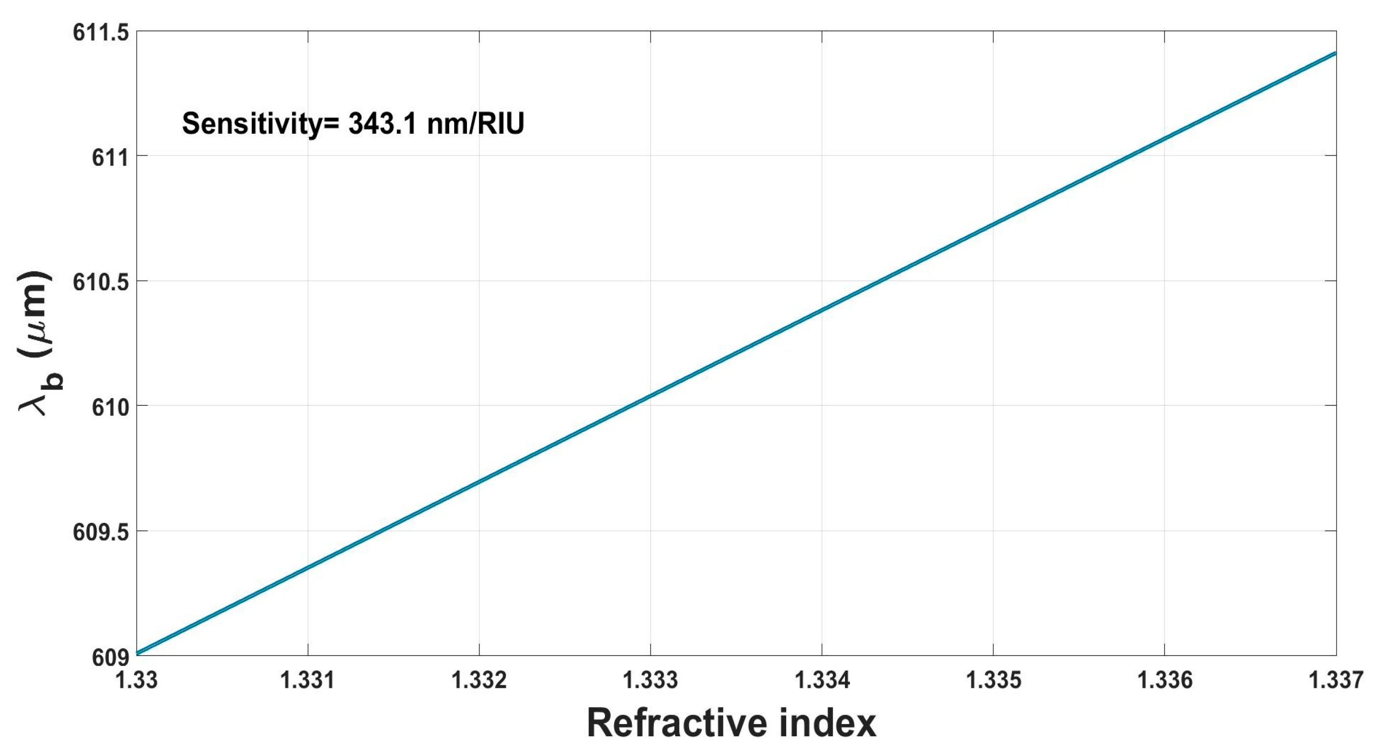
This research presents a novel optical sensing system that employs ion exchange technology and a phase-shifted Bragg grating design to measure refractive index changes. The sensor geometry was optimized using a finite difference time domain solver to achieve maximum sensitivity and figure of merit (FOM). The proposed design outperforms existing sensors in terms of responsiveness to refractive index variations and fabrication costs. The ion exchange process allows for precise control of the refractive index profile along the waveguide, which enhances the sensor’s sensitivity and FOM. The sensor consists of a graded-index waveguide and a phase-shifted Bragg grating, which are both fabricated by ion exchange. The phase-shifted Bragg grating introduces a narrow transmission peak within the reflection spectrum, which shifts according to the refractive index of the surrounding medium. The graded-index waveguide increases the interaction between the guided mode and the medium, which improves the sensitivity. The proposed sensor was tested for water-based sensing applications and achieved a FOM of 227.63 and a sensitivity of 343.1 nm/RIU, surpassing other Bragg grating sensors. The sensor can be used for various applications, such as environmental monitoring, chemical analysis, and biomedical sensing. Its high sensitivity, versatility, and portability make it suitable for field applications. In summary, the proposed on-chip optical sensing system demonstrates a significant improvement in refractive index sensing technology, and its high sensitivity and low fabrication costs make it a promising technology for sensing and monitoring applications in the future.
2. Sensor Structure and Ion Exchange Technique
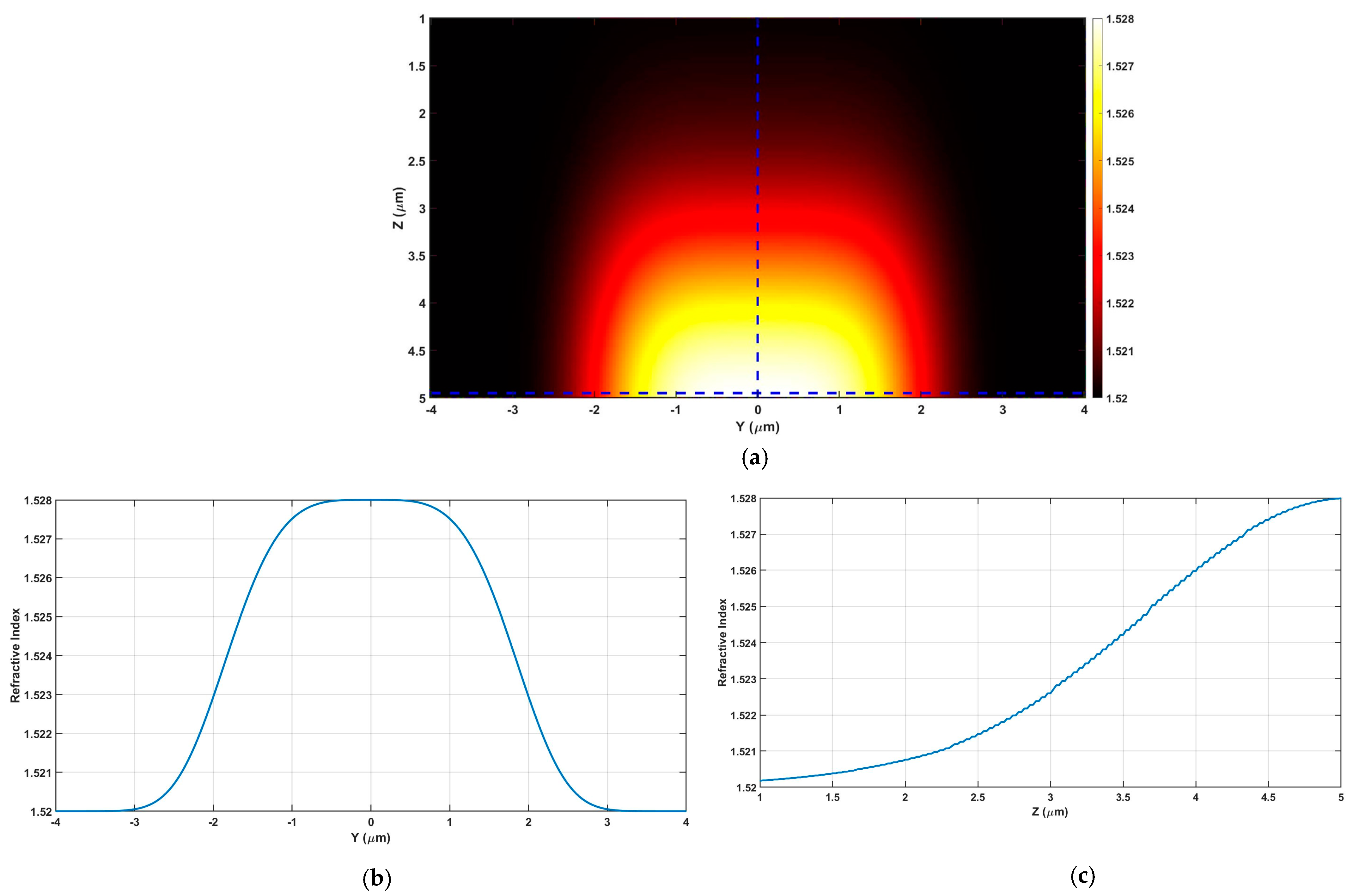
In the work of this investigation, a systematic application of the ion exchange technique was undertaken to fabricate periodic waveguides, with the primary objective of establishing graded index structures on glass. The mathematical representation of the graded index function, denoted as Equation (1), played a foundational role in this research endeavor. To impart meticulous control over the core width in the design, a mask was introduced. For a comprehensive visual exposition,
Figure 1a–c is presented, offering cross-sectional views of the graded index structures in both two and one dimensions. It is noteworthy that this fabrication technique affords several distinct advantages, encompassing cost-effectiveness, ease of implementation, and minimal coupling loss with optical fibers. These attributes collectively contribute to the viability and desirability of the proposed sensor design within the realm of optical waveguide technology.
The envisaged grating structure is meticulously fashioned upon a
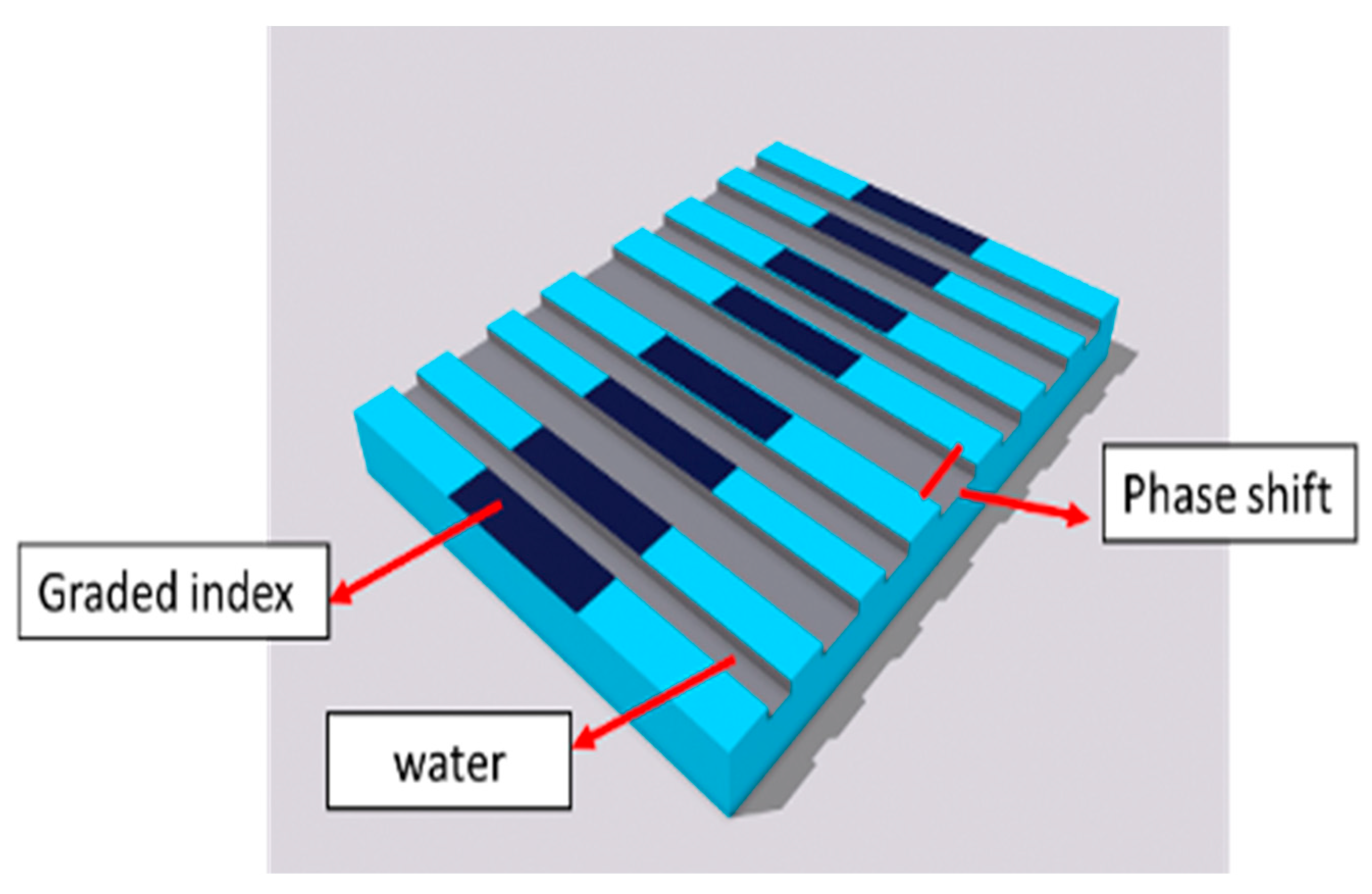
substrate, incorporating ion exchange periodic waveguides, with water serving as the designated cladding material. Previous investigations into water-based sensors utilizing infrared light revealed a notable power loss. Consequently, this design strategically embraces visible light to discern alterations in water-based solutions, thereby seeking to optimize performance and efficiency through the judicious application of the Bragg grating wavelength. The fabrication procedure entails the utilization of a graded index core achieved via ion exchange. To augment sensitivity, the core undergoes precision etching to conform to the prescribed graded profile. This etching process, depicted in
Figure 2, entails the application of a mask and laser, with the width precisely calibrated at half of the period Λ. The determination of Λ is derived from the Bragg grating Equation (2), with the substitution of
as 633 nm. Concurrently, the effective refractive index, denoted as
, is meticulously computed through finite-difference time-domain (FDTD) simulations. The resulting structure features slots created through the etching process facilitate the unhindered flow of the cladding solution. This deliberate augmentation of interaction between the mode profile and the solution yields heightened sensitivity. Experimental scrutiny discerned marginal alterations in the effective index, prompting a strategic introduction of a phase shift encompassing precisely half of the total number of periods. Simulation findings, corroborating this introduced modification, attest to a conspicuous enhancement in the effective index. Consequently, the finalized design integrates a graded index core distinguished by etching with phase shifts, as visually represented in
Figure 2. This three-dimensional schematic elucidates the intricacies of the proposed phase-shifted Bragg grating, uniquely tailored for the discernment of changes in water-based solutions.
The Bregg grating wavelength could be calculated as [
15,
19]:
Equation (2) controls the Bragg grating sensor; however, there are more factors or parameters that need to be considered while building the sensor such as grating period, grating length, and number of grating pitches. The grating period, denoting the spatial separation between consecutive alterations in the refractive index within the Bragg grating structure, is a crucial parameter with well-documented implications for the sensing performance of phase shift Bragg gratings. A diminished grating period induces a narrower reflection bandwidth, thereby facilitating sensing with heightened resolution. Nonetheless, this reduction in grating period also engenders augmented intricacy in fabrication procedures and heightened vulnerability to environmental factors such as temperature and strain. Conversely, a greater grating period yields a broader reflection bandwidth, rendering it suitable for sensing applications necessitating an expansive dynamic range. Phase shift refractive index modulation is a pivotal parameter that exerts a profound influence on the efficacy of phase shift Bragg gratings. The introduction of a phase shift within the grating structure engenders an amplified capacity for sensor sensitivity and selectivity. This augmentation enables the formulation of intricate spectral responses and the mitigation of undesired modes. The impact of phase shift refractive index modulation has been subject to extensive investigation, revealing its capacity to enhance the resolution and precision of sensing applications. The grating length pertains to the spatial span of the Bragg grating along the waveguide and assumes a pivotal role in dictating the reflection bandwidth and sensitivity of the phase shift Bragg grating sensor. An elongated grating length engenders an expanded interaction length between the guided light and the grating structure, thereby yielding augmented reflectivity and sensitivity. However, prolonged gratings may concurrently introduce escalated insertion losses and heightened susceptibilities to fabrication imperfections.
3. Optimizing the Number of Periods and the Sensitivity
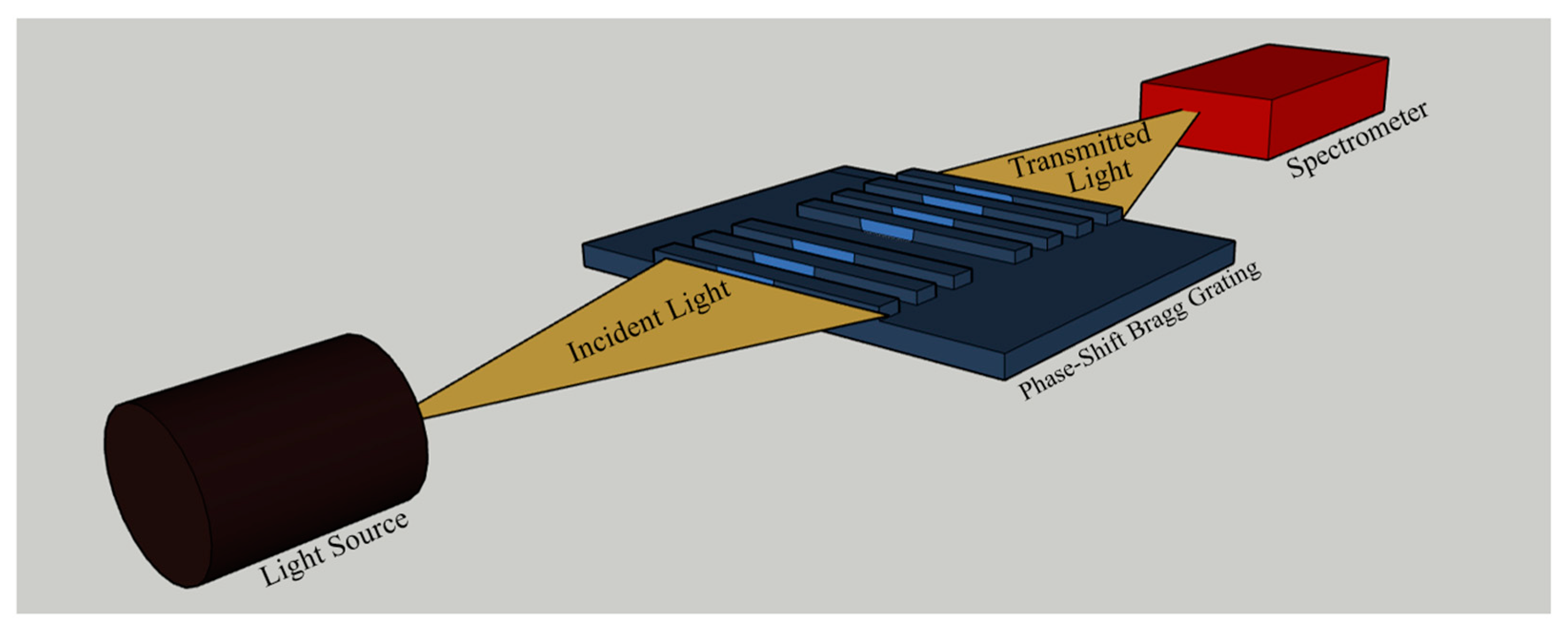
In order to understand the crucial role of determining the optimal number of periods in finalizing the sensor, it is important to consider the underlying physics of the device. The sensor relied on the phenomenon of a resonant cavity, where light is trapped and resonates within a specific region of the device. The size of the cavity determines the wavelength of the trapped light, while the refractive index of the surrounding material affects the resonance condition. By adjusting the number of periods in the device, we effectively changed the size of the cavity and, consequently, the resonant wavelength, which was detected by the spectrometer shown in
Figure 3. However, determining the best number of periods is not as straightforward as simply increasing it for improved sensor performance. As the number of periods increased, the change in the resonant wavelength eventually reached a plateau. Regardless of how many more periods were added, the resonant wavelength remained the same. This plateauing effect occurred because the variation in the Bragg grating parameters reached a limit where the size of the cavity was no longer significantly changing with each additional period.
Sensor response time is one of the key parameters to take into consideration when building a sensor. Generally, response time can be defined as the time needed to go from the initial value, according to the initial condition, to a certain percentage of the final value. The time constant for sensor response is typically used to describe the response time, which is equal to 1/e from the maximum value. It is found that this term refers to the duration required for the indicator of interest to shift from 10% to 90% of the total variation, especially in chemistry [
20]. This term denotes the duration necessary to achieve equilibrium or a steady state between the immobilized capture and the analyte of interest in a biosensor [
21]. The coating material (e.g., porous materials, polymers, or thin films) applied to the sensing region affects the response time, which usually becomes longer. This is due to the grain size and uniformity of the coating as well as the electrostatic interactions between the coating and the charged or polar site of the analyte [
22]. In addition, the matrix complexity in which the analyte is dispersed affects the biosensor’s response time: the more realistic the matrix (e.g., serum, plasma, blood), the more time it takes to respond, as the analyte’s mobility is expected to be lower [
23].
The stability of the sensor is affected by two important factors, which are the drift and fluctuations of a sensor. These parameters are often overlooked but deserve more attention. To ensure the stability of a sensor, the first step is to stabilize environmental conditions such as temperature, humidity, and induced strain. After stabilizing the environmental parameters, a stability test can be conducted. This involves measuring the time evolution of a specific parameter, such as λ
res, under fixed experimental conditions (e.g., 20 °C in air). The stability test allows us to evaluate the drift of the sensing system, which refers to any clear trend observed in the parameter over the measurement time [
24].
According to [
19], a long-term stability test was performed using two similar sensors of long-period Bragg grating (LPGs) in different environmental conditions. In one case, the sensor was placed inside a thermo-stabilized microfluidic system at a constant temperature of 23 °C. The drift on the parameter λ
res was found to be very low, indicating practical stability. The thermal fluctuations, or variations in temperature, were also minimal. In the second case, the sensor was placed in an open cell under controlled lab conditions. Here, the drift on the parameter λ
res was significantly higher compared to the first case. This indicates a less stable sensor performance. Additionally, the thermal fluctuations, or temperature variations, were larger in magnitude. Therefore, to ensure sensor stability, it is important to stabilize environmental parameters and closely monitor the drift and fluctuations of the sensor. By doing so, we can assess the degree of stability and take appropriate measures to optimize sensor performance.
Figure of merit (FOM) is a critical analytical parameter employed to assess the performance of sensors in terms of their sensitivity and full width at half maximum (FWHM). By quantifying the ratio between these two parameters, the FOM facilitates the standardized evaluation of sensor performance, enabling the identification and selection of optimal dimensions and periods for the sensor. Calculation of the FOM provides an objective measure that enables the detection and quantification of minute changes in refractive index, thereby enhancing the sensor’s ability to accurately sense and quantify variations in the surrounding environment. The advantages of achieving a high FOM extend beyond performance evaluation, encompassing considerations of application suitability. Through the utilization of the FOM, sensor requirements such as high sensitivity or rapid response can be assessed and tested effectively. In this manner, the FOM serves as a valuable tool for evaluating whether the sensor meets the specified requirements. By analyzing the effects of different parameters on the FOM, critical elements influencing sensor performance can be identified, enabling informed decisions for enhancing sensitivity and optimizing sensor design. Furthermore, a high FOM is indicative of a narrowing spectrum, wherein changes in the FWHM significantly impact the FOM value. Consequently, even with a relatively lower sensitivity, a sensor exhibiting a high FOM would demonstrate a substantial power variation between different refractive indices. This characteristic enhances the sensor’s overall performance, enabling the accurate observation of changes in refractive indices. As a result, sensors with a high FOM exhibit superior performance characteristics, with the ability to detect and quantify variations in the surrounding environment effectively.
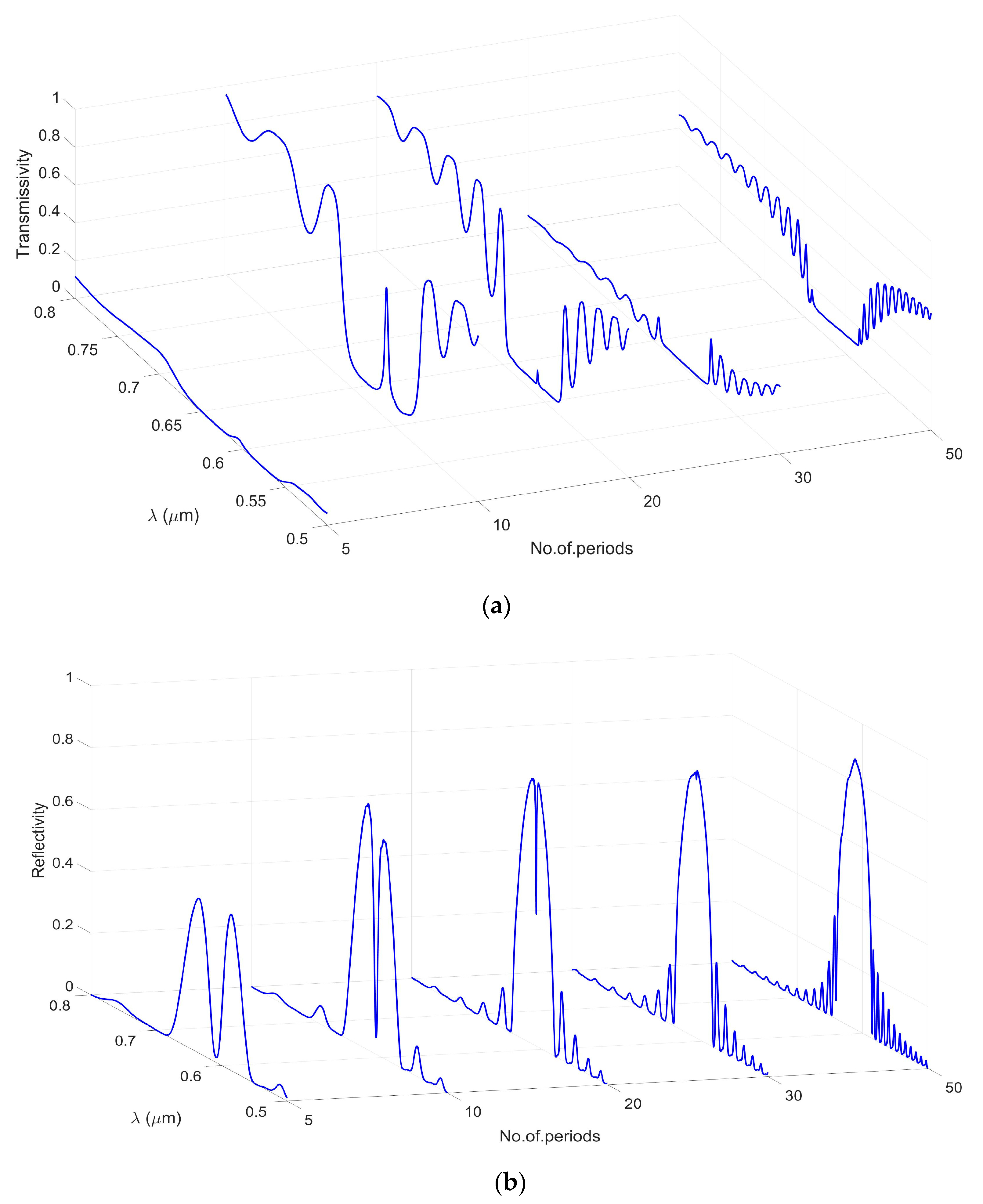
Interestingly, despite the resonant wavelength plateauing, it has been discovered that the figure of merit (FOM) of the sensor continued to increase as we added more periods. This is because the FOM considers not just the resonant wavelength, but also the width of the transmission peak. As we added more periods, the transmission peak became narrower and, hence, the FOM increased. However, it has been observed that there was a limit to the number of periods we could add before the peaks higher than the optimal 20-period design disappeared. This limitation was due to inherent imperfections in the material, which caused losses in the device that increased with more periods. To optimize the number of periods while considering these aspects, we employed the finite-difference time-domain (FDTD) solver. This solver allowed us to arrive at the optimal design by considering all these factors. The reflected and transmission spectra shown in
Figure 4 below demonstrate the effectiveness of this design optimization process.
The simulation has been conducted to determine the optimal dimensions and other dependent parameters of the phase-shifted Bragg grating sensor. These parameters include the etching depth, grating length, and number of periods. By varying these parameters and examining the resulting spectra, it was possible to identify the configurations that yielded the highest FOM and sensitivity. We observed that as the number of periods increased, the power of the Bragg wavelength decreased. Consequently, we aimed to select the peak with the highest power value. However, we encountered a trade-off between peak power and other characteristics such as the FWHM and sensitivity. While peaks with high power exhibited large FWHM and lower sensitivity, we devised a stepwise process that involved calculating the sensitivity and FWHM for each peak. This enabled us to identify peaks with both high sensitivity and FOM.
Table 1, presented below, illustrates the values of sensitivity and FWHM corresponding to different numbers of periods. Through this analysis, we determined that when the number of periods is set to 20, the phase-shifted Bragg grating sensor achieves the highest sensitivity and FOM. Therefore, based on our findings, we conclude that configuring the phase-shifted Bragg grating sensor with 20 periods yields the optimal combination of sensitivity and FOM.
The FDTD solver is used to calculate the transmission and the reflected spectrum at different cladding refractive index.
Figure 5a,b shows the spectrum that has been calculated. As can be seen, this is the shape of a shifted Bragg grating; we used this structure as it gives us sharper pack and, therefore, FOM. We investigated this process using Eigen mode expansion solver (EME) first; however, it did not give any change between the reflected resonance peaks at different cladding index. This was because the EME solver only calculates the mode in one cell and then expands it without making it propagate through the structure. However, using FDTD allowed us to propagate the mode and show us the change in the reflected and the transmission spectrum, as can be seen below.
In this case, the water solution that interacts with bacteria will accordingly change the effective index, therefore, the reflected wavelength will change. This device gives the opportunity to detect change in the cladding refractive index up to
The waveguide sensitivity,
, is the ratio of the variation in the effective index of the mode to the variation in the index of the medium,
. The sensing waveguide structure determines the value of
. Moreover, the sensitivity of device,
, is the ratio of the variation in the Bragg wavelength to the variation in in the effective index of the mode.
Figure 6 shows the cladding index versus the reflected wavelength, and the slope that represent the sensitivity has been calculated using Equation (3), to be equal to
.
Finally,
Table 2 shows a comparison between our Bragg grating optical sensor and other sensors; we have found that our sensor has the best sensitivity. However, what sets our sensor apart is our use of visible light, which has low loss and offers several other benefits in sensing applications. Visible light is readily available and can be easily manipulated using standard optical components such as lenses, mirrors, and filters. This makes it a versatile tool that can be used in a wide range of applications. This versatility enables its deployment across a wide range of applications. One key advantage of visible light is its non-ionizing nature, ensuring safety in various environments where other sensor types relying on X-rays or gamma rays would not be suitable. Moreover, visible light is less prone to scattering and absorption in many materials, resulting in high measurement resolution and accuracy. Additionally, visible light can penetrate common materials, such as glass and plastics, without significant attenuation. This capability enables the monitoring of internal material properties, including temperature and strain in structures, without invasive sensors.
4. Proposed Sensor Fabrication Steps
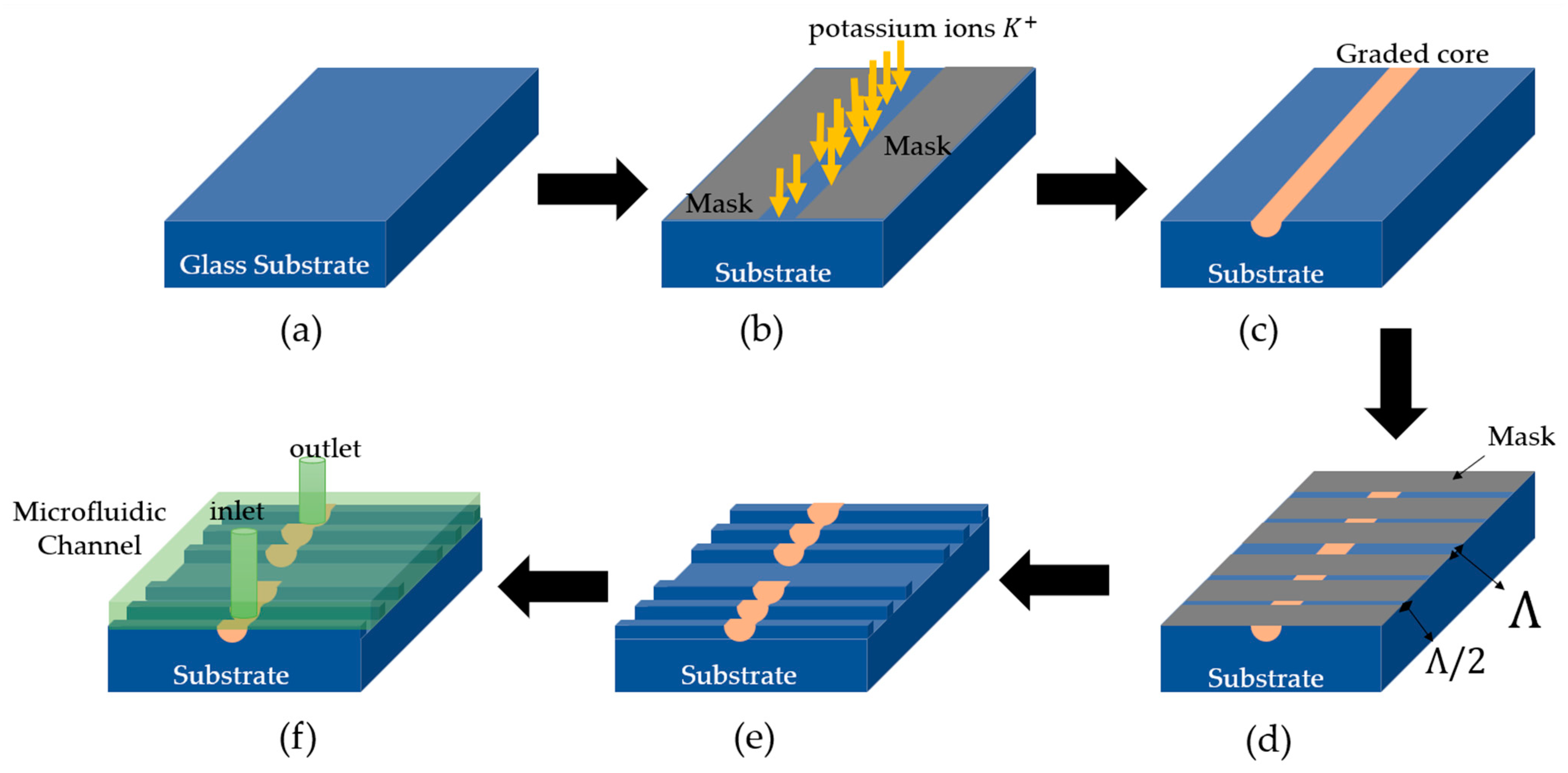
The proposed fabrication process of the phase shift Bragg grating sensor involves a series of sequential steps, as depicted in
Figure 7. The first fundamental step entails a meticulous cleaning procedure to ensure the elimination of any impurities or contaminants that could potentially compromise the quality and performance of the sensor (
Figure 7a). Subsequently, a thin-film layer of aluminum, with a precisely controlled thickness of 200 nm, is deposited onto the surface of the sample using the vapor phase deposition technique. This aluminum film functions as a mask, facilitating the subsequent formation of waveguides, wherein the width and positions are meticulously regulated to achieve the desired optical properties of the sensor. In the third step, an ion exchange process is performed in a molten bath consisting of pure potassium nitrate (KNO
3) at a temperature of 400 K. This process results in a maximum index change of 0.008 [
28], with potassium ions diffusing into the glass substrate at a rate of 1.6 μm
2/h, as illustrated in
Figure 7b. The duration of the process is carefully controlled to be one hour, in accordance with the prescribed conditions of the proposed Equation (1). During this process, sodium ions are substituted by potassium ions, leading to a significant increase in the refractive index near the surface of the substrate (
Figure 7e). The diffusion parameters, including temperature, exchange time, and the width of the open windows, play a crucial role in determining the quality of a single-mode straight waveguide with low loss at a specific wavelength. Hence, these parameters should be thoughtfully selected based on the design specifications of the sensor. In the fourth step, an additional layer of thin aluminum film is deposited onto the waveguide core, and the pattern of the phase shift Bragg grating is defined by etching the core (
Figure 7d). Various techniques, such as hydrogen fluoride (HF) addition or selective laser etching, can be employed to etch the glass substrates. The choice of etching method depends on factors such as the desired etching depth, complexity of the pattern, and available resources. The etching process must ensure that the etching depth matches the core thickness, while the etching width should be half the period for the grating slots and one period for the phase shift slot. This etching process not only enhances the sensitivity of the sensor by inducing a periodic modulation of the refractive index along the waveguide but also provides a pathway for water flow to reach the sensor surface. The fifth and final step involves the removal of the aluminum mask, resulting in the attainment of the final structure of the phase shift Bragg grating sensor (
Figure 7e). To facilitate the introduction of a salmonella solution and expedite its detection, the utilization of a microfluidic channel as a fluid conduit has been proposed (
Figure 7f). This microfluidic channel serves to efficiently deliver the salmonella solution to the sensor surface, aiding in the detection process.
5. Discussion
The proposed on-chip optical sensing system utilizing ion exchange technology and phase-shifted Bragg grating design offers several advantages over existing sensors. The optimized sensor geometry achieved maximum sensitivity and figure of merit, making it highly responsive to changes in refractive index with low fabrication costs. The ion exchange process allowed for precise refractive index control, further enhancing the sensor’s sensitivity and figure of merit. The graded-index waveguide and phase-shifted Bragg grating structure also contributed to the sensor’s high sensitivity, surpassing other Bragg grating sensors in water-based sensing applications.
The proposed sensor design could enable early identification of contaminated food or water, allowing for prompt action to be taken to prevent the spread of infection and protect public health. Moreover, the sensor’s high sensitivity, versatility, and portability make it suitable for field applications. The ability to perform sensing and monitoring in situ and in real-time is highly desirable in many fields, from environmental monitoring to biomedical sensing. The proposed sensor design could be integrated into portable systems for field applications, enabling rapid and accurate analysis of samples in remote locations.
Looking forward, there are several avenues for future research that could build upon the proposed sensor design. For example, further studies could explore the use of different materials and designs to optimize the sensor’s sensitivity and figure of merit for specific applications. Additionally, research could focus on developing new applications for the sensor in different fields, such as in the detection of other types of bacteria or in the analysis of complex biological samples.
