1. Introduction
In recent years, laser wireless power transmission (LWPT) has attracted considerable interest due to its long transmission distance, good mobility flexibility, and high energy density [
1]. Laser wireless power transmission systems consist of a laser system at the transmitter, a transmission medium, laser power converters (LPCs), and a power management system at the receiver.
Researchers are most concerned with the efficiency of the laser wireless power transmission system, which is directly related to the efficiency of the system and the maximum output power (MPP) of the array of LPCs. Due to the uneven distribution of light intensity during long-distance laser transmission or local contamination on the surface of LPCs, there is a risk of current mismatch among the LPCs in the array. Incorrect connections can result in a significant reduction in the array output power or even cause damage to the LPCs. Therefore, circuit reconfiguration of the array plays a decisive role in obtaining maximum power at the photovoltaic (PV) array. In [
2], an optimization algorithm based on Series-Parallel (SP) and Total-Cross-Tied (TCT) structures is proposed to obtain the optimal SP and TCT structures for Gaussian beams emitted from lasers. The reconfiguration algorithm in [
3] reconnects the local shadows in the array to maximize the obtained electrical power. Modeling simulations and experiments under four shading conditions are also used to verify the effectiveness of the algorithm. Reference [
4] comparatively investigates the maximum power of SP, TCT, and Bridge-Link (BL) array structures under six shading conditions. The simulation results show that TCT has the highest power point under the six shading conditions.
Reference [
5] improves the interconnection module inside the photovoltaic array to reduce the mismatch loss due to local shading. SP, TCT, and BL structures were experimentally obtained with better connections. Reference [
6] simulates and experimentally investigates the effect of the variation of each cell connection on the output power of partially shaded PV arrays. Reference [
7] investigates the proposed structure under shading conditions compared to the conventional triple connection structure, and the obtained electrical power is substantially increased compared to the TCT configuration. Reference [
8] demonstrates that the local shading condition substantially reduces the MPP of the photovoltaic array and provides a method for rearranging the array under various shading conditions. Reference [
9] proposes a dynamic interconnection method for PV modules based on an irradiance equalization algorithm. Meanwhile, [
9] proposes an irradiance equalization algorithm to obtain the MPP by controlling the switching matrix. By optimizing PV connections under different shielding conditions, [
10] achieves a higher MPP. Reference [
11] quantifies the power loss of three types of arrays in conditions of shadowing. Reference [
12] suggests a novel TCT connection method for various shielding conditions. Reference [
13] utilizes the Tom-Tom configuration connection method to achieve greater output power under varying shielding conditions. An improved strategy is proposed to optimize the dynamic photovoltaic array (DPVAS) using an “irradiation equalization” (IEQ) reconstruction strategy [
14].
In summary, the current research on the reconfiguration of PV arrays is primarily based on the irradiance balancing principle for circuit reconstruction [
15,
16,
17]. The essence of this approach is to enhance the output power by reducing current mismatch. In the field of solar PV arrays, both static and dynamic circuit reconstruction technologies have become relatively mature, attracting widespread attention and applications [
18,
19]. However, in the realm of LWPT, there remains a significant gap in the study and application of static and dynamic circuit reconstruction techniques. This indicates that, in this particular domain, further in-depth research and practical applications are necessary to optimize the circuits of PV arrays in LWPT. Future efforts should focus on filling this research gap to advance the development of LWPT technology and enhance its efficiency in real-world applications. When semiconductor lasers are used in long-range wireless power transmission systems, the light intensity distribution at the receiver is not uniform, even though the laser is shaped and homogenized. Additional research needs to be explored concerning the most effective configuration of the array circuit. In this paper, we present an efficient and feasible circuit design for arrays under certain static non-uniform light intensity or shadowing conditions to efficiently obtain the maximum power at the receiver array and decrease the number of local MPP points.
This paper employs an 808 nm six-junction LPC to assemble a 10 × 10 PV array. Under laser illumination of 300 W, a power transmission experiment is conducted at a distance of 20 m. Furthermore, this paper optimizes the circuit reconfiguration of a 5 × 5 array with static non-uniform light intensity distribution through the algorithms. This paper investigates LWPT characterized by a comparatively substantial output power, a sizable sample size, and specific long-range transmission. The research approach involves a synergistic combination of experimental methodologies and theoretical studies.
2. Materials and Methods
The PV vertical multi-junction structure, which includes the GaAs contact layer and the InGaP lateral conduction layer (LCL), was designed to operate at 808 nm. Six GaAs subcells were interconnected by tunnel junctions, as shown in
Figure 1a. Each subcell has an Si-doped GaAs emitter and a C-doped GaAs base sandwiched between the InGaP window and back surface field layers. A p++−AlGaAs/n++−AlGaAs alloy makes the tunnel junctions transparent to the input beam. Lambert’s law was used to simulate the thickness of each subcell, with an absorption coefficient of 14,000 cm
−1. The group III and V sources were trimethylindium (TMIn), trimethylgallium (TMGa), AsH
3, and PH
3. The GaAs LPC wafers were grown in an MOCVD (metal–organic chemical vapor deposition) system at a temperature of 690 °C and a pressure of 50 mbar, with C (CBr
4 source), Si (Si
2H
6 source), and (or) Te (DeTe source) used as p-type and n-type dopants, respectively [
20]. To improve thermal conductance, LPCs were placed on copper-plated ceramic heat sinks with silver paste between them, as shown in
Figure 1b. I–V measurements were performed using an 808 nm laser and an electronic load meter.
The output characteristics of the LPCs can be equivalently analyzed by a single-diode circuit model, as shown in
Figure 2a. When setting the temperature to 25 °C, Equations (1)–(3) express the LPC output characteristics [
15]:
The meanings of the parameters are shown in
Table 1.
The I–V curve of an LPC can be accurately modeled using the seven input parameters Isc, Uoc, Um, Im, Rs, Rsh, and G. However, for fast calculations, the seven-parameter model is simplified to a five-parameter model in practical applications. The five-parameter ideal diode model can reduce the workload of theoretical simulation calculations, allowing for a rapid evaluation of the analysis of the actual situation and the output characteristics of the PV array. The process for reducing the seven-parameter model to the five-parameter model is described below.
Since R
s of the LPC is small enough to approximate 0, and R
sh is huge enough to consider infinity, the single-diode equivalent circuit model can be simplified to an ideal diode circuit model, as shown in
Figure 2b. The PN junction short circuit can be expressed using the following equation:
Therefore, the ideal diode output characteristic can be expressed as the following equation:
When the LPC is open circuit, V
oc can be expressed using the following equation:
According to the I–V characteristics of the LPC output, there is a maximum power point that maximizes the output power of the LPCs. Set the maximum output power as P
m and the other equations as follows:
In this case, the output expression of the LPC can be expressed as the following equation:
At this time, five parameters, I
sc, U
oc, U
m, I
m, and G, can represent the output characteristics of the LPC, which better fit the output I–V characteristics. To verify the matching degree between the output characteristics of the model and the measured LPC, this paper compares the simulation results and the actual measured results under the condition of 1 W/cm
2, as shown in
Figure 3a,b. It can be seen from the comparison that the simulation results fit well with the actual test results, which can fully meet the prediction and verification function of the theoretical simulation of the array on the experimental results. The parameters of the LPC are detailed in
Table 2.
3. Results
3.1. Experiment
The distribution of laser intensity after long-distance transmission is not uniform. During transmission, atmospheric interference occurs, and the light intensity distribution on the PV array must be distinct. Significant power will be lost if the PV array employs an unsuitable array connection. Based on the conclusion in [
4] that the TCT configuration has the best output quality, the circuit of the TCT configuration is optimized in this paper. This paper presents an efficient and reliable TCT array circuit connection optimization method under a non-uniform laser to reduce power loss. In this paper, the specific concept of the optimization strategy algorithm is presented.
In this paper, the experimental validation is conducted in a realistic and specific setting. In this experiment, the long-range transmitting laser source is an 808 nm semiconductor laser that, after 20 m of transmission, reaches an LPC’s array composed of 100 LPCs. The arrays were divided into four 5 × 5 arrays, shown in
Figure 4a.
Figure 4b depicts the arrangement and number of 5 × 5 LPC arrays. Additionally, the I–V curve of the LPC’s array is tested to identify the I
sc and express the graph of I
sc distribution.
Figure 5 depicts the obtained I
sc distributions under 300 W non-uniform laser irradiation, which is a vital parameter of the optimization algorithm.
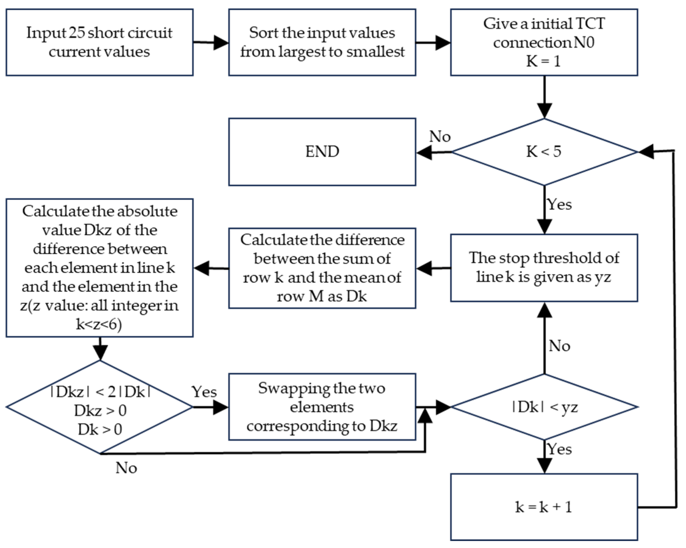
3.2. 5 × 5 Algorithm Block Diagram
There are 25 possible TCT configurations for an LPC 5 × 5 array. The combinations would be very computationally intensive and require much time if every possible combination method was to be considered. Reference [
14] provides an algorithm for rapidly obtaining optimized TCT connections using a simple sorting method, but the accuracy of the optimization needs to be improved. This paper develops a more precise automatic algorithm to take advantage of the faster computation time. The algorithm proposed in [
14] repeats the search calculation until the threshold value is satisfied and then terminates. In this paper, a 5 × 5 array reconstruction algorithm is obtained by optimizing the algorithm to obtain the initial array, which connects to an optimized circuit design distribution. As discussed earlier in this paper, most search algorithms for TCT architectures are either computationally expensive or provide solutions that are close to optimal only under Gaussian beam irradiation. Therefore, under non-uniform irradiation conditions, there is a need for a search algorithm that can provide optimal solutions within an acceptable time complexity. The TCT configuration algorithm proposed in this paper utilizes the concepts of irradiance balancing and current matching to establish the optimal structure. Ensuring that the sum of currents in each row is nearly equal is crucial for maximizing the output power of the PV array. This algorithm is based on the idea of array reconstruction.
Figure 6 depicts the block diagram.
The algorithm block diagram’s fundamental logic is calculated as follows:
Input and arrange 25 short-circuit current values in descending order.
Give an initial TCT distribution N0 and set the number of rows to k = 1.
Provide the stopping threshold yz for row K and calculate the difference Dk between the sum of row K and the mean of row M.
Calculate the absolute value of the difference between each element of the row k and the element of the row z, Dkz. (k < z < 6; all integers).
Compare the size of 2|Dk| and |Dkz|; if Dk > 0, Dkz > 0, |Dkz| < 2|Dk|, swap the two elements of Dkz. On the contrary, judge the size of |Dk| and yz. If |Dk| ≥ yz, the jump is executed (3). If |Dk| < yz, then k = k + 1 and execute (7).
Compare the size of |Dk| and yz; if |Dk| < yz, then k = k + 1. If |Dk| ≥ yz, then execute (3).
If k < 5, repeat (3) to (6), or else, end the run.
The input values are the initial distribution’s I
sc values. The optimized current distribution is obtained by rearranging the circuit connection optimization algorithm, and then the optimized TCT circuit connection method is accepted. The short-circuit current distributions for the four 5 × 5 arrays after the optimization, according to the algorithm provided in this paper, are depicted in
Figure 7.
3.3. Theoretical Simulation and Experiment
To assess the effectiveness and dependability of the TCT connection optimization algorithm, first, the TCT connection and the optimized TCT connection are simulated and validated using an ideal equivalent diode model for four cases to predict the experimental outcomes.
Figure 8 depicts the simulation results.
The simulation results indicate that the maximum power of the four TCT structures is 21.33 W, 26.70 W, 16.42 W, and 15.71 W. After optimizing the connection, the maximum power obtained is 29.15 W, 30.40 W, 22.33 W, and 24.11 W. In comparison, the maximum power increased by 36.66%, 13.86%, 35.40%, and 53.49%. Compared to the standard TCT connection, the optimized TCT connection increases the maximum power significantly. In addition, the output has a single maximum power point, making it easier to obtain maximum power in the future.
In order to further validate the predictive reliability of the optimization algorithm and simulation results, four 5 × 5 arrays are experimentally validated in this paper.
Figure 9 depicts the experimental results.
Similarly, the experimental results reveal that the maximum power obtained by TCT configuration in four actual scenarios is 18.21 W, 21.18 W, 13.07 W, and 11.74 W. The optimal TCT connection yields a maximum power of 23.60 W, 19.18 W, 17.73 W, and 18.37 W. Compared to the pre-optimization period, the maximum power in the four arrays increased by 56.49% after optimization.
4. Discussion
Almost all of the TCT connections optimized with this algorithm have high maximum power and nearly unique maximum power points, which can significantly improve the efficiency of obtaining the maximum power point in the future. In addition, the dependability and predictability of simulation results are verified.
Figure 10 shows the comparison of the maximum power of four arrays. The difference between the experimental and simulation results can be attributed to the utilization of an ideal model and the fact that the actual performance of each LPC is different.
The algorithm proposed in this paper enables higher power outputs from a PV array under non-uniform laser illumination. In comparison to the other circuit reconstruction algorithms, the proposed algorithm has the advantage of being simpler and more efficient. Additionally, we have, for the first time, constructed a long-distance, high-power laser transmission system using 808 nm six-junction LPCs and applied the proposed reconstruction circuit algorithm in practical scenarios. We only conducted power transmission experiments in a static environment, specifically for indoor laser power transmission. In real-world environments, atmospheric disturbances, turbulence, and other factors can cause real-time changes in the distribution of lasers on PV arrays. To achieve an MPP output under such conditions, real-time adjustments to the circuit control are necessary, and this can be facilitated through artificial intelligence [
14].
The algorithm proposed in this paper is currently applicable only to a 5 × 5 TCT PV array. If it is to be applied to larger or smaller PV arrays, adjustments to the algorithm statement in the flowchart are required, specifically changing “K < 5” to the corresponding array specifications. Furthermore, attention will be given to potential issues related to LWPT systems, such as addressing human exposure to lasers, environmental impacts, and compliance with safety standards. The research will also focus on the development of LPCs in the eye-safe wavelength range and the reliability study of LWPT systems. Firstly, the laser transmission process may pose risks such as burns to the human body and the potential for fire accidents. Therefore, it is necessary to wear appropriate protective gear and implement warning symbols during the implementation of wireless energy transmission. Secondly, the optimization strategy proposed in this paper is highly reliable as it remains unaffected by temperature variations. However, in the presence of interference where parts of the laser spot are obstructed, resulting in changes in the laser distribution on the PV array, it becomes necessary to reoptimize the PV array connection based on this laser distribution. The array optimization algorithm proposed in this paper is primarily influenced by changes in the laser spot distribution. While the components, maintenance requirements, and overall system lifespan of the PV array components may lead to a decrease in the maximum power output, the output characteristics of the optimization algorithm remain unchanged. Therefore, this optimization strategy ensures the long-term reliability and stability of the PV array.

 ,
, 


