Article

The Spiral Spectrum of a Laguerre–Gaussian Beam Carrying the Cross-Phase Propagating in Weak-to-Strong Atmospheric Turbulence

1
Shandong Provincial Engineering and Technical Center of Light Manipulations & Shandong Provincial Key Laboratory of Optics and Photonic Device, School of Physics and Electronics, Shandong Normal University, Jinan 250358, China
2
Collaborative Innovation Center of Light Manipulation and Applications, Shandong Normal University, Jinan 250358, China
3
School of Physics and Engineering, Henan University of Science and Technology, Luoyang 471023, China
4
Joint Research Center of Light Manipulation Science and Photonic Integrated Chip of East China Normal University and Shandong Normal University, East China Normal University, Shanghai 200241, China
*
Authors to whom correspondence should be addressed.
Photonics 2024, 11(2), 148; https://doi.org/10.3390/photonics11020148
Submission received: 11 January 2024 / Revised: 29 January 2024 / Accepted: 1 February 2024 / Published: 4 February 2024

Abstract

:
In communication links, the presence of atmospheric turbulence leads to crosstalk between the orbital angular momentum (OAM) states, thereby limiting the performance of information transmission. Thus, knowledge of the effect of turbulence on the spiral spectrum (also named the OAM spectrum) is of utmost importance in the field of optical communications. However, most of the existing studies are limited to weak turbulence calculation models. In this paper, based on the extended Huygens–Fresnel integral, the analytical expression is derived for the mutual coherence function of a Laguerre–Gaussian beam carrying the cross-phase and propagating through weak-to-strong anisotropic Kolmogorov atmospheric turbulence; subsequently, the analytical expression is used to study the behavior of the spiral spectrum. The discrepancies in the spiral spectrum between weak and strong turbulence are comparatively studied. The influences of the cross-phase and the anisotropy of turbulence on the spiral spectrum are investigated through numerical examples. Our results reveal that the cross-phase determines the distribution of the spiral spectrum. The spiral spectrum can be tuned to multiple OAM modes through the adaptation of the cross-phase coefficient. Moreover, increasing the cross-phase coefficient can reduce both the discrepancies of the spiral spectrum under two computational methods and the effects of the anisotropic factors of turbulence on the spiral spectrum.

1. Introduction

A beam with a spiral phase, described by exp(ilθ), is referred to as a vortex beam [1]. Each photon of the vortex beam carries an orbital angular momentum (OAM) of lℏ, where l is the topological charge, θ is the azimuthal angle, and is the reduced Planck constant [2]. Due to carrying discrete topological charges and their close relationship with OAM, the interest in vortex beams has been increasing and has yielded a significant return in many applications, including optical imaging [3,4], optical trapping [5,6,7], holography [8], optical coding [9], quantum information processing [10] and optical measurement [11]. It is worth noting that these modes provide a (theoretically) infinite and easily realized alphabet for encoding information and have been used extensively in both free-space and fiber-optical communications, in particular through the use of OAM multiplexing and modulation (encoding/decoding) [12,13,14,15]. In addition to amplitude, phase, polarization and frequency, OAM modes have been proposed as a new set forming the basis of carrier signals and allowing, in principle, an increase in the channel transmission capacity [16,17,18,19].
However, when vortex beams are used for optical communications, the presence of atmospheric turbulence in communication links will inevitably induce phase distortion, beam wander and scintillation, resulting in the dispersion of OAM modes and crosstalk between OAM states, thereby having the potential to limit the performance of information transmission [20,21,22,23]. Hence, knowledge is essential for understanding the interaction of turbulence and OAM modes. Up to now, a wide variety of studies has been carried out to reveal the influence of turbulence on the propagation characteristics of OAM modes [24,25,26,27,28,29], including investigations of Laguerre–Gaussian beams, Lommel beams, Airy beams, elliptic Gaussian vortex beams and Bessel beams. When calculating the spiral spectrum of vortex beams in turbulence, these studies have adopted the most widely used single-phase screen perturbation (SPSP) method, that is, regarding the effect of turbulence as a random phase screen that only exists at the receiver plane and without considering the turbulence between the transmitter and the receiver. However, strictly speaking, this type of method is only valid in weak fluctuation ranges because the interaction between turbulence and OAM modes during propagation is ignored. In actual communications, turbulence pervades the entire propagation channel, gradually accumulates and becomes stronger as the propagation distance increases. To take this effect into account, the multiple-phase screen method has been proposed [30,31,32]; however, it is a purely numerical simulation approach, which is relatively time-consuming when calculating complex light sources. In addition to the above method, only a few studies in the literature have focused on analyzing the spiral spectrum under high levels of turbulence [33,34].
Recently, the increasing requirements for communication capacity [35] and information encryption technology [36] have prompted scholars to pay attention to the on-demand requirements for manipulation of the OAM spectrum. The previous research has provided a variety of schemes to tailor the OAM spectrum or simultaneously generate multiple OAM components in one beam, such as the pattern-search algorithm [37], mode iteration [38] and the use of pinhole plates [39]. In 2022, Fu and colleagues proposed a simple azimuthal binary phase modulation scheme for a high-dimensional OAM comb, which avoided the shortcomings of complex systems, these being time-consuming and showing low efficiency, which was demonstrated in previous schemes [40]. However, their study did not consider the effect of atmospheric turbulence on the OAM spectrum. On the other hand, a new type of twisting phase known as the cross-phase has been explored by various research groups [41,42,43,44]. The cross-phase is a quadratic phase structure distinct from the ordinary twist phase [45], which finds versatile applications in coherent mode conversions [41], beam rotations [42], optical vortex manipulations [43], and flexible beam focuses [44]. In particular, the cross-phase has been used to enhance the anti-turbulence ability of light beams during transmission [46]; however, so far, its use has been limited to non-vortex circumstances. It is worth mentioning that special structured light fields can effectively mitigate the negative effects induced by atmospheric turbulence [47]. More recently, DiouF et al. proposed and demonstrated a new structural light called the space-time light sheet, which is resistant to atmospheric turbulence and speckle [48,49].
Here, the spiral spectrum of a Laguerre–Gaussian (LG) beam embedded with the cross-phase propagating in anisotropic Kolmogorov turbulence is the object of our study. Based on the extended Huygens–Fresnel (eHF) principle, which is applicable to both cases of weak and strong turbulence, the analytical expression for the mutual coherence function of an LG beam carrying the cross-phase at the receiver is derived. The effects of turbulence parameters and the cross-phase on the spiral spectrum are analyzed. Our results show that a cross-phase can convert a single pure OAM mode into a beam with a wide OAM spectrum, which can be easily tuned to multiple OAM modes by adapting the cross-phase coefficient. In addition, by modulating the cross-phase, reductions ensue in the discrepancies in the spiral spectrum obtained by the SPSP and eHF methods, as well as in the influence of the anisotropic factors of turbulence on the spiral spectrum.

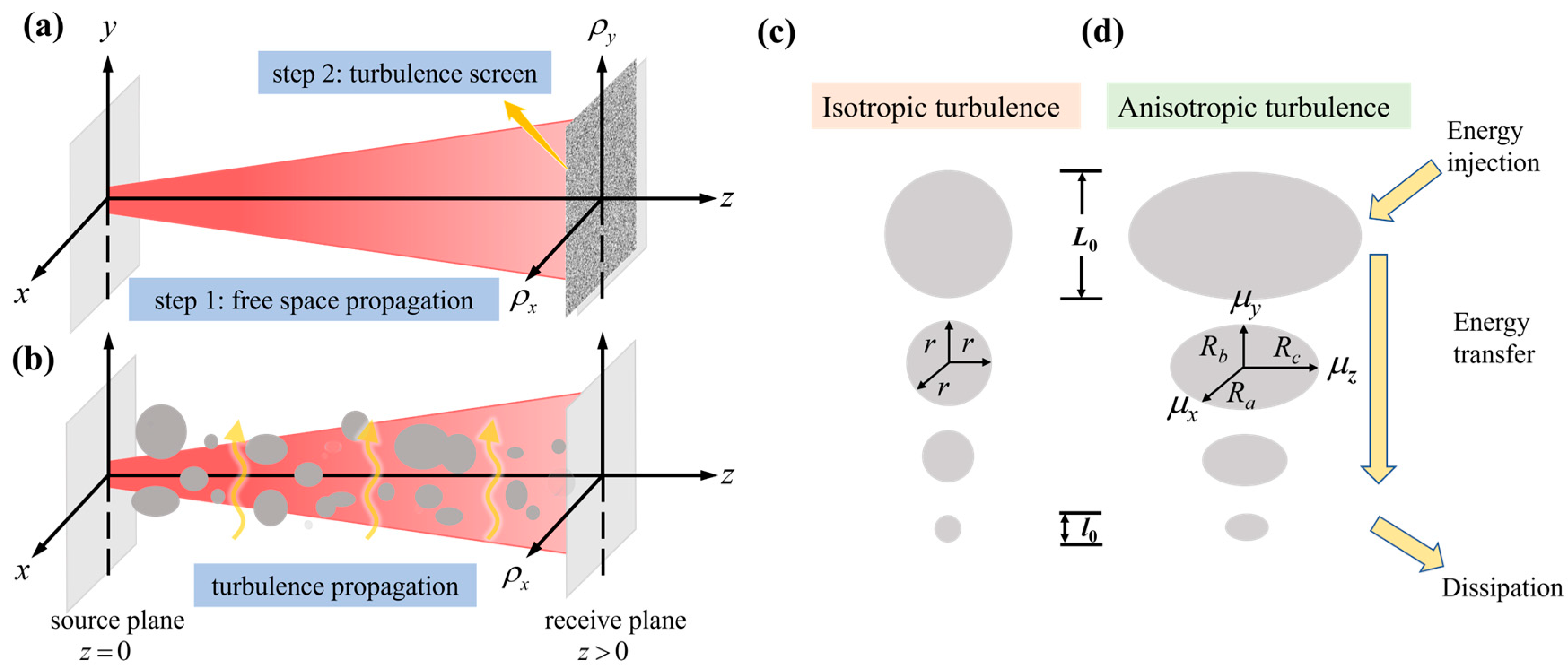
2. Propagation of a Laguerre–Gaussian Beam Carrying the Cross-Phase in Atmospheric Turbulence

Unlike the twisted phase, which only exists in partially coherent beams, the cross-phase is a separable secondary phase structure, making it easy to embed in other light fields [41]. We consider the example of an LG beam carrying the cross-phase with a radial mode index p = 0 and an azimuthal mode index l, whose electric field in the source plane has the following form:
E 0 ( r ) = C r | l | exp ( r 2 w 0 2 ) exp ( i l φ ) exp ( i u x y ) ,
where r = (x, y) and φ = arctan(y/x) denote the radial coordinate and azimuthal angle coordinate, respectively. C and w0 are the normalizing constant and initial beam width, respectively. The quantity l refers to the topological charge [1]. The last term, exp(iuxy), is the cross-phase structure, where the quantity u is a measure of the strength of the cross-phase. When the value of u is equal to zero, Equation (1) reduces to an LG beam with a radial mode index of p = 0.
It is known that when a vortex light field is transmitted through atmospheric turbulence, its original OAM mode purity will be reduced due to the influence of phase distortion caused by that atmospheric turbulence. To explore the spiral spectrum of a beam propagation through atmospheric turbulence, two propagation modes (i.e., the SPSP method and the eHF method) are commonly used. The SPSP method [24,25,26,27,28,29] assumes that the transmission path from the source plane to the receiving plane is in a vacuum without turbulence, and the cumulative effect of the turbulence on the channel is equivalent to single random phase perturbation on the beam at the receiving plane, as shown in Figure 1a. In the eHF method [50,51], the atmospheric turbulence fills the entire propagation path, and the turbulence thereby affects the beam’s statistical properties during propagation, as shown in Figure 1b. Compared with the former, which is only effective under conditions of weak turbulence, here we focus on the calculation method based on the eHF principle, which is valid from weak to strong turbulence. Based on the eHF integral, the mutual coherent function of an LG beam carrying the cross-phase in the receiving plane after propagating in atmospheric turbulence can be written as follows [51]:
Γ ( ρ 1 , ρ 2 , z ) = 1 λ 2 z 2 E 0 ( r 1 ) E 0 * ( r 2 ) exp [ i k 2 z ( ρ 1 r 1 ) 2 i k 2 z ( ρ 2 r 2 ) 2 ] × exp [ ψ ( r 1 , ρ 1 , z ) + ψ * ( r 2 , ρ 2 , z ) ] d 2 r 1 d 2 r 2 ,
where ρi = (ρix, ρiy) (i = 1, 2) denote the transverse position vectors in the receiving plane (z > 0). λ and the asterisk stand for the wavelength of the light beam and the complex conjugate, respectively. The angle brackets represent the ensemble averaging over the turbulence fluctuations, where the term ψ (r, ρ, z) is turbulence-induced complex perturbations of a spherical wave propagating from (r, 0) to (ρ, z).
For the propagation of the optical wave in the atmosphere, the refraction index is one of the core parameters affecting the propagation characteristics of optical waves. This index is very sensitive to small-scale temperature fluctuations that, combined with turbulent mixing, lead to the random behavior of the refractive index in the atmosphere. To visualize the development of a turbulent structure, see the details provided in Figure 1c, based on the energy cascade theory for the homogeneous and isotropic case. Under the influence of inertial forces, large eddies split into smaller eddies, forming a continuum of eddy sizes, which are used to transfer energy from a macroscale L0 (the outer scale of turbulence) to a microscale l0 (the inner scale of turbulence). The eddies in this model are often assumed, on average, to be isotropic. However, at ground level, this isotropic behavior is broken since the temperature of the ground is usually much higher than that of the atmosphere; this is especially true in the daytime in tropical or desert areas. As a result, the refractive index fluctuations in the vertical direction are stronger than those in directions that are parallel to the ground. Figure 1d shows the development of eddies in the anisotropic case, in which the eddies become ellipsoids. To generalize our calculation results, we assume that the turbulence is anisotropic and obeys the Kolmogorov spectrum when calculating Equation (2). According to the turbulence spectrum model with the power law index α = 11/3 proposed in reference [26], the second-order statistics of the complex phase perturbation may be represented as follows:
exp [ ψ ( r 1 , ρ 1 , z ) + ψ * ( r 2 , ρ 2 , z ) ] = exp [ T μ z ( ρ x d 2 μ x 2 + ρ y d 2 μ y 2 + x d 2 μ x 2 + y d 2 μ y 2 + ρ x d x d μ x 2 + ρ y d y d μ y 2 ) ] ,
with
ρ d = ρ 1 ρ 2 = ( ρ x d , ρ y d ) = ( ρ 1 x ρ 2 x , ρ 1 y ρ 2 y ) r d = r 1 r 2 = ( x d , y d ) = ( x 1 x 2 , y 1 y 2 ) T = 0.0033 π 2 k 2 z C n 2 [ η κ m 5 / 3 exp ( κ 0 2 / κ m 2 ) Γ 1 ( 1 / 6 , κ 0 2 / κ m 2 ) 2 κ 0 1 / 3 ] η = 2 κ 0 2 + 5 / 3 κ m 2 , κ 0 = 2 π / L 0 , κ m = 5.92 / l 0 ,
where k is the wave number, and C n 2 denotes the structure constant of turbulence with unit m−2/3. L0 and l0 stand for the outer and inner scales of the turbulence, respectively. The symbol Γ1 is the incomplete Gamma function. Three anisotropic factors, μx, μy and μz, were introduced in anisotropic turbulence that was pertinent to the size of eddies along the x, y and z directions [26]. Note that when μx = μy = μz = 1, Equation (3) reduces to the result corresponding to the conventional isotropic Kolmogorov spectrum. It can be seen from Equation (3) that even if the proportions of the three anisotropic factors are the same, their different values will lead to completely different turbulence. For example, let us compare two sets of coefficients: (μx, μy, μz) = (2,3,2) and (4,6,4). They have the same ratio, but they cause different complex phase perturbations because the anisotropic factors are related to other parameters in the power spectrum, such as C n 2 , L0 and l0. To introduce a stronger constraint on the anisotropic factors, we require that the product of the factors satisfies the condition: μxμyμz = 1. This condition means that the eddies for isotropic turbulence and anisotropic turbulence at the same altitude have the same volume, i.e., 4πr3/3 = 4πRaRbRc, where r represents the average radius of eddies in the isotropic case, and Ra, Rb and Rc denote the average semi-principal axes of eddies in the x, y and z direction in the anisotropic case, respectively. In the following numerical simulations, this volume condition is always maintained. For future reference, an atmosphere with μx/μy < 1 has eddies resembling vertically oriented needles, while an atmosphere with μx/μy > 1 has eddies resembling horizontally extended flat circular pancakes.
Substituting from Equation (1) and Equation (3) into Equation (2), we obtain the final analytical expression for the mutual coherent function of an LG beam carrying the cross-phase in the receiving plane after integrating over r1 and r2:
Γ ( ρ 1 , ρ 2 , z ) = | C | 2 λ 2 z 2 c 1 = 0 l c 2 = 0 l l ! i c 1 c 1 ! ( l c 1 ) ! l ! ( i ) c 2 c 2 ! ( l c 2 ) ! exp [ i k 2 z ( ρ 1 2 ρ 2 2 ) ] exp [ a ρ x d 2 b ρ y d 2 ] × π 2 ( 2 i ) 2 m 1 l q 1 n 1 n 2 2 ( l + p 1 + q 1 2 m 1 + p 2 + n 1 ) / 2 N 1 ( c 1 l 1 ) / 2 N 3 ( c 1 + q 1 2 m 1 + 1 ) / 2 N 4 ( n 1 + 1 ) / 2 N 6 ( n 2 + 1 ) / 2 exp [ Δ x 1 2 4 N 1 + Δ y 1 2 4 N 3 + Δ x 2 2 4 N 4 + Δ y 2 2 4 N 6 ] × p 1 = 0 l c 1 q 1 = 0 p 1 m 1 = 0 [ q 1 / 2 ] m 2 = 0 [ ( p 1 q 1 ) / 2 ] p 2 = 0 c 1 + q 1 2 m 1 q 2 = 0 p 2 m 3 = 0 [ q 2 / 2 ] m 4 = 0 [ ( p 2 q 2 ) / 2 ] p 3 = 0 n 1 m 5 = 0 [ p 3 / 2 ] ( l c 1 p 1 ) ( p 1 q 1 ) ( c 1 + q 1 2 m 1 p 2 ) ( p 2 q 2 ) ( n 1 p 3 ) × ( q 1 ) ! m 1 ! ( q 1 2 m 1 ) ! ( p 1 q 1 ) ! m 2 ! ( p 1 q 1 2 m 2 ) ! q 2 ! m 3 ! ( q 2 2 m 3 ) ! ( p 2 q 2 ) ! m 4 ! ( p 2 q 2 2 m 4 ) ! p 3 ! m 5 ! ( p 3 2 m 5 ) ! × ( 2 u N 1 ) q 1 2 m 1 ( i 4 a N 1 ) p 1 q 1 2 m 2 ( 4 i b N 3 ) q 2 2 m 3 ( 2 u a N 1 N 3 ) p 2 q 2 2 m 4 ( 2 i N 5 N 4 ) p 3 2 m 5 × ( 1 ) m 1 + m 2 + m 3 + m 4 + m 5 H l c 1 p 1 ( i Δ x 1 2 N 1 ) H c 1 + q 1 2 m 1 p 2 ( i Δ y 1 2 N 3 ) H n 1 p 3 ( i Δ x 2 2 N 4 ) H n 2 ( i Δ y 2 2 N 6 ) ,
with
a = T μ z μ x 2 , b = T μ z μ y 2 N 1 = ( 1 w 0 2 i k 2 z + a ) , N 2 = ( 1 w 0 2 i k 2 z + b ) , N 3 = N 2 + u 2 4 N 1 N 4 = N 1 * a 2 N 1 + u 2 a 2 4 N 1 2 N 3 , N 5 = i u a b N 1 N 3 i u , N 6 = N 2 * b 2 N 3 N 5 2 4 N 4 Δ x 1 = i k z ρ x 1 a ρ x d ,   Δ y 1 = i k z ρ y 1 b ρ y d + i u Δ x 1 2 N 1 Δ x 2 = i k z ρ x 2 + a ρ x d + Δ x 1 a N 1 + Δ y 1 i u a 2 N 1 N 3 , Δ y 2 = i k z ρ y 2 + b ρ y d + b Δ y 1 N 3 + N 5 Δ x 2 2 N 4 n 1 = l c 2 + p 1 q 1 2 m 2 + p 2 q 2 2 m 4 , n 2 = c 2 + q 2 2 m 3 + p 3 2 m 5 ,
where Hn stands for n-order Hermite polynomial. The detailed information for the derivation of Equation (5) is shown in the Supplementary Materials. In the deduction, we use the following auxiliary formulas:
x α exp [ ( x β ) 2 ] d x = ( 2 i ) α π H α ( i β ) ,
H α ( x + β ) = 1 2 α / 2 p = 0 α ( α p ) H p ( 2 x ) H α p ( 2 β ) ,
H n ( x 1 ) = m = 0 [ n / 2 ] ( 1 ) m n ! m ! ( n 2 m ) ! ( 2 x 1 ) n 2 m .
Now, we turn our attention to the spiral spectrum of an LG beam carrying the cross-phase at the receiver plane after propagation through the turbulence. The spiral spectrum refers to the detection probability (or the energy distribution) of OAM modes contained in a light field. The energy content for a specified OAM mode m can be expressed by the following integral [20]:
C m = 1 2 π 0 0 2 π 0 2 π Γ ( ρ , θ 1 , ρ , θ 2 , z ) exp [ i m ( θ 1 θ 2 ) ] ρ d ρ d θ 1 d θ 2 .
By substituting Equation (5) into Equation (10), setting ρ 1 = ρ 2 = ρ , and integrating over ρ , θ1 and θ2, the final expression of the Cm can be obtained.
The mode weight possessed by the m-order spiral harmonic of an LG beam carrying the cross-phase is normalized by its total energy carried by the beam, which can be evaluated by the following expression:
P m = C m / q = - C q
Equations (10) and (11) establish the relationship between the power proportion of a specified OAM mode m and the mutual coherent function in the receiver plane, which provides a way of evaluating the spiral spectrum of a vortex beam in weak-to-strong atmospheric turbulence. The assumption that should be noted here is that the total energy of the emitting plane and the total energy of the receiving plane are constant; that is, energy absorption is not considered. Evidently, if the energy absorption is uniform and only related to the transmission distance, the results obtained according to Equation (11) will still not be affected.

3. Numerical Results

In this section, we numerically investigate the spiral spectrum of an LG beam carrying the cross-phase in weak-to-strong anisotropic atmospheric turbulence and reveal the effect of the cross-phase on the spiral spectrum in turbulence. In addition, the results obtained by means of Equations (10) and (11) are compared with those obtained by means of the SPSP method (i.e., the weak turbulence propagation model). In the following numerical analyses, the parameters were chosen to be λ = 1550 nm, w0 = 2 cm, l = 1, l0 = 1 cm and L0 = 1 m and C n 2 = 10−14 m−2/3. Specific explanations of the other parameters are provided below.

3.1. Spiral Spectrum of an LG Beam Carrying the Cross-Phase in the Source Plane

We first investigated the spiral spectrum of an LG beam carrying the cross-phase in the source plane (z = 0). Figure 2 illustrates the spiral spectrum in the source plane for the different cross-phase coefficients u and l = 1. It can be seen that the spiral spectrum depends strongly on the cross-phase, and its distributions are in symmetry with respect to Pm=ll = 0), regardless of the cross-phase. In the absence of the cross-phase (i.e., u = 0 m−2), the light source is a pure single-mode LG beam; thus, we can see from Figure 1a that the spiral spectrum contains only one OAM state (m = l) with a mode weight of 1. As the cross-phase coefficient u increases, the spectra become more dispersed and emerge as a hill-shaped envelope (see Figure 1b), which implies the energy of the original mode (Δl = 0) decreases, and more energy enters into other adjacent modes (|Δl| > 0). When u increases to a certain value (e.g., u = 4 × 10⁴ m−2), the spiral spectrum distribution tends to be stable and turns out to be structured as a series of equally spaced and nearly equally weighted OAM components (see Figure 1c,d), i.e., a kind of OAM comb which is akin to an optical frequency comb [39]. This interaction between OAM state and cross-phase provides a convenient way to tailor the OAM spectrum, which is expected to be applied to OAM-based scenarios. For instance, the generated OAM comb can be used to enlarge the dimensions of OAM-based optical communications and to enable one-to-multichannel data transmission [35]. Moreover, individual OAM modes of a multi-mode structured light can be used as encryption carriers to achieve flexible holographic encryption [8,52].

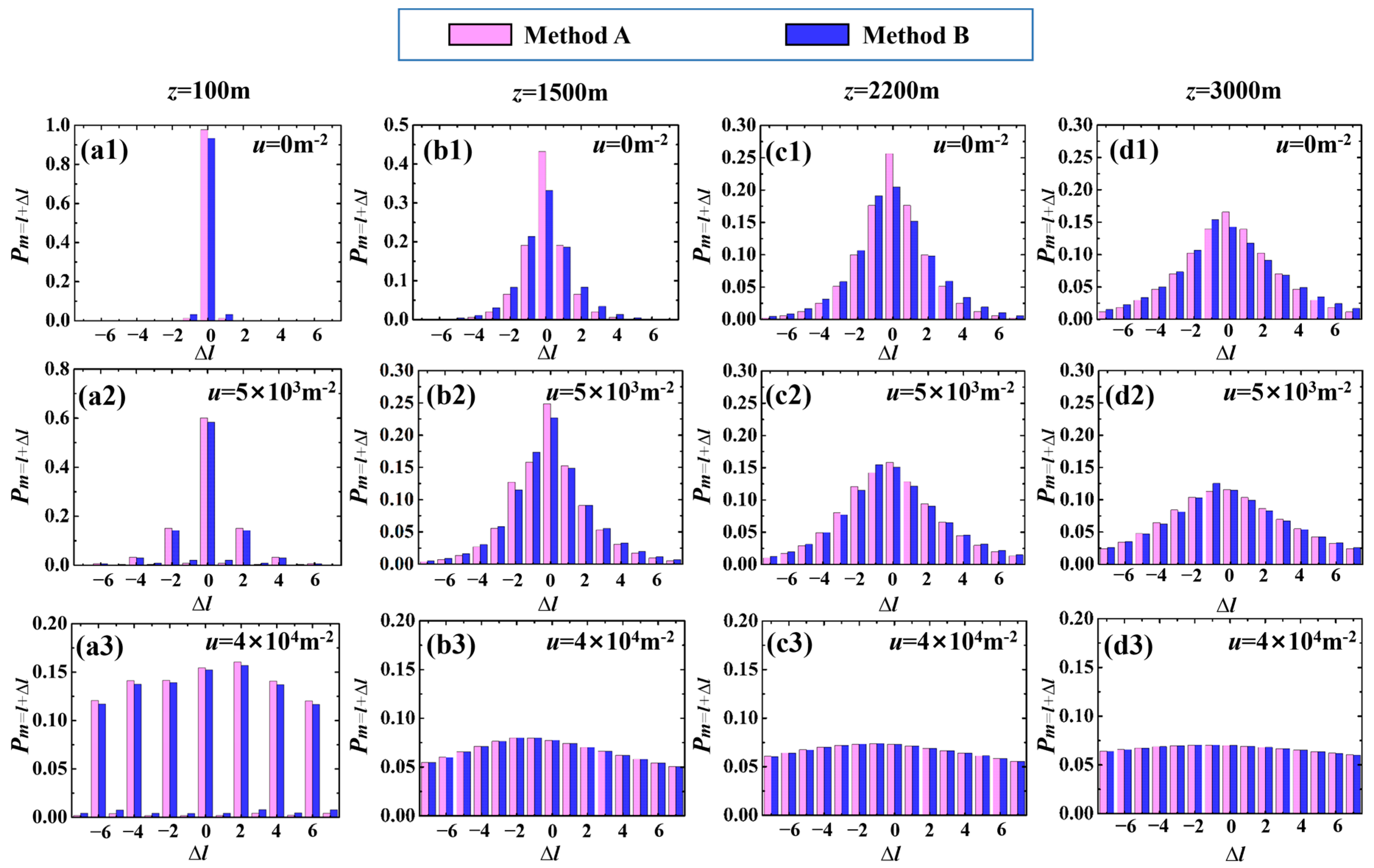
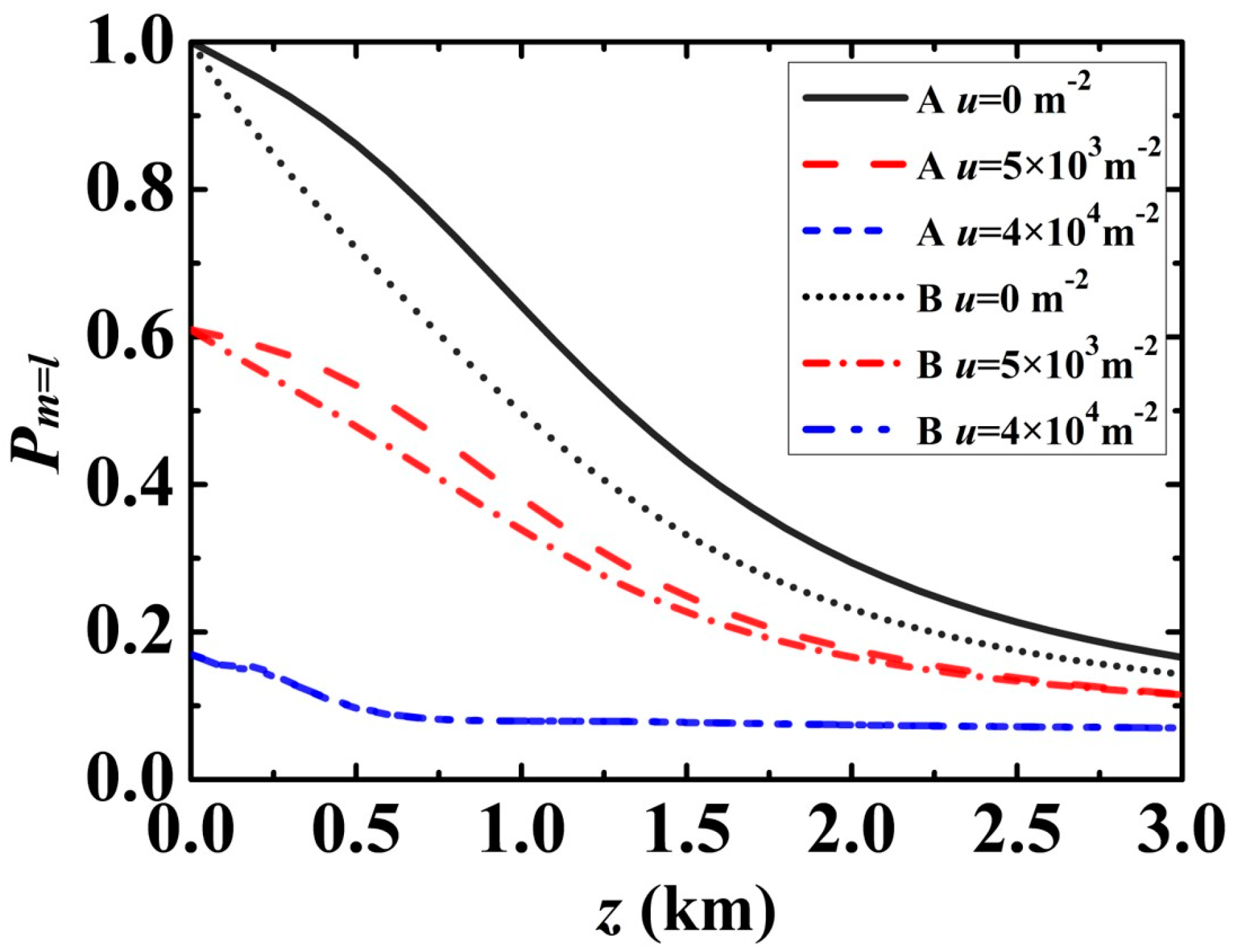
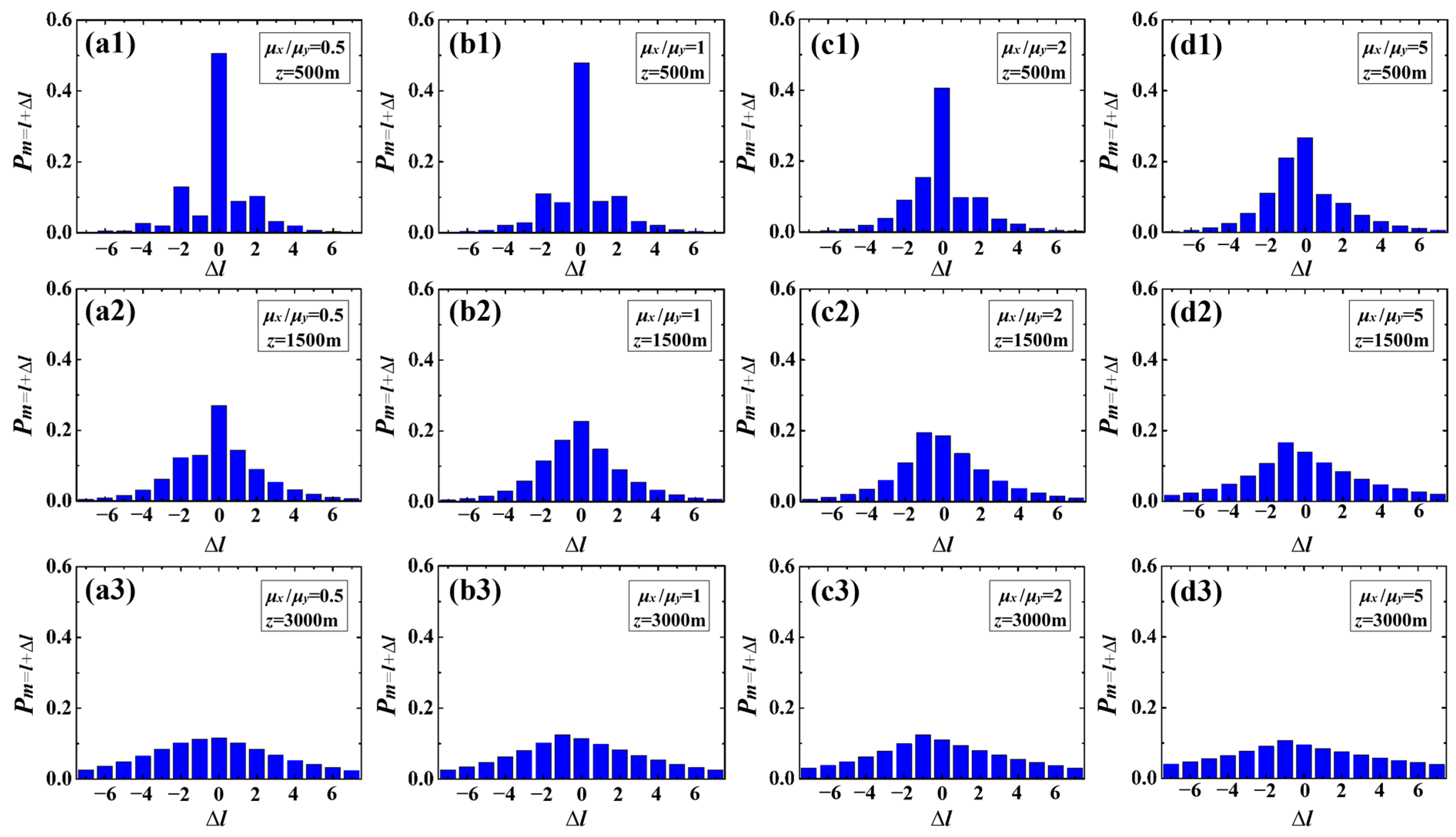
3.2. Spiral Spectrum of an LG Beam Carrying the Cross-Phase in Weak-to-Strong Anisotropic Atmospheric Turbulence

Next, we explored the behavior of the spiral spectrum of an LG beam carrying the cross-phase in isotropic and anisotropic turbulence (z > 0), respectively. The former requires the anisotropic factors of the turbulence to satisfy μx = μy = μz = 1. When dealing with the latter’s transmission, we focus on considering the anisotropy in the vertical direction (i.e., μxz ≠ μy) so that we only need to know the ratio of μx to μy to determine the values of all three factors with the help of the constrained condition of μxμyμz = 1. Here, we distinguish the strength of atmospheric turbulence based on the well-known Rytov variance  σ R 2 = 1.23 C n 2 k 7 / 6 z 11 / 7 , which represents the intensity scintillation index of a plane wave [51]. Weak fluctuations are associated with σ R 2 < 1 , moderate fluctuation conditions are characterized by σ R 2 1 , and strong fluctuations fall in the region of σ R 2 > 1 .
Figure 3 displays the spiral spectrum of an LG beam carrying the cross-phase with different factors u in a state of isotropic turbulence for different strengths of turbulence using the eHF method (Method B marked in blue). In comparison, the corresponding results calculated using the SPSP method (Method A marked in pink) are also illustrated. In our calculations, the Rytov variance σ R 2 = 1.23 C n 2 k 7 / 6 z 11 / 7 for z = 100 m, 1500 m, 2200 m and 3000 m are 0.003, 0.419, 0.845 and 1.492, respectively, ranging from weak to strong fluctuations. In the absence of the cross-phase (u = 0 m−2) and when the strength of turbulence is very weak σ R 2 ~0.003 (z = 100 m), the spiral spectrums obtained with the two calculation methods are symmetrical with respect to Pm=1 (i.e., Δl = 0) (see Figure 3(a1)). As the strength of turbulence increases (i.e., the propagation distance increases), the spectra obtained by Method B (blue histograms) become asymmetric (see Figure 3(b1–d1)), which is consistent with the experimental results reported by Ren et al. [53]. The energy spread on both sides with respect to Pm=1 (i.e., Δl = 0) is non-uniform, resulting in a mode weight Pm=0 (i.e., Δl = −1) greater than Pm=2 (i.e., Δl = 1). This phenomenon is quite different from that predicated by Method A (pink histograms), where the spectra are always symmetrical with respect to Pm=1 (i.e., Δl = 0). This implies that the discrepancies between the two methods gradually become apparent as the turbulence strength increases. The reason for this phenomenon is that Method B fully considers the interaction between turbulence and the OAM modes during the transmission process. In addition, it was found that regardless of the strength of the turbulence, as the cross-phase factor increases, the spiral spectrum is gradually regulated to a wide OAM spectrum containing multiple helical harmonic modes with equal intensity weights, i.e., an OAM comb (see Figure 3(a3–d3)). This means that increasing the cross-phase factor u can reduce the discrepancies between the two methods and show the ability of the cross-phase on the redistribution of energy. Meanwhile, with the increase in the strength of turbulence, the mode spacing of a modulated OAM comb changed from the original two (see Figure 3(a3)) to one (see Figure 3(d3)). This is because as the transmission distance increases, the perturbations caused by turbulence accumulate more strongly, resulting in more energy to spread to adjacent modes.
Figure 4 shows the variation in the central mode Pm=ll = 0) with the propagation distance z for different values of cross-phase factor u. The results of the numerical calculations obtained by the two methods (A and B) are displayed through different curves. As expected, in the absence of the cross-phase (u = 0 m−2), the values of Pm=l calculated by the single-phase screen perturbation propagation model are always larger than those via the use of the extended Huygens–Fresnel propagation model, irrespective of z. This is because the former does not consider the effect of turbulence on the OAM mode during propagation. It is also clearly shown that the difference between the results calculated by the two methods decreases as u increases. In particular, when u is large enough (e.g., u = 4 × 10⁴ m−2), the curves obtained with the two methods basically overlap (see blue curves). Moreover, with the increase in u, the falling range of central mode Pm=l caused by the increase in turbulence (increase in transmission distance) will gradually decrease. This is because the enhanced cross-phase effect will gradually distribute the total energy evenly to each mode.
We now investigate the influence of the anisotropic factors of turbulence on the spiral spectrum. The following calculation results are obtained based on the extended Huygens–Fresnel method. Figure 4 presents the changes in the spiral spectrum with the anisotropic condition μx/μy and propagation distance z. The cross-phase factor in the calculation is set as u = 5 × 10 3   m 2 . When the strength of the turbulence is weak (z = 500 m for σ R 2 = 0.0558), it can be seen that the anisotropic condition (the ratio of μx/μy) plays a certain role in determining the spiral spectrum distribution (see Figure 5(a1–d1)). The weight of each order mode will change significantly due to different anisotropic conditions. As the strength of turbulence (or the propagation distance) increases, the effect of the anisotropy condition on the OAM spectrum decreases, especially in strong turbulence, where the distribution of the OAM spectrum is almost unchanged for different anisotropic conditions (see Figure 5(a3–d3)). As a remarkable feature of this effect, it is approximately the same for different values of cross-phase. This was tested for values of the cross-phase ranging from u = 5 × 10 3   m 2 to u = 2 × 10 4   m 2 .
To further reveal the effect of cross-phase and anisotropic conditions on the central mode Pm=ll = 0) in anisotropic turbulence, in Figure 6, we show the variation in Pm=l with the propagation distance for different values of μx/μy and cross-phase factors u. In the absence of the cross-phase (u = 0 m−2), one can find that the central mode Pm=ll = 0) depends strongly on this ratio. As the ratio of μx/μy increases, Pm=l decreases. Due to the effect of the cross-phase, the difference in Pm=l under different anisotropic conditions has been significantly reduced (see Figure 6b). With a further increase in the cross-phase factor u (e.g., u = 4 × 10⁴ m−2), the mode weight Pm=l for different anisotropic cases become close to each other, especially in the case of moderate to strong turbulence (z > 2000 m), where the anisotropy hardly affects the mode weight Pm=l (see Figure 6c). This indicates that by modulating the cross-phase, the effects of the anisotropic factors of turbulence on the spiral spectrum can be weakened.
OAM detection underpins almost all aspects of the advances in vortex beams, such as communication. Although this paper is only a theoretical work, the direction of future experimental research can be envisioned as follows. To study the impact of a turbulent atmosphere on vortex beams, the first matter to deal with is the generation of the turbulence. One can consider using a hot plate [54,55] or random complex phase screens [31] to simulate the turbulent environment in the laboratory. The former can effectively achieve quantitative control over the strength of turbulence by adjusting the hotplate temperature (the specific quantitative relationship can be inverted using the scintillation index [54] or Fried’s coherence length [56]). The latter takes into account more turbulence parameters based on the adjustability of the hologram. Secondly, this research involves the measurement of the mutual coherence function. Since the mutual coherence function is a complex valued function of four scalar arguments, it is hard to directly obtain full information about it in an experiment. Fortunately, the proposal of the phase perturbation method [57,58] and generalized Arago spot experiment [59] provide possibilities for our future experimental research. In addition, the recently reported multi-mode ptychography technology [60] and intelligent optoelectronic processor [61] also provide more options for directly measuring the orbital angular momentum spiral spectrum distribution of OAM beams in turbulence.

4. Conclusions

In summary, we developed a theoretical model for calculating the spiral spectrum (OAM spectrum) of an LG beam carrying the cross-phase and propagating in isotropic and anisotropic Kolmogorov turbulence. The method makes use of the extended Huygens–Fresnel integral and is applicable to a wide range of turbulent flows from weak to strong. In the source plane, the OAM spiral spectrum of an LG beam carrying the cross-phase strictly depends on that cross-phase. As the value of the cross-phase factor increases, the distribution of the spiral spectrum is gradually expanded into a comb-like OAM spectrum. Compared with previous schemes to tailor the OAM spectrum, such as the pattern-search algorithm [37], mode iteration method [38] and use of pinhole plates [39], the cross-phase control scheme we have demonstrated is simpler and is expected to avoid long response or calculation times, complex systems and lower diffraction efficiency. Furthermore, based on the derived model, the specific impact of cross-phase and the strength of turbulence (i.e., the propagation distance) on the spiral spectrum have been investigated in isotropic turbulence using some numerical examples. As a comparison, the corresponding results calculated based on the single-phase screen perturbation method, which is the most widely used, are also presented. These two sets of results reveal that as turbulence increases, the differences between the results obtained by the two methods gradually become apparent. In particular, in moderate to strong turbulence, the symmetry of the spiral spectrum obtained based on the extended Huygens–Fresnel method is even destroyed. However, we were pleasantly surprised to find that the discrepancies between the calculation results of the two methods can be reduced through the choice of an appropriate cross-phase factor. Moreover, even in turbulence, the OAM comb spiral spectrum distribution obtained through cross-phase control can still be maintained, and its mode spacing will decrease due to the enhancement of turbulence. Finally, the effect of the anisotropic conditions of turbulence on the spiral spectrum is also analyzed. The results show that anisotropic conditions play a certain role in determining the distribution of the OAM spectrum, and increasing the cross-phase factor can effectively reduce the impact of anisotropy on the OAM spectrum. Our findings present a simple approach for OAM spectrum manipulation and may be helpful in a variety of OAM-based applications, such as free-space optical communications and data information transfer in anisotropic turbulence.

Supplementary Materials

The following supporting information can be downloaded at: https://www.mdpi.com/article/10.3390/photonics11020148/s1.

Author Contributions

Conceptualization, J.Z.; methodology, Y.L. and Z.Z.; software, Y.L. and H.Z.; validation, R.L.; investigation, R.L. and D.X.; data curation, Y.L. and J.Z.; writing—original draft preparation, Y.L. and J.Z.; writing—review and editing, J.Z.; supervision, Y.C. and J.Z.; project administration, J.Z.; funding acquisition, Y.C. and J.Z. All authors have read and agreed to the published version of the manuscript.

Funding

This research was funded by the National Key Research and Development Program of China (Grant Nos. 2022YFA1404800 and 2019YFA0705000), the National Natural Science Foundation of China (Grant Nos. 12104264, 12192254, 92250304), the Natural Science Foundation of Shandong Province (Grant No. ZR2021QA014) and the Qingchuang Science and Technology Plan of Shandong Province (Grant No. 2022KJ246).

Institutional Review Board Statement

Not applicable.

Informed Consent Statement

Not applicable.

Data Availability Statement

Data underlying the results presented in this paper are not publicly available at this time but may be obtained from the authors upon reasonable request.

Conflicts of Interest

The authors declare no conflicts of interest.

References

  1. Gbur, G. Singular Optics; CRC Press: Boca Raton, FL, USA, 2017. [Google Scholar]
  2. Allen, L.; Beijersbergen, M.W.; Spreeuw, R.J.C.; Woerdman, J.P. Orbital angular momentum of light and the transformation of Laguerre-Gaussian laser modes. Phys. Rev. A 1992, 11, 8185–8189. [Google Scholar] [CrossRef]
  3. Tamburini, F.; Anzolin, G.; Umbriaco, G.; Bianchini, A.; Barbieri, C. Overcoming the Rayleigh Criterion Limit with Optical Vortices. Phys. Rev. Lett. 2006, 97, 163903. [Google Scholar] [CrossRef]
  4. Qiu, X.; Li, F.; Zhang, W.; Zhu, Z.; Chen, L. Spiral phase contrast imaging in nonlinear optics: Seeing phase objects using invisible illumination. Optica 2018, 5, 208–212. [Google Scholar] [CrossRef]
  5. He, H.; Friese, M.E.; Heckenberg, N.R.; Rubinsztein-Dunlop, H. Direct observation of transfer of angular momentum to absorptive particles from a laser beam with a phase singularity. Phys. Rev. Lett. 1995, 75, 826–829. [Google Scholar] [CrossRef]
  6. Paterson, L.; MacDonald, M.P.; Arlt, J.; Sibbett, W.; Bryant, P.E.; Dholakia, K. Controlled rotation of optically trapped microscopic particles. Science 2001, 292, 912–914. [Google Scholar] [CrossRef] [PubMed]
  7. Yang, Y.; Ren, Y.; Chen, M.; Arita, Y.; Rosales-Guzmán, C. Optical trapping with structured light: A review. Adv. Photonics 2021, 3, 034001. [Google Scholar] [CrossRef]
  8. Fang, X.; Ren, H.; Gu, M. Orbital angular momentum holography for high-security encryption. Nat. Photonics 2020, 14, 102–108. [Google Scholar] [CrossRef]
  9. Kong, L.; Zhang, W.; Li, P.; Guo, X.; Zhang, J.; Zhang, F.; Zhao, J.; Zhang, X. High capacity topological coding based on nested vortex knots and links. Nat. Commun. 2022, 13, 2705. [Google Scholar] [CrossRef] [PubMed]
  10. Wen, Y.; Chremmos, I.; Chen, Y.; Zhang, Y.; Yu, S. Arbitrary Multiplication and Division of the Orbital Angular Momentum of Light. Phys. Rev. Lett. 2020, 124, 213901. [Google Scholar] [CrossRef] [PubMed]
  11. Lavery, M.P.J.; Speirits, F.C.; Barnett, S.M.; Padgett, M.J. Detection of a spinning object using light’s orbital angular momentum. Science 2013, 341, 537–540. [Google Scholar] [CrossRef] [PubMed]
  12. Ren, Y.; Wang, Z.; Liao, P.; Li, L.; Xie, G.; Huang, H.; Zhao, Z.; Yan, Y.; Ahmed, N.; Willner, A.; et al. Experimental characterization of a 400 Gbit/s orbital angular momentum multiplexed free-space optical link over 120 m. Opt. Lett. 2016, 41, 622–625. [Google Scholar] [CrossRef]
  13. Wang, A.; Zhu, L.; Wang, L.; Ai, J.; Chen, S.; Wang, J. Directly using 8.8-km conventional multi-mode fiber for 6-mode orbital angular momentum multiplexing transmission. Opt. Express 2018, 26, 10038–10047. [Google Scholar] [CrossRef]
  14. Willner, A.E.; Huang, H.; Yan, Y.; Ren, Y.; Ahmed, N.; Xie, G.; Bao, C.; Li, L.; Cao, Y.; Zhao, Z.; et al. Optical communications using orbital angular momentum beams. Adv. Opt. Photon. 2015, 7, 66–106. [Google Scholar] [CrossRef]
  15. Shen, Y.; Wang, X.; Xie, Z.; Min, C.; Fu, X.; Liu, Q.; Gong, M.; Yuan, X. Optical vortices 30 years on: OAM manipulation from topological charge to multiple singularities. Light Sci. Appl. 2019, 8, 90. [Google Scholar] [CrossRef]
  16. Wang, J.; Yang, J.; Fazal, I.M.; Ahmed, N.; Yan, Y.; Huang, H.; Ren, Y.; Yue, Y.; Dolinar, S.; Tur, M.; et al. Terabit free-space data transmission employing orbital angular momentum multiplexing. Nat. Photonics 2012, 6, 488–496. [Google Scholar] [CrossRef]
  17. Yan, Y.; Xie, G.; Lavery, M.P.J.; Huang, H.; Ahmed, N.; Bao, C.; Ren, Y.; Cao, Y.; Li, L.; Zhao, Z.; et al. High-capacity millimetre-wave communications with orbital angular momentum multiplexing. Nat. Commun. 2014, 5, 4876. [Google Scholar] [CrossRef]
  18. Lei, T.; Zhang, M.; Li, Y.; Jia, P.; Liu, G.N.; Xu, X.; Li, Z.; Min, C.; Lin, J.; Yu, C.; et al. Massive individual orbital angular momentum channels for multiplexing enabled by Dammann gratings. Light Sci. Appl. 2015, 4, e257. [Google Scholar] [CrossRef]
  19. Wang, J.; Liu, J.; Li, S.; Zhao, Y.; Du, J.; Zhu, L. Orbital angular momentum and beyond in free-space optical communications. Nanophotonics 2022, 11, 645–680. [Google Scholar] [CrossRef]
  20. Paterson, C. Atmospheric turbulence and orbital angular momentum of single photons for optical communication. Phys. Rev. Lett. 2005, 94, 153901. [Google Scholar] [CrossRef] [PubMed]
  21. Anguita, J.A.; Neifeld, M.A.; Vasic, B.V. Turbulence-induced channel crosstalk in an orbital angular momentum-multiplexed free-space optical link. Appl. Opt. 2008, 47, 2414–2429. [Google Scholar] [CrossRef] [PubMed]
  22. Tyler, G.A.; Boyd, R.W. Influence of atmospheric turbulence on the propagation of quantum states of light carrying orbital angular momentum. Opt. Lett. 2009, 34, 142–144. [Google Scholar] [CrossRef] [PubMed]
  23. Yang, D.; Hu, Z.; Wang, S.; Zhu, Y. Influence of random media on orbital angular momentum quantum states of optical vortex beams. Phys. Rev. A 2022, 105, 053513. [Google Scholar] [CrossRef]
  24. Jiang, Y.; Wang, S.; Zhang, J.; Ou, J.; Tang, H. Spiral spectrum of Laguerre–Gaussian beam propagation in non-Kolmogorov turbulence. Opt. Commun. 2013, 303, 38–41. [Google Scholar] [CrossRef]
  25. Yu, L.; Hu, B.; Zhang, Y. Intensity of vortex modes carried by Lommel beam in weak-to-strong non-Kolmogorov turbulence. Opt. Express 2017, 25, 19538. [Google Scholar] [CrossRef]
  26. Zeng, J.; Liu, X.; Zhao, C.; Wang, F.; Gbur, G.; Cai, Y. Spiral spectrum of a Laguerre-Gaussian beam propagating in anisotropic non-Kolmogorov turbulent atmosphere along horizontal path. Opt. Express 2019, 27, 25342–25356. [Google Scholar] [CrossRef]
  27. Li, P.; Liu, S.; Peng, T.; Xie, G.; Gan, X.; Zhao, J. Spiral autofocusing Airy beams carrying power-exponent-phase vortices. Opt. Express 2014, 22, 7598. [Google Scholar] [CrossRef]
  28. Wang, Y.; Bai, L.; Xie, J.; Zhang, D.; Lv, Q.; Guo, L. Spiral spectrum of high-order elliptic Gaussian vortex beams in a non-Kolmogorov turbulent atmosphere. Opt. Express 2021, 29, 16056. [Google Scholar] [CrossRef]
  29. Zhu, Y.; Liu, X.; Gao, J.; Zhang, Y.; Zhao, F. Probability density of the orbital angular momentum mode of Hankel-Bessel beams in an atmospheric turbulence. Opt. Express 2014, 22, 7765. [Google Scholar] [CrossRef]
  30. Chen, C.; Yang, H.; Tong, S.; Lou, Y. Changes in orbital-angular-momentum modes of a propagated vortex Gaussian beam through weak-to-strong atmospheric turbulence. Opt. Express 2016, 24, 6959–6975. [Google Scholar] [CrossRef]
  31. Fu, S.; Gao, C. Influences of atmospheric turbulence effects on the orbital angular momentum spectra of vortex beams. Photonics Res. 2016, 4, 1–4. [Google Scholar] [CrossRef]
  32. Elder, H.F.; Sprangle, P. Mode power spectrum for Laguerre–Gauss beams in Kolmogorov turbulence. Opt. Lett. 2022, 47, 3447–3450. [Google Scholar] [CrossRef]
  33. Chen, C.; Yang, H. Characterizing the radial content of orbital-angular-momentum photonic states impaired by weak-to-strong atmospheric turbulence. Opt. Express 2016, 24, 19713–19727. [Google Scholar] [CrossRef]
  34. Lv, H.; Ren, C.; Liu, X. Orbital angular momentum spectrum of partially coherent vortex beams in slant atmospheric turbulence. Infrared Phys. Technol. 2020, 105, 103181. [Google Scholar] [CrossRef]
  35. Zhao, Y.; Xu, J.; Wang, A.; Lv, W.; Zhu, L.; Li, S.; Wang, J. Demonstration of data-carrying orbital angular momentum-based underwater wireless optical multicasting link. Opt. Express 2017, 25, 28743–28751. [Google Scholar] [CrossRef]
  36. Fang, X.; Yang, H.; Yao, W.; Wang, T.; Zhang, Y.; Gu, M.; Xiao, M. High-dimensional orbital angular momentum multiplexing nonlinear holography. Adv. Photonics 2021, 3, 015001. [Google Scholar] [CrossRef]
  37. Zhu, L.; Wang, J. Simultaneous generation of multiple orbital angular momentum (OAM) modes using a single phase-only element. Opt. Express 2015, 23, 26221–26233. [Google Scholar] [CrossRef] [PubMed]
  38. Lin, J.; Yuan, X.C.; Tao, S.H.; Burge, R.E. Collinear superposition of multiple helical beams generated by a single azimuthally modulated phase-only element. Opt. Lett. 2005, 30, 3266–3268. [Google Scholar] [CrossRef] [PubMed]
  39. Yang, Y.; Zhao, Q.; Liu, L.; Liu, Y.; Rosales-Guzmán, C.; Qiu, C. Manipulation of Orbital-Angular-Momentum Spectrum Using Pinhole Plates. Phys. Rev. Appl. 2019, 12, 064007. [Google Scholar] [CrossRef]
  40. Fu, S.; Shang, Z.; Hai, L.; Huang, L.; Lv, Y.; Gao, C. Orbital angular momentum comb generation from azimuthal binary phases. Adv. Photonics Nexus 2022, 1, 016003. [Google Scholar] [CrossRef]
  41. Liang, G.; Wang, Q. Controllable conversion between Hermite Gaussian and Laguerre Gaussian modes due to cross phase. Opt. Express 2019, 27, 10684–10691. [Google Scholar] [CrossRef]
  42. Wan, L.; Zhao, D. Controllable rotating Gaussian Schell-model beams. Opt. Lett. 2019, 44, 735–738. [Google Scholar] [CrossRef] [PubMed]
  43. Ren, Y.; Wang, C.; Liu, T.; Wang, Z.; Yin, C.; Qiu, S.; Li, Z.; Wu, H. Polygonal shaping and multi-singularity manipulation of optical vortices via high-order cross-phase. Opt. Express 2020, 28, 26257–26266. [Google Scholar] [CrossRef] [PubMed]
  44. Liu, X.; Li, Z.; Monfared, Y.E.; Liang, C.; Wang, F.; Hoenders, B.J.; Cai, Y.; Ma, P. Flexible autofocusing properties of ring Pearcey beams by means of a cross phase. Opt. Lett. 2021, 46, 70–73. [Google Scholar]
  45. Simon, R.; Mukunda, N. Twist phase in Gaussian-beam optics. J. Opt. Soc. Am. A 1998, 15, 2373–2382. [Google Scholar] [CrossRef]
  46. Liu, Y.; Chen, Y.; Wang, F.; Cai, Y.; Liang, C.; Korotkova, O. Robust far-field imaging by spatial coherence engineering. Opto-Electron. Adv. 2021, 4, 210027. [Google Scholar] [CrossRef]
  47. Klug, A.; Peters, C.; Forbes, A. Robust structured light in atmospheric turbulence. Adv. Photonics 2023, 5, 016006. [Google Scholar] [CrossRef]
  48. Diouf, M.; Lin, Z.; Harling, M.; Krishna, K.; Toussaint, K.C. Interferometric phase stability from Gaussian and space–time light sheets. Optica 2023, 10, 1161. [Google Scholar] [CrossRef]
  49. Diouf, M.; Lin, Z.; Harling, M.; Toussaint, K.C. Demonstration of speckle resistance using space–time light sheets. Sci. Rep. 2022, 12, 14064. [Google Scholar] [CrossRef]
  50. Yura, H.T. Mutual Coherence Function of a Finite Cross Section Optical Beam Propagating in a Turbulent Medium. Appl. Opt. 1972, 11, 1399–1406. [Google Scholar] [CrossRef]
  51. Andrews, L.C.; Phillips, R.L. Laser Beam Propagation through Random Media; SPIE Press: Bellingham, WA, USA, 2005. [Google Scholar]
  52. Peng, D.; Huang, Z.; Liu, Y.; Chen, Y.; Wang, F.; Ponomarenko, S.A.; Cai, Y. Optical coherence encryption with structured random light. PhotoniX 2021, 2, 6. [Google Scholar] [CrossRef]
  53. Ren, Y.; Huang, H.; Xie, G.; Ahmed, N.; Yan, Y.; Erkmen, B.I.; Chandrasekaran, N.; Lavery, M.P.; Steinhoff, N.K.; Tur, M.; et al. Atmospheric turbulence effects on the performance of a free space optical link employing orbital angular momentum multiplexing. Opt. Lett. 2013, 38, 4062–4065. [Google Scholar] [CrossRef]
  54. Zhu, Z.; Janasik, M.; Fyffe, A.; Hay, D.; Zhou, Y.; Kantor, B.; Winder, T.; Boyd, R.W.; Leuchs, G.; Shi, Z. Compensation-free high-dimensional free-space optical communication using turbulence-resilient vector beams. Nat. Commun. 2021, 12, 1666. [Google Scholar] [CrossRef] [PubMed]
  55. Zhang, Z.; Li, G.; Liu, Y.; Wang, H.; Hoenders B., J.; Liang, C.; Cai, Y.; Zeng, J. Robust measurement of orbital angular momentum of a partially coherent vortex beam under amplitude and phase perturbations. Opto-Electron. Sci. 2024, 3, 240001. [Google Scholar] [CrossRef]
  56. Vallone, G.; D’Ambrosio, V.; Sponselli, A.; Slussarenko, S.; Marrucci, L.; Sciarrino, F.; Villoresi, P. Free-space quantum key distribution by rotation-invariant twisted photons. Phys. Rev. Lett. 2014, 113, 060503. [Google Scholar] [CrossRef] [PubMed]
  57. Zeng, J.; Lu, X.; Liu, L.; Zhu, X.; Zhao, C.; Cai, Y. Simultaneous measurement of the radial and azimuthal mode indices of a higher-order partially coherent vortex beam based on phase detection. Opt. Lett. 2019, 44, 3881–3884. [Google Scholar] [CrossRef]
  58. Lu, X.; Zhao, C.L.; Shao, Y.; Zeng, J.; Konijnenberg, A.P.; Zhu, X.; Popov, S.; Urbach, P.; Cai, Y. Phase detection of coherence singularities and determination of the topological charge of a partially coherent vortex beam. Appl. Phys. Lett. 2019, 114, 201106. [Google Scholar] [CrossRef]
  59. Liu, X.; Chen, Q.; Zeng, J.; Cai, Y.; Liang, C. Measurement of optical coherence structures of random optical fields using generalized Arago spot experiment. Opto-Electron. Sci. 2023, 2, 220024. [Google Scholar] [CrossRef]
  60. Wang, Z.; Lu, X.; Gao, J.; Zhao, X.; Zhan, Q.; Cai, Y.; Zhao, C. Coherence phase spectrum analyzer for a randomly fluctuated fractional vortex beam. Photonics Res. 2024, 12, 33. [Google Scholar] [CrossRef]
  61. Wang, H.; Zhan, Z.; Hu, F.; Meng, Y.; Liu, Z.; Fu, X.; Liu, Q. Intelligent optoelectronic processor for orbital angular momentum spectrum measurement. PhotoniX 2023, 4, 9. [Google Scholar] [CrossRef]
Figure 1. Schematic diagram of (a) the single-phase screen perturbation method propagation system and (b) the extended Huygens–Fresnel method propagation system. (c,d) Schematic for the Kolmogorov cascade theory of turbulence. (c) Isotropic turbulence. (d) Anisotropic turbulence. L0 and l0 denote the outer and inner scales of turbulence, respectively. Turbulent cells (eddies) between the scale size L0 and l0 form the inertial subrange. r, Ra, Rb and Rc denote the semi-principal axes of turbulent cells in different directions, respectively.
Photonics 11 00148 g001
Figure 2. The effect of the cross-phase on the spiral spectrum and of an LG beam in the source plane. (a) u = 0 m−2; (b) u = 5 × 10³ m−2; (c) u = 4 × 10⁴ m−2; (d) u = 5 × 10⁴ m−2.
Photonics 11 00148 g002
Figure 3. Spiral spectrum of an LG beam carrying the cross-phase with different factors u in weak-to-strong isotropic turbulence (μx = μy = μz = 1) using different propagation models. Method A corresponds to the single-phase screen perturbation (SPSP) propagation model; Method B corresponds to the extended Huygens–Fresnel (eHF) propagation model. (a1d1) u = 0 m−2; (a2d2) u = 5 × 10³ m−2; (a3d3) u = 4 × 10⁴ m−2.
Photonics 11 00148 g003
Figure 4. Variation in Pm=l of an LG beam carrying the cross-phase with different factors u in isotropic turbulence (μx = μy = μz = 1) as a function of propagation distance z. A: single-phase screen perturbation propagation model; B: extended Huygens–Fresnel propagation model.
Photonics 11 00148 g004
Figure 5. Spiral spectrum of an LG beam carrying the cross-phase in anisotropic turbulence with different values of μx/μy for u = 5 × 10³ m−2. (a1d1) z = 500 m; (a2d2) z = 1500 m; (a3d3) z = 3000 m.
Photonics 11 00148 g005
Figure 6. Variation in Pm=l of an LG beam carrying the cross-phase with different factors u in anisotropic turbulence with different values of μx/μy as a function of propagation distance z. (a) u = 0 m−2; (b) u = 5 × 10³ m−2; (c) u = 4 × 10⁴ m−2.
Photonics 11 00148 g006
Disclaimer/Publisher’s Note: The statements, opinions and data contained in all publications are solely those of the individual author(s) and contributor(s) and not of MDPI and/or the editor(s). MDPI and/or the editor(s) disclaim responsibility for any injury to people or property resulting from any ideas, methods, instructions or products referred to in the content.

