Review

Display Field Communication: Enabling Seamless Data Exchange in Screen–Camera Environments

1
Department of Electronic Engineering, Yeungnam University, Gyeongsan 38541, Republic of Korea
2
Department of Information and Communication Engineering, Changwon National University, Changwon 51140, Republic of Korea
*
Authors to whom correspondence should be addressed.
Photonics 2024, 11(11), 1000; https://doi.org/10.3390/photonics11111000
Submission received: 23 August 2024 / Revised: 14 October 2024 / Accepted: 18 October 2024 / Published: 24 October 2024
(This article belongs to the Special Issue Novel Advances in Optical Communications)

Abstract

:
Display field communication (DFC) is an emerging technology that enables seamless communication between electronic displays and cameras. It utilizes the frequency-domain characteristics of image frames to embed and transmit data, which are then decoded and interpreted by a camera. DFC offers a novel solution for screen-to-camera data communication, leveraging existing displays and camera infrastructures. This makes it a cost-effective and easily deployable solution. DFC can be applied in various fields, including secure data transfer, mobile payments, and interactive advertising, where data can be exchanged by simply pointing a camera at a screen. This article provides a comprehensive survey of DFC, highlighting significant milestones achieved in recent years and discussing future challenges in establishing a fully functional DFC system. We begin by introducing the broader topic of screen–camera communication (SCC), classifying it into visible and hidden SCC. DFC, a type of spectral-domain hidden SCC, is then explored in detail. Various DFC variants are introduced, with a focus on the physical layer. Finally, we present promising experimental results from our lab and outline further research directions and challenges.

1. Introduction

Visible light communication (VLC) [1,2,3] refers to a method of data transmission that uses light waves within the visible spectrum, ranging from 380 nm to 750 nm. A key feature of this communication method is its ability to transfer data unobtrusively, without affecting the perceived illumination of the environment. VLC stands out from other wireless communication methods for several reasons. First, the growing demand for mobile data over the past two decades has revealed the limitations of relying solely on radio frequency (RF) communication, as the RF spectrum has become increasingly scarce. In contrast, the visible light spectrum offers hundreds of terahertz of license-free bandwidth, which remains largely untapped for communication purposes. VLC can complement RF-based systems, contributing to the creation of high-capacity mobile data networks. Secondly, the high frequency of visible light prevents it from penetrating most objects and walls, allowing for interference-free small cells of LED transmitters. This feature not only boosts wireless channel capacity but also enhances the security of communications. Finally, VLC’s ability to leverage existing lighting infrastructure makes system deployment easy and cost-effective. There are various applications of VLC in the context of 6G and beyond, having versatility across different environments. For indoor communication, VLC supports applications such as screen–camera communication (SCC), indoor localization, and human–computer interaction, enabling hands-free control of devices or systems. In outdoor scenarios, key applications include vehicular and underwater communication. Additionally, emerging technologies such as the Internet of Things (IoT) [4] and simultaneous lightwave information and power transfer (SLIPT) [5] are crucial for 6G networks. VLC, when integrated with IoT, provides reliable uplink and high-speed downlink communication using energy-efficient methods, even in low-light conditions. This makes it ideal for operating zero-energy devices without the need for battery replacements. SLIPT further enhances VLC by combining data transmission with energy harvesting, enabling simultaneous power and information transfer in indoor, underwater, and aerial environments. This makes it highly applicable to IoT devices, smart cities, and vehicular communication systems. In this study, we will review a particularly promising application and research area of VLC, namely, SCC.
SCC is a specialized application of VLC, where an LCD/LED screen and a camera sensor facilitate device-to-device (D2D) communication. SCC represents an innovative intersection of optical communication and digital technology, leveraging the widespread presence of screens and cameras in modern devices to enable a novel form of data transmission. The global proliferation of mobile devices, including smartphones, tablets, and sensors, has surged in recent years, making these devices an integral part of daily life. Their increasing capabilities are driven by the growing demand for constant connectivity and uninterrupted sensing abilities. SCC involves transmitting information from a digital screen (such as those on smartphones, tablets, televisions, and computer monitors) to a camera-equipped device (like smartphones, tablets, and wearables) using visual codes or modulations.
In the 1970s, barcodes were introduced to encode information that could be scanned and decoded using optical readers. Displaying a barcode on a screen allowed it to be captured by a camera-based scanner, enabling data transfer from screen to camera. QR codes, a more versatile form of two-dimensional barcodes, were invented in the 1990s and gained widespread popularity after the 2010s. By displaying a QR code on a screen and capturing it with a camera-equipped device [6], users could access URLs, store contact information, and perform various interactive tasks. However, dedicated communication channels for data transfer between devices face limitations, such as the need for additional hardware and interference with user experience. Additionally, QR codes can only transfer limited amounts of data and often create visual obstructions that detract from the aesthetic appeal (cf., Figure 1). Unlike barcodes and QR codes, which are static information retrieval systems, SCC has evolved into a dynamic communication system that enables real-time data exchange between devices.
The advent of smartphones and their integrated cameras marked a major turning point in the development of SCC. As smartphones became ubiquitous, the ability to capture and process visual information expanded. Researchers and developers have since explored various techniques to enhance SCC, including the use of specific color patterns, specialized markers, and computer vision algorithms to improve the accuracy and reliability of data transfer between displays and cameras [7,8]. Moreover, recent trends in increasing screen resolution and camera quality, combined with advances in digital signal processing and computer vision algorithms, have enabled more sophisticated and unobtrusive methods of data transmission. These include the use of imperceptible modulations in displayed images or videos, which cameras can seamlessly decode. One pivotal advancement in SCC development was recognizing that it could facilitate a wide range of applications beyond simple information retrieval from static codes, such as interactive advertising, secure authentication, augmented reality (AR), and smart device connectivity.
In this review, we provide a comprehensive overview of SCC research, highlighting key challenges that warrant further investigation. Our analysis specifically covers the following:
  • A detailed examination of SCC system components, including the characteristics of transmitters and receivers.
  • An exploration of the physical layer, including display-to-camera (D2C) channel models, signal propagation, and modulation with coding strategies.
  • An in-depth survey on display field communication (DFC), a spectral-domain-based SCC scheme.
  • DFC system architecture and signal processing aspects.
  • Comparisons of various SCC and DFC schemes.
  • State of the art in DFC, challenges, and future direction.
Although significant progress has been made in SCC over the past few decades, no comprehensive surveys on SCC currently exist to the best of our knowledge. A major portion of this manuscript focuses on DFC [9], an innovative hidden SCC method proposed by our lab that enables unobtrusive data transfer between electronic displays and cameras. Leveraging concepts from two-dimensional orthogonal frequency division multiplexing (2D-OFDM) [10], we describe different versions of DFC and compare achievable data rates (ADRs). Additionally, we present a practical implementation of DFC, incorporating machine learning (ML) concepts.
The structure of this paper is as follows. Section 2 describes the fundamentals of the human vision system (HVS) and its similarities to a camera. Since SCC is a type of optical camera communication (OCC), we also cover the basics of camera image capturing. Section 3 outlines the SCC system architecture, including the transmitter, receiver, and applications. 
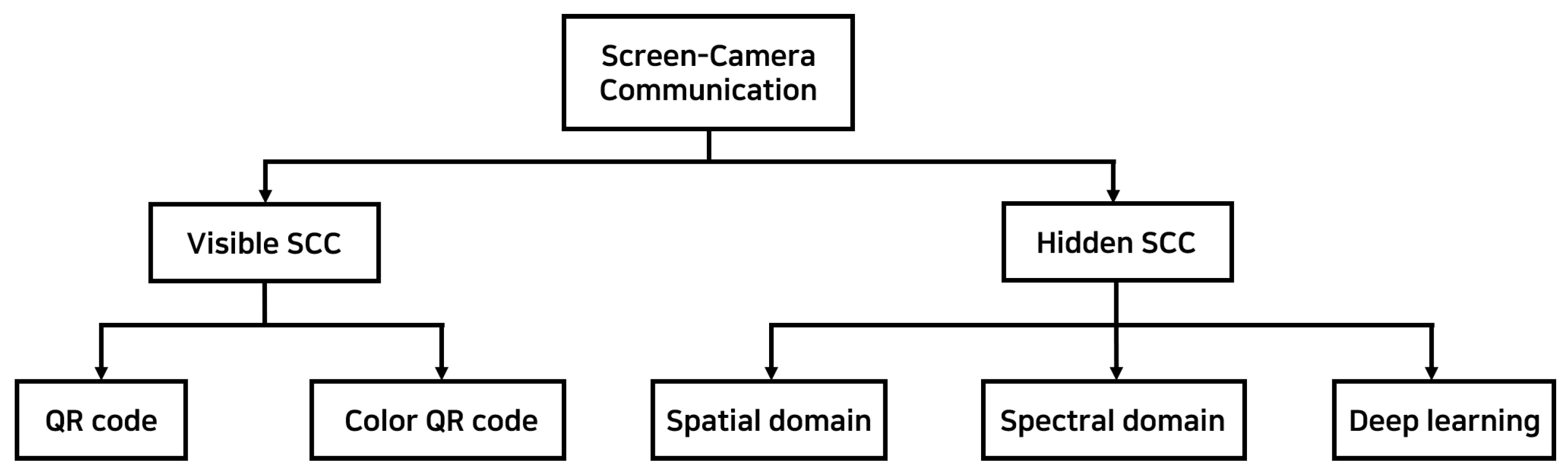
Section 4 broadly classifies SCC into visible and hidden types and explains fundamental theories with references to related works. In Section 5, we delve into the specific topic of DFC, detailing its design and operation. We explain the system model, the various DFC variants, and the coding and decoding processes, including ML and channel coding parts. Section 6 presents the signal processing aspects of DFC, especially at the physical layer. This includes frequency conversion, modulation, data embedding, channel coding, and data decoding strategies. Section 7 compares the performances of multiple DFC forms within a common framework of ADR, including experimental DFC results. Section 8 and Section 9 conclude the paper, discussing recent trends, challenges, and future directions.

2. Human Vision System (HVS)

Before diving into the survey of SCC and signal processing aspects, it is important to understand the working of the HVS and the capabilities of modern displays and cameras. The HVS is responsible for capturing information about object shapes, colors, depth, and motion. Vision serves as the primary mechanism through which humans acquire information. The HVS is both sophisticated and complex [11,
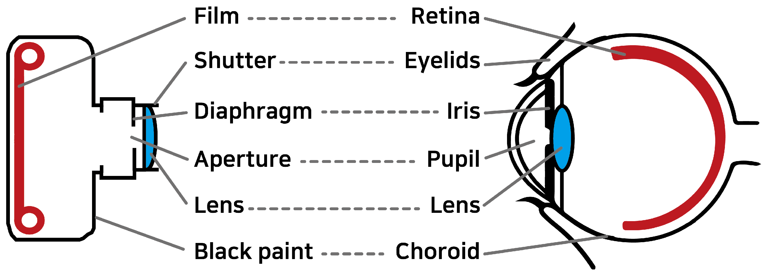
12]. At the core of the HVS are the eyes, which respond to light. As shown in Figure 2, the structure of a camera bears a resemblance to that of the eye [13], featuring a lens (the crystalline lens) and a sensor surface (the retina). The density of receptor cells on the retina is higher in the center and gradually decreases toward the edges, giving rise to central (or foveal) vision and peripheral vision. Central vision is crucial for detailed visual processing, while peripheral vision, rich in light-sensitive rod cells, excels in motion detection and performs better under low-light conditions.
While the eyes provide a wealth of information about the physical environment, they also have inherent limitations in both spatial and temporal resolution. The human eye’s ability to discern fine details is limited by the spacing between adjacent receptor cells on the retina. Typically, the finest spatial resolution achievable by the human eyes is 0.07°, which equates to 1.2 mm at a distance of 1 m [14]. This resolution varies with spatial contrast, and the eye’s receptive field responds differently at its center compared to its periphery, depending on the spatial frequency. Our spatial perception exhibits bandpass (or near-low-pass) characteristics, with the highest frequency around 2–4 cycles per visual angle. As a result, exceedingly small details may blend into an average appearance. This effect is evident during vision tests, where details beyond the eye’s resolution appear as vague shapes. Light intensity variations become indiscernible when they exceed a certain threshold, known as the critical flicker frequency (CFF) [15]. Beyond this frequency, the human eye perceives only an average luminance, similar to the response of a linear low-pass filter to high frequencies. For instance, a rapidly rotating car wheel may appear semi-transparent. The CFF is influenced by various factors such as color contrast and luminance waveforms, typically ranging from 40 to 50 Hz [16,17]. This explains why flicker from a 60 Hz monitor is generally not noticeable.
A notable distinction between the human eye and a camera is the absence of a shutter in the eye, meaning that there is no exposure process or perception of images in discrete frames. In contrast, cameras capture discrete snapshots, allowing for detailed inspection of each frame. While the HVS excels in many respects, camera technology has already surpassed it in certain aspects, particularly in spatial and temporal resolution. The unique characteristics of the HVS, combined with the expanding gap in capabilities due to rapid advancements in camera technology, present significant opportunities for innovative design. Since the HVS has remained relatively unchanged over time while camera technologies have evolved rapidly, this gap—and the innovation potential—will only continue to grow in the future.
Modern displays, especially high-refresh-rate monitors, are becoming increasingly popular. Most standard monitors have a refresh rate of 60 Hz , which means they can display up to 60 frames per second. However, monitors with higher refresh rates, such as 144 Hz , 240 Hz , or even 360 Hz , are now commercially available. Additionally, many smartphones are equipped with advanced cameras capable of high-frame-rate video capturing. These devices typically support video resolutions up to 8K and can capture footage at various frame rates, such as 4 K at 60 fps, 1080 p at 240 fps, and even super slow-motion video at 720 p up to 960 fps. These features make them highly versatile for SCC. When transmitting data-embedded frames at a refresh rate of at least 60 Hz, the human eye perceives only the average values due to the low-pass filtering effect. However, as we will see later, DFC can embed data in frames with minimal visual disparity from the original, making the changes imperceptible to the human eye, even at low frame rates [9].

3. SCC System Architecture

A typical SCC system is designed to facilitate data transmission through visual channels, with a screen serving as the transmitter and a camera-equipped device as the receiver. In this section, we provide an overview of the SCC system and its modes of communication. While SCC can involve different types of communications, this survey focuses primarily on SCC systems where an LCD/LED screen functions as the transmitter, transmitting data through visual image frames.

3.1. SCC Transmitter

The transmitter in an SCC system is any device capable of displaying visual information, such as smartphones, tablets, digital signage, and LEDs or LCDs. A digital display is a complex unit consisting of multiple pixels that can be individually controlled to present images, videos, or specific patterns. These pixels, composed of red (R), green (G), and blue (B) sub-pixels, enable precise control of color and brightness across the display surface. In the SCC transmitter, the pixel matrix of the display is used to encode and transmit data by modulating visual patterns or light intensity, which can be captured by a camera-equipped receiver. This modulation can involve altering the brightness, color, or pattern of the pixels to encode the data. The adaptation of existing display technology for SCC purposes has led to innovative techniques that ensure efficient data transmission without affecting display performance. For example, CDMA-like modulation techniques [11,12] can encode data within the normal operation of the display, taking advantage of the high resolution and rapid refresh rates of modern screens to transmit data within the displayed content.

3.2. SCC Receiver

There are two primary types of receivers used in SCC systems to capture and decode signals transmitted via display screens:
  • Standard camera—typically integrated into mobile devices.
  • Advanced imaging sensors—including high-speed or specialized cameras used for research or industrial applications.
A standard camera in mobile devices serves as the core component of an SCC receiver. These cameras, equipped with advanced image sensors, can capture high-resolution images and videos, enabling them to detect and decode the modulated data embedded in the screen’s visual output. Modern mobile device cameras can sample visual signals at varying frame rates, making them readily available for SCC reception. Advanced imaging sensors or high-speed cameras provide enhanced capabilities, offering significantly higher frame rates. These sensors are designed to capture rapid temporal variations in visual signals, enabling more complex or high-speed SCC applications. Although less common than mobile device cameras, these specialized sensors can achieve higher data rates and more precise signal detection.
One of the primary challenges for SCC receivers, particularly standard cameras, is balancing high-resolution capture with fast signal processing. The spatial resolution of the camera sensor, determined by the number of photodetectors (pixels), directly affects its ability to resolve fine details in the transmitted signal. However, higher resolutions often come at the cost of lower maximum frame rates due to the increased data volume per frame, which can limit the speed of data reception. To mitigate this, techniques such as temporal and spatial modulation decoding have been developed. These techniques allow efficient data extraction from captured images or video frames by leveraging the camera’s ability to detect subtle variations in light intensity, color, and pattern. For example, color shift keying (CSK) in SCC enables the encoding of data through color changes that can be easily detected by the camera’s sensor [18]. Additionally, recent advancements in computational photography and image processing algorithms have significantly improved SCC receiver’s capabilities. These innovations allow for more reliable data extraction from video streams, even at lower frame rates, enhancing the robustness of SCC systems in diverse lighting conditions and over varying distances.

3.3. SCC Modes of Communication

In SCC, communication between the screen and camera occurs in a D2D mode. Consider an indoor setting such as a retail store or a museum, where digital signage or interactive displays are common. In this scenario, these displays can transmit information or interactive content directly to users’ smartphones or tablets within the vicinity. Displays can be synchronized or individually programmed to minimize interference and enhance the user experience by delivering targeted content to different users. Users can simply capture an image of the display to access additional information related to the content. Beyond indoor environments, SCC extends to outdoor and public spaces, where information kiosks or advertising screens are frequently used. These can provide information or interactive experiences to pedestrians and passersby, enriching the urban environment with digital interactivity.
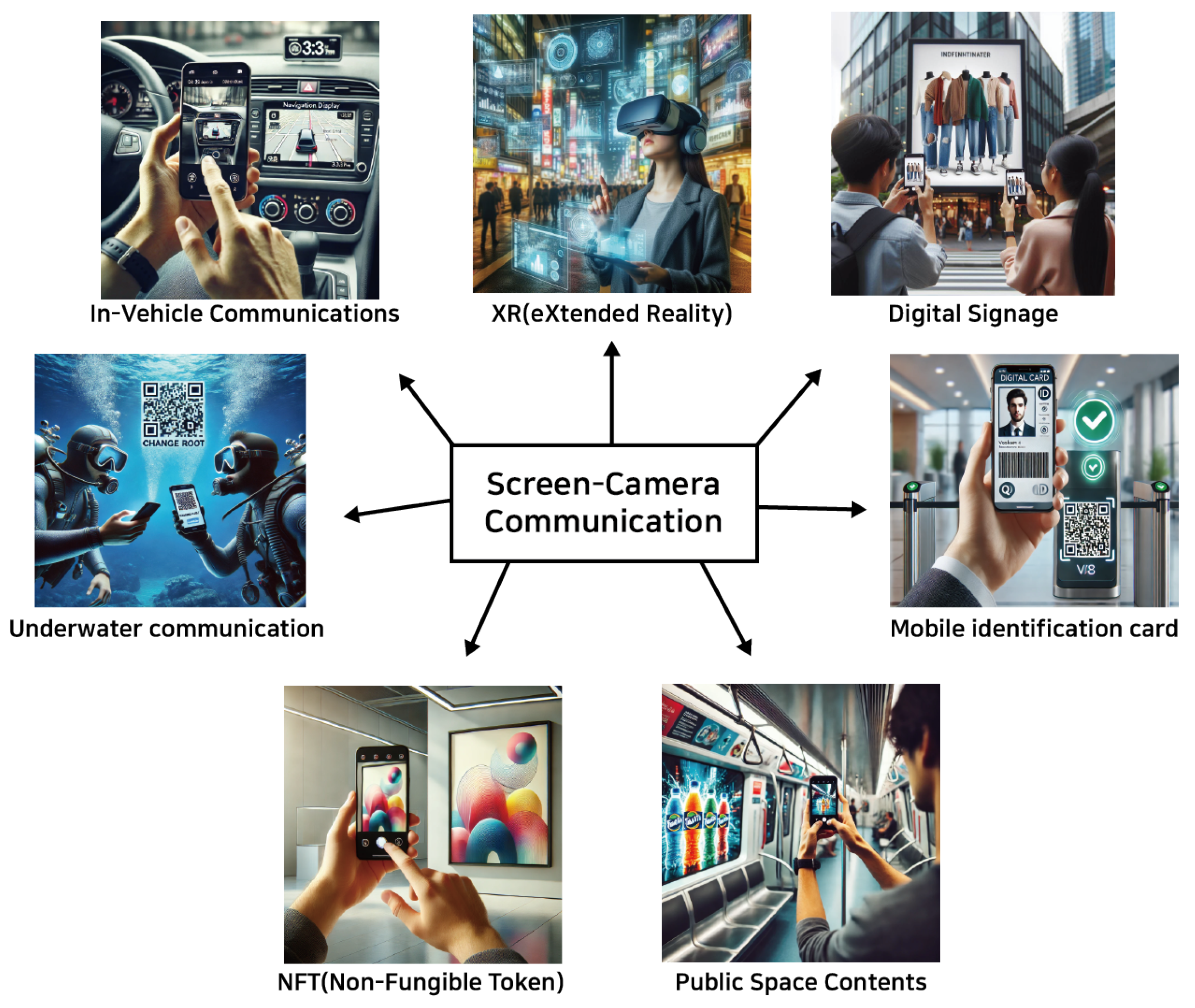
In the context of near-field D2D communication, SCC enables a wide range of applications, including secure peer-to-peer data exchanges, multiplayer gaming, and collaborative work in close proximity. An interesting variant of D2D SCC is its application in in-vehicle communication. For example, displays within a vehicle can transmit navigational information, alerts, or entertainment directly to passengers’ devices. Similarly, information screens at bus stops or train stations can communicate timetables or service updates when users capture them with their devices. Augmented reality (AR) is a natural extension of SCC, and its applications are inherent to the technology. Figure 3 illustrates various SCC applications, including eXtended reality (XR) and digital signage, among others. An exciting potential application of SCC lies in the NFT space, where it could be used to verify ownership or display digital art. Users could scan a screen displaying an NFT with their mobile device to confirm its authenticity or interact with it in various ways. Another interesting application could be in art museums, where additional information about any digital art could be embedded within the artwork itself, which can be accessed by interested persons by scanning the painting.
Apart from typical environments, SCC also has the potential to operate in harsh settings, such as underwater environments, where turbulent effects are prevalent [19,20,21]. In underwater environments, radio waves attenuate rapidly, and acoustic communication suffers from issues like low bandwidth, significant delays, and high susceptibility to noise and multipath effects. In contrast, SCC systems rely on light-based communication, which is less affected by these turbulent effects. Underwater turbulence, caused by water currents, temperature variations, or particulate matter, can scatter acoustic signals, but optical communication using light offers a more stable medium over short distances. While water clarity (turbidity) can impact light-based communication, advanced modulation techniques such as CSK or OFDM can enhance robustness by dynamically adapting to changing environmental conditions. Moreover, SCC can achieve significantly higher speeds and enable real-time data transmission and environmental monitoring, offering lower latency and greater efficiency compared to traditional communication.
Figure 3. SCC applications: images generated using ChatGPT [22] based on SCC applications in 6G and beyond.
Photonics 11 01000 g003

4. Types of SCC

Existing SCCs can be broadly classified into two categories:
  • Visible SCC—Visible SCC refers to communication methods between a screen and a camera where the transmitted information is explicitly visible to the human eye. This typically involves the use of visual patterns such as QR codes, barcodes, or other types of graphical data that a camera can capture and process. Since the information is visible, users can easily see the content being transmitted, often requiring direct interaction, such as scanning a QR code or interpreting a visual cue on the screen.
  • Hidden SCC—Hidden SCC, in contrast, involves transmitting information in a way that is invisible or not perceptible to the human eye. This allows data to be embedded without interfering with the user’s visual experience. A key consideration in designing hidden SCC systems is ensuring that data transmission does not degrade the quality of the visual content displayed. Achieving this balance is crucial, as the primary function of screens is to present visual contents to viewers. Therefore, the modulation techniques used must be subtle enough to remain imperceptible or minimally invasive to the user experience, while still being detectable by a camera.
Figure 4 provides a deeper classification of SCC. Visible SCC primarily involves the use of QR codes and color QR codes. In contrast, hidden SCC is classified based on the embedding region of the image frame, where the data are embedded, whether in the spatial domain, the spectral domain, or through more advanced techniques such as ML. The detailed schemes described in the paper are summarized in Table 1 and Table 3.
Table 1. Classification of Visible Screen-Camera communication.
CategorySub-CategoryProtocolDescription
Visible SCCQR codeShiftCode [23]Encodes data using shifting shape patterns to improve barcode capacity and solve frame mixture issues.
Pre-Processing [24]Enhances reliability by pre-processing images to mitigate distortion caused by angle and distance in screen-to-camera communication.
Screen OFDM [10]Uses 2D-OFDM to improve data rate and reduce error rates in optical camera communication over larger distances and angles.
Secret hiding [25]Embeds secret messages in QR codes using Hamming code, improving security while maintaining QR code’s fault tolerance.
UQCom [26]Underwater communication system utilizing blue-green QR codes and image enhancement to ensure real-time and secure communication.
Color QR codeStyrofoam [27]Addresses interference with blank frames, improving throughput by 2.9x.
RDcode [28]Enhances reliability and doubles transmission rate using multi-level error correction.
RainBar [29]Optimizes color barcode decoding under dynamic conditions.
Dynamic code [30]Boosts real-time rates to 320 kbps with color multiplexing.
CCB-OCC [31]Uses invisible complementary color barcodes for robust short-range communication.
SCsec [32]Ensures secure communication using color shift for key distribution
CALC [33]Reduces errors with real-time ambient light calibration.
RescQR [6]Recovers data from composite frames, achieving high throughput.

4.1. Visible SCC

4.1.1. QR Code

A QR code is a two-dimensional barcode that can store significantly more information than traditional one-dimensional barcodes and can be accurately scanned from various angles. One example, ShiftCode [23], uses shifting shape patterns to enhance barcode capacity and addresses the frame mixture issue caused by the rolling shutter effect in CMOS cameras. Another approach [24] improves SCC reliability by pre-processing images based on the relative positions of the screen and camera, effectively broadening the communication range. An SCC system utilizing 2D-OFDM was proposed [10], achieving more than ten times the data capacity of existing systems. Additionally, an efficient mechanism has been developed to embed secret messages within QR codes using the (8, 4) Hamming code, which leverages QR codes’ error correction capabilities to enhance secret payload capacity and embedding efficiency [25]. Lastly, the UQCom [26] system offers a robust method for underwater communication, using 3D blue-green QR codes enhanced with image processing technology. Extensive experiments have validated its high throughput and real-time communication capabilities.

4.1.2. Color QR Code

Recent advancements in color QR code technology have been introduced to overcome the limitations of traditional QR codes, which encode information using only black and white. Styrofoam [27] presents a coding scheme that reduces inter-symbol interference by incorporating blank frames into transmission patterns. RDCode [28] proposes a dynamic barcode designed to improve reliability and throughput over screen–camera links, employing a novel packet-frame-block structure and tri-level error correction schemes. RainBar [29] introduces a high-throughput visual communication system using color barcodes optimized for screen–camera links, with innovative synchronization and localization techniques that enhance decoding accuracy and data transmission rates. Another SCC system [30] improves data transmission efficiency by encoding a color-multiplexed dynamic QR code into a dynamic video stream. Complementary color barcode optical camera communication (CCB-OCC) [31] provides a robust, camera-detectable method for data transmission that remains invisible to the human eye. SCsec [32] is a secure SCC system leveraging the color shift effect to establish secure communication and prevent eavesdropping between closely positioned devices. CALC [33] introduces a calibration method to mitigate ambient light interference, using calibration frames to enhance transmission accuracy. Lastly, RescQR [6] offers a reliable data recovery system that addresses composite video frame issues caused by high display rates and slow camera capture, utilizing a mixture separation algorithm and Viterbi-based inference for effective data recovery.
Table 2 compares the data rates of various visible SCC schemes. The ADR varies depending on the techniques used and the input media type, which is typically an image. For example, the grayscale mode of Shiftcode [23], which uses two colors (black and white), demonstrated approximately 1.5 times higher ADR compared to that achieved using four colors, outperforming RDcode [28] under similar conditions. Additionally, a dynamic code [30], used at closer ranges with input images over five times larger, achieved increased data transmission, reaching approximately 320 kbps.

4.2. Hidden SCC

Hidden SCC involves embedding data into image frames discreetly, so as not to disrupt the visual viewing experience for the viewer, as shown in Figure 5. This is achieved by embedding data in either the spatial or spectral domain of the image. Additionally, advanced ML algorithms can be utilized to conceal data within the image frames.
Figure 5. The concept of hidden SCC: Simultaneous communication over the full frame of the same visible channel, with display-to-eye for image/video and display-to-camera for data transmission [11,12,34,35].
Photonics 11 01000 g005
Table 3. Classification of hidden screen-camera communication.
CategorySub-CategoryProtocolDescription
Hidden SCCSpatial domainInFrame [11,12]Enable full-frame, dual-mode screen-camera communication, preserving the viewing experience with complementary frame multiplexing
HiLight [36]Hides data in pixel translucency changes for unobtrusive communication
Disco [34]Uses rolling shutter sensors for temporal signal-based communication, robust to occlusions and blur
ChromaCode [8]Achieves high data rates with imperceptible flicker using adaptive lightness modification
UnscreenCode [37]Invisible barcode system using image-based extraction, designed for reliable decoding with off-the-shelf devices
Temporal
sampling [38]
Achieves high-rate, asynchronous display-camera communication with invisible modulation, ensuring data integrity without synchronization markers
Mobiscan [35]Ensures real-time, secure communication with fast frame correction and a flexible capture angle for IoT applications
AirCode [39]Combines invisible visual and inaudible audio channels for reliable, high-rate data transmission with over 1 Mbps throughput
Spectral domainConventional-DFC [9]Embeds data in the spectral domain of video frames, ensuring unobtrusive transmission without visible artifacts
2D-DFC [40,41]Utilize 2D modulation in the spectral domain for display-to-camera communication, enhancing data rates while maintaining minimal visible artifacts
Color-DFC [42]Enhances DFC by evaluating the effectiveness of various advanced receivers (ML, MMSE, ZF), achieving robust performance under noise and distortion
Iterative-DFC [43,44]Transmit data via spectral embedding, using iterative image reconstruction to boost rates without visible artifacts or reference frames
SDE-DFC [45]Proposes multiple frequency-based data-embedding mechanisms, achieving robust data recovery in noisy wireless optical channels
Experimental-DFC [46]Uses DCT and turbo coding to improve data transmission reliability under noise and distortions
Video-DFC [47]Embeds data in video frames, achieving 27 kbps with frame synchronization and enhanced data recovery
Interpolated
Video-DFC [48]
Reduces error rates and boosts data rates by 2.3 kbps using interpolated reference frames
Deep learningTexturecode [49]Uses spatially adaptive embedding for flicker-free communication at 22 kbps
HiDDeN [50]Uses convolutional neural networks (CNNs) to jointly train an encoder and decoder for hiding and recovering data in images
LFM [51]Embeds messages in images using a camera-display transfer function (CDTF) to model the distortions
StegaStamp [52]Embeds invisible hyperlinks in photos, enabling robust retrieval despite distortions
DeepLight [7]Achieves real-time screen-camera communication using blue-channel modulation, up to 1.2 kbps
Deep D2C-Net [53]Leverages hybrid layers to combine feature maps from cover images and data, ensuring robust embedding with minimal visual impact
RIHOOP [54]Embeds invisible hyperlinks into images, using a 3D distortion network to ensure reliable extraction under various conditions
TERA [55]Enables high-transparency screen-to-camera communication using color decomposition, with strong adaptability and robustness
Dense D2C-Net [56]Improves image quality and robustness in D2C communication by utilizing dense connections for feature reuse

4.2.1. Spatial-Domain Embedding

Significant research has been conducted in the spatial domain to hide data within digital images by manipulating pixel values. Unlike visible SCC methods, spatial-domain techniques embed data directly into the image, making the hidden data less noticeable while still maintaining efficiency. InFrame [11] introduced a dual-mode, full-frame communication system that allows simultaneous video viewing and data transmission with minimal visual distortion by using complementary frame designs. Building on this, InFrame++ [12] enhanced the system with spatial-temporal complementary frames, hierarchical data structures, and CDMA-like modulation, significantly improving data rates while preserving visual imperceptibility. HiLight [36] embedded data into pixel translucency changes, imperceptible to the human eye but detectable by camera-equipped devices, enabling seamless data transmission without altering visible screen content. Similarly, DisCo [34] used rolling shutter sensors to transform high-frequency temporal modulations into spatial flicker patterns, enabling robust message transmission that remains undetectable by human viewers. ChromaCode [8] provided a fully imperceptible method for embedding data into video frames using a uniform color space and adaptive lightness adjustments. UnseenCode [37] proposed an invisible on-screen barcode scheme that embeds data into the chromatic components of content using inter-frame embedding. Additionally, a study by [38] proposed a method for accurately recovering display frames from non-synchronized camera recordings using differential modulation, without the need for synchronization markers. MobiScan [35] enhanced IoT communication by integrating a fast frame correction technique with a multilevel data pattern scheme, improving speed and data security. Lastly, AIRCODE [39] introduced a hidden communication system that combines an imperceptible visual channel with an inaudible audio channel, facilitating data transmission between screens and cameras without disrupting the user experience.
Table 4 compares the data rates of various spatial-domain-based hidden SCC schemes. All methods used 1920 × 1080 video as the input media, with data bits embedded across approximately 16 blocks at a high refresh rate of 120 Hz . Among these approaches, Aircode [39] achieved the highest quality and ADR, outperforming Chromacode [8] and Inframe++ [12].

4.2.2. Spectral-Domain Embedding

The concept of DFC [9] was first introduced as a technique to embed data in the spectral domain of image frames, enabling simultaneous data transmission without disrupting the viewer’s experience. This approach was later enhanced with two-dimensional DFC (2D-DFC) [40], significantly increasing the ADR. Subsequent research focused on improving the performance of DFC systems with advanced receivers [42], leading to better data extraction and increased resilience against channel noise. Building on these advancements, iterative spectral image reconstruction techniques [43] were developed to boost data transmission by improving the quality of recovered images without the need for reference frames. Iterative reconstruction techniques incorporated pilot symbols for reference frame generation. These schemes are known as iterative DFC [43,44,57]. Additionally, new spectral domain embedding mechanisms were introduced, enabling robust data transmission even under challenging conditions, while ensuring compatibility with off-the-shelf cameras and displays and maintaining visual imperceptibility [45]. The real-world feasibility of DFC was demonstrated in [46] through practical lab experiments, integrating ML for object detection and employing turbo channel coding for error correction to enhance performance. Following this, video DFC [47] improved data rates by embedding data into each divided video frame rather than fixed image frames. This system standardized the frame packet structure and employed a color-coded 4-point block pattern for frame synchronization and accurate data extraction. To further enhance video DFC, an interpolation-based reference image estimation technique was introduced in [48], which improved data detection accuracy by generating reliable reference frames, reducing error rates by approximately 69% compared to traditional methods. Finally, [41] highlighted that in 2D-DFC, the diagonal data embedding method outperforms the orthogonal approach in reducing bit error rates (BER). As DFC is a key focus of this survey, we will provide a detailed comparison of various DFC schemes toward the end of the manuscript.

4.2.3. Deep Learning Methods

Recent advancements in deep learning techniques have demonstrated exceptional capabilities in recognizing and learning complex data patterns. These methods autonomously develop optimal data-hiding strategies through training, offering the flexibility to adapt to varying data sizes and types. Deep learning techniques hold a significant advantage over traditional methods by enabling data hiding in more complex and non-linear ways, making it harder for pattern-based detection algorithms to identify hidden information. For example, a high-rate, flicker-free SCC method using spatially adaptive embedding optimizes data encoding by exploiting visual features such as edges and textures [49]. HiDDeN [50] combines an encoder, noise layer, decoder, and adversarial network to ensure visually imperceptible data embedding, allowing reliable data extraction even after transformations such as compression and cropping. Light field messaging [51] introduces a camera–display transfer function (CDTF) to model and mitigate distortions during the display and capture process, ensuring reliable message retrieval with minimal visible artifacts. Another ML-based SCC method, StegaStamp [52], embeds hyperlinks in physical photographs in an imperceptible way to the human eye. StegaStamp uses a deep neural network (DNN) to learn an encoding/decoding algorithm that is robust against distortions that occur during printing and photography. The system was evaluated on a dataset of real-world photos, where it successfully recovered hyperlinks with high accuracy, even when the photos were subject to various distortions and multiple rounds of printing and re-photography. Additionally, DeepLight [7] employs a DNN to decode imperceptible data encoded on screens by modulating the blue color channel. It achieves high data rates with minimal flicker.
Deep D2C-Net [53] improves data embedding and reduces visible artifacts through a novel encoder structure that combines feature maps from both the cover image and embedded data. RIHOOP [54] introduces a just noticeable difference (JND)-based loss function that leverages HVS properties to enhance visual quality. It also uses a 3D rendering-based distortion network to simulate camera-induced distortions, improving the robustness of hyperlink extraction in real-world scenarios. The TERA system [55] advances these techniques by combining color decomposition-based encoding with a superposition-based scheme, supported by an attention-guided information decoding network. This combination achieves high transparency, efficiency, robustness, and adaptability in screen-to-camera image communication. Finally, dense D2C-Net [56] leverages a dense connection network to robustly embed and decode data within the Y channel of display images. By using hybrid layers and noise-resistant training, it maintains high visual quality and ensures low BER, making it a strong candidate for reliable and imperceptible data communication in practical applications. Deeplight [7] incorporates ML models into the decoding pipeline to achieve humanly imperceptible, moderately high data rates under diverse real-world conditions. Deeplight’s key innovation lies in the design of a DNN-based decoder that collectively decodes all the bits spatially encoded within a display frame, without precisely isolating the pixels associated with each encoded bit. Additionally, Deeplight supports imperceptible encoding by selectively modulating the intensity of only the blue channel, while providing reasonably accurate screen extraction using state-of-the-art object detection techniques.
Table 5 compares four deep learning-based techniques within hidden SCC. All four techniques used images as the input media, with each image embedding 200 bits of data. Three of the techniques, excluding HiDDeN [50], achieved a maximum data rate of 12 kbps with no BER, while both dense D2C-Net [56] and deep D2C-Net [53] recorded a PSNR of approximately 30 dB.
Next, we will focus on the main topic of this manuscript, that is, DFC, and review the significant achievements in this area.

5. DFC System

5.1. System Architecture

As shown in Figure 4, SCC is a broad concept that encompasses the transmission and reception of information through visual displays. It includes various methods, such as QR code (visible SCC) and hidden SCC. In contrast, DFC is a specific subset of SCC that leverages the spectral domain of image frames to enable unobtrusive information exchange. This approach modulates the frequency coefficients of the image in a way that allows that data to be captured and decoded by a camera. The region where data are embedded is referred to as the sub-band, and the resulting data-embedded image frame is capable of transmitting information to a camera or device. In the following sections, we will explore how DFC integrates more complex signal processing algorithms across different sections of the image frames and videos.
The DFC system architecture consists of two main components: the display and the camera. Figure 6 shows the basic block diagram of DFC [9]. The process begins with the host image, the original image frame into which data will be embedded. Before embedding, the image undergoes frequency conversion, transforming it into the frequency domain. Simultaneously, the input data are optionally channel-coded for error resilience and then modulated. The encoder embeds the modulated data into the image using various techniques [45], which will be discussed later. After encoding, the data-embedded image is converted back into the spatial domain through inverse frequency conversion and displayed on the screen. A reference image, which is not data-embedded, is transmitted alongside each data-embedded frame (cf. Figure 7). The reference image serves two purposes: it assists in decoding the embedded data at the receiver and allows the display to perform its original visual function without noticeable disruption. Since the refresh rate of the display is typically 60 Hz or higher, the human eye cannot distinguish between the reference and data-embedded frames.
At the receiver, the displayed data-embedded and reference images are captured by a device, such as a camera. These captured images may contain distortions from the display process or channel noise, so they first undergo distortion correction. Once corrected, the images are converted into the frequency domain for data extraction. The decoder uses the reference image to retrieve embedded data, reversing any channel coding applied during the embedding process. Finally, the extracted data are demodulated to recover the estimated information bits. Next, we will discuss the key signal-processing aspects of DFC.

5.2. Display-to-Camera (D2C) Channel Models

In a DFC system, the channel between the display (transmitter) and the camera (receiver) can be modeled similarly to VLC channels, which are typically line-of-sight (LOS) and influenced by environmental factors such as ambient light interference. In all DFC scenarios, we assume that both the transmitter and receiver are stationary, meaning that the channel characteristics remain stable over time. This assumption is reasonable for scenarios where channel variations occur slowly. In addition, we assume perfect alignment between the screen and the camera. In this case, all light-emitting pixels from the screen are focused by the camera’s pixels, resulting in no loss of signal energy. Frame synchronization is also assumed to be perfect. However, in practical settings, background noise may distort the intensity values captured in the frame. In this scenario, the simplest channel model is the additive white Gaussian noise (AWGN) channel [9,40]. The received images over the D2C link in an AWGN channel can be mathematically expressed as [9,40]
Y t = I t + N t ,
where Y t is the received data-embedded image, I t is the transmitted image frame, N t represents the AWGN matrix, and the subscript t denotes the time-domain processing. Note that this fundamental channel model also accounts for issues such as low contrast and non-uniform illumination. In addition, a camera shake when holding the camera during image capture can introduce phase noise in the embedded data. From a mathematical perspective, any phase noise will distort phase-modulated data and can be modeled as AWGN. Note that the noise is assumed to be uniform across the image sensor and is quantified by its variance.
However, when misalignment occurs, the light rays from the screen pixels do not focus properly onto the camera pixels, leading to a reduction in signal energy. This loss of signal energy also increases the noise present in the camera pixels. In such scenarios, additional factors, such as path loss and blooming, must be accounted for [42]. In the D2C channel, attenuation between different pixels’ brightness on the screen occurs as light passes through the camera lens to the image plane. Ideally, for a given camera aperture, the attenuation would be uniform across the entire image. However, due to geometric optics constraints, brightness decreases as the distance from the center increases. This phenomenon can be modeled using the “cosine fourth” law, expressed as [58] follows:
E Θ E 0 = cos 4 Θ ,
where E Θ is the signal energy on an off-axis pixel, E 0 is the energy on an on-axis pixel, and Θ represents the angle at which the screen pixels are off-axis. Consequently, the received pixel intensity can be described as [42]:
Y t = I t cos 4 θ t ,
where θ t is the off-axis angle for a given pixel. Another important distortion in the D2C channel is blooming, which occurs due to charge leakage between adjacent pixels in a charge-coupled device (CCD) sensor. Each CCD pixel has a limited charge capacity, and when this limit is exceeded, the excess charge leaks into neighboring pixels. This leakage causes a bright light source to appear hazy, extending beyond its original borders. While this effect is usually imperceptible, extremely bright light sources can make it more noticeable. Blooming can be approximated as a blurring effect followed by an enhancement of the blurred image, which results in a reduction of contrast [59]. The spatial response of an imaging system is characterized by its point-spread function (PSF) [60], where the blurring effect, caused by imperfect focus, follows a two-dimensional Gaussian distribution [61]. The blurred pixels can be modeled as the convolution of the received pixels with the PSF, as follows [42]:
Y ˜ t = Y t h t ,
where ⊗ denotes 2D linear convolution and h t is the PSF for the corresponding frame.
Another important distortion to consider in the DFC channel is geometric distortion [9,40]. Due to the nature of camera imaging mechanisms, the electronic screen may not always be perfectly aligned with the camera, leading to geometric distortions. These distortions occur when the screen is captured from an angle or perspective that results in the deformation of the pixel areas in terms of both shape and size. To account for these effects, perspective distortions are modeled as a composite result of scaling, rotating, and twisting the pixel areas caused by the camera’s projection mechanism (cf. Figure 8). The projection matrix that describes these distortions can be expressed as follows [9]:
P = ϵ cos ϕ ϵ sin ϕ t ϵ sin ϕ ϵ cos ϕ t 0 0 1 ,
where ϵ represents the scaling factor, ϕ is the rotation angle, and t is the twisting factor. It is important to note that the camera must capture the entire image area because the embedded data are spread across the entire spatial domain of the image. Therefore, a large standoff distance, which allows the camera to capture the full image area, is required. The above-mentioned distortions are the most common ones used in designing the D2C channels for DFC simulations and experiments. However, in a practical outdoor DFC scenario, additional channel distortion effects can occur, such as the display being larger than the sensor’s field of view (FoV), parts of the display being occluded, or defocus blur. These effects are not considered in the current study, as they require more advanced coding and extraction mechanisms, which are part of the future research.

5.3. Modulation Techniques

Various modulation techniques are used in DFC to encode information into the pixels of the display, enabling data transmission to the camera. In the pioneering work on DFC [9], 2-QAM (BPSK), 4-QAM, and 16-QAM were employed. BPSK is one of the simplest and most robust digital modulation schemes, but it offers lower data transmission efficiency. In contrast, 16-QAM provides higher data rates. A detailed list of these modulation techniques is presented in respective tables.

5.4. Intensity Levels

Intensity levels refer to variations in brightness that are used to encode and transmit data. In our DFC system, intensity levels are not directly modulated, as the data are embedded in the frequency domain. However, the effect of intensity variations is observed at the receiver. For example, in [9], it was shown that when the camera views the screen at an angle, the perceived intensity levels may degrade, leading to errors during decoding. Additionally, in outdoor scenarios, strong external light sources, such as sunlight, or shadows can interfere with the receiver’s ability to accurately detect the transmitted intensity levels. In these cases, intensity-based modulation schemes [62,63] can be employed to mitigate these effects.

5.5. Received Signals

A typical camera system consists of an imaging lens, an image sensor, and additional image processing components. When the image frame is grayscale, it is directly converted to the frequency domain to decode the data. However, in the case of color DFC [42], where the image frames are color, a repeating filter pattern, typically R, G, and B, is applied over the image sensor to capture the color information. A widely used filter is the Bayer color filter array [64], which follows a repeating 2 × 2 pattern for digital color image acquisition. This pattern allows the RGB signal to be separated into individual color channels. The captured image can therefore be split into its respective color channels as follows [42]:
Y ¨ t , j = Y ˜ t , j + N t , j ,
where j { R , G , B } represents the R, G, and B channels, respectively. Each of the channels is then decoded individually.
In addition to conventional techniques, deep learning techniques can be applied to enhance BER performance [46]. One key challenge in capturing display images is ensuring proper alignment between the display pixels and the camera’s focus. If not properly aligned, the camera may capture unwanted background elements, depending on the distance. To address this issue, a deep-learning-based object detection method can be used, replacing traditional image processing techniques to isolate the display area more effectively. Specifically, we employ YOLOv4 [65], which improves detection accuracy by over 10% compared to YOLOv3 [66], owing to enhancements such as bag-of-freebies and mosaic augmentation. Once the display area has been corrected for distortion, we can extract the embedded image by identifying the four corner points using OpenCV correction algorithms [46].

6. Communication and Signal Processing in DFC

6.1. Frequency Conversion

Frequency conversion involves transforming an image from its original spatial domain into the frequency domain. This transformation allows data to be embedded into specific frequency components of the image frame, which can either be more resilient to noise and distortions or less perceptible to human viewers. By leveraging the frequency characteristics of the image, this technique enables efficient data embedding and transmission. A key signal processing technique used in DFC for frequency conversion is the Fourier transform [9,40]. By applying the discrete Fourier transform (DFT) to an electronic display image, the image is converted from the spatial domain to the frequency domain. In the frequency domain, the image is represented by its frequency components, with each component corresponding to a different frequency within the image. For example, low-frequency components represent smooth variations, while high-frequency components capture edges and fine details. DFC uses specific sub-bands to embed data, as shown in Figure 9. The white region in the figure indicates a sub-band. Another transform used in DFC is the discrete cosine transform (DCT) [45,46]. While both transforms share similarities, they have distinct characteristics. The DFT represents an image as a sum of complex sinusoidal functions with varying frequencies and phases, providing a complete representation of the image’s frequency components, including both real and imaginary parts. In contrast, the DCT is a variant of the DFT that produces only real-valued coefficients. It transforms an image into a sum of cosine functions with different frequencies.
Regardless of the image transformation method used, the frequency-domain image contains low-, mid-, and high-frequency components. The most important visual characteristics of the image are located in the low-frequency range, while details and noise are found at higher frequencies. Since the HVS is more sensitive to lower frequencies, embedding data at very low frequencies can degrade image quality and distract the observer. Conversely, embedding data at high frequencies minimally impacts the image, as the artifacts introduced are subtle and less noticeable. This is demonstrated in Figure 9, which shows data-embedded images in both low- and high-frequency sub-bands. Therefore, in this study, we choose to embed data in high-frequency sub-bands to avoid distracting from the display’s original function of showing content. Moreover, as we will discuss later, embedding data in high-frequency sub-bands can lead to better performance even without transmitting reference frames.

6.2. Modulation and Data Embedding

Fundamentally, DFC can be classified into two categories: reference frame-based DFC and pilot-based DFC. As the name suggests, reference frame-based DFC uses reference frames to decode data at the receiver, while pilot-based DFC, also known as iterative DFC, does not use reference frames and instead estimates them using pilot signals at the receiver. Regarding data embedding, DFT employs multiplicative data embedding, similar to embedding signals in the subcarriers of an OFDM-based communication system. This technique involves applying multiplicative coefficients to the pixel values of an image [9,40]. In contrast, DCT supports additive, multiplicative, and exponential data embedding [45]. Additive data embedding [46] involves simply adding the data to the original image, while exponential embedding uses a logarithmic transformation of the coefficient vectors. The work in [45] provides an overview of spectral domain data embedding (SDE) techniques in DFC using the DCT image transformation method.

6.2.1. Reference Image-Based DFC

As shown in Table 6 and Table 7, reference frame-based DFC includes conventional [9], 2D [40,41], color [42], experimental [46], and video DFCs [47]. The key differences between these variants lie in the signal processing methods used for data embedding. Conventional DFC uses DFT with multiplicative data embedding. Color DFC applies DFT to color images rather than grayscale images. 2D DFC embeds data in both dimensions of an image frame. Experimental DFC involves practical lab experiments under various constraints and employs ML techniques to extract the display region at the camera receiver. It also uses DCT and additive data embedding with color images. Video DFC extends experimental DFC by using videos instead of static images. This allows for the transmission of large amounts of data, as different data can be embedded in each frame of the video. In terms of modulation, as mentioned above, BPSK and QAM are most commonly used for data encoding and transmission in DFC. Note that both BPSK and QAM can be used with DFT, whereas only BPSK can be used with DCT.

6.2.2. Pilot-Based DFC

While reference frames are useful for data decoding and preserving the original quality of displayed images, their use significantly reduces the system’s data rate. This is because reference frames do not carry data, leading to a decreased data rate. This issue can be addressed using the concept of iterative pilots [43]. This approach employs pilot pixels for reference frame estimation at the receiver, eliminating the need for reference frames [43,44]. Specifically, pilot pixels are embedded within the frame alongside data pixels. After estimating the reference image and decoding data using pilots, the decoded data at the pixels are used as pseudo-pilots. Therefore, iterative decoding with pseudo-pilots significantly improves the data rate of DFC, as no reference frames need to be transmitted. A similar scheme was proposed for 2D DFC [57].
In Figure 9, we observe the data-embedded images generated using four variants of DFC. When data are embedded in high-frequency sub-bands, no noticeable artifacts are visible to the naked eye. Consequently, even when the frame rate is much lower than 60 Hz, the visible artifacts remain imperceptible.

6.3. Channel Coding

Error control is critical for ensuring reliable and accurate data transmission, especially in practical DFC systems. A commonly used technique for error control in DFC is forward error correction (FEC), which involves adding redundant information to the transmitted data. This redundancy enables the receiver to detect and correct errors without requiring retransmissions. The work in [12] employs Reed-Solomon codes, FEC codes, and parity checks, while convolutional coding is used in [45] to mitigate the effects of channel noise, interference, and other transmission impairments. In our study, we use turbo codes for error correction in experimental DFC [46]. Turbo coding is particularly effective because it combines the advantages of both convolutional coding and interleaving through an iterative process. However, the use of channel coding comes at a cost: it reduces overall throughput. Thus, there is a trade-off between reliability and throughput. Repetitive encoding is also employed in 2D DFC [41].

6.4. Demodulation and Data Decoding

6.4.1. Reference Frame-Based DFC

The variants of DFC that use reference frames can be demodulated using a zero-forcing (ZF) receiver, which simply inverts the channel response [9]. Additionally, more advanced receivers like the minimum mean squared error (MMSE) and maximum likelihood estimation (MLE) receivers enhance the decoding performance [42,44]. ZF is straightforward to implement and works well when channel noise is minimal. The MMSE receiver improves on the ZF receiver by minimizing the mean square error between the transmitted and received symbols, accounting for both the channel response and noise. Finally, the MLE receiver is an optimal approach that seeks the most likely transmitted symbols based on the received symbols and the statistical model of the noise and channel [42]. When using the additive technique for data embedding, the subtraction data retrieval method is applied for decoding [41,46,47,48]. This method minimally affects pixel intensity, as the data are directly added to the frequency coefficients. As a result, it reduces visual degradation while enabling efficient data embedding, maintaining image quality, and achieving high data transmission rates and low error rates.

6.4.2. Pilot-Based DFC

In iterative DFC, since there is no reference image, the first step is to estimate the reference image at the receiver. This is done by estimating the spectral image of the display using a set of known pilot symbols. The hard symbol decisions obtained through iterative decoding are then used to enhance the quality of the reconstructed image. In addition to the original pilots, iterative DFC employs iterative pixel estimation using pseudo-pilot pixels, which are selected from the decoded data pixels. This process repeats until the desired accuracy is achieved. Iterative DFC is relatively simple to implement and offers a higher data rate. For demodulation, we used ZF [43,57] and MMSE [44] receivers.

7. Performance Evaluation

In this section, we present a performance comparison of multiple DFC variants. The results are divided based on the input type: first, when the input is a still image frame on the display, and second, when the input is a continuous video. Additionally, the ADR is used as the performance metric, defined as follows [41]:
ADR = ( 1 BER ) D max ,
with
D max = κ L ch ( N 1 ) N f refresh bps ,
where D max is the theoretical maximum data rate, f refresh is the display’s refresh rate, L ch is the number of data bits per channel, N is the total number of frames per packet, and κ is the receiver parameter [41]. From these equations, we observe that the refresh rate directly impacts the number of frames transmitted per second. As f refresh increases, the number of frames transmitted within a given time also increases, leading to an improved data rate. This highlights the inverse relationship between f refresh and D max , where higher refresh rates contribute to higher data rates.

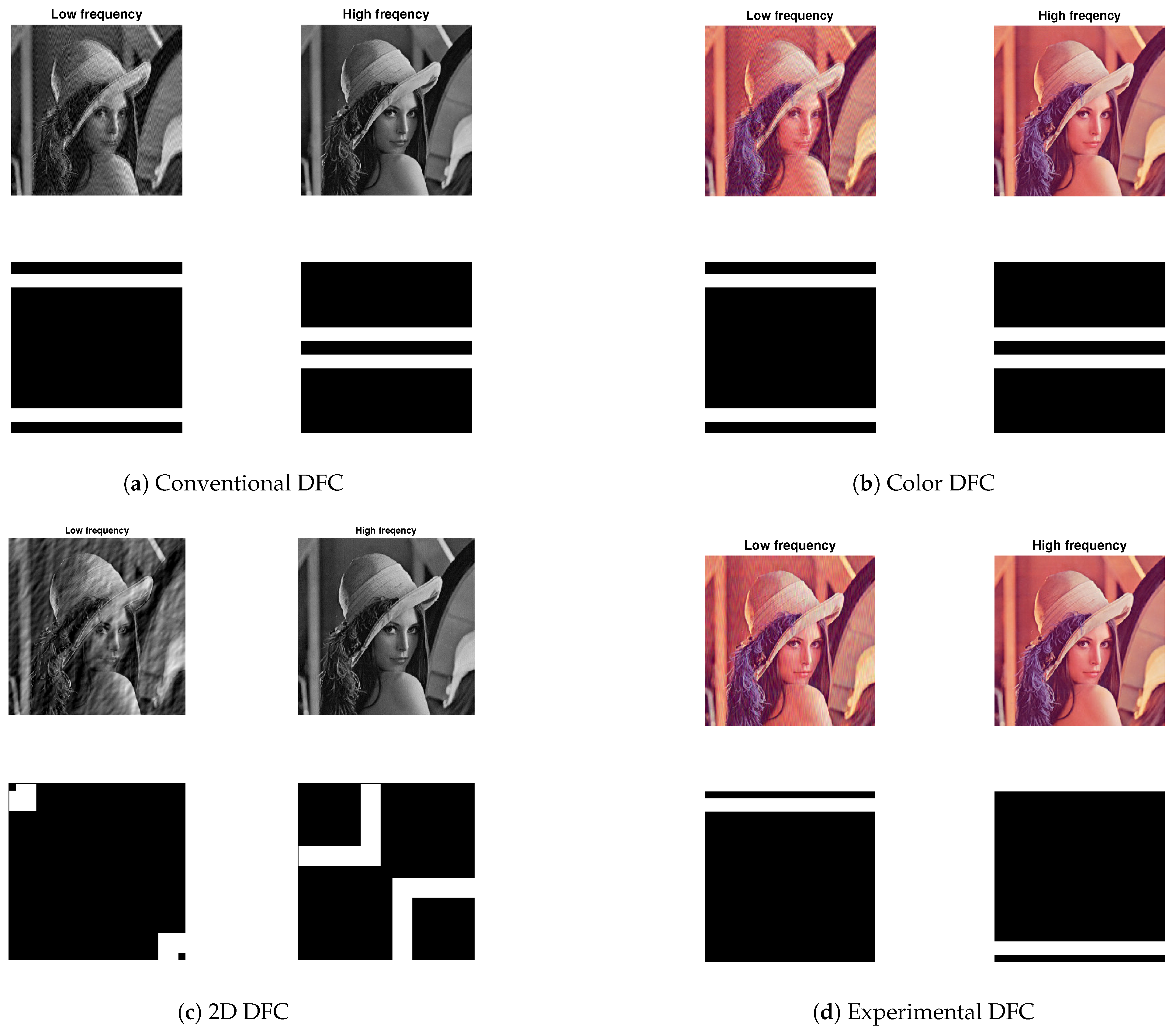
7.1. When Input Is a Still Image Frame

When capturing the display screen, the camera also captures the background, introducing noise into the image. Additionally, this study assumes perfect alignment between the screen and the camera. With perfect alignment, all the light from the screen is focused onto the camera, ensuring no data signal energy is lost. For the simulations, we used grayscale and color Lena image frames of 256 × 256 pixels, with BPSK modulation (cf. Figure 9). The number of embedded data symbols was set to 20 horizontal pixels. For 2D DFC, we embedded up to 30 vertical and horizontal data pixels. A standard 30 fps off-the-shelf camera was used to capture the image frames.
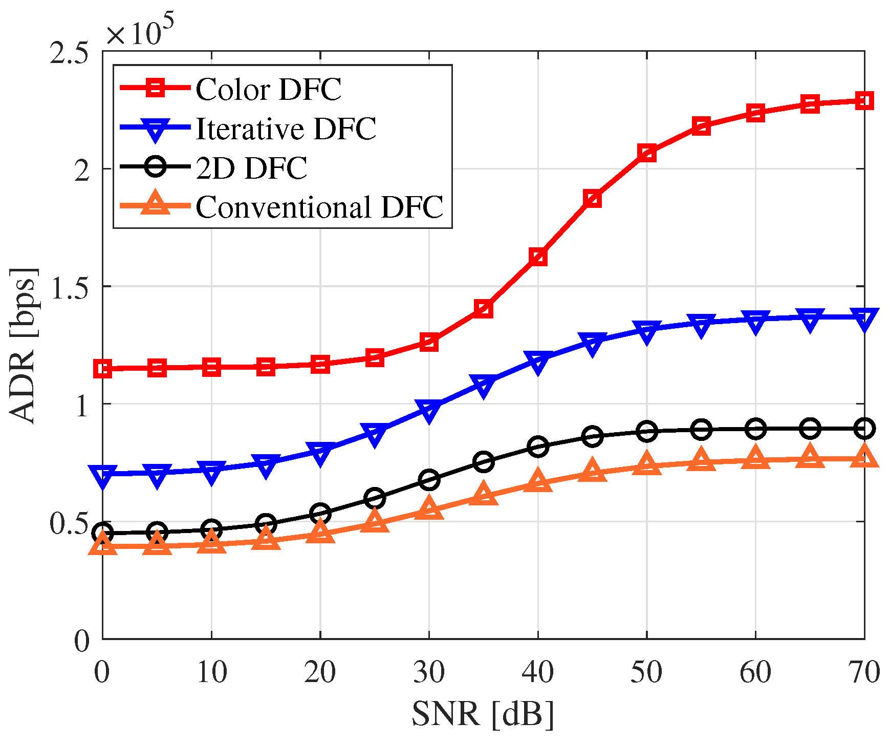
Figure 10 compares four DFC variants in terms of ADR. The results show that conventional DFC performs the worst, while color DFC delivers the best performance. This is because conventional DFC transmits one reference frame per data-embedded frame, resulting in the lowest data rate. In contrast, 2D DFC performs slightly better, indicating that more data can be transmitted using the 2D DFC approach. Iterative DFC achieves even higher data rates as it eliminates the need for reference frames. For implementing iterative DFC, we used 10 % of the total data-embedded pixels as pilots [44], which were uniformly distributed within the sub-bands. Lastly, the results highlight that color DFC delivers the best overall performance. This is because all R, G, and B channels carry data, unlike the other variants, where only a single grayscale channel is used.

7.2. When Input Is a Continuous Video

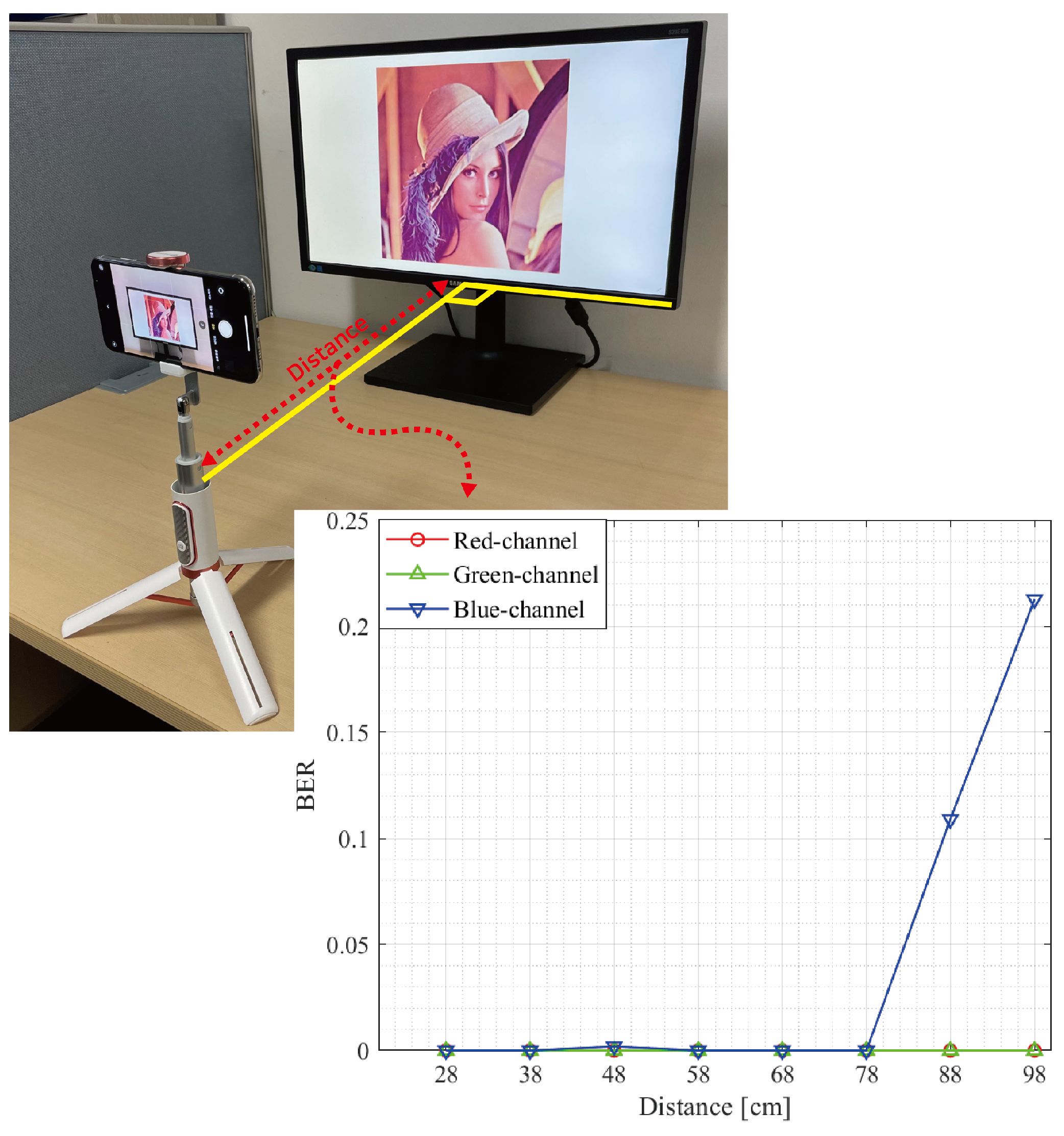
In this section, we consider the scenario where a continuous data-embedded video is displayed on the screen. The experiments were conducted in real-world environments. In such experiments, misalignment between the screen and camera may occur, leading to data signal loss or noise during the capture process. To account for these realistic conditions, we used a 324 × 576 p color video [67] with BPSK modulation and turbo coding. The encoded data size was set to 200 bits per frame. The data-embedded video was displayed on a 60 Hz Samsung monitor and captured using a 120 fps iPhone 15 Pro camera.
The experimental setup is presented in Figure 11. We also present the BER result for experimental DFC conducted in a controlled laboratory environment in Figure 11. The results indicate error-free DFC communication up to a distance of approximately 1 m for both the R and G channels. This demonstrates the feasibility of DFC in real-life applications, suggesting it could potentially replace QR codes. Note that since the BER is zero at most distances, the exact values are provided in Table 8.
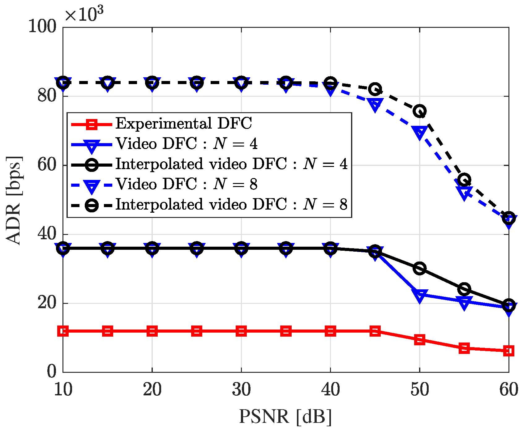
Figure 12 compares the data rate of five real-world DFC variants across different PSNR levels. Up to around 40 dB, all variants maintained a consistent data rate without errors. Video DFC achieved a higher data rate than experimental DFC, as it embeds data in every frame. For both video [47] and interpolated video DFC [48], N represents the total number of frames per packet. Notably, when N is 8, the data rate is higher than that when N is 4. Interpolated video DFC demonstrated higher data rates compared to video DFC. This improvement occurs because, rather than transmitting a single reference image frame, interpolated video DFC generates a new estimated reference frame at the receiver through interpolation for each data-embedded image, allowing all frames to carry data.

7.3. ADR Comparison

Table 9 presents the experimental parameters and a comparison of data rates for various DFC schemes. Both video DFC [47] and interpolated video DFC [48] used video as the input media, except for experimental DFC [46]. By setting the number of frames per packet, N, to 8, video DFC and interpolated video DFC transmitted approximately 7 times more data than the experimental DFC. Interpolated video DFC achieved the highest performance, reaching 76 kbps, particularly when the input had a PSNR of 50 dB.

8. Recent Trends, Challenges, and Future Directions

Though DFC is still in its early stages, the technology has the potential to revolutionize how we interact with devices and the environment. As research and development progress, several challenges remain to be addressed. While we focus on DFC here, many of these challenges also apply to SCC in general, and DFC in particular.

8.1. Machine Learning in DFC

The ML algorithms enable intelligent processing of visual data captured by cameras, improving data rates, error correction, and robustness to variations in channel conditions. Deep learning techniques, particularly convolutional neural networks (CNNs), have significantly enhanced the accuracy and efficiency of tasks such as object detection, image segmentation, and pose estimation.
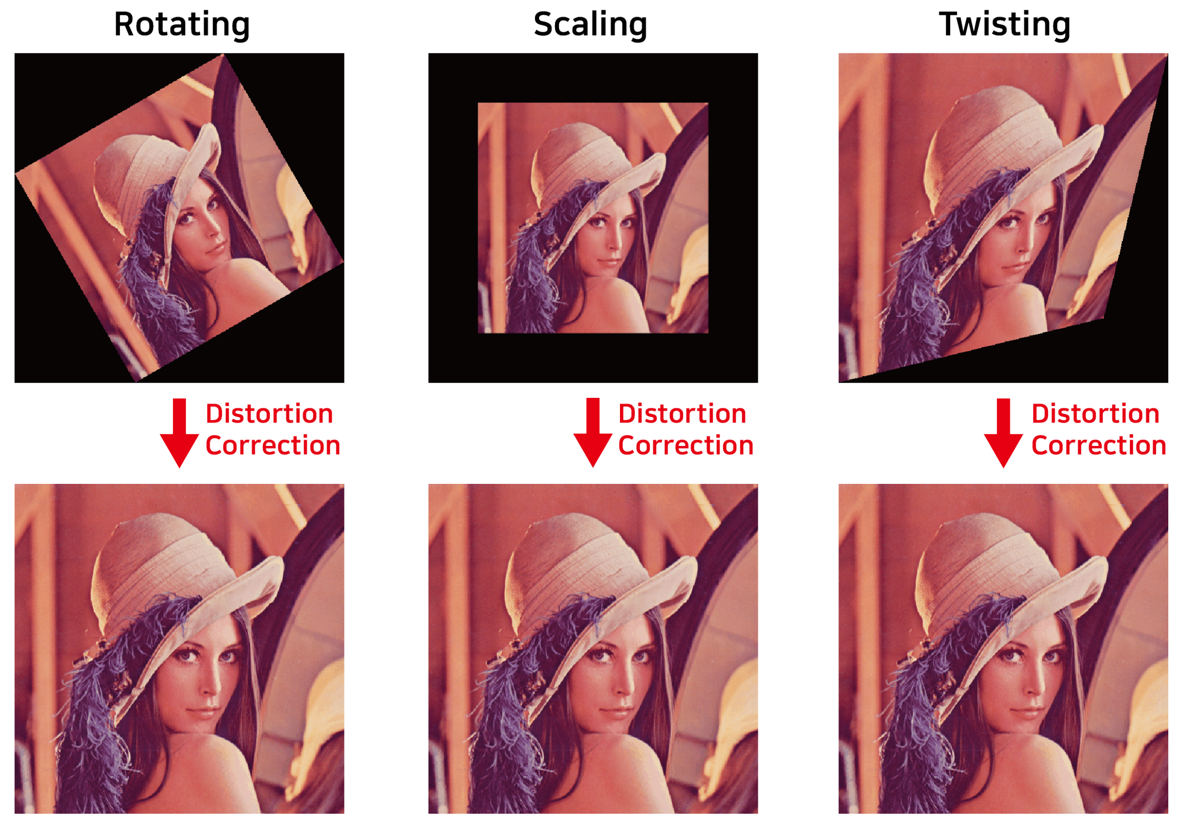
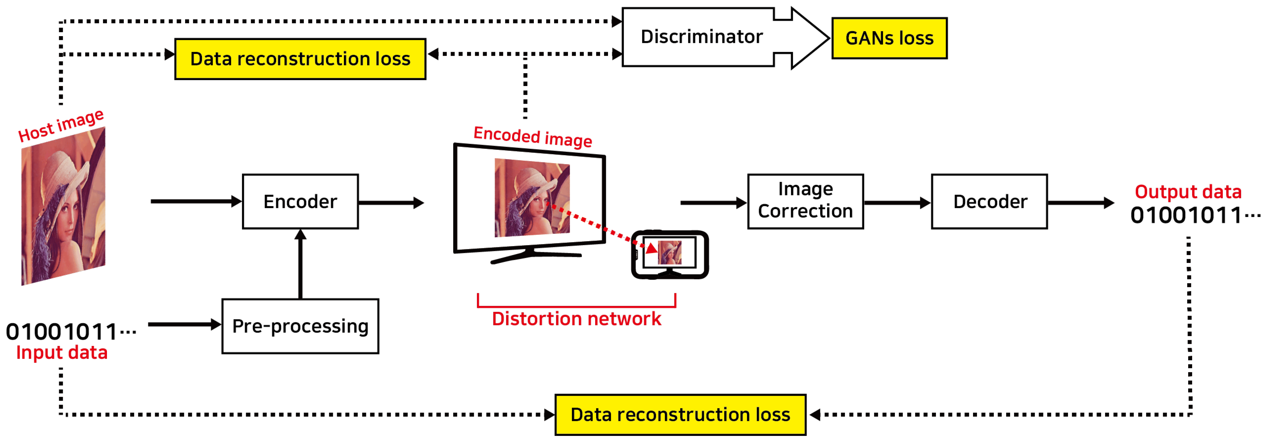
Figure 13 shows a typical ML-based DFC architecture. The structure is divided into two primary components: the encoder network, which embeds data, and the decoder network, which extracts the embedded data. The input image, along with pre-processed data, is fed into the encoder network, where it passes through multiple CNN layers, producing an encoded image containing the embedded data. The encoder seamlessly embeds the secret data into the image. To account for potential distortions in the SCC channel, a distortion network simulates noise and distortions found in real-world conditions, ensuring the system remains robust under challenging D2C environments. Afterward, the image undergoes a correction process to adjust for regional distortions before being input into the decoder network, where the hidden data are extracted. The entire process is managed through end-to-end learning, where the loss generated during training is minimized using back propagation. The network parameters are continuously adjusted to reduce the loss, and through iterative learning, the model’s performance improves. This approach offers strong data security and concealment, making it applicable to a wide range of use cases.
Let us look at the detailed ML-based DFC architectures recently proposed by our lab. In Deep D2C-Net [53], we introduced a DCNN for embedding and extracting data from image frames. It leverages a CNN to learn the relationship between the displayed image and the camera-captured image, improving the data decoding performance. It features fully end-to-end encoding and decoding networks, which generate high-quality data-embedded images and enable robust data recovery, even in challenging screen–camera channels. The encoding process includes hybrid layers, where the feature maps of both the data and the cover images are combined in a feed-forward manner. For decoding, a simple CNN is employed.
Figure 14 illustrates the deep D2C-Net architecture [53], including the encoding and decoding networks. In Figure 14a, the encoder takes upsampled binary data and a cover image to generate a data-embedded image for display. Both the cover image and the data pass through 2D convolutional layers to extract intermediate features, which are then merged into the hybrid layers. These layers concatenate feature maps from both inputs, embedding data into the image. After six hybrid layers, the output is processed by additional convolutional layers to produce the final image. Skip connections between the original image and later layers help preserve key features and prevent degradation, enhancing both PSNR and BER performance by minimizing training losses. On the receiver side, the camera captures the data-embedded image, which may be distorted due to the optical wireless transmission. To correct this, a perspective transformation is applied to adjust the image and extract a corrected version. This corrected image is then fed into the decoder for data extraction. The decoder uses a DCNN to recover the embedded data, learning the complex relationship between the received and transmitted data through deep learning techniques. Unlike conventional receivers that rely on predefined modulation and coding schemes, the deep D2C-Net decoder adapts to varying channel conditions, enabling robust data recovery. It includes multiple convolutional layers for feature extraction, followed by a fully connected (FC) layer that uses binary classifiers to reconstruct the data bit stream, with each classifier recovering a single bit. An upgraded version of deep D2C-Net called dense D2C-Net [56], supports real-time data encoding and decoding. In our other work on experimental DFC [46], the YOLO ML algorithm was employed to detect the display region in the captured image.
However, many applications require real-time data transmission and processing, which demands highly efficient algorithms. This presents a challenge due to the computational complexity of deep learning models. Developing end-to-end systems where both encoding at the transmitter and decoding at the receiver are governed by ML models allows for a fully optimized SCC communication pipeline.

8.2. DFC Channel Model

In both SCC and DFC, channel modeling is crucial. Accurate channel models are essential for designing robust SCC systems that can handle the various distortions and noise inherent in this form of communication. However, developing a comprehensive D2C channel model remains a challenge. In addition to conventional channel characteristics including path loss, blooming, background noise, and geometric distortions, the wireless D2C channel introduces several other non-linear distortions, including defocus blur, occlusion, incomplete screen capture, and display size mismatch with the camera’s FoV, among others. In controlled laboratory experiments, many of these distortions can be neglected since they can be corrected in real time. However, in real-life SCC, these issues must be properly modeled. In contrast, ML techniques, particularly deep learning models, are increasingly being used to estimate and model channel characteristics in SCC [68,69]. These models can learn complex channel behaviors from data, including non-linear distortions, and adapt dynamically to changing conditions. Furthermore, much of the existing DFC work assumes perfect synchronization between the screen and camera. However, in real-life scenarios, synchronization errors may occur during the camera capture process. For example, when the input is a video, the camera capture rate must be at least twice the screen refresh rate to satisfy the Nyquist criteria [47]. Additionally, challenges arise from the rolling shutter effect [47]. Further research is needed to develop a comprehensive SCC channel model that accounts for all these effects. Further investigations may also explore the impact of display and camera type, size, and resolution on SCC.

8.3. Boosting the Data Rate

Although we have eliminated the use of reference frames and nearly doubled the data rate using iterative DFC, it remains limited. While data rates can be directly improved by using larger, high-resolution displays, smarter screens, and higher-quality cameras, more research is needed on the technical aspects. For example, determining how data can be embedded across a large area of an image without introducing visible artifacts on the screen. Another simple way to improve data rates is by using advanced receivers, as DFC infrastructure is not power-limited [42]. Nevertheless, addressing challenges of the D2C channel is crucial for boosting the data rate of SCC systems. For instance, the camera must capture the light emitted from the display with high accuracy to decode the data. This can be difficult in environments with bright ambient light or when the display is not adequately illuminated. Additionally, external light sources such as sunlight or artificial lighting can interfere with the light emitted by the display, making data decoding challenging.

8.4. Real-World Deployment

Designing any communication method involves a trade-off between data rate and robustness. While several methods can achieve high data rates, they often perform only in controlled laboratory settings. In contrast, communication methods applied in consumer settings must operate reliably in uncontrolled, real-world environments, often at the expense of data rate. DFC must work effectively in challenging scenarios, such as when the display is significantly smaller or larger than the camera’s FoV, or in situations involving occlusion, camera rotation, or defocus blur. The system must also perform despite slight screen obstructions caused by external interference. Therefore, future research on DFC (or SCC) should focus on addressing the practical challenges of real-world deployments. Developing robust designs and testbeds will help facilitate the wider adoption of SCC technologies.
Additionally, research could explore integration of SCC with augmented/virtual reality (AR/VR), ML, and IoT systems, opening new applications and expanding the capabilities of these technologies. Moreover, DFC not only provides users with additional detailed information but also excels in terms of security by embedding data on the screen without compromising image quality [70]. This makes it ideal to use a watermark to prevent information leakage. However, one of the key challenges will be ensuring the interoperability of DFC, specifically how to multiplex video and data frames on any display (TV, monitor, and smartphone screen, among others). Additionally, hardware compatibility and standardization issues will need to be addressed.

9. Conclusions

SCC is a form of VLC that uses screens as transmitters and cameras as receivers, with applications across various domains such as digital signage and underwater communication. This paper surveys key advancements and state-of-the-art technologies in SCC, covering both visible and hidden SCC methods. Several SCC schemes are presented, discussed, and compared, including color QR codes, spatial- and spectral-domain SCC, as well as deep-learning-based approaches. This paper primarily focuses on an innovative hidden SCC scheme based on the spectral domain, known as DFC, where data are embedded within the spectral domain of an image frame. By leveraging the frequency-domain properties of image frames, DFC enables unobtrusive data transmission, even at low frame rates. Multiple variants of DFC are explored, including experimental DFC and ML-enhanced DFC. Our experimental results demonstrate that under still image transmission, DFC can achieve theoretical data rates of up to 225 kbps using the colored version. In contrast, under real-world conditions with video, DFC achieves data rates of 85 kbps within a PSNR range of 10–40 dB. Additionally, we show that error-free data transmission is feasible within a transmitter–receiver distance of up to 78 cm under controlled laboratory settings. As DFC technology continues to evolve, ongoing research is focused on improving data rates, enhancing robustness in diverse environmental conditions, and expanding compatibility for real-world applications. With its potential for seamless integration into existing infrastructure, SCC has the potential to transform display interactions and enable innovative forms of communication across various fields.

Author Contributions

Conceptualization, P.S. and S.-Y.J.; methodology, P.S., Y.-J.K., S.-Y.J. and B.W.K.; software, P.S. and Y.-J.K.; validation, P.S., Y.-J.K., S.-Y.J. and B.W.K.; formal analysis, P.S. and Y.-J.K.; investigation, P.S. and Y.-J.K.; resources, S.-Y.J.; data curation, P.S. and Y.-J.K.; writing—original draft preparation, P.S. and Y.-J.K.; writing—review and editing, P.S., Y.-J.K., S.-Y.J. and B.W.K.; visualization, P.S., Y.-J.K., S.-Y.J. and B.W.K.; supervision, S.-Y.J.; project administration, S.-Y.J.; funding acquisition, P.S. All authors have read and agreed to the published version of the manuscript.

Funding

This research was funded by National Research Foundation of Korea (NRF) grant funded by the Korean government (No. 2022R1G1A1004799).

Institutional Review Board Statement

Not applicable.

Informed Consent Statement

Not applicable.

Data Availability Statement

Not applicable.

Conflicts of Interest

The authors declare no conflicts of interest.

References

  1. Pathak, P.H.; Feng, X.; Hu, P.; Mohapatra, P. Visible light communication, networking, and sensing: A survey, potential and challenges. IEEE Commun. Surv. Tutor. 2015, 17, 2047–2077. [Google Scholar] [CrossRef]
  2. Arnon, S. Visible Light Communication; Cambridge University Press: Cambridge, UK, 2015. [Google Scholar]
  3. Matheus, L.E.M.; Vieira, A.B.; Vieira, L.F.; Vieira, M.A.; Gnawali, O. Visible light communication: Concepts, applications and challenges. IEEE Commun. Surv. Tutor. 2019, 21, 3204–3237. [Google Scholar] [CrossRef]
  4. Kadam, K.; Dhage, M.R. Visible light communication for IoT. In Proceedings of the 2016 2nd International Conference on Applied and Theoretical Computing and Communication Technology (iCATccT), Bangalore, India, 21–23 July 2016; pp. 275–278. [Google Scholar]
  5. Papanikolaou, V.K.; Tegos, S.A.; Palitharathna, K.W.; Diamantoulakis, P.D.; Suraweera, H.A.; Khalighi, M.A.; Karagiannidis, G.K. Simultaneous lightwave information and power transfer in 6G networks. IEEE Commun. Mag. 2023, 62, 16–22. [Google Scholar] [CrossRef]
  6. Han, H.; Xie, K.; Wang, T.; Zhu, X.; Zhao, Y.; Xu, F. RescQR: Enabling reliable data recovery in screen-camera communication system. IEEE Trans. Mob. Comput. 2023, 23, 3510–3522. [Google Scholar] [CrossRef]
  7. Tran, V.; Jayatilaka, G.; Ashok, A.; Misra, A. DeepLight: Robust & unobtrusive real-time screen-camera communication for real-world displays. In Proceedings of the 20th International Conference on Information Processing in Sensor Networks (Co-Located with CPS-IoT Week 2021), Nashville, TN, USA, 18–21 May 2021; pp. 238–253. [Google Scholar]
  8. Zhang, K.; Wu, C.; Yang, C.; Zhao, Y.; Huang, K.; Peng, C.; Liu, Y.; Yang, Z. ChromaCode: A fully imperceptible screen-camera communication system. IEEE Trans. Mob. Comput. 2021, 20, 861–876. [Google Scholar] [CrossRef]
  9. Kim, B.W.; Kim, H.C.; Jung, S.Y. Display field communication: Fundamental design and performance analysis. J. Light. Technol. 2015, 33, 5269–5277. [Google Scholar] [CrossRef]
  10. Nguyen, T.; Thieu, M.D.; Jang, Y.M. 2D-OFDM for optical camera communication: Principle and implementation. IEEE Access 2019, 7, 29405–29424. [Google Scholar] [CrossRef]
  11. Wang, A.; Peng, C.; Zhang, O.; Shen, G.; Zeng, B. InFrame: Multiflexing full-frame visible communication channel for humans and devices. In Proceedings of the 13th ACM Workshop on Hot Topics in Networks, Los Angeles, CA, USA, 27–28 October 2014; pp. 1–7. [Google Scholar]
  12. Wang, A.; Li, Z.; Peng, C.; Shen, G.; Fang, G.; Zeng, B. InFrame++: Achieve simultaneous screen-human viewing and hidden screen-camera communication. In Proceedings of the 13th Annual International Conference on Mobile Systems, Applications, and Services, Florence, Italy, 18–22 May 2015; pp. 181–195. [Google Scholar]
  13. Atchison, D. Optics of the Human Eye; CRC Press: Boca Raton, FL, USA, 2023. [Google Scholar]
  14. De Valois, R.L.; De Valois, K.K. Spatial vision. Annu. Rev. Psychol. 1980, 31, 309–341. [Google Scholar] [CrossRef]
  15. Wells, E.F.; Bernstein, G.M.; Scott, B.W.; Bennett, P.J.; Mendelson, J.R. Critical flicker frequency responses in visual cortex. Exp. Brain Res. 2001, 139, 106–110. [Google Scholar] [CrossRef]
  16. Polak, K.; Schmetterer, L.; Riva, C.E. Influence of flicker frequency on flicker-induced changes of retinal vessel diameter. Investig. Ophthalmol. Vis. Sci. 2002, 43, 2721–2726. [Google Scholar]
  17. Green, D.G. Sinusoidal flicker characteristics of the color-sensitive mechanisms of the eye. Vis. Res. 1969, 9, 591–601. [Google Scholar] [CrossRef] [PubMed]
  18. Pepe, A.; Kumar, S.D.; Zixian, W.; Fu, H. Data-Aided Color Shift Keying Transmission for LCD-to-Smartphone Optical Camera Communication Links. In Proceedings of the 2020 8th International Conference on Communications and Broadband Networking, Auckland, New Zealand, 15–18 April 2020; pp. 29–34. [Google Scholar]
  19. Akram, M.; Godaliyadda, R.; Ekanayake, P. Design and analysis of an optical camera communication system for underwater applications. IET Optoelectron. 2020, 14, 10–21. [Google Scholar] [CrossRef]
  20. Majlesein, B.; Geldard, C.T.; Guerra, V.; Rufo, J.; Popoola, W.O.; Rabadan, J. Empirical study of an underwater optical camera communication system under turbulent conditions. Opt. Express 2023, 31, 21493–21506. [Google Scholar] [CrossRef]
  21. Shigenawa, A.; Onodera, Y.; Takeshita, E.; Hisano, D.; Maruta, K.; Nakayama, Y. Predictive equalization for underwater optical camera communication. In Proceedings of the 2022 IEEE 95th Vehicular Technology Conference: (VTC2022-Spring), Helsinki, Finland, 19–22 June 2022; pp. 1–5. [Google Scholar]
  22. OpenAI. ChatGPT (Image Generator). Available online: https://chatgpt.com/g/g-pmuQfob8d-image-generator (accessed on 3 July 2024).
  23. Zhan, T.; Li, W.; Chen, X.; Lu, S. Capturing the shifting shapes: Enabling efficient screen-camera communication with a pattern-based dynamic barcode. Proc. ACM Interact. Mob. Wearable Ubiquitous Technol. 2018, 2, 1–25. [Google Scholar] [CrossRef]
  24. Kim, Y.; Lee, D.; Kim, D. Pre-processing images for enhancing reliability in screen-to-camera communication. IEEE Wirel. Commun. Lett. 2018, 7, 934–937. [Google Scholar] [CrossRef]
  25. Huang, P.C.; Chang, C.C.; Li, Y.H.; Liu, Y. Efficient QR code secret embedding mechanism based on hamming code. IEEE Access 2020, 8, 86706–86714. [Google Scholar] [CrossRef]
  26. Liu, X.; Wang, L.; Xiong, J.; Lin, C.; Gao, X.; Li, J.; Wang, Y. UQRCom: Underwater wireless communication based on QR code. Proc. ACM Interact. Mob. Wearable Ubiquitous Technol. 2023, 6, 1–22. [Google Scholar] [CrossRef]
  27. LiKamWa, R.; Ramirez, D.; Holloway, J. Styrofoam: A tightly packed coding scheme for camera-based visible light communication. In Proceedings of the 1st ACM MobiCom Workshop on Visible Light Communication Systems, Maui, HI, USA, 7 September 2014; pp. 27–32. [Google Scholar]
  28. Wang, A.; Ma, S.; Hu, C.; Huai, J.; Peng, C.; Shen, G. Enhancing reliability to boost the throughput over screen-camera links. In Proceedings of the 20th Annual International Conference on Mobile Computing and Networking, Maui, HI, USA, 7–11 September 2014; pp. 41–52. [Google Scholar]
  29. Wang, Q.; Zhou, M.; Ren, K.; Lei, T.; Li, J.; Wang, Z. RainBar: Robust application-driven visual communication using color barcodes. In Proceedings of the 2015 IEEE 35th International Conference on Distributed Computing Systems, Columbus, OH, USA, 29 June–2 July 2015; pp. 537–546. [Google Scholar]
  30. Liu, W.; Wang, B.; Li, Y.; Wu, M. Screen-camera communication system based on dynamic QR code. IOP Conf. Ser. Mater. Sci. Eng. 2020, 790, 012012. [Google Scholar] [CrossRef]
  31. Jung, S.Y.; Lee, J.H.; Nam, W.; Kim, B.W. Complementary Color Barcode-Based Optical Camera Communications. Wirel. Commun. Mob. Comput. 2020, 2020, 3898427. [Google Scholar] [CrossRef]
  32. Zhao, J.; Li, X.Y. SCsec: A secure near field communication system via screen camera communication. IEEE Trans. Mob. Comput. 2019, 19, 1943–1955. [Google Scholar] [CrossRef]
  33. Sun, K.; Artan, N.S.; Dong, Z. CALC: Calibration for ambient light correction in screen-to-camera visible light communication. Results Opt. 2021, 5, 100122. [Google Scholar] [CrossRef]
  34. Jo, K.; Gupta, M.; Nayar, S.K. DisCo: Display-camera communication using rolling shutter sensors. ACM Trans. Graph. (TOG) 2016, 35, 1–13. [Google Scholar] [CrossRef]
  35. Zhang, X.; Liu, J.; Ba, Z.; Tao, Y.; Cheng, X. MobiScan: An enhanced invisible screen-camera communication system for IoT applications. Trans. Emerg. Telecommun. Technol. 2022, 33, e4151. [Google Scholar] [CrossRef]
  36. Li, T.; An, C.; Campbell, A.; Zhou, X. HiLight: Hiding bits in pixel translucency changes. In Proceedings of the 1st ACM MobiCom Workshop on Visible Light Communication Systems, Maui, HI, USA, 7 September 2014; pp. 45–50. [Google Scholar]
  37. Cui, H.; Bian, H.; Zhang, W.; Yu, N. UnseenCode: Invisible on-screen barcode with image-based extraction. In Proceedings of the IEEE INFOCOM 2019-IEEE Conference on Computer Communications, Paris, France, 29 April–2 May 2019; pp. 1315–1323. [Google Scholar]
  38. Klein, J.; Xu, J.; Brauers, C.; Jochims, J.; Kays, R. Investigations on temporal sampling and patternless frame recovery for asynchronous display-camera communication. IEEE Trans. Circuits Syst. Video Technol. 2021, 32, 4004–4015. [Google Scholar] [CrossRef]
  39. Qian, K.; Lu, Y.; Yang, Z.; Zhang, K.; Huang, K.; Cai, X.; Wu, C.; Liu, Y. AIRCODE: Hidden screen-camera communication on an invisible and inaudible dual channel. In Proceedings of the 18th USENIX Symposium on Networked Systems Design and Implementation (NSDI 21), Boston, MA, USA, 12–14 April 2021; pp. 457–470. [Google Scholar]
  40. Jung, S.Y.; Kim, H.C.; Kim, B.W. Implementation of two-dimensional display field communications for enhancing the achievable data rate in smart-contents transmission. Displays 2018, 55, 31–37. [Google Scholar] [CrossRef]
  41. Kim, T.M.; Singh, P.; Jung, S.Y. Performance evaluation of data embedding schemes for two-dimensional display field communication. Opt. Express 2024, 32, 4668–4683. [Google Scholar] [CrossRef]
  42. Singh, P.; Kim, B.W.; Jung, S.Y. Performance analysis of display field communication with advanced receivers. Wirel. Commun. Mob. Comput. 2020, 2020, 3657309. [Google Scholar] [CrossRef]
  43. Singh, P.; Jung, S.Y. Data decoding based on iterative spectral image reconstruction for display field communications. ICT Express 2021, 7, 392–397. [Google Scholar] [CrossRef]
  44. Singh, P.; Kim, B.W.; Jung, S.Y. Iterative Spectral Image Reconstruction-Based Display Field Communication Using Advanced Receiver. In Proceedings of the 2022 IEEE International Conference on Communications Workshops (ICC Workshops), Seoul, Republic of Korea, 16–20 May 2022; pp. 616–621. [Google Scholar]
  45. Tamang, L.D.; Kim, B.W. Spectral domain-based data-embedding mechanisms for display-to-camera communication. Electronics 2021, 10, 468. [Google Scholar] [CrossRef]
  46. Kim, Y.J.; Singh, P.; Jung, S.Y. Experimental Evaluation of Display Field Communication Based on Machine Learning and Modem Design. Appl. Sci. 2022, 12, 12226. [Google Scholar] [CrossRef]
  47. Kim, Y.J.; Singh, P.; Jung, S.Y. Video display field communication: Practical design and performance analysis. IEEE Access 2023, 11, 128500–128513. [Google Scholar] [CrossRef]
  48. Kim, Y.J.; Jung, S.Y. Interpolation-based reference image estimation for video display field communication. Opt. Express 2024, 32, 24643–24655. [Google Scholar] [CrossRef]
  49. Nguyen, V.; Tang, Y.; Ashok, A.; Gruteser, M.; Dana, K.; Hu, W.; Wengrowski, E.; Mandayam, N. High-rate flicker-free screen-camera communication with spatially adaptive embedding. In Proceedings of the IEEE INFOCOM 2016-The 35th Annual IEEE International Conference on Computer Communications, San Francisco, CA, USA, 10–14 April 2016; pp. 1–9. [Google Scholar]
  50. Zhu, J.; Kaplan, R.; Johnson, J.; Fei-Fei, L. HiDDeN: Hiding data with deep networks. In Proceedings of the European Conference on Computer Vision (ECCV), Munich, Germany, 8–14 September 2018; pp. 657–672. [Google Scholar]
  51. Wengrowski, E.; Dana, K. Light field messaging with deep photographic steganography. In Proceedings of the IEEE/CVF Conference on Computer Vision and Pattern Recognition, Long Beach, CA, USA, 15–20 June 2019; pp. 1515–1524. [Google Scholar]
  52. Tancik, M.; Mildenhall, B.; Ng, R. StegaStamp: Invisible hyperlinks in physical photographs. In Proceedings of the IEEE/CVF Conference on Computer Vision and Pattern Recognition, Seattle, WA, USA, 13–19 June 2020; pp. 2117–2126. [Google Scholar]
  53. Tamang, L.D.; Kim, B.W. Deep D2C-Net: Deep learning-based display-to-camera communications. Opt. Express 2021, 29, 11494–11511. [Google Scholar] [CrossRef]
  54. Jia, J.; Gao, Z.; Chen, K.; Hu, M.; Min, X.; Zhai, G.; Yang, X. RIHOOP: Robust invisible hyperlinks in offline and online photographs. IEEE Trans. Cybern. 2020, 52, 7094–7106. [Google Scholar] [CrossRef]
  55. Fang, H.; Chen, D.; Wang, F.; Ma, Z.; Liu, H.; Zhou, W.; Zhang, W.; Yu, N. TERA: Screen-to-camera image code with transparency, efficiency, robustness and adaptability. IEEE Trans. Multimed. 2021, 24, 955–967. [Google Scholar] [CrossRef]
  56. Maharjan, N.; Tamang, L.D.; Kim, B.W. Dense D2C-Net: Dense connection network for display-to-camera communications. Opt. Express 2023, 31, 31005–31023. [Google Scholar] [CrossRef] [PubMed]
  57. Kim, B.W.; Singh, P.; Jung, S.Y. Iterative Pilot-Based Reference Frame Estimation for Improved Data Rate in Two-Dimensional Display Field Communications. Appl. Sci. 2023, 13, 9916. [Google Scholar] [CrossRef]
  58. Gardner, I.C. Validity of the cosine-fourth-power law of illumination. J. Res. Natl. Bur. Stand. 1947, 39, 213–219. [Google Scholar] [CrossRef]
  59. Gonzalez, R.C.; Woods, R.E. Digital Image Processing, 4th ed.; Pearson Education: New York, NY, USA, 2018. [Google Scholar]
  60. Rossmann, K. Point spread-function, line spread-function, and modulation transfer function: Tools for the study of imaging systems. Radiology 1969, 93, 257–272. [Google Scholar] [CrossRef]
  61. Jähne, B. Digital Image Processing; Springer Science & Business Media: Berlin/Heidelberg, Germany, 2005. [Google Scholar]
  62. Rachim, V.P.; Chung, W.Y. Multilevel intensity-modulation for rolling shutter-based optical camera communication. IEEE Photonics Technol. Lett. 2018, 30, 903–906. [Google Scholar] [CrossRef]
  63. Li, T.; An, C.; Xiao, X.; Campbell, A.T.; Zhou, X. Real-time screen-camera communication behind any scene. In Proceedings of the 13th Annual International Conference on Mobile Systems, Applications, and Services, Florence, Italy, 18–22 May 2015; pp. 197–211. [Google Scholar]
  64. Palum, R. Image sampling with the Bayer color filter array. In Proceedings of the PICS, Montreal, QC, Canada, 22–25 April 2001; pp. 239–245. [Google Scholar]
  65. Bochkovskiy, A.; Wang, C.Y.; Liao, H.Y.M. YOLOv4: Optimal speed and accuracy of object detection. arXiv 2020, arXiv:2004.10934. [Google Scholar]
  66. Redmon, J. YOLOv3: An incremental improvement. arXiv 2018, arXiv:1804.02767. [Google Scholar]
  67. Foundation, B. Big Buck Bunny. Available online: https://peach.blender.org/ (accessed on 14 October 2024).
  68. Nguyen, V.L.; Tran, D.H.; Nguyen, H.; Jang, Y.M. An experimental demonstration of MIMO C-OOK scheme based on deep learning for optical camera communication system. Appl. Sci. 2022, 12, 6935. [Google Scholar] [CrossRef]
  69. Chen, X.; Li, W.; Zhan, T.; Lu, S. MMCode: Enhancing color channels for screen-camera communication with semi-supervised clustering. In Proceedings of the 2018 27th International Conference on Computer Communication and Networks (ICCCN), Hangzhou, China, 30 July–2 August 2018; pp. 1–9. [Google Scholar]
  70. Guri, M.; Bykhovsky, D.; Elovici, Y. BRIGHTNESS: Leaking sensitive data from air-gapped workstations via screen brightness. In Proceedings of the 2019 12th CMI Conference on Cybersecurity and Privacy (CMI), Copenhagen, Denmark, 28–29 November 2019; pp. 1–6. [Google Scholar]
Figure 1. QR codes, which are generally not directly interpretable by humans, create an unaesthetic appearance on the screen.
Photonics 11 01000 g001
Figure 2. Camera vs. human vision system.
Photonics 11 01000 g002
Figure 4. Classification of SCC: as shown, DFC is a spectral-domain-based hidden SCC scheme.
Photonics 11 01000 g004
Figure 6. Fundamental DFC architecture and operations [9].
Photonics 11 01000 g006
Figure 7. Multiplexing reference- and data-embedded frames in DFC [9].
Photonics 11 01000 g007
Figure 8. Reconstructed images based on vision parameters of perspective distortion [9].
Photonics 11 01000 g008
Figure 9. The top panels show data-embedded images in the spatial domain, while the bottom panels display the position of sub-bands containing data in a frequency-domain image. Each frequency-domain image contains two sub-bands when using DFT, whereas DCT creates only one sub-band. This difference arises because DFT generates low-frequency components on both sides of the image, with high-frequency components symmetrically positioned in the central region. In contrast, DCT places the low-frequency components at the top of the image, while the high-frequency components are at the bottom. Four variations of DFC are illustrated: (a) Conventional DFC [9]: DFT with multiplicative embedding. The iterative DFC [43] also employs the same data embedding scheme. (b) Color DFC [42]: DFT with multiplicative embedding applied to a color image. (c) 2D DFC [40]: DFT with multiplicative embedding in two dimensions. (d) Experimental DFC [46]: DCT with additive embedding. Note that in this study, we selected a high sub-band for data embedding.
Photonics 11 01000 g009
Figure 10. Comparison of ADRs for various DFC variants.
Photonics 11 01000 g010
Figure 11. Experimental setup and BER results for experimental DFC in an indoor environment [46]. A similar setup is used in other DFCs, which are compared in Figure 12.
Photonics 11 01000 g011
Figure 12. Comparison of data rates for various real-world DFC variants.
Photonics 11 01000 g012
Figure 13. General ML-based DFC architecture and its operations [53,56].
Photonics 11 01000 g013
Figure 14. Deep learning architectures for deep D2C-Net [53]. (a) Encoder and (b) decoder.
Photonics 11 01000 g014
Table 2. ADR for various visible SCC schemes.
ShiftCode (Grayscale Mode) [23]ShiftCode (Color Mode) [23]RDcode [28]Dynamic Code [30]
Input media typeImageImageImageImage
Size of input 40 × 40 px 40 × 40 px 36 × 36 px 200 × 200 px
Display (refresh rate)28 Hz 28 Hz 28 Hz 15 Hz
Distance (D)50 c m 50 c m 50 c m 30 c m
ADR46 kbps73 kbps10 kbps320 kbps
Table 4. Comparison of various spatial-domain-based hidden SCC schemes.
AirCode [39]ChromaCode [8]InFrame++ [12]
Input media typeVideoVideoVideo
Size of input 1920 × 1080 px 1920 × 1080 px 1920 × 1080 px
Display (refresh rate)120 Hz 120 Hz 120 Hz
Distance ( D ) 60   c m < D < 120   c m 60   c m < D < 120   c m 60   c m < D < 120   c m
Number of blocks1616configurable
Quality of input (subjective)Best quality (Rank 1)Good quality (Rank 2)Good quality (Rank 3)
ADR1067 kbps744 kbps262 kbps
Table 5. Comparison of various deep-learning-based hidden SCC schemes.
Dense D2C-Net [56]Deep D2C-Net [53]StegaStamp [52]HiDDeN [50]
Input media typeImageImageImageImage
Size of input 256 × 256 px 256 × 256 px 256 × 256 px 256 × 256 px
Display (refresh rate)60 Hz 60 Hz 60 Hz 60 Hz
Distance ( D ) 15   c m < D < 30   c m 15   c m < D < 30   c m 15   c m < D < 30   c m 15   c m < D < 30   c m
Number of data bits200200200200
Quality of input (objective)32 dB 31.12 dB 21.79 dB 37.84 dB
ADR12 kbps12 kbps12 kbps8 kbps
Table 6. Communication and signal processing in simulation-based DFC.
DFC VariantsImage Estimation TechniqueImage Transformation TechniqueData Embedding MechanismModulationData Decoding
Conventional DFC [9]Reference imageDFTMultiplicativeBPSK, 4-QAM, 16-QAMZF
Iterative DFC [43,44,57]PilotDFTMultiplicativeBPSK [43,57], 4-QAM [44]ZF [43,57], MMSE [44]
2D DFC [40,41]Reference imageDFT [40], DCT [41]Multiplicative [40], Additive [41]BPSK, 4-QAM [40]ZF [40], Subtraction data retrieval [41]
Color DFC [42]Reference imageDFTMultiplicativeBPSK, 4-QAMZF, MMSE, and MLE
Table 7. Communication and signal processing in real-world based DFC.
DFC VariantsImage Estimation TechniqueImage Transformation TechniqueData Embedding MechanismModulationData Decoding
SDE DFC [45]Reference imageDCTAdditive, Multiplicative, and Exponential with convolution codingBPSKSubtraction data retrieval
Experimental DFC [46]Reference imageDCTAdditive with turbo codingBPSKSubtraction data retrieval
Video DFC [47]Reference image framesDCTAdditive with turbo codingBPSKSubtraction data retrieval
Interpolated Video DFC [48]Interpolation using reference image framesDCTAdditive with turbo codingBPSKSubtraction data retrieval
Deep D2C-Net [53]--End-to-end DFC system using DCNN-ML
Dense D2C-Net [56]--End-to-end DFC system using DCNN-ML
DCNN: Deep Convolutional Neural Network.
Table 8. BER values for Figure 11.
28 cm38 cm48 cm58 cm68 cm78 cm88 cm98 cm
Red00000000
Green00000000
Blue000.0020000.1090.2126
Table 9. Comparison of various DFC schemes.
Experimental DFC [46]Video DFC [47]Interpolated Video DFC [48]
Input media typeImageVideoVideo
Size of input 324 × 576 px 324 × 576 px 324 × 576 px
Display (refresh rate)60 Hz 60 Hz 60 Hz
Distance ( D ) 50 c m 50 c m 50 c m
Number of data bits20014001400
Quality of input (objective)50 dB50 dB50 dB
Frame packet structure N = 2 N = 8 N = 8
ADR9.5 kbps70 kbps76 kbps
Disclaimer/Publisher’s Note: The statements, opinions and data contained in all publications are solely those of the individual author(s) and contributor(s) and not of MDPI and/or the editor(s). MDPI and/or the editor(s) disclaim responsibility for any injury to people or property resulting from any ideas, methods, instructions or products referred to in the content.

