Article

Real-Time Simulation of Clear Sky Background Radiation in Gas Infrared Remote Sensing Monitoring

1
School of Environmental Science and Optoelectronic Technology, University of Science and Technology of China, Hefei 230026, China
2
Key Laboratory of Environmental Optics and Technology, Anhui Institute of Optics and Fine Mechanics, Hefei Institutes of Physical Science, Chinese Academy of Sciences, Hefei 230031, China
*
Author to whom correspondence should be addressed.
Photonics 2024, 11(10), 904; https://doi.org/10.3390/photonics11100904
Submission received: 4 September 2024 / Revised: 19 September 2024 / Accepted: 24 September 2024 / Published: 26 September 2024

Abstract

:
During the process of infrared remote sensing monitoring, obtaining real-time measurements of sky background radiation is extremely inconvenient. The current methods incur a certain amount of lag. In this study, within the existing theoretical framework, a fast transmittance calculation method using interpolation was adopted, and a simplified transmission model was established. This led to the development of a new and simplified method for rapid temperature and humidity retrieval. Compared to the line-by-line integration method, the interpolation method significantly improves the speed of transmittance calculation by several tens of times, while maintaining a high level of accuracy. The relative deviation between the results obtained using the interpolation method and those obtained through line-by-line integration is less than 1 ‱. With the proposed method, temperature and humidity profile information can be retrieved from measured spectra within 5 min and corresponding background spectra can be obtained. The differences between the calculated background radiation and the measured spectra using the new method are smaller, making it more suitable for calculating sky background radiation. Additionally, the rapid retrieval results of the temperature profiles in the lower atmosphere have a certain level of accuracy (the mean deviation is less than 2 K).

1. Introduction

Fossil fuels continue to be the most crucial and primary energy sources in use today [1]. Throughout the extraction, production, and refining processes of these fuels and their derivatives, companies associated with fossil energy may emit and leak toxic and harmful gases, resulting in air pollution and serious safety incidents [2]. Consequently, air monitoring has become an indispensable part of the production process. Traditional monitoring methods primarily involve deploying monitoring equipment at emission sources for continuous monitoring and manually collecting samples from various locations. Although these methods offer high precision, the complexity of the gas compositions poses challenges, making the process time-consuming and labor-intensive. Furthermore, traditional methods are often inadequate in effectively monitoring unorganized emissions, such as pipeline leaks, which frequently serve as the primary cause of production safety accidents [3,4].
Fourier Transform Infrared (FTIR) spectroscopy technology is a non-contact technique that allows for the simultaneous analysis of multiple components online. When combined with passive scanning remote sensing technology, it enables comprehensive and simultaneous monitoring of various gas components in factory areas. This method represents a highly effective means of monitoring unorganized emissions, such as pipeline leaks, and has already been applied in a commercialized manner [5,6,7,8,9].
Using passive Fourier Transform Infrared (FT-IR) spectroscopy is typically a semi-quantitative method for leak monitoring [10]. By comparing the real-time monitoring spectra with background spectra, we can analyze the general situation of gas leaks (Figure 1a). Therefore, obtaining accurate background spectra is crucial for this monitoring process [11]. The monitoring background is usually divided into two categories: ground object background (Figure 1b) and sky background (Figure 1c). The ground object background typically consists of buildings or tall, dense vegetation, which generally do not change significantly over a prolonged monitoring period. Thus, it suffices to obtain this background at the beginning of the measurement process. In contrast, the sky background can be classified into cloudy and clear conditions. The sky background radiation in clear sky exhibits significant changes because of daily fluctuations in atmospheric conditions (primarily temperature and humidity). This requires frequent measurements of the sky background, which can be quite inconvenient for the overall monitoring process. To address the challenges associated with monitoring sky background, atmospheric profile parameters can be utilized along with mathematical models for simulation calculations [12]. While under a cloudy sky, the factors affecting the background spectrum become more complex in the presence of clouds, and from an engineering application standpoint, there is no well-established method to address this issue yet. The way we currently deal with clouds is that we ideally assume that cloud conditions remain the same for a certain period of time and then periodically collect the sky background when there are clouds.
Atmospheric parameter profiles can be obtained from many datasets. Most atmospheric components exhibit minimal variation, allowing for calculations based on average values. However, for parameters such as temperature and humidity, which exhibit significant daily fluctuations, more recent results are necessary for more accurate calculations of sky background radiation. Taking the ERA5 hourly pressure-level dataset provided by the European Centre for Medium-Range Weather Forecasts (ECMWF) as an example, this dataset is updated daily but has a lag of about 5 days. Thus, we wondered whether it is possible to extract temperature and humidity profiles in real-time from monitoring spectra for background calculations. In fact, obtaining temperature and humidity profiles from ground-based infrared radiation spectra has already become a reality, with dedicated ground-based infrared radiometers [13,14] and corresponding algorithms for temperature and humidity monitoring [15,16,17,18]. However, scientific research demands very high monitoring precision, necessitating stricter requirements for analysis algorithms, greater computational load, and longer processing times. Therefore, the aim of this paper is to simplify the existing technologies and algorithms to achieve rapid measurement of temperature and humidity profiles based on ground-based infrared radiation spectra, thereby facilitating background radiation calculations and further applications in gas leak monitoring.

2. Materials and Methods

2.1. Retrieval Strategy

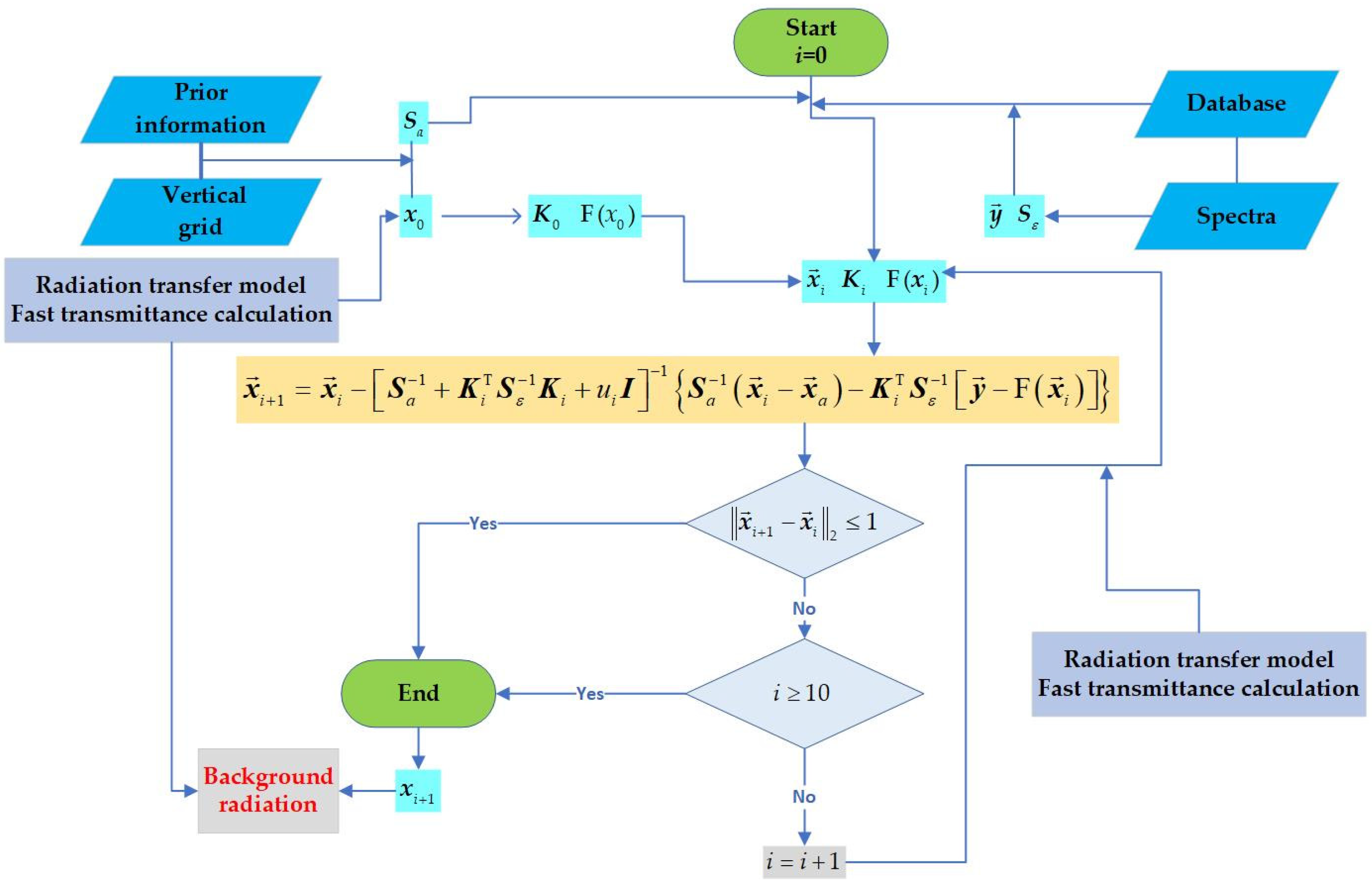
The retrieval of temperature and humidity profiles involves reverse calculations of the atmospheric state using observed values and transfer models, necessitating the solution of an implicit equation [19]. Thus, it is necessary to find the most suitable solution through iterations. In this paper, we employ the Newton iteration method, which is generally described as follows:
x i + 1 = x i 2 J x i 1 J x i ,
J x i is the cost function, represents the gradient symbol, 2 J x i also known as the Hessian matrix.
In this study, we utilized the maximum probability cost function and applied the Levenberg-Marquardt method to modify the Hessian matrix. As a result, we derived the following specific iteration formula:
x i + 1 = x i S a 1 + K i T S ε 1 K i + u i I 1 S a 1 x i x a K i T S ε 1 y F x i ,
x 0 = x a , x a is the mean value of the prior profile, and y is the observed radiance. F x i means the radiance calculated by the transfer model when the state vector is x i . S a and S ε represent the prior covariance matrix and error covariance matrix, respectively.
S a is calculated directly from prior information, whereas the S ε employs a diagonal matrix with the diagonal elements derived from the mean noise of the measured spectral data [16]. In this study, the diagonal values of the S ε are set to 0.1. The Jacobian matrix K i is recalculated for each iteration using the finite differences method. I is a unit matrix and u i represents the L-M parameter. The superscripts −1 and T represent the inverse and transpose of the matrix, respectively.
In this paper, the L-M parameter is set based on empirical knowledge. The method employed in this study is to set u i = p i + q . If the minimum eigenvalue of the Hessian matrix, denoted as σ i , is not less than zero, we p i = 0 ; otherwise, we set p i = σ i . For temperature retrieval, q = 30 , while for humidity, q = 10 5 .
The iteration process terminates when the number of iterations exceeds 10 (i > 10) or when the difference between the results of two consecutive iterations falls below a specified threshold (Equation (3)).
x i + 1 x i 2 1 ,

2.2. Vertical Grid

The vertical pressure grid used is shown in Table 1, which is consistent with the grid utilized in the Smith study [17], featuring a maximum of 50 layers. In an actual retrieval process, the lowest layer is determined based on the surface atmospheric pressure. For example, if the surface pressure is 992 hPa, the lowest layer pressure is set to 990 hPa. Conversely, if the surface pressure is 988 hPa, the lowest layer pressure is set to 980 hPa, and so on.

2.3. Prior Information

In scientific research involving temperature and humidity profile observations, equipment is typically installed at fixed observing stations. These stations regularly release radiosondes to obtain high-precision and high-vertical resolution profiles as prior information. However, it is impractical for operational applications. Therefore, we rely on the ERA5 dataset as a substitute for prior information. The ERA5 dataset is a global atmospheric reanalysis dataset that provides a comprehensive set of atmospheric variables, including temperature and humidity profiles. These profiles are derived from a combination of observations and numerical models, making the ERA5 dataset a reliable source of prior information for temperature and humidity retrieval in operational applications.
The dataset includes information across 37 pressure levels, ranging from 1000 hPa to 1 hPa, covering the entire globe with a horizontal spatial resolution of up to 0.25° × 0.25°. The prior information consists of two types of water vapor concentration data: relative humidity ( R H , %) and the mass mixing ratio ( C m , 1 , kg/kg), as well as the ozone mass mixing ratio ( C m , 2 , kg/kg). Since the concentration inputs in the transfer model are in the volume mixing ratio, a unit conversion is required.
For water vapor, the saturated vapor pressure E (hPa) at a given temperature is calculated using the Goff–Gratch equation. When the temperature t is below 273.15 K, the saturated vapor pressure is as follows [20]:
lg E = k 1 × 273.16 t 1 + k 2 × lg 273.16 t + k 3 × 1 t 273.16 + lg k 4 ,
Among them, k 1 = 9.09718 , k 2 = 3.56654 , k 3 = 0.876793 , and k 4 = 6.1071 .
When the temperature t is above 273.15 K, the formula is as follows:
lg E = k 5 × 373.16 t 1 + k 6 × lg 373.16 t + k 7 × 10 k 9 × 1 t 373.16 1 + k 8 × 10 k 10 × 373.16 t 1 1 + lg k 11
Among them, k 5 = 7.90298 , k 6 = 5.02808 , k 7 = 1.3816 × 10 7 , k 8 = 8.1328 × 10 3 , k 9 = 11.344 , k 10 = 3.49149 , and k 11 = 1013.246 .
Then, we can calculate the volume mixing ratio from E :
C v , 1 = 10 4 × R H × E / P air ,
C v , 1 represents the volume mixing ratio of water vapor, ppmv. P air is the air pressure, hPa.
For ozone, we need the average relative molecular mass of air, M air . It can be calculated using the mass mixing ratio and volume mixing ratio of water vapor, or alternatively, empirical values can be directly utilized:
M air = C v , 1 × M 1 / 10 6 × C m , 1   or   M air = 29 ,
M 1 is the relative molecular mass of water.
Then, we get the volume mixing ratio of ozone, C v , 2 , as follows:
C v , 2 = 10 6 × M air × C m , 2 / M 2 ,
M 2 is the relative molecular weight of ozone.
In this paper, we selected data from four time periods (0000 UTC, 0600 UTC, 1200 UTC, and 1600 UTC) in April each year from 2019 to 2023 in Hefei (31.9~32.1° N, 117.1~117.3° E) as prior information. A linear interpolation is required to match the prior information to the vertical pressure grid.

2.4. Spectrum and Radiation Transfer Model

2.4.1. Spectrum to Be Retrieved

The purpose of this study is to explore the feasibility of real-time acquisition of sky background radiation. Additionally, assessing the quality of the measured spectra is challenging due to potential errors introduced by instrument performance and calibration accuracy. To mitigate these errors, simulated spectra derived from gas profiles and radiation transfer models are utilized as the spectra of interest for retrieval in this study.

2.4.2. Simplified Radiation Transfer Model

Most major atmospheric components have a certain background concentration, and most trace constituents only exhibit significant absorption in the spectrum when observed at low elevation angles. Therefore, in the radiation transfer model used in this study, only 12 gases included in the US Standard Atmosphere model are considered. Before calculating the downwelling radiation, we need to make two assumptions [21]:
  • In the radiation transfer model, the atmosphere is assumed to be in thermodynamic equilibrium, allowing us to use the Planck intensity as the source function in accordance with Kirchhoff’s law.
  • The atmosphere is considered to be plane-parallel, implying that the radiance or intensity varies only in the vertical direction.
When only absorption and emission of radiation are considered, a simplified radiation transfer model can be written in the form:
I ν , θ = i = 1 N B ν , i × ( 1 τ ν , θ , i ) × τ ν , θ , i τ ν , θ , i = j = 1 i τ ν , θ , j 1 ,
In the equation, N represents the number of atmospheric layers; B ν , i indicates the blackbody radiation intensity at wavenumber ν for the i-th layer of the atmosphere at a given temperature; τ ν , θ , i denotes the transmittance along the observation direction at wavenumber ν for the i-th atmospheric layer, τ ν , θ , 0 = 1 ; τ ν , θ , i signifies the total transmittance along the observation direction at that wavenumber for all atmospheric layers below the i-th layer; and θ is the zenith Angle.
When calculating the entire layer of atmospheric downwelling radiation at the surface, the blackbody radiation intensity and emissivity 1 τ ν , θ , i of each layer are calculated first, and thus the radiation intensity B ν , i × 1 τ ν , θ , i of each layer is obtained. When the radiation of this layer is absorbed by the atmosphere with transmittance τ ν , θ , i , the radiation reaching the surface is B ν , i × 1 τ ν , θ , i × τ ν , θ , i , and the contribution of each layer can be accumulated to obtain the entire layer of atmospheric downwelling radiation at the surface.

2.4.3. Fast Transmittance Calculation

To calculate the transmittance in the radiation transfer model, we employ a simple method based on line-by-line integration. We assume that, at the same pressure, the absorption coefficient of gases at a specific wavelength has a linear relationship with temperature within a narrow range. To create a database of line-by-line absorption coefficients for various gases at different temperatures and pressures, we utilized the HAPI program [22]. In this study, the pressure conditions are consistent with the fixed vertical grid mentioned above, with a temperature range of 200 K to 320 K, at intervals of 0.5 K, and a wavenumber step of 0.1 cm−1. The maximum step size recommended by the HAPI program is 0.1 cm−1; a step size larger than this value may affect computational accuracy. There are two principles regarding the setting of the step size: (1) ensure sufficient computational accuracy, and (2) ensure that the absorption database generated from this step size does not consume excessive memory. We used the HAPI program to calculate the line-by-line absorption coefficients of 12 gases under the specified conditions, thereby establishing a database. The use of the HAPI program was strictly performed according to the manual. The program and manual can be accessed at the following URL: https://hitran.org/hapi/ (accessed on 23 September 2024)
When computing the transmittance at a specific temperature and pressure, we search the database for the absorption coefficients of twelve gases at the two temperatures closest to the desired conditions. We then interpolate these values to obtain the absorption coefficients of the gases under the required conditions and calculate their transmittance. Finally, we multiply these transmittance values to obtain the total transmittance for the mixture. For example, to determine the transmittance of CO2 at 273.15 K and 1000 hPa (which is included in the vertical grid), we simply find the absorption coefficients of CO2 at 273 K and 273.5 K under 1000 hPa and perform interpolation. We then calculate the transmittance based on the newly obtained absorption coefficients. According to the Beer–Bouguer–Lambert law, the transmittance τ is defined as follows:
τ ν , θ = exp k ν × μ θ = exp k ν × Na × P × L × C × 10 8 / t × R × cos θ
where k is the absorption coefficient, 1/(molec·cm−1); Na = 6.022141291 × 10²³, represents Avogadro’s constant; P (hPa) represents the air pressure; L (m) represents the height of gas level; C (ppmv) represents the gas concentration; t (K) represents the air temperature; and R is the ideal gas constant, R = 8.3145.

2.4.4. Simulated Spectra Correction

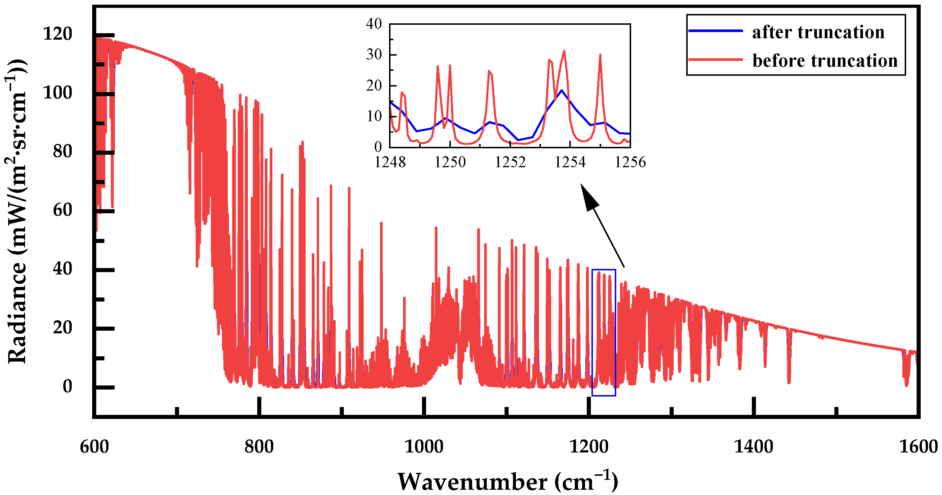
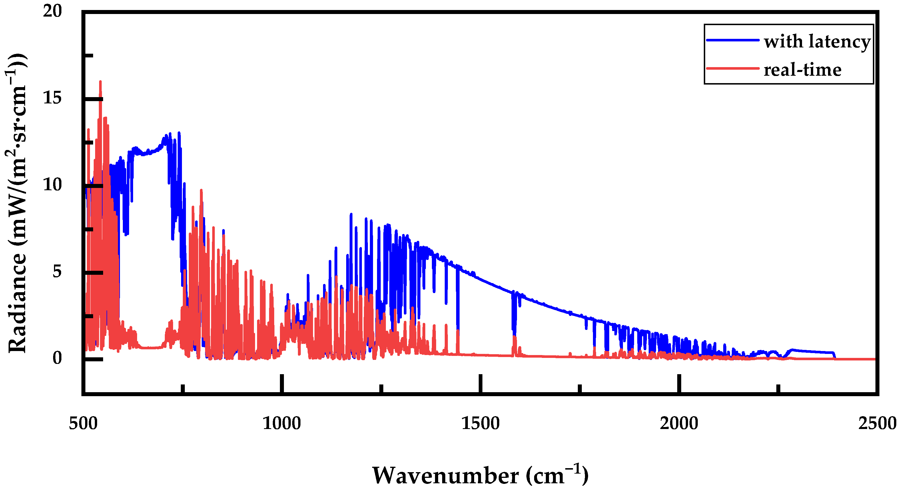
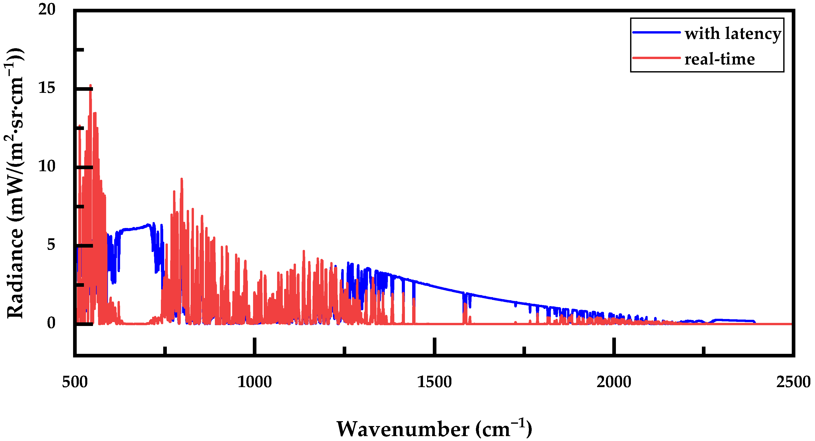
Due to the mismatch in resolution and wavenumber step between the simulated radiation spectrum calculated by the radiative transfer model and the observed spectrum, it is necessary to reconstruct the simulated spectrum. For example, with an observed spectrum resolution of 1 cm−1, the first step is to interpolate the simulated spectrum using a specific wavenumber grid. In this study, the simulated spectrum has a step size of 0.1 cm−1. After interpolation, the step size becomes 0.12055 cm−1, corresponding to a spectral resolution of 0.25 cm−1. Next, the reconstructed spectrum undergoes an Inverse Fourier Transform (IFT) to obtain an interferogram. Based on the resolution of the observed spectrum, a Hanning window function is applied to truncate the interferogram. Finally, a Fourier Transform (FT) is performed on the truncated interferogram to yield a simulated spectrum that matches the instrument’s resolution of 1 cm−1. The comparison of the simulated spectrum before and after truncation is shown in Figure 2.
Figure 3 illustrates the overall research workflow of this manuscript, along with the key functions of its subcomponents.

3. Results and Analysis

3.1. Assessment of Rapid Transmittance Calculation Accuracy

In this paper, the temperature and humidity retrieval bands are 675–712 cm−1 and 1250–1350 cm−1, respectively [17,18]. We utilized the HAPI and interpolation methods to calculate the mixed transmittance of 12 gases under 25 different conditions (combinations of 5 temperatures and 5 pressures). The temperature, pressure, and gas concentrations are listed in Table 2, with the optical path length set to 10 m.
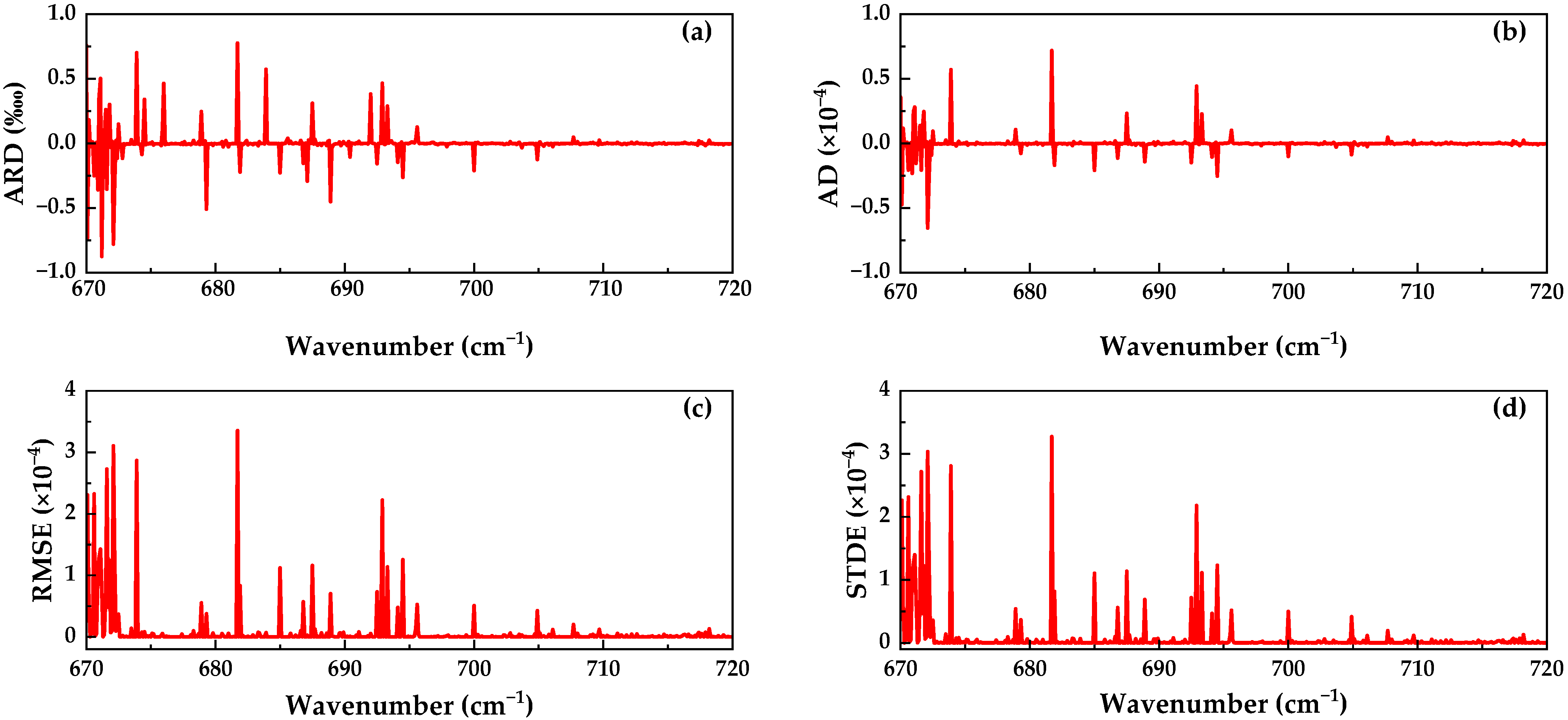
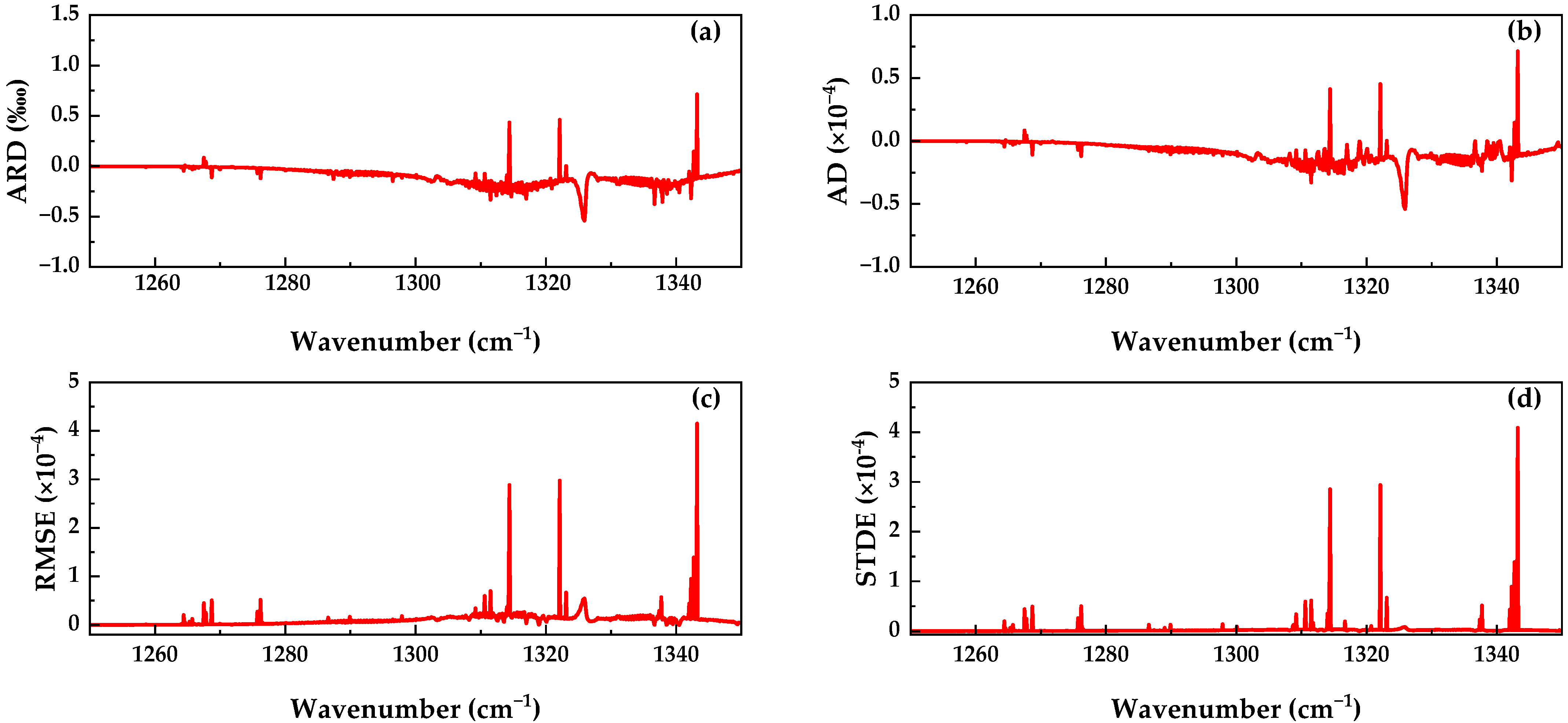
We compared the transmittance values obtained from these two methods in the respective bands and calculated the average deviation (AD), root mean square error (RMSE), and standard deviation of the errors (STDE) between them. Additionally, we computed the average relative deviation (ARD) for the corresponding bands (see Figure 4 and Figure 5).
The relative error between the transmittance calculated using the interpolation method and that obtained from the HAPI program is less than 1‱. The AD, RMSE, and STDE between the two methods are also very small, indicating that the interpolation method achieves high computational accuracy. Furthermore, the computation time for calculating a single component’s transmittance spectrum using the interpolation method does not exceed 1 s, whereas the HAPI program can take over ten seconds or even several tens of seconds. We recorded the time required for the two methods to calculate the mixed transmittance of 12 gases across different bands under 25 conditions, and the results are presented in Table 3. It indicates that the computational speed of the interpolation method is notably impressive.

3.2. Evaluation of Temperature and Humidity Profile Retrieval Accuracy

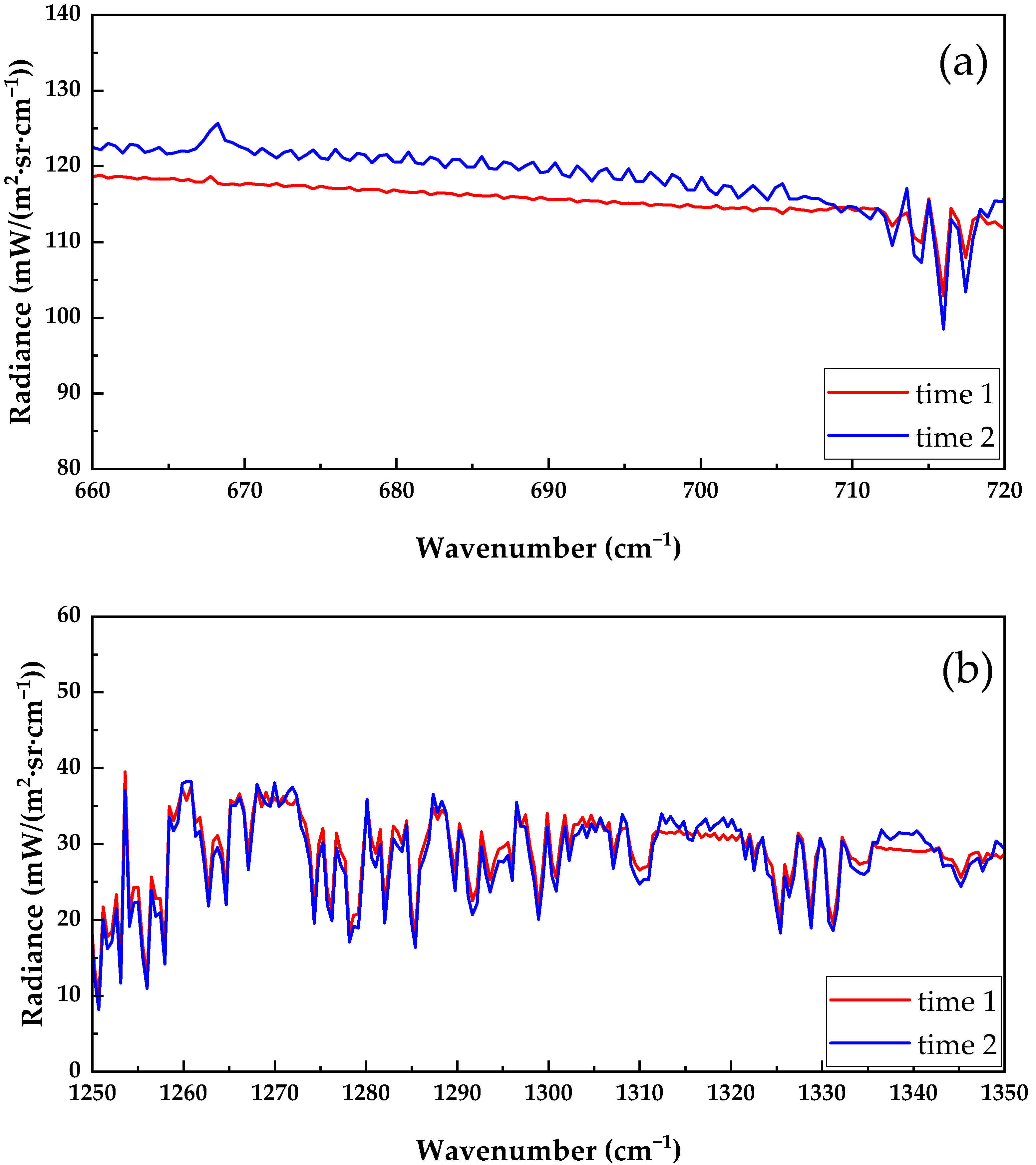
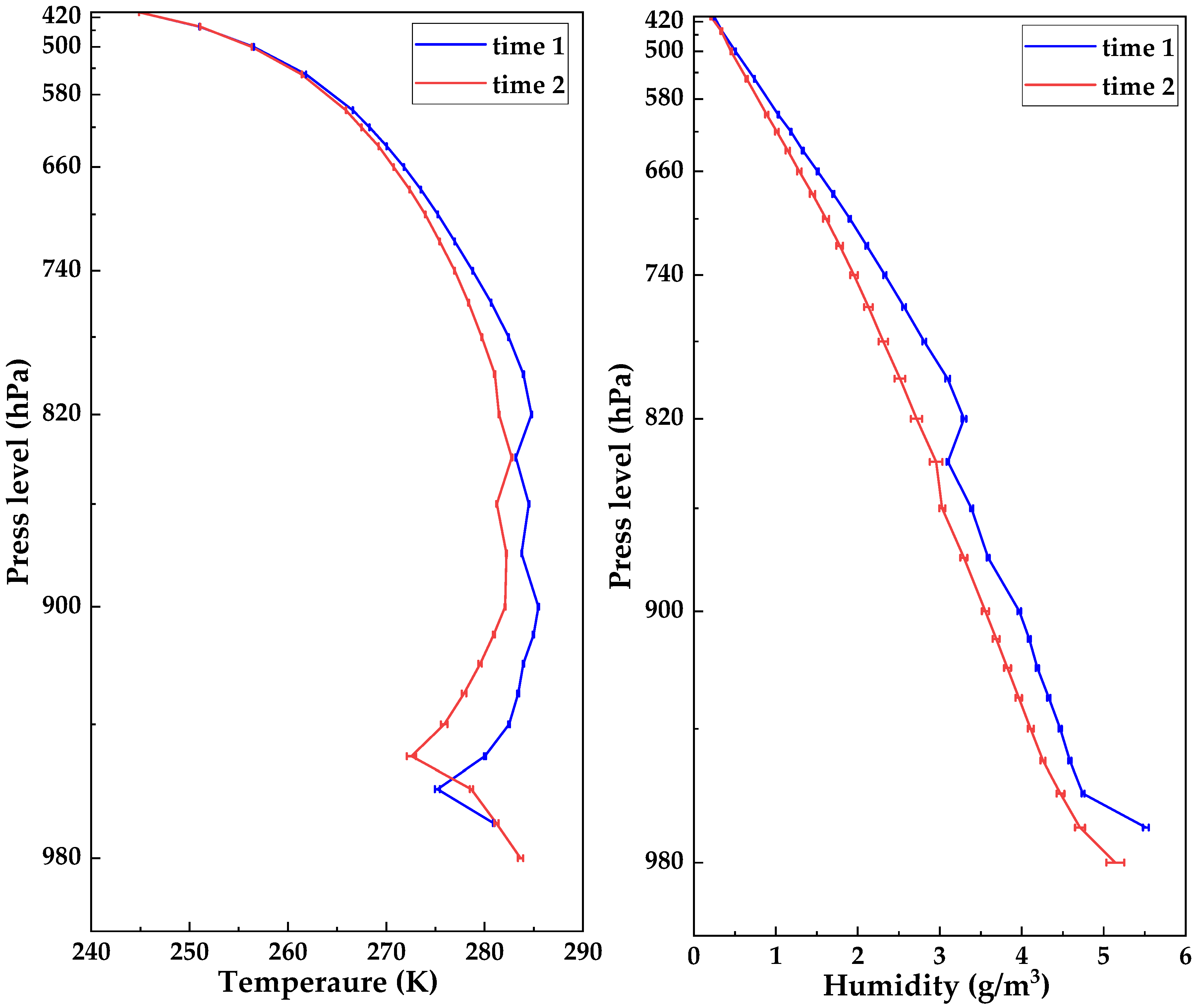
Before analyzing the accuracy of the profile retrieval, we first conducted a sensitivity analysis of the proposed method. We collected 30 consecutive spectra from two different time periods using an infrared radiometer and retrieved the temperature and humidity profiles from these spectra. As shown in Figure 6, the atmospheric environmental parameters did not change significantly during a single period, and the differences between the measured spectra were small. Therefore, there were no significant differences between the retrieval results, and the standard deviation was small (see Figure 7), indicating that the method exhibits a certain degree of stability. On the other hand, the profiles retrieved from spectra measured at different times showed differences, indicating that the method is highly sensitive to changes in the environment.
We obtained hourly ERA5 data from the ECMWF website for 1st, 2nd, 7th, and 8th April 2024, totaling 96 sets of data [23]. Following the method outlined in Section 2, we extracted the temperature, water vapor, and ozone profiles from these data. We then obtained average profiles for 10 additional gases from a website provided by James Hannigan (ftp://nitrogen.acom.ucar.edu/user/jamesw/IRWG/2021/WACCM.v7/Hefei.V7/, accessed on 1 September 2024) and interpolated them onto the vertical grid shown in Table 1. A simplified atmospheric model was established (see Appendix A), where temperature and water vapor were considered variable, while the other gases were treated as constant.
The retrieval of temperature and humidity is performed sequentially. In the temperature retrieval process, the temperature profile is treated as a variable while keeping the other parameters constant. The water vapor and ozone profiles are set to the average values of the priori profiles, and the other parameters are set according to Appendix A. In the humidity retrieval process, the humidity profile is treated as a variable, while the temperature profile is set to the values retrieved in the temperature retrieval step. The remaining parameters are kept the same as in the temperature retrieval process.
Based on the aforementioned 96 sets of data, we performed simulation calculations to obtain 96 radiative spectra. These spectra were then used for fast retrieval of temperature and humidity profiles. Subsequently, we conducted an analysis and evaluation of the retrieval results. It is worth mentioning that with the use of the rapid retrieval method, the average time required to obtain a temperature profile and a humidity profile does not exceed 5 min, which fully meets the requirements for engineering applications.
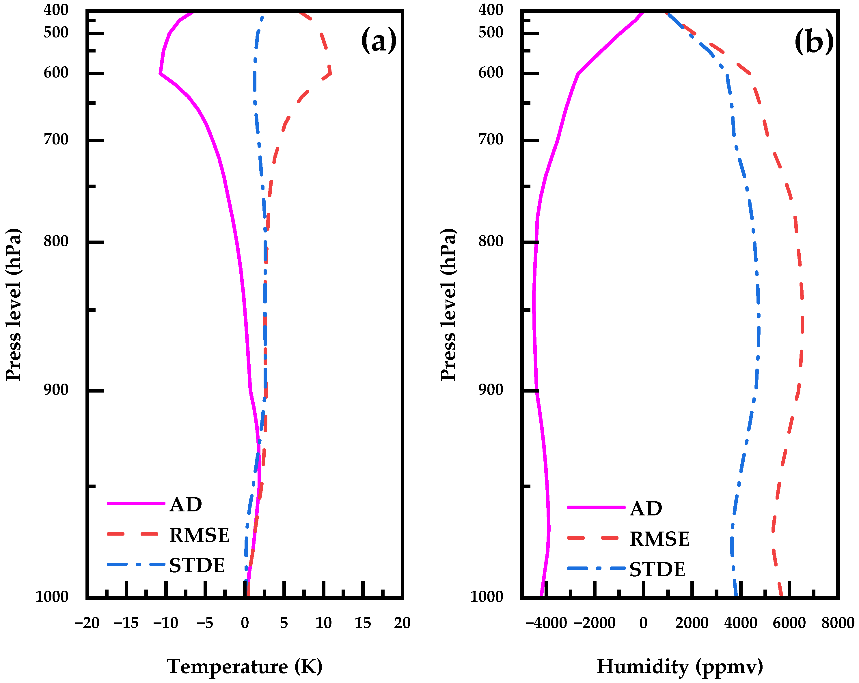
Figure 8 presents the average deviation (AD), root mean square error (RMSE), and standard deviation of the errors (STDE) for the temperature and humidity profile retrieval results compared to the theoretical values. For temperature retrieval, the difference between the retrieval results and the theoretical values is relatively small near the surface but increases with altitude. Previous studies have indicated that retrieval accuracy is noticeably higher below the boundary layer than above it, which aligns with our expectations for the rapid temperature profile retrieval results.
In contrast, for humidity retrieval, we observed a significant difference throughout the entire altitude range. On one hand, due to the saturation of water vapor absorption, the retrieval results tend to be significantly lower than the true values when humidity is high. On the other hand, it is possible that the method used in this study itself introduces substantial errors in humidity retrieval; however, we are currently unable to pinpoint the exact source of these errors.

3.3. Evaluation of Sky Background Radiation Simulations

As mentioned earlier, the current method based on simulated atmospheric background radiation has some latency. To demonstrate the real-time advantage of the rapid retrieval method for obtaining atmospheric background radiation, we used 48 simulated spectra corresponding to the data from 7 and 8 April 2024, as hypothetical measured spectra. We considered the ECMWF results from 1 and 2 April as the input with latency, while the retrieval results from the 7 and 8 April spectra served as the input with real-time information. By comparing the differences between the sky background radiation obtained from these two parameter inputs and the hypothetical measured spectra, we can highlight the advantage of real-time retrieval of sky background radiation using the rapid retrieval method.
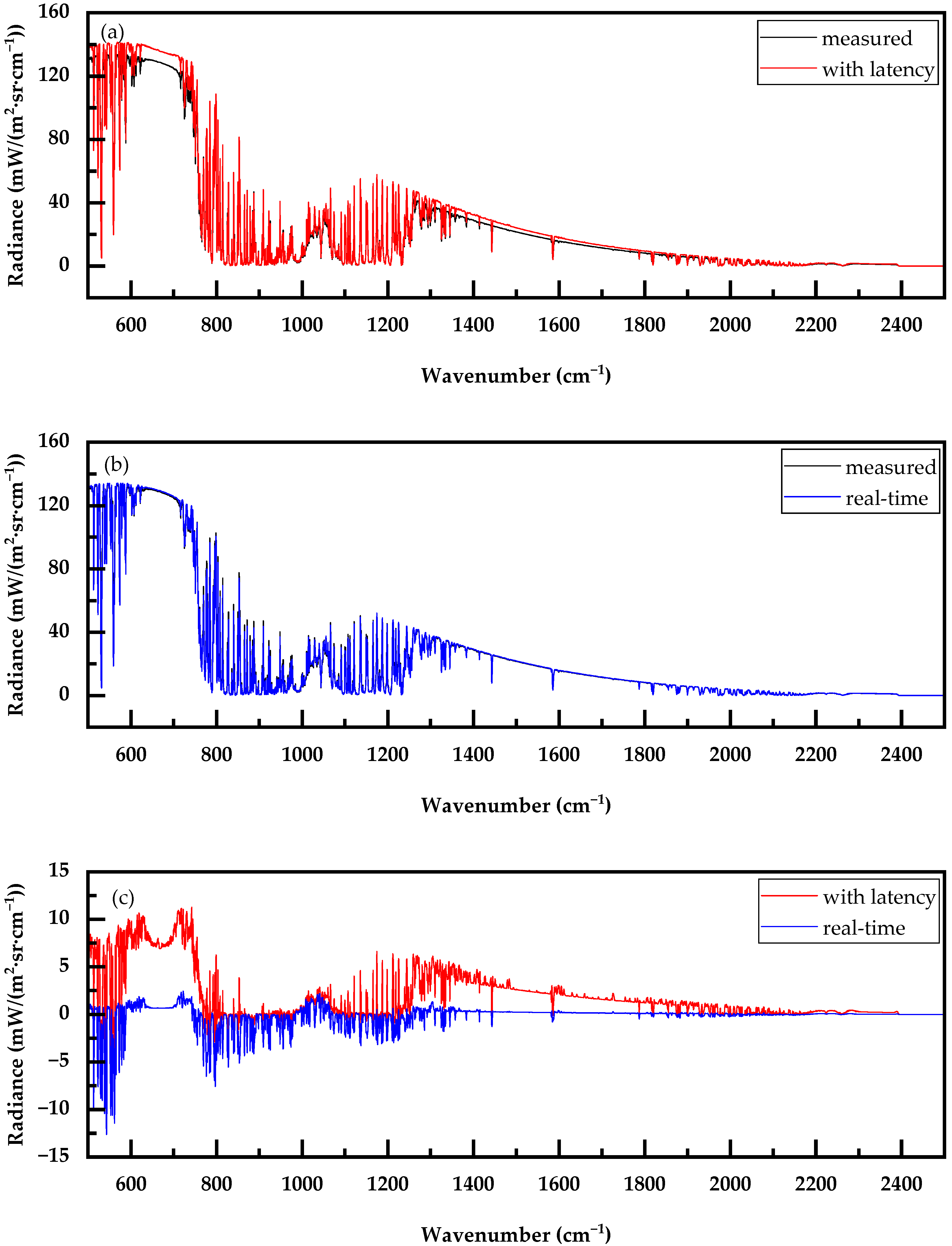
We calculated the deviations, RMSE, and STDE for the two sets of 48 sky background radiation spectra compared to the hypothetical measured spectra. From Figure 9 and Figure 10, it is evident that the RMSE and STDE of the sky background radiation calculated using the rapid retrieval method with real-time input profiles are significantly lower than those obtained using the latest profiles provided by ECMWF ERA5. Figure 11 illustrates the sky background radiation calculated by both methods at a specific time. It is visually apparent that the background radiation obtained using the rapid retrieval method is more reasonable and closer to the hypothetical measured spectra.

4. Conclusions and Discussion

At present, researchers mainly acquire sky background radiation for application in infrared remote sensing in two ways. The first method is to periodically collect and update the background spectrum in the monitoring application process, which is simple to operate but will interrupt the monitoring process. Therefore, the second method is derived to simulate the background radiation based on the atmospheric parameter profile and transmission model. This method can update the background spectrum in the monitoring process, but there is a lag problem in obtaining the atmospheric parameter profile. In order to solve this problem, based on the theoretical framework of the existing infrared remote sensing technology, we simplified the retrieval method of temperature and humidity profiles, focused on the transmission calculation and transmission model, and established a fast and real-time method to obtain the sky background radiation.
The fast transmittance calculation method utilizing line-by-line integration and interpolation principles significantly improves computational speed while maintaining high accuracy compared to the HAPI program. Additionally, the simplified transmission model, which incorporates 12 gas components, is sufficient for simulating background radiation. With this new method, we can rapidly extract temperature and humidity profile information corresponding to the measured spectra and obtain the associated background spectra. Compared to extracting the latest profiles from datasets, the new method shows smaller differences between the calculated background radiation and measured spectra, making it more suitable for calculating sky background radiation.
Furthermore, we compare the differences between the retrieval results of the profiles and the true values. The results show a certain level of accuracy in temperature retrieval of the lower atmosphere, but the humidity retrieval results are not ideal. In addition, the current method can only be applied to clear sky conditions, and cannot be effectively processed for clouds. Considering that this temperature and humidity fast retrieval method does not require high hardware and software requirements, we plan to conduct further research on the accuracy of humidity and cloud retrieval in the follow-up work. We hope that this fast retrieval method can be widely applied in temperature and humidity profile observation applications and scientific research.

Author Contributions

Conceptualization, S.S. and L.X.; Formal analysis, S.S. and L.X.; Funding acquisition, J.L. and L.X.; Methodology, S.S.; Resources, J.L. and L.X.; Software, S.S., Y.W. and Y.S.; Validation, Y.D.; Writing—original draft, S.S.; Writing—review and editing, S.S. and L.X. All authors have read and agreed to the published version of the manuscript.

Funding

This project is supported by the key R&D program of Anhui Province, grant number 2022m07020009, and the National Natural Science Foundation of China, grant number 52027804.

Institutional Review Board Statement

Not applicable.

Informed Consent Statement

Not applicable.

Data Availability Statement

The original contributions presented in the study are included in the article, further inquiries can be directed to the corresponding author.

Acknowledgments

The authors would like to thank the European Centre for Medium-Range Weather Forecasts and the Infrared Working Group for sharing the basic research data. We also would like to thank anonymous reviewers for their insightful comments and constructive suggestions.

Conflicts of Interest

The authors declare no conflicts of interest.

Appendix A

Table A1. The pressure (P, hPa), height (H, m), and concentration (ppmv) of gases in each layer of the model atmosphere.
PHCO2CH4CO
(×10−1)
N2O
(×10−1)
HNO3
(×10−3)
NH3
(×10−3)
NO
(×10−3)
NO2
(×10−3)
O2
(×105)
SO2
(×10−3)
100050402.781.941.963.251.084.231.597.5521.114.51
990150402.741.931.853.251.193.801.386.5921.114.00
980300402.701.931.743.251.083.381.175.6321.113.49
970420402.671.931.633.251.192.950.964.6721.112.98
960530402.631.921.523.251.302.520.753.7121.122.48
950600402.591.921.413.251.402.090.552.7521.121.97
940710402.551.921.303.251.511.660.341.7921.121.46
930810402.511.911.193.251.621.230.130.8321.120.95
920900402.501.911.173.251.541.140.110.7321.120.87
9101000402.491.911.143.251.461.050.090.6221.120.79
9001100402.471.911.113.251.380.950.070.5121.120.71
8801280402.451.911.063.251.230.770.040.2921.130.54
8601460402.441.901.023.251.090.670.030.2321.130.47
8401660402.431.900.993.250.950.570.020.1721.130.39
8201860402.421.900.963.250.830.490.020.1221.140.33
8002080402.421.900.943.250.730.430.010.1121.140.29
7802280402.421.890.913.250.630.360.010.0921.140.25
7602500402.441.890.903.250.560.310.010.0721.150.22
7402720402.461.890.883.250.490.260.010.0721.150.19
7202940402.491.890.863.250.420.220.010.0621.160.16
7003180402.541.890.853.250.380.180.010.0521.160.14
6803420402.591.890.843.260.330.150.010.0521.170.12
6603650402.641.890.823.260.290.120.010.0421.170.10
6403900402.691.880.813.260.270.100.010.0421.170.09
6204150402.741.880.803.260.240.080.010.0421.180.07
6004420402.791.880.803.260.230.070.010.0421.180.06
5505120402.921.880.783.260.200.040.010.0421.190.04
5005860403.041.880.773.260.190.030.010.0421.200.03
4506670403.091.880.773.260.230.020.010.0521.200.02
4007550403.071.870.773.260.270.020.020.0621.210.02
3508540402.961.870.763.260.320.020.030.0721.210.02
3009630402.741.870.753.260.360.020.040.0921.210.02
25010,880402.371.860.713.250.450.010.060.1121.210.02
20012,380401.781.850.623.230.630.010.080.1221.220.02
17513,250401.451.830.553.220.750.010.080.1321.220.02
15014,230401.141.820.473.190.890.010.090.1321.230.02
12515,350400.931.810.393.171.040.000.100.1621.230.02
10016,720400.641.790.313.121.350.000.130.2121.230.03
7518,410399.671.730.212.992.250.000.170.3321.230.07
5020,850396.891.550.132.555.010.000.270.6921.230.09
3024,090394.461.320.151.887.710.000.621.9121.230.02
2525,250394.041.250.161.677.850.000.852.6521.220.02
2026,720393.691.170.171.427.350.001.273.8521.220.02
1528,600393.451.070.191.125.910.002.045.7021.220.02
1031,320393.320.960.220.793.550.003.378.1021.220.02
733,800393.310.880.260.571.920.004.599.3921.220.01
536,160393.330.810.310.420.960.005.679.7221.220.01
437,840393.340.760.340.350.590.006.389.5121.220.01
340,000393.350.700.380.270.290.007.149.0021.220.02
243,100393.330.600.440.180.090.007.727.9221.220.03

References

  1. Capodaglio, A.G. Developments and Issues in Renewable Ecofuels and Feedstocks. Energies 2024, 17, 3560. [Google Scholar] [CrossRef]
  2. Wu, M.; Liu, W.; Ma, Z.; Qin, T.; Chen, Z.; Zhang, Y.; Cao, N.; Xie, X.; Chi, S.; Xu, J.; et al. Global Trends in the Research and Development of Petrochemical Waste Gas from 1981 to 2022. Sustainability 2024, 16, 5972. [Google Scholar] [CrossRef]
  3. Zhao, Q.; Nie, X.X.; Luo, D.; Wang, J.; Li, Q.R.; Chen, W. An Effective Method for Gas-Leak Area Detection and Gas Identification with Mid-Infrared Image. Photonics 2022, 9, 992. [Google Scholar] [CrossRef]
  4. Rodriguez-Conejo, M.A.; Melendez, J.; Barber, R.; Garrido, S. Design of an Infrared Imaging System for Robotic Inspection of Gas Leaks in Industrial Environments. Int. J. Adv. Robot. Syst. 2015, 12, 23. [Google Scholar] [CrossRef]
  5. Hu, Y.Y.; Xu, L.; Xu, H.Y.; Shen, X.C.; Deng, Y.S.; Xu, H.Y.; Liu, J.G.; Liu, W.Q. Three-dimensional reconstruction of a leaking gas cloud based on two scanning FTIR remote-sensing imaging systems. Opt. Express 2022, 30, 25581–25596. [Google Scholar] [CrossRef] [PubMed]
  6. Hu, Y.Y.; Xu, L.; Shen, X.C.; Jin, L.; Xu, H.Y.; Deng, Y.S.; Liu, J.G.; Liu, W.Q. Reconstruction of a leaking gas cloud from a passive FTIR scanning remote-sensing imaging system. Appl. Opt. 2021, 60, 9396–9403. [Google Scholar] [CrossRef] [PubMed]
  7. Donato, P.; Barres, O.; Sausse, J.; Taquet, N. Advances in 3-D infrared remote sensing gas monitoring. Application to an urban atmospheric environment. Remote Sens. Environ. 2016, 175, 301–309. [Google Scholar] [CrossRef]
  8. Kastek, M.; Piatkowski, T.; Trzaskawka, P. Infrared Imaging Fourier Transform Spectrometer as the Stand-Off Gas Detection System. Metrol. Meas. Syst. 2011, 18, 607–620. [Google Scholar] [CrossRef]
  9. Stremme, W.; Krueger, A.; Harig, R.; Grutter, M. Volcanic SO2 and SiF4 visualization using 2-D thermal emission spectroscopy–Part 1: Slant-columns and their ratios. Atmos. Meas. Tech. 2012, 5, 275–288. [Google Scholar] [CrossRef]
  10. Kang, R.Y.; Liatsis, P.; Kyritsis, D.C. Emission Quantification via Passive Infrared Optical Gas Imaging: A Review. Energies 2022, 15, 3304. [Google Scholar] [CrossRef]
  11. Wu, S.P.; Zhong, X.; Qu, Z.; Wang, Y.H.; Li, L.; Zeng, C.L. Infrared Gas Detection and Concentration Inversion Based on Dual-Temperature Background Points. Photonics 2023, 10, 490. [Google Scholar] [CrossRef]
  12. Hu, Y.Y.; Xu, L.; Shen, X.C.; Shu, S.Q.; Xu, H.Y.; Deng, Y.S.; Xu, H.Y.; Liu, J.G.; Liu, W.Q. Inversion method of target gas cloud transmittance based on atmospheric profile synthesis background. Acta Phys. Sin. 2023, 72, 033201. [Google Scholar] [CrossRef]
  13. Knuteson, R.; Revercomb, H.; Best, F.; Ciganovich, N.; Dedecker, R.; Dirkx, T.; Ellington, S.; Feltz, W.; Garcia, R.; Howell, H.; et al. Atmospheric Emitted Radiance Interferometer. Part I: Instrument Design. J. Atmos. Ocean. Technol. 2004, 21, 1763–1776. [Google Scholar] [CrossRef]
  14. Knuteson, R.; Revercomb, H.; Best, F.; Ciganovich, N.; Dedecker, R.; Dirkx, T.; Ellington, S.; Feltz, W.; Garcia, R.; Howell, H.; et al. Atmospheric Emitted Radiance Interferometer. Part II: Instrument Performance. J. Atmos. Ocean. Technol. 2004, 21, 1777–1789. [Google Scholar] [CrossRef]
  15. Zhao, H.J.; Ma, X.H.; Jia, G.R.; Mi, Z.Y.; Ji, H.L. Synergistic Retrieval of Temperature and Humidity Profiles from Space-Based and Ground-Based Infrared Sounders Using an Optimal Estimation Method. Remote Sens. 2022, 14, 5256. [Google Scholar] [CrossRef]
  16. Löhnert, U.; Turner, D.D.; Crewell, S. Ground-Based Temperature and Humidity Profiling Using Spectral Infrared and Microwave Observations. Part I: Simulated Retrieval Performance in Clear-Sky Conditions. J. Appl. Meteorol. Climatol. 2009, 48, 1017–1032. [Google Scholar] [CrossRef]
  17. Smith, W.L.; Feltz, W.E.; Knuteson, R.O.; Revercomb, H.E.; Woolf, H.M.; Howell, H.B. The retrieval of planetary boundary layer structure using ground-based infrared spectral radiance measurements. J. Atmos. Ocean. Technol. 1999, 16, 323–333. [Google Scholar] [CrossRef]
  18. Feltz, W.F.; Smith, W.L.; Knuteson, R.O.; Revercomb, H.E.; Woolf, H.M.; Howell, H.B. Meteorological applications of temperature and water vapor retrievals from the ground-based Atmospheric Emitted Radiance Interferometer (AERI). J. Appl. Meteorol. 1998, 37, 857–875. [Google Scholar] [CrossRef]
  19. Rodgers, C. Optimal Methods for Non-linear Inverse Problems. In Inverse Methods for Atmospheric Sounding: Theory and Practice; Taylor, F.W., Ed.; World Scientific: London, UK, 2000; Volume 2, pp. 81–99. [Google Scholar]
  20. Zhou, X.H.; Liang, Y.; Wang, X.M.; Zhou, L.C. Comparison of saturation vapor pressure formulas. J. Liaoning Tech. Univ. 2007, 26, 331–333. [Google Scholar]
  21. Liou, K. Thermal Infrared Radiation Transfer in the Atmosphere. In An Introduction to Atmospheric Radiation, 2nd ed.; Dmowska, R., Holton, J.R., Rossby, H.T., Eds.; Academic Press: San Diego, CA, USA, 2002; Volume 84, pp. 122–127. [Google Scholar]
  22. Kochanov, R.V.; Gordon, I.; Rothman, L.; Wcisło, P.; Hill, C.; Wilzewski, J. HITRAN Application Programming Interface (HAPI): A comprehensive approach to working with spectroscopic data. J. Quant. Spectrosc. Radiat. Transf. 2016, 177, 15–30. [Google Scholar] [CrossRef]
  23. Hersbach, H.; Bell, B.; Berrisford, P.; Biavati, G.; Horányi, A.; Muñoz Sabater, J.; Nicolas, J.; Peubey, C.; Radu, R.; Rozum, I.; et al. ERA5 Hourly Data on Pressure Levels from 1940 to Present. Copernicus Climate Change Service (C3S) Climate Data Store (CDS). Available online: https://cds.climate.copernicus.eu/cdsapp#!/dataset/10.24381/cds.bd0915c6?tab=overview (accessed on 23 June 2024).
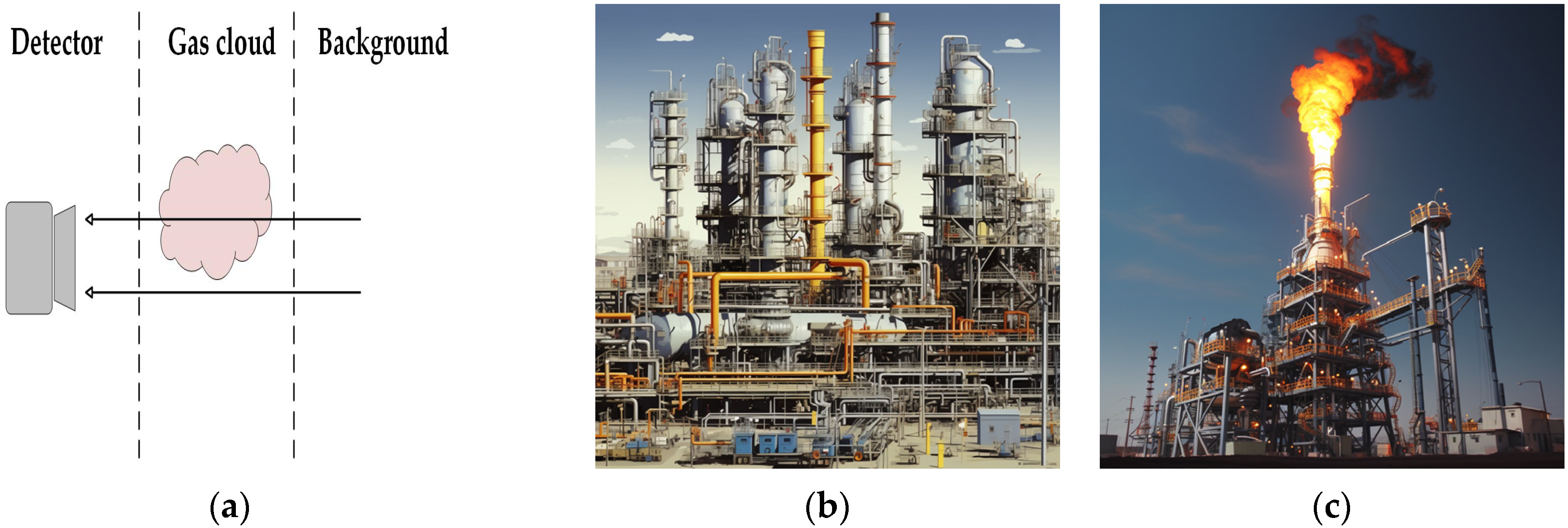
Figure 1. Three-layer radiation transmission model and different monitoring backgrounds: (a) three-layer radiation transmission model; (b) ground object background; (c) sky background.
Photonics 11 00904 g001
Figure 2. Comparison of the simulated spectra before and after truncation.
Photonics 11 00904 g002
Figure 3. Schematic of the research.
Photonics 11 00904 g003
Figure 4. The ARD (a), AD (b), RMSE (c), and ATDE (d) between the transmittance values obtained from the two methods in the temperature retrieval band.
Photonics 11 00904 g004
Figure 5. The ARD (a), AD (b), RMSE (c), and ATDE (d) between the transmittance values obtained from the two methods in the humidity retrieval band.
Photonics 11 00904 g005
Figure 6. Average spectra measured during the two time periods: (a) temperature retrieval band; and (b) humidity retrieval band.
Photonics 11 00904 g006
Figure 7. Comparison of the retrieval results of the spectra measured over different time periods.
Photonics 11 00904 g007
Figure 8. The AD, RMSE, and STDE of temperature (a) and humidity (b) retrievals.
Photonics 11 00904 g008
Figure 9. The RMSE between the measured spectra and the two types of background radiation spectra. Blue line: background radiation calculated with the hysteresis profile provided by ERA5 as the input parameter; red line: background radiation calculated with the real-time profile obtained by the fast retrieval method as the input parameter.
Photonics 11 00904 g009
Figure 10. As in Figure 9 but for STDE.
Photonics 11 00904 g010
Figure 11. The difference between the measured spectra and the two types of background radiation spectra at 0:00 UTC on 7th April 2024: (a) background radiation with latency; (b) background radiation in real-time; (c) bias of two types of background radiation spectra with measured spectra.
Photonics 11 00904 g011
Table 1. Vertical pressure (in hPa) grid used in profile retrieval.
1000950900800700600350150307
990940880780680550300125255
980930860760660500250100204
97092084074064045020075153
96091082072062040017550102
Table 2. Temperature, pressure, and gas concentrations used in the assessment of rapid calculation accuracy of transmittance.
Temperature (K)Pressure (hPa)Gas Concentrations (ppmv)
270.11000CO2: 400O2: 210000
272.3900H2O: 10000NH3: 0.0042
274.5800CH4: 1.90NO: 0.0016
276.7700CO: 0.20NO2: 0.0060
278.9600N2O: 0.33SO2: 0.0045
O3: 0.03HNO3: 0.0011
Table 3. Comparison of calculation speeds of the two methods.
Total Time Taken (s)
Calculation Bands (cm−1)HAPIInterpolation Method
672–71589837.5
1250–1350115135
500–2500311837.5
Disclaimer/Publisher’s Note: The statements, opinions and data contained in all publications are solely those of the individual author(s) and contributor(s) and not of MDPI and/or the editor(s). MDPI and/or the editor(s) disclaim responsibility for any injury to people or property resulting from any ideas, methods, instructions or products referred to in the content.