Article

Application of Micro-Tubing Reeling System to Serial Femtosecond Crystallography

1
Department of Life Sciences, Pohang University of Science and Technology, Pohang 37673, Republic of Korea
2
Pohang Accelerator Laboratory, Pohang University of Science and Technology, Pohang 37673, Republic of Korea
*
Author to whom correspondence should be addressed.
These authors contributed equally to this work.
Photonics 2024, 11(1), 95; https://doi.org/10.3390/photonics11010095
Submission received: 19 December 2023 / Revised: 15 January 2024 / Accepted: 20 January 2024 / Published: 22 January 2024
(This article belongs to the Special Issue XUV and X-ray Free-Electron Lasers and Applications)

Abstract

:
Microcrystal delivery instruments are pivotal to performing serial femtosecond crystallography experiments at the XFEL facilities. We present a novel sample delivery technique based on a micro-tubing reeling system (MRS). Despite the tiny size of the micro-tubing, the MRS device has the advantage of operating without real-time position adjustment of the tube to match with the XFEL pulses. Moreover, the applicable repetition rate is more flexible than the previously reported chip-based one-dimensional fixed target system.

1. Introduction

X-ray free-electron laser (XFEL) sources have enabled the revealing of various macromolecular structures based on the “diffraction before destruction” scheme [1]. The three-dimensional electron-density map can be obtained at room temperature with quite a low radiation damage effect through serial femtosecond crystallography (SFX) [2,3,4,5]. To perform SFX, micron-sized crystals should be continuously placed at the XFEL interaction point.
For this purpose, various attempts have been made to develop sample delivery techniques such as liquid jet with a gas-dynamic virtual nozzle [6,7], lipidic cubic phase (LCP) injection [8,9], fixed-sample scanning [10,11,12], sandwiched thin films [13,14,15], concentric MESH (microfluidic electrokinetic sample holder) [16], and drop on a tape [17]. The summarized contents also can be found in a review paper [18].
In a similar context, there have been several attempts at sample delivery in serial synchrotron crystallography. The capillary-based microfluidic device, which is a combination of several layers, can be a technique for high-throughput screening and diffraction data collection [19]. High-viscosity extruder injectors [20,21] and tape-drive methods [22,23] have been successfully demonstrated at the synchrotron facilities.
The key requirements for sample delivery are sample consumption, stable transport, and prevention of dehydration during the SFX experiments. Liquid jet and LCP injections are advantageous for lower background scattering and slower sample delivery speed, respectively. However, they have drawbacks with the high sample consumption for liquid jet and high background scattering from the viscous media for LCP. The approach of using thin films has merit in simpler sample preparation and delivery but still requires additional efforts to achieve viscous environments or the attachment of two thin films to prevent sample dehydration. On the other hand, the one-dimensional fixed target utilizing micro-tubing takes strong points of previous techniques like a low background scattering intensity, a controllable delivery speed related to sample consumption, and a quick closing process for keeping almost a perfect hydration condition.
In previous research, we have reported a chip-based one-dimensional fixed target system, which consists of a two-dimensional array of microcrystal containers (MCCs) [24]. A single chip holds four MCCs, and the inner and outer diameters (ID, OD) and lengths of the MCCs are 100 μm, 126 μm, and 500 mm, respectively. The sample, usually a solution of protein microcrystals, is inserted into the MCCs, and XFEL pulses are illuminated on the tubing with the raster scanning method. The MCCs facilitate less sample consumption than the two-dimensional fixed target and a long-lasting humid condition. From the instrumentation point of view, due to the micron-sized tube diameter, the illumination on the tube by the XFEL pulses can be missed even for a tiny angular misalignment during a scan. To clear this alignment issue, we have embedded a position feedback control via a real-time visual servo method. However, this operational scheme has a limitation on the applicable XFEL repetition rate owing to the time lag originating from real-time image processing to identify the positions of the MCCs and the immediate movement of the MCCs to the aimed XFEL position. Here, we report a novel micro-tubing-based sample delivery system called a micro-tubing reeling system. It has advanced features of a simplified XFEL beam-alignment process without the real-time position feedback.

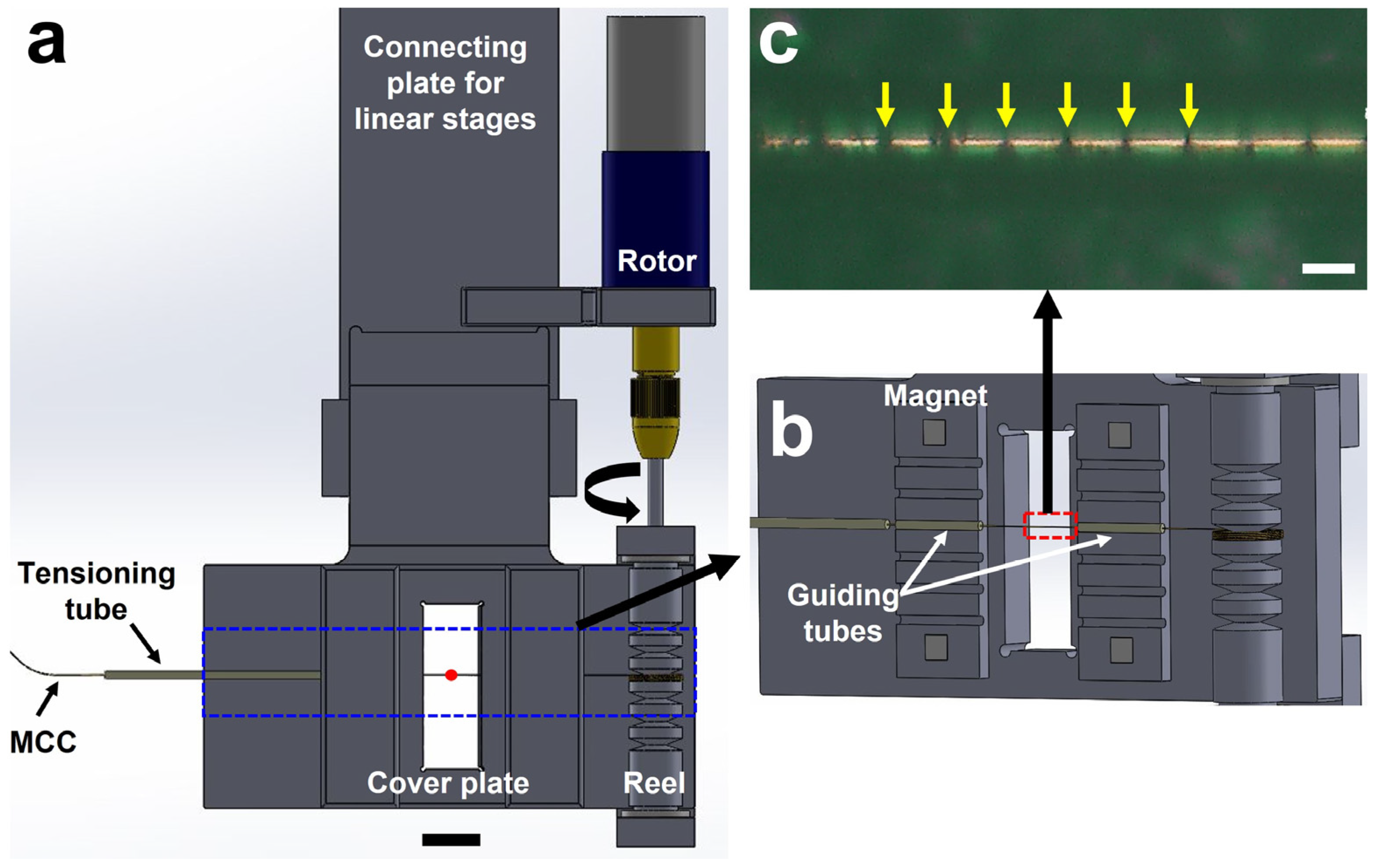
2. Micro-Tubing Reeling System

The micro-tubing reeling system (MRS) is a novel instrument to deliver microcrystals to the X-ray interaction point for serial crystallography experiments at the synchrotron and XFEL facilities. Figure 1a shows the drawing of the MRS system and components. Different from the previous operation scheme based on a fixed frame, the position of the MCC, which is a micro-tubing container holding microcrystals inside, is controlled by winding it to a reel. It is designed to have the MCC, a single mini-rotor, two tube guides, and a tensioner tube. The mini-rotor is a two-phase stepping motor (Microservo Encoding-Motor PGM22-2028E). The first preparation step before loading the sample on the MCC involves stringing three pieces of PEEK tubing (Part No. 1531, IDEX Health and Science) on the polyimide micro-tubing (length: 1000 mm, ID: 100 μm, thickness: 13 μm; Nordson Corp.), working as the MCC. The ID and the OD of the PEEK tubes are 0.01 and 1/16 in., respectively. The two short PEEK tubing pieces are about 15 mm in length each, and the other piece is about 45 mm. Here, the two shorter and the one longer PEEK tubing pieces are used as the MCC traveling guide and the tensioner, respectively (Figure 1b). The two short lengths of PEEK tubing are placed in a groove and held in place by four magnets attached to the cover plate.
A sample, such as microcrystals suspended solution, is inserted into the MCC. A commercial fast-drying glue (LOCTITE® 401) is used to close both sides of the MCC. This MCC-based sample delivery technique can control the delivery speed matching the PAL-XFEL repetition rate. However, it does not cause clogging, which can be encountered when using liquid jet or LCP injectors.
Generally, the tension control makes it tricky to achieve a stable delivery like a conveyor belt. Most of the tension control system is not straightforward. Several kinematic designs are usually employed to make a proper tension level. The damping wheel, the compensation body, and the dancing lever schemes are mostly used to maintain the tension level. They require various pullies and translational stages to keep the continuous reeling motion [25].
On the other hand, the MRS has a simpler tension structure than prototypical schemes that are controlled by pullies and translational stages. The tension is provided by the interaction between the MCC and the tensioner tube, which is made of a short piece of PEEK tubing with a length, ID, and OD of about 40 mm, 0.01″, and 1/16″, respectively. The tension comes from the resistance of the MCC motion with the curvature of the PEEK tubing. The radius of the curvature was about 160 mm. Under this geometry, the delivery motion is very stable during the data collection (Supplementary Video S1).
Sample loading on the MCC is exactly the same as the methods described in our previous study [24]. The needle of the syringe that contains the mixed crystal solution is connected with the MCC by a union fitting. Both ends of the MCC are closed with a fast-drying glue to maintain humidity during handling and experiments. To install the prepared MCC on the MRS system, one end of the MCC is attached to the reeling parts with adhesive tapes and closed with the cover frame. The cover frame of the reel also has a magnetic mount for a quick installation.

3. Experiments and Results

3.1. Experimental Conditions and Data Acquisition

We have performed the SFX experiments to verify the application of the MRS sample delivery at the NCI experimental station, PAL-XFEL (Pohang Accelerator Laboratory X-ray Free-Electron Laser, Pohang, South Korea) [26,27,28]. The wavelength, pulse duration, and photon flux for the incident XFEL were 1.0 Å, <~25 fs, and ~2 × 10¹¹ photons per pulse, respectively. The repetition rate was 30 Hz. The bandwidth of XFEL is approximately 0.2%. The focused beam size delivered by the Kirkpatrick–Baez mirrors was approximately 5 × 5 μm2 at the sample position [29]. The diffraction images were collected with an MX225-HS detector (Rayonix, LLC, Evanston, IL, USA) at a distance of about 150 mm from the sample position. The 4 × 4 binning mode was utilized for the detector to match the incident XFEL repetition rate of 30 Hz. The hen egg-white (HEW) lysozyme microcrystals have been used as a model sample without additional carrier matrix media. The crystal size was about 5 × 5 × 5 μm3. The sample consumption for the whole data collection was about 50 μL.

3.2. Operation of the MRS

The MRS is installed and can be operated in the MICOSS (Multifarious injection chamber for molecular structure study), an SFX-dedicated sample chamber established to operate various types of injectors at the PAL-XFEL [30]. Figure 2 shows the photos of the MRS and the installed geometry inside the MICOSS. The position of the MRS is manipulated with three-axis linear stages [30]. The mini-rotor of the MRS is remotely controlled through a feedthrough, which makes a connection between the two-phase stepping motor and the customized controller. The angle of the motor is manipulated with the number of square pulses. The number of pulses to make a single turn is 2868. The tangential speed of the tubing is about 1.8 mm/s to allow a 60 μm spacing between the consecutive illuminations by the incoming XFEL pulses, as shown in Figure 1c. The effective length of the tubing is about 950 mm except for the rest portion, which has been used for attaching the MCC to the mini-rotor. Then, the operation time is about 9 min per single tubing, which is matched with the data-acquisition time. We have used three MCCs to collect diffraction images.

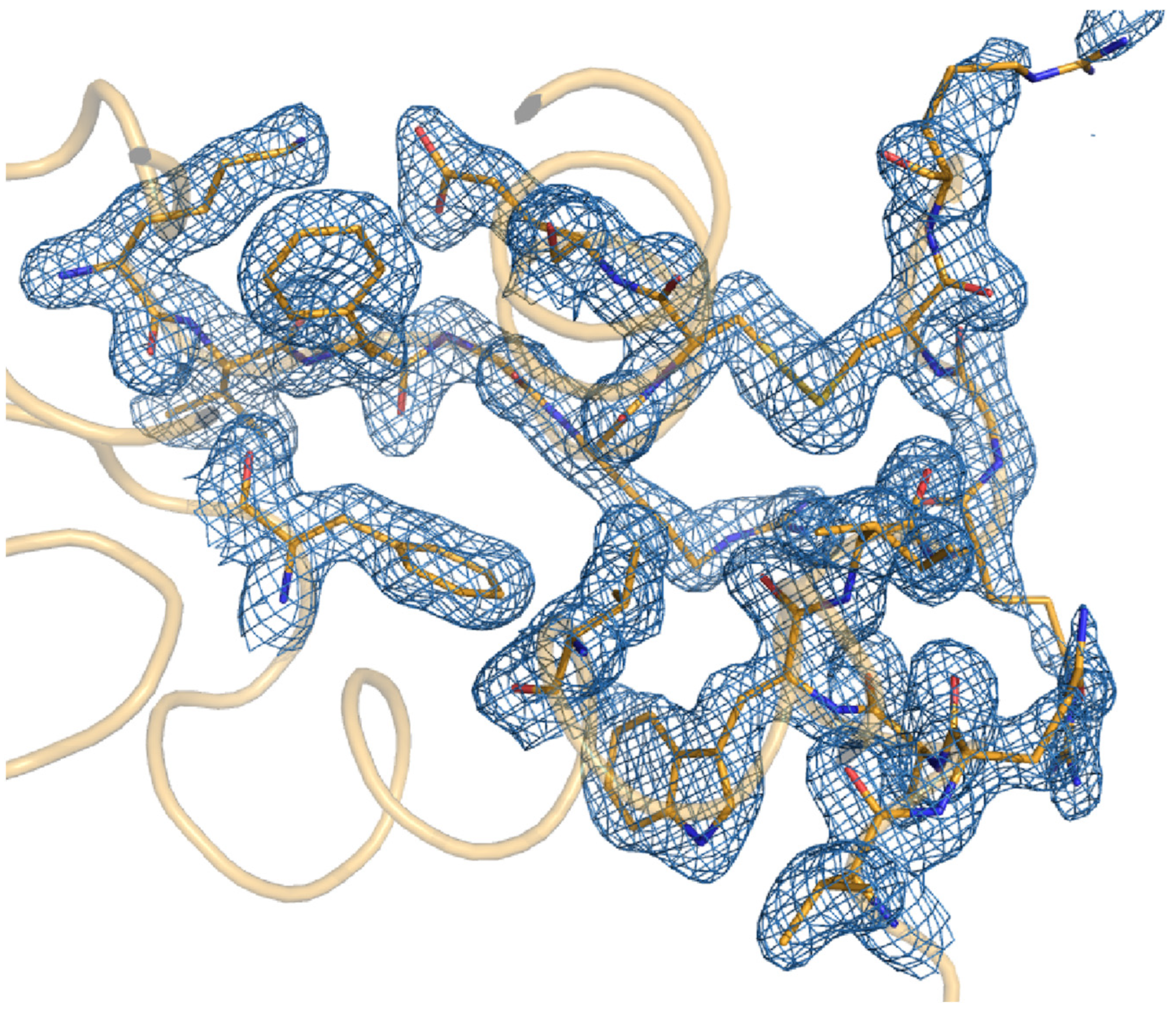
3.3. Structural Analysis of Lysozyme

We have used lysozyme microcrystals without an additional carrier matrix media to determine the room-temperature structure by the SFX experiment. The lysozyme microcrystals were formed by the batch method. Lysozyme powder (Cat No. L6876; Sigma Aldrich, Saint Louis, MO, USA) dissolved in buffer (0.1 M sodium acetate pH 4.0, 0.2 M NaCl) at a concentration of 100 mg/mL was mixed with an equivalent volume of crystallization buffer (0.1 M sodium acetate pH 4.0, 2 M NaCl, 5% PEG 6 K). The total number of collected images is 44,272, and the hitting ratio was about 49%. In addition, the frames of 42.2% out of the classified images were indexed, integrated, and merged in point group 4/mmm to a resolution cutoff of 1.8 Å with the CrystFEL suite (Ver. 0.9.1) [31,32,33,34]. Figures of merit were calculated using compare_hkl (Rsplit, CC1/2, and CC*) and check_hkl (SNR, redundancy, and completeness) software. The phase has been retrieved by the molecular replacement method with the Phenix [35], utilizing the lysozyme structure, which was previously deposited in the PDB (Protein Data Bank, PDB ID: 4ET8). Model building and structure refinement were performed with Coot (Crystallographic Object-Oriented Toolkit) [36,37]. The data collection and refinement statistics are given in Table 1. The electron-density map of lysozyme was very clear throughout the amino acid sequence from Lys19 to Leu147, except for the signal sequence from Met1 to Gly18, which was not included in the actual protein (Figure 3). The lysozyme structure determined by MRS showed high similarity with a previously deposited lysozyme structure (PDB ID: 4ET8) [2] with an RMS deviation of 0.121 Å for all C-α atoms. The electron-density map shows some additional density for water molecules. In the refined lysozyme structure, no signs of radiation damage were observed.

4. Discussion and Conclusions

A novel microcrystal delivery technique has been developed by employing a mini-rotor that winds the MCC according to the designated speed. Different from the previous setup serving real-time position feedback with a visual servo scheme, it does not require image processing during the scanning. This means that the applicable XFEL repetition rate can be increased by simply adjusting the rotational speed since there is no time lag for the image processing and position feedback.
For stable operation, the MCC should travel at a flat trajectory. To accomplish and maintain this motion control, proper tension and travel guides for the MCC should be adopted. In the aspect of the size of the instrument, however, compactness is one of the advantageous features regarding the instrumental handling and space constraints at the beamlines.
This simple structure of the tensioner and guides of the MRS system provides adequate tension for the stable operation of the reeling system. The applied pressure on the MCC during the operation can be estimated as a criterion for stable operation. The mini-rotor rotates a single turn with 2868 pulses provided by the motor controller. The time for a single turn of the mini-rotor is about 12.9 s. Then, it leads to a pulse rate of about 222 pps (pulses per second). Approximately, it corresponds to the torque value of about 70 gf ∙cm (in cgs unit) or 0.36 mN∙m (in MKS unit) (Figure S1). Since the radius of the rotor for reeling is 3.7 mm, the tangential force applied on the MCC for the corresponding torque is estimated as 97 mN. Considering the inner diameter and thickness of the MCC, the cross-sectional area to the length direction is about 4.08 × 103 μm2. Then, the applied pressure on the MCC is calculated as about 23.8 MPa. This value is below the yield strength of 13 μm thick polyimide material at 69 MPa [38]. It implies that the stable operation of the MRS works is feasible while making a flat traveling of the MCC. The stable operation of the MRS can also be observed from the movie taken with a long working distance microscope, which monitors the sample delivery during the experiment (Video S1).
The demonstration through the SFX experiment concludes that the MRS has the opportunity to overcome previous issues on the previously developed 1D fixed target based on the chip design. The operation is quite stable without any real-time position feedback to match the XFEL beam illumination position on the MCC. Since the MRS can omit the position calculation time of the MCC along with the operation, the applicable repetition rate of the XFEL source can be beyond the limited value given by the previous 1D fixed target [24]. However, more systematic studies on the specifications (length, strength, geometry of the components, etc.) of the microtubing should be performed to successfully apply the MRS to the XFEL sources operated in a MHz repetition rate.

Supplementary Materials

The following supporting information can be downloaded at https://www.mdpi.com/article/10.3390/photonics11010095/s1, Figure S1: The relation between the pps and the torque; Video S1: Operation of the MRS observed by the long-working distance microscope installed at the beamline.

Author Contributions

Conceptualization, J.K. and J.P.; methodology, S.P. and J.P.; formal analysis, J.K.; data curation, J.K., S.P. and J.P.; writing—original draft preparation, J.K. and J.P.; supervision, Y.C. and J.P.; funding acquisition, Y.C. and J.P. All authors have read and agreed to the published version of the manuscript.

Funding

This research was funded by the National Research Foundation of Korea, Grant No. NRF-2017M3A9F6029733 to J.P.

Institutional Review Board Statement

Not applicable.

Informed Consent Statement

Not applicable.

Data Availability Statement

The raw data supporting the conclusions of this article will be made available by the authors on request.

Acknowledgments

The experiments were performed using the SFX instrument at the PAL-XFEL funded by the Ministry of Science and ICT of Korea. The authors acknowledge the accelerator and beamline departments at the PAL-XFEL for their technical support.

Conflicts of Interest

The authors declare no conflicts of interest.

References

  1. Neutze, R.; Wouts, R.; van der Spoel, D.; Weckert, E.; Hajdu, J. Potential for biomolecular imaging with femtosecond X-ray pulses. Nature 2000, 406, 752–757. [Google Scholar] [CrossRef]
  2. Boutet, S.; Lomb, L.; Williams, G.J.; Barends, T.R.; Aquila, A.; Doak, R.B.; Weierstall, U.; DePonte, D.P.; Steinbrener, J.; Shoeman, R.L.; et al. High-resolution protein structure determination by serial femtosecond crystallography. Science 2012, 337, 362–364. [Google Scholar] [CrossRef]
  3. Chapman, H.N.; Fromme, P.; Barty, A.; White, T.A.; Kirian, R.A.; Aquila, A.; Hunter, M.S.; Schulz, J.; DePonte, D.P.; Weierstall, U.; et al. Femtosecond X-ray protein nanocrystallography. Nature 2011, 470, 73–77. [Google Scholar] [CrossRef]
  4. Liu, W.; Wacker, D.; Gati, C.; Han, G.W.; James, D.; Wang, D.; Nelson, G.; Weierstall, U.; Katritch, V.; Barty, A.; et al. Serial femtosecond crystallography of G protein-coupled receptors. Science 2013, 342, 1521–1524. [Google Scholar] [CrossRef]
  5. Spence, J.C.H.; Weierstall, U.; Chapman, H.N. X-ray lasers for structural and dynamic biology. Rep. Prog. Phys. 2012, 75, 102601. [Google Scholar] [CrossRef]
  6. DePonte, D.P.; Doak, R.B.; Hunter, M.; Liu, Z.; Weierstall, U.; Spence, J.C. SEM imaging of liquid jets. Micron 2009, 40, 507–509. [Google Scholar] [CrossRef]
  7. Deponte, D.P.; McKeown, J.T.; Weierstall, U.; Doak, R.B.; Spence, J.C. Towards ETEM serial crystallography: Electron diffraction from liquid jets. Ultramicroscopy 2011, 111, 824–827. [Google Scholar] [CrossRef]
  8. Weierstall, U.; James, D.; Wang, C.; White, T.A.; Wang, D.; Liu, W.; Spence, J.C.; Bruce Doak, R.; Nelson, G.; Fromme, P.; et al. Lipidic cubic phase injector facilitates membrane protein serial femtosecond crystallography. Nat. Commun. 2014, 5, 3309. [Google Scholar] [CrossRef]
  9. Sugahara, M.; Nakane, T.; Masuda, T.; Suzuki, M.; Inoue, S.; Song, C.; Tanaka, R.; Nakatsu, T.; Mizohata, E.; Yumoto, F.; et al. Hydroxyethyl cellulose matrix applied to serial crystallography. Sci. Rep. 2017, 7, 703. [Google Scholar] [CrossRef]
  10. Oghbaey, S.; Sarracini, A.; Ginn, H.M.; Pare-Labrosse, O.; Kuo, A.; Marx, A.; Epp, S.W.; Sherrell, D.A.; Eger, B.T.; Zhong, Y.; et al. Fixed target combined with spectral mapping: Approaching 100% hit rates for serial crystallography. Acta Crystallogr. D Struct. Biol. 2016, 72 Pt 8, 944–955. [Google Scholar] [CrossRef]
  11. Roedig, P.; Ginn, H.M.; Pakendorf, T.; Sutton, G.; Harlos, K.; Walter, T.S.; Meyer, J.; Fischer, P.; Duman, R.; Vartiainen, I.; et al. High-speed fixed-target serial virus crystallography. Nat. Methods 2017, 14, 805–810. [Google Scholar] [CrossRef]
  12. Sherrell, D.A.; Foster, A.J.; Hudson, L.; Nutter, B.; O’Hea, J.; Nelson, S.; Pare-Labrosse, O.; Oghbaey, S.; Miller, R.J.; Owen, R.L. A modular and compact portable mini-endstation for high-precision, high-speed fixed target serial crystallography at FEL and synchrotron sources. J. Synchrotron Radiat. 2015, 22, 1372–1378. [Google Scholar] [CrossRef] [PubMed]
  13. Doak, R.B.; Nass Kovacs, G.; Gorel, A.; Foucar, L.; Barends, T.R.M.; Grunbein, M.L.; Hilpert, M.; Kloos, M.; Roome, C.M.; Shoeman, R.L.; et al. Crystallography on a chip—without the chip: Sheet-on-sheet sandwich. Acta Crystallogr. D Struct. Biol. 2018, 74 Pt 10, 1000–1007. [Google Scholar] [CrossRef] [PubMed]
  14. Hunter, M.S.; Segelke, B.; Messerschmidt, M.; Williams, G.J.; Zatsepin, N.A.; Barty, A.; Benner, W.H.; Carlson, D.B.; Coleman, M.; Graf, A.; et al. Fixed-target protein serial microcrystallography with an x-ray free electron laser. Sci. Rep. 2014, 4, 6026. [Google Scholar] [CrossRef]
  15. Lee, D.; Baek, S.; Park, J.; Lee, K.; Kim, J.; Lee, S.J.; Chung, W.K.; Lee, J.L.; Cho, Y.; Nam, K.H. Nylon mesh-based sample holder for fixed-target serial femtosecond crystallography. Sci. Rep. 2019, 9, 6971. [Google Scholar] [CrossRef] [PubMed]
  16. Sierra, R.G.; Gati, C.; Laksmono, H.; Dao, E.H.; Gul, S.; Fuller, F.; Kern, J.; Chatterjee, R.; Ibrahim, M.; Brewster, A.S.; et al. Concentric-flow electrokinetic injector enables serial crystallography of ribosome and photosystem II. Nat. Methods 2016, 13, 59–62. [Google Scholar] [CrossRef]
  17. Fuller, F.D.; Gul, S.; Chatterjee, R.; Burgie, E.S.; Young, I.D.; Lebrette, H.; Srinivas, V.; Brewster, A.S.; Michels-Clark, T.; Clinger, J.A.; et al. Drop-on-demand sample delivery for studying biocatalysts in action at X-ray free-electron lasers. Nat. Methods 2017, 14, 443–449. [Google Scholar] [CrossRef]
  18. Zhao, F.Z.; Zhang, B.; Yan, E.K.; Sun, B.; Wang, Z.J.; He, J.H.; Yin, D.C. A guide to sample delivery systems for serial crystallography. FEBS J. 2019, 286, 4402–4417. [Google Scholar] [CrossRef]
  19. Sui, S.; Mulichak, A.; Kulathila, R.; McGee, J.; Filiatreault, D.; Saha, S.; Cohen, A.; Song, J.; Hung, H.; Selway, J.; et al. A capillary-based microfluidic device enables primary high-throughput room-temperature crystallographic screening. J. Appl. Crystallogr. 2021, 54 Pt 4, 1034–1046. [Google Scholar] [CrossRef]
  20. Nogly, P.; James, D.; Wang, D.; White, T.A.; Zatsepin, N.; Shilova, A.; Nelson, G.; Liu, H.; Johansson, L.; Heymann, M.; et al. Lipidic cubic phase serial millisecond crystallography using synchrotron radiation. IUCrJ 2015, 2 Pt 2, 168–176. [Google Scholar] [CrossRef]
  21. Botha, S.; Nass, K.; Barends, T.R.M.; Kabsch, W.; Latz, B.; Dworkowski, F.; Foucar, L.; Panepucci, E.; Wang, M.T.; Shoeman, R.L.; et al. Room-temperature serial crystallography at synchrotron X-ray sources using slowly flowing free-standing high-viscosity microstreams. Acta Crystallogr. D 2015, 71, 387–397. [Google Scholar] [CrossRef] [PubMed]
  22. Beyerlein, K.R.; Dierksmeyer, D.; Mariani, V.; Kuhn, M.; Sarrou, I.; Ottaviano, A.; Awel, S.; Knoska, J.; Fuglerud, S.; Jonsson, O.; et al. Mix-and-diffuse serial synchrotron crystallography. IUCrJ 2017, 4 Pt 6, 769–777. [Google Scholar] [CrossRef] [PubMed]
  23. Zielinski, K.A.; Prester, A.; Andaleeb, H.; Bui, S.; Yefanov, O.; Catapano, L.; Henkel, A.; Wiedorn, M.O.; Lorbeer, O.; Crosas, E.; et al. Rapid and efficient room-temperature serial synchrotron crystallography using the CFEL TapeDrive. IUCrJ 2022, 9 Pt 6, 778–791. [Google Scholar] [CrossRef] [PubMed]
  24. Lee, D.; Park, S.; Lee, K.; Kim, J.; Park, G.; Nam, K.H.; Baek, S.; Chung, W.K.; Lee, J.L.; Cho, Y.; et al. Application of a high-throughput microcrystal delivery system to serial femtosecond crystallography. J. Appl. Crystallogr. 2020, 53 Pt 2, 477–485. [Google Scholar] [CrossRef] [PubMed]
  25. Liu, Z. Dynamic analysis of center-driven web winder controls. In Conference Record of the 1999 IEEE Industry Applications Conference. In Proceedings of the Thirty-Forth IAS Annual Meeting (Cat. No.99CH36370), Phoenix, AZ, USA, 3–7 October 1999; pp. 1388–1396. [Google Scholar]
  26. Park, J.; Kim, S.; Nam, K.H.; Kim, B.; Ko, I.S. Current status of the CXI beamline at the PAL-XFEL. J. Korean Phys. Soc. 2016, 69, 1089–1093. [Google Scholar] [CrossRef]
  27. Kang, H.S.; Min, C.K.; Heo, H.; Kim, C.; Yang, H.; Kim, G.; Nam, I.; Baek, S.Y.; Choi, H.J.; Mun, G.; et al. Hard X-ray free-electron laser with femtosecond-scale timing jitter. Nat. Photonics 2017, 11, 708. [Google Scholar] [CrossRef]
  28. Ko, I.S.; Kang, H.S.; Heo, H.; Kim, C.; Kim, G.; Min, C.K.; Yang, H.; Baek, S.Y.; Choi, H.J.; Mun, G.; et al. Construction and Commissioning of PAL-XFEL Facility. Appl. Sci 2017, 7, 479. [Google Scholar] [CrossRef]
  29. Kim, J.; Kim, H.Y.; Park, J.; Kim, S.; Kim, S.; Rah, S.; Lim, J.; Nam, K.H. Focusing X-ray free-electron laser pulses using Kirkpatrick-Baez mirrors at the NCI hutch of the PAL-XFEL. J. Synchrotron Radiat. 2018, 25, 289–292. [Google Scholar] [CrossRef]
  30. Park, J.; Kim, S.; Kim, S.; Nam, K.H. Multifarious injection chamber for molecular structure study (MICOSS) system: Development and application for serial femtosecond crystallography at Pohang Accelerator Laboratory X-ray Free-Electron Laser. J. Synchrotron Radiat. 2018, 25, 323–328. [Google Scholar] [CrossRef]
  31. White, T.A. Post-refinement method for snapshot serial crystallography. Philos. Trans. R Soc. B 2014, 369, 20130330. [Google Scholar] [CrossRef]
  32. White, T.A.; Barty, A.; Liu, W.; Ishchenko, A.; Zhang, H.T.; Gati, C.; Zatsepin, N.A.; Basu, S.; Oberthür, D.; Metz, M.; et al. Serial femto-second crystallography datasets from G protein-coupled receptors. Sci. Data 2016, 3, 160057. [Google Scholar] [CrossRef] [PubMed]
  33. White, T.A.; Barty, A.; Stellato, F.; Holton, J.M.; Kirian, R.A.; Zatsepin, N.A.; Chapman, H.N. Crystallographic data processing for free-electron laser sources. Acta Crystallogr. D 2013, 69, 1231–1240. [Google Scholar] [CrossRef] [PubMed]
  34. White, T.A.; Kirian, R.A.; Martin, A.V.; Aquila, A.; Nass, K.; Barty, A.; Chapman, H.N. CrystFEL: A software suite for snapshot serial crystallography. J. Appl. Crystallogr. 2012, 45, 335–341. [Google Scholar] [CrossRef]
  35. Liebschner, D.; Afonine, P.V.; Baker, M.L.; Bunkóczi, G.; Chen, V.B.; Croll, T.I.; Hintze, B.; Hung, L.W.; Jain, S.; McCoy, A.J.; et al. Macromolecular structure determination using X-rays, neutrons and electrons: Recent developments in Phenix. Acta Crystallogr. D 2019, 75, 861–877. [Google Scholar] [CrossRef]
  36. Emsley, P.; Lohkamp, B.; Scott, W.G.; Cowtan, K. Features and development of Coot. Acta Crystallogr. D Biol. Crystallogr. 2010, 66, 486–501. [Google Scholar] [CrossRef]
  37. Available online: http://www2.mrc-lmb.cam.ac.uk/personal/pemsley/coot/ (accessed on 13 December 2023).
  38. Available online: https://www.matweb.com/search/datasheet.aspx?matguid=99c680bc28dd409fb7e8fd3ddbcee537 (accessed on 7 September 2023).
Figure 1. (a) Geometry of micro-tubing reeling system; (b) guiding tubes to maintain trajectory of the MCC; and (c) holes generated by XFEL pulses on the MCC (white bar = 50 μm).
Photonics 11 00095 g001
Figure 2. (a) Photo of the MRS unit; (b) installation image of the MRS unit in the MICOSS at the NCI endstation of the PAL-XFEL.
Photonics 11 00095 g002
Figure 3. The 2Fo-Fc electron-density map of lysozyme defined by the MRS at 293 K. The 2Fo-Fc electron-density map (blue mesh, 1σ) is shown with the surface region of hen egg-white lysozyme (orange).
Photonics 11 00095 g003
Table 1. Data collection and refinement statistics.
Data CollectionLysozyme
PDB code8JQV
Wavelength (Å)1 Å
Exposure time25 fs
Space groupP 43 21 1
Cell dimensions
a,b,c (Å)79.3, 79.3, 38.3
α, β, γ (°)90.0, 90.0, 90.0
No. of collected images44,272
No. of hit images21,633
No. of indexed images9132
Resolution (Å)50–1.80 (1.87–1.80) a
No. of unique reflections12,462 (1224)
Completeness (%)100 (100)
Redundancy335.6 (233.8)
SNR3.62 (1.36)
Rsplit b25.98 (78.87)
CC1/20.91 (0.42)
CC* c0.98 (0.77)
Wilson B-factor (Å2)32.17
Refinement statistics
Resolution (Å)39.65–1.80 (1.94–1.80)
R-work0.2040 (0.3772)
R-free c0.2302 (0.3911)
RMS deviations
Bond (Å)0.006
Angle (°)0.879
Average B-factor (Å2)
Protein29.07
Water35.78
Clash score3.06
Ramachandran (%)
Favored97.64
Allowed2.36
Rotamer outlier (%)0.00
a The values in parentheses are for the highest-resolution shell. b Rsplit =  1 2 · h k l I h k l e v e n I h k l o d d 1 2 I h k l e v e n I h k l o d d . c The free set represents a random 5% of reflections not included in refinement. c cc* = 2 C C 1 / 2 1 + C C 1 / 2
Disclaimer/Publisher’s Note: The statements, opinions and data contained in all publications are solely those of the individual author(s) and contributor(s) and not of MDPI and/or the editor(s). MDPI and/or the editor(s) disclaim responsibility for any injury to people or property resulting from any ideas, methods, instructions or products referred to in the content.

