Review

The Arago–Poisson Spot: New Applications for an Old Concept

1
Univ Rennes, F-35000 Rennes, France
2
Univ Rennes, CNRS, IPR-UMR 6251, F-35000 Rennes, France
*
Author to whom correspondence should be addressed.
These authors contributed equally to this work.
Photonics 2024, 11(1), 55; https://doi.org/10.3390/photonics11010055
Submission received: 6 December 2023 / Revised: 27 December 2023 / Accepted: 29 December 2023 / Published: 4 January 2024
(This article belongs to the Special Issue Advancements in Optical Beam Design and Applications)

Abstract

:
Herein, we report some specific properties and applications of the so-called Arago–Poisson spot in optics. This spot results from the diffraction of a plane wave by an occulting disk that leads to a small bright spot in its shadow. We discuss some of the properties of such beams. In particular, we focus on the ultimate size that can be reached for these beams, which depends on the diameter of the disk, the wavelength, and the distance from the disk. We also highlight self-healing and faster-than-light properties. Applications are then proposed. The applications mainly deal with new traps with nanometer sizes dedicated to the trapping of nanoparticles. We also discuss beams that change frequency during propagation and their application for signal delivery in a precise and determined area.

1. Introduction

From an historical point of view, the so-called Arago–Poisson spot has played a major role in the demonstration of light’s wave nature [1,2,3,4]. In 1819, in response to a contest sponsored by the Académie des Sciences in France, Fresnel presented a manuscript based on light’s wave nature. Poisson, a fervent supporter of a corpuscular model—in order to discredit Fresnel’s theory—discovered a surprising consequence of Fresnel’s equations: if a light source is placed on the axis of a circular obstacle that blocks the light, Fresnel’s theory predicts that there will be a bright spot behind the screen, whereas Poisson supposed, by using common sense, that the spot should be dark. Arago actually conducted the experiment and a bright spot was indeed observed. This was then named after Arago and Poisson. Sometimes only the name of Arago or the name of Poisson is associated with the phenomenon, and the name of Fresnel is also associated with them in other cases. Later, this was recognized to be responsible for damages in unstable cavities [5]. It has also been shown to propagate faster than light [6,7,8,9]. Usually, it propagates in a quasi non-diffracting way [10], and its size should decrease when it moves closer to the disk [11]. The appearance of the spot is not limited to optics and has also been observed for X-rays [12], in acoustics [13], for gravitational waves [14], and even with particles such as molecules [15,16].
Beyond these properties, the aim of this paper is to review some of its most important properties, emphasizing the ultimate size of the spot that has rarely been previously addressed and to investigate the practical applications of the Arago–Poisson spots in optics and in domains such as astronomy, lithography, or alignment. The article will focus on colloidal trapping and signal delivery. The article is organized as follows. The next paragraph (Section 2) recalls several theoretical concepts (Section 2.1). The following paragraphs then deal with experimental considerations (Section 2.2) and some elementary properties (Section 2.3), especially the spot’s ultimate size (Section 2.3.1). Then, Section 3 includes a detailed discussion of various applications, such as particle trapping (Section 3.1) and changing frequency beams (Section 3.2) before the article reaches a conclusion in Section 4.

2. Results

2.1. Theoretical Considerations

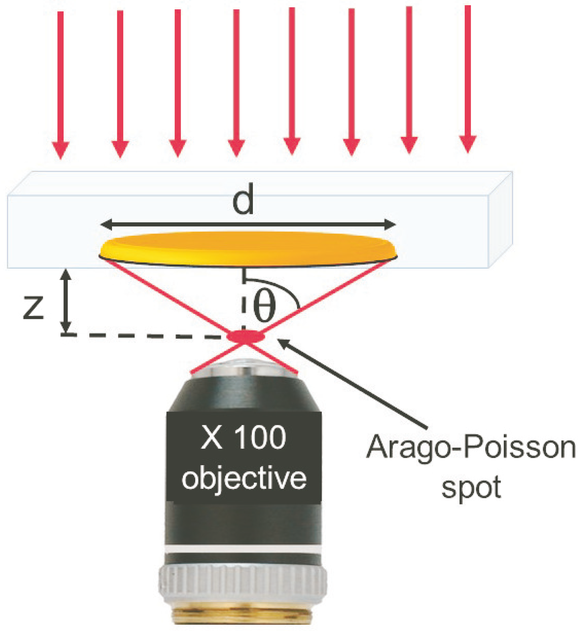
Let us consider a plane wave impinging on an absorbing occulting disk (diameter d) centered on the beam axis (see Figure 1a). A bright Arago–Poisson spot appears in the shadow of the disk (see Figure 1b). When one considers the rays diffracted by the disk at a distance z from the disk, these rays interfere constructively on-axis and destructively off-axis. The intensity distribution can be calculated using the Huygens–Fresnel principle [17]. It states that every unobstructed point of the plane wavefront becomes the source of a secondary spherical wavelet. The amplitude of the optical field at a given point is the superposition of all the secondary wavelets with their relative phases. This can be solved numerically [18]. However, the radial intensity distribution I ( r ) at a distance z from the occulting disk can be approximated analytically, in the near field diffraction regime, by a squared zeroth Bessel function J 0 [19].
I ( r ) I 0 z 2 z 2 + ( d / 2 ) 2 J 0 2 π r λ d z 2 + ( d / 2 ) 2 1 / 2
where I 0 is the intensity of the incoming plane wave, and λ its wavelength. As z tends to zero, the Bessel function equals J 0 2 ( 2 π r / λ ) . It does not depend on the disk’s diameter any more. However, the intensity of the spot decreases to zero. On the other hand, far from the disk, Equation (1) reduces to the usual formula [2,3,20],
I ( r ) I 0 z 2 z 2 + ( d / 2 ) 2 J 0 2 π r d λ z I 0 J 0 2 π r d λ z
The intensity of the Arago–Poisson spot is indeed the same as the intensity of the incoming beam.
It has been shown [21,22] that light diffraction from an occulting disk could lead to a dark Arago–Poisson spot instead of a bright one. For this to occur, the usual plane wave has to be replaced by a vortex beam [23,24,25]. Briefly, such vortex beams carry Orbital Angular Momentum (OAM) and have a non-uniform phase distribution. On a plane perpendicular to the direction of propagation, the phase varies uniformly from 0 to 2 π . is an integer that is usually called the topological charge of the beam. Diffracted by a disk centered on the beam axis, the spot retains its topological charge. Its intensity distribution is then described by the square of the th Bessel function J . It varies as
I ( r ) I 0 z 2 z 2 + ( d / 2 ) 2 J 2 π r λ d z 2 + ( d / 2 ) 2 1 / 2
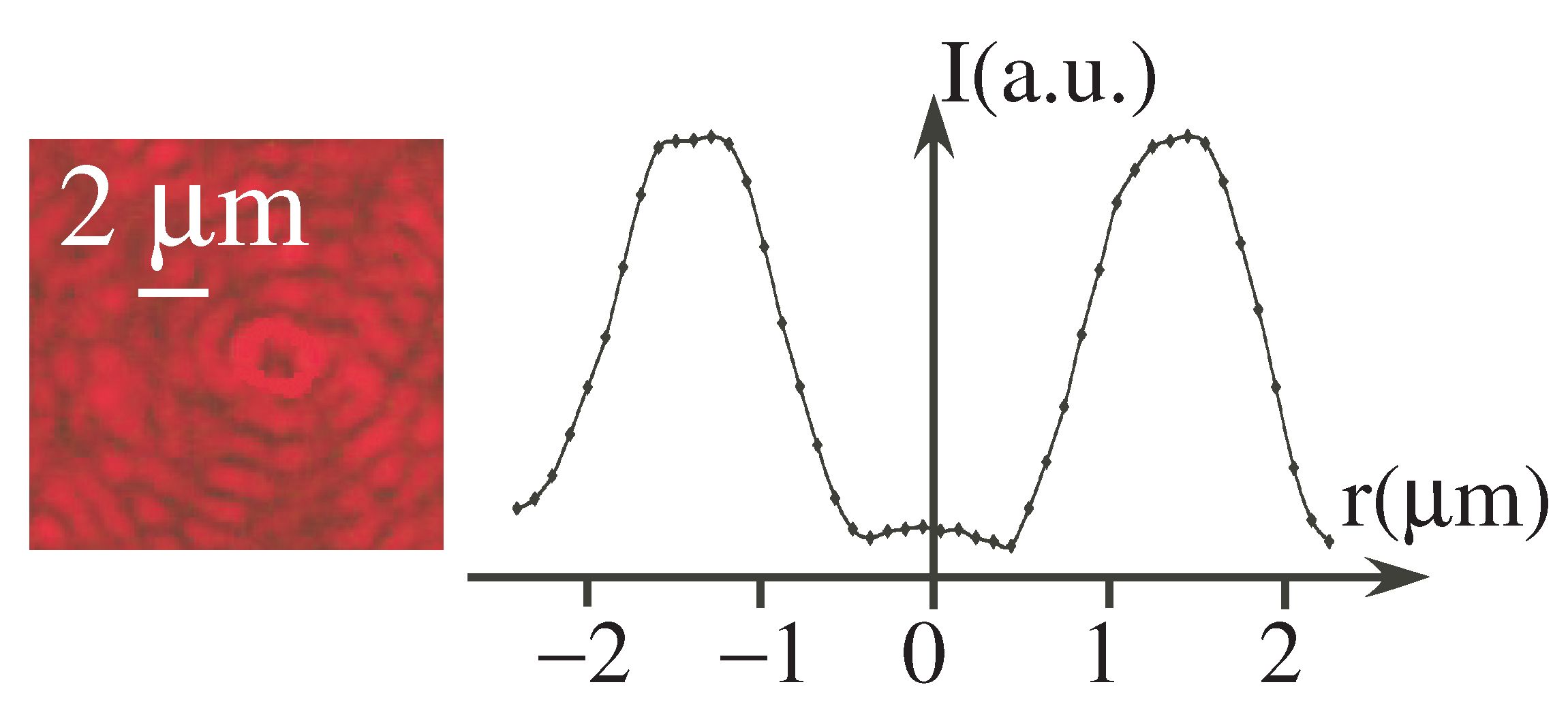
As for the Equation (2), far from the disk, the J function could be approximated by J 2 π r d / ( λ z ) [21,22,26]. Figure 2 shows an example of the intensity distribution for = 4 , z = 400 μ m and for a disk diameter of d = 600 μ m.

2.2. Experiments

In order to investigate the properties of the Arago–Poisson spot, the following set-up was used (see Figure 3). It was previously described in [27]. Briefly, a collimated laser beam with several possible wavelengths ( λ = 636, 561, 532, 488 and 404 nm, Oxyus lasers L6Cc) impinges on a dark absorbing object. An aspheric collimator lens (Thorlabs CFC-2X-A) adjusts the size of the laser beam to the size of the disk. The dark absorbing disks (diameter d = 500 to 900 μ m) are made of chromium, deposited on a 2 mm thick BK7 glass. Special care is taken to align the axis of the beam with the axes of the disk and the microscope. The deposited side of the chromium points towards the objective of the microscope (and not towards the laser), so that the Arago–Poisson spot travels only in the air.
The diffracted light interferes in a bright spot in the centre of the disk shadow. It propagates and it is imaged with an inverted microscope (Leica DMi8) with a ×100 objective (Numerical Aperture NA = 0.95 in air). This numerical aperture is defined by n sin θ , n being the index in the medium we look at (air in our case), and θ being the maximal angle of incidence. Light rays diffracted by the edges of the disk, impinge with an angle θ with respect to the vertical axis. It equals θ = tan 1 ( d / 2 z ) at the spot location (see Figure 1a). This therefore means that we cannot observe a spot at a distance shorter than 100 μ m for a d = 600 μ m disk.
The disk position can be adjusted using servo-controlled micro-stages positioners in the XYZ directions, with sub-micrometer resolution. The position z = 0 corresponds to the focus of the microscope on the chromium-deposited dark disk. The camera is a Hamamatsu monochrome gray-scale CCD camera (C11440). We have calibrated the imaging system against a test pattern. One pixel corresponds to 60 nm.
The size of the spot is not limited by diffraction. This spot could be smaller than the wavelength and may exceed the resolving power or the Rayleigh criterion of a usual microscope. In fact, this criterion tells us that a faithful image requires that all the spectra contribute to the formation of the image [2]. This is never possible using ordinary lenses. Several proposals have been made to go beyond the diffraction limited focusing size of the spot. Some used the (usually lost) near field components of light to make a sub wavelength spot in the near field [28,29], or collect it via masks to achieve super-resolution [30]. Others proposed designing a mask or a polarization distribution that corresponds to a sub-wavelength image after propagation [31,32]. It is very similar, in its principle, to negative refraction, which has the power to focus all Fourier components of a 2D image, thus creating a perfect lens [33] and also beating the Rayleigh criterion.
It is worth noting that, in the case of the Arago–Poisson spot, it is a little different, since the sub-wavelength spot propagates over millimeter/centimeter distances. Indeed, all the spectra components are within a cone, which angle equals θ . The azimuthal superposition of these waves leads to the Arago–Poisson spot. As soon as the numerical aperture of the microscope is higher than this angle, all components enter the microscope. There is no component left. It could then be that the image reaches hundred of nanometer sizes, well below λ .

2.3. Properties

Let us investigate some of the main properties of the Arago–Poisson spot.

2.3.1. Ultimate Arago–Poisson Beam Size

As the distance from the occulting disk decreases, the spot size also decreases. However, according to Equation (1), the intensity distribution tends towards
I ( r ) I 0 z 2 ( d / 2 ) 2 J 0 2 2 π r λ
While the intensity becomes smaller, the beam size tends toward a finite value. Yet, since the intensity distribution is not Gaussian, it is necessary to define how to determine the beam size. We nevertheless decided to characterize the spot by a “waist”, as for Gaussian beams [5]. It is defined as the distance from the spot axis at which the irradiance has fallen to 1 / e 2 of its maximum value. It is, therefore, also the value at which the zeroth-order Bessel function has fallen to 1 / e 2 of its maximum value. It corresponds to the value of the square of the Bessel function with the argument equal to 1.75. According to this definition, the ultimate spot size is thus
2 π r m i n λ = 1.75 r m i n = 1.75 λ 2 π
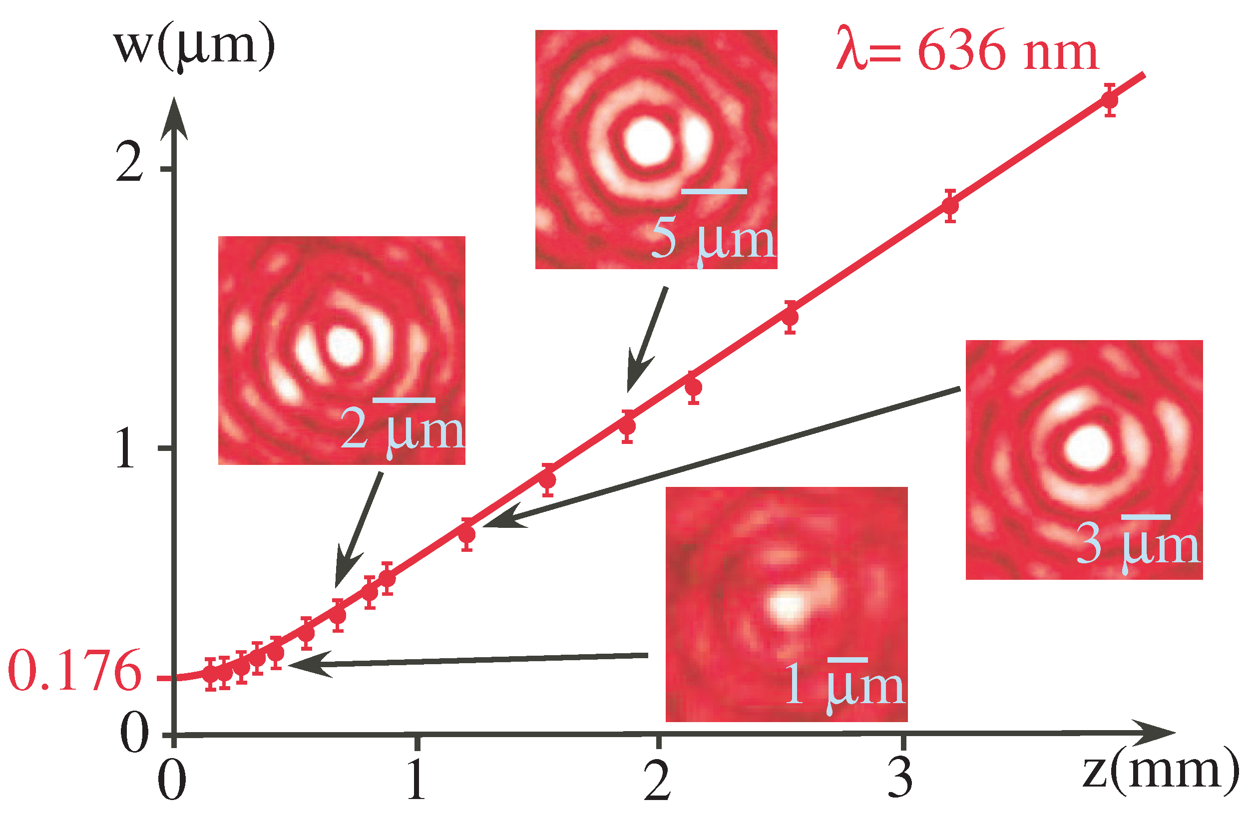
It exceeds the Abbe diffraction limited ultimate size of a Gaussian beam which is defined as w = 0.5 λ / NA l [34], where NA l is the numerical aperture of the focusing lens. However, for a given wavelength regardless of the diameter of the disk, the value found in Equation (5) is a finite value. For example, for λ = 633 nm, the ultimate spot size equals w m i n = 176 nm. This is confirmed by the experimental study of the Arago–Poisson beam size as a function of the distance from the occulting disk of Figure 4.
However, according to Equation (4), there is another way to decrease the ultimate spot size. This can be achieved by decreasing the wavelength λ . Actually, the spot size varies linearly with wavelength, according to Equation (1). This can be easily verified experimentally, as can be seen in Figure 5. The agreement between the experimental values and the theoretical curve is very good. Nevertheless, decreasing the wavelength down the ultraviolet or X-rays domain may not be practical.
On the other hand, for a given distance, and not too close to the occulting disk, redwe can reduce the spot size by increasing the occulting disk diameter d. Actually, as for the wavelength, the spot size varies linearly with the occulting disk diameter, according to Equation (1). This is shown in Figure 6. The agreement between the experimental curve and the theoretical one is very good.
Nevertheless, it should once again be noted that the ultimate spot size does not depend on the diameter of the occulting since, according to Equation (4), the argument of the Bessel function does not depend on d. Additionally, reducing spot size always comes at the cost of lower beam intensity. In order to enhance the light intensity, it has been shown that using an annular beam with a diameter of the order of the diffracting disk could be an interesting solution [35].
The properties that have been described so far are also valid for the dark spots of Arago–Poisson, which carries OAM (see Section 2.1). This could have interesting applications in atom optics in the realization of atom guides and atomic funnels [36,37], since OAM beams are sometimes difficult to focus due to other modes that may be present in the beam. Besides, focused OAM beams diverge rapidly [25], which is not the case for Arago–Poisson OAM beams (see following Section 2.3.2).
Arago–Poisson spots have also been produced with molecules [15,16]. A 1 μ m spot has been obtained with helium molecules. It has been proposed to be used for molecular microscopy. There are two main advantages of this. The first is that contrary to electron microscopy, helium is neutral. It does not damage the material studied. The second one is that the de Broglie wavelength could be very small (0.06 nm for a thermal beam), in the same wavelength range as X-ray wavelengths. However, unlike X-rays, helium molecules are totally safe for biological uses, for example.

2.3.2. Self-Healing and Nondiffractive Properties

As can be seen in Equation (1), the Arago–Poisson spot is expressed using a Bessel function of the first kind. In this respect, it resembles Bessel beams [38,39]. A true Bessel beam is nondiffractive. This means that as it propagates, it does not diffract and spread out [40,41,42]. It maintains its intensity over a limited spatial range. It can be generated by an axicon lens [43,44,45], sometimes combined with binary amplitude filters [45,46], or using gratings [47]. It can be used, for example, in microscopy [48,49], in biology [50], in medicine [51], or even in ophtalmhology [52].
However, the Arago–Poisson spot is not, strictly speaking, a nondiffracting beam. According to Equation (3), it diverges slightly along propagation with an angle
α = 1.75 λ π d
This can be verified on Figure 4. However, this variation must compared with the divergence of a usual Gaussian [5]
β = λ π w 0
w 0 is the ’true’ beam waist of the Gaussian beam. The ratio between the two is α / β = 1.75 w 0 / d . For a strongly focused Gaussian beam ( w 0 = 1.0 μ m), compared with an Arago–Poisson spot ( d = 0.6 mm, as in our experiment), it leads to α / β = 3 × 10 3 , i.e., the divergence of a Gaussian beam is more than two orders of magnitude higher than the divergence of an Arago–Poisson spot. Besides, the higher the diameter of the occulting beam, the smaller the divergence. However, while the Bessel beams that have been generated up to now exhibit non-diffracting properties over a limited distance, the Arago–Poisson spot retains its properties over the entire propagation distance. In addition, its generation is much less expensive, since only an occulting disk is needed.
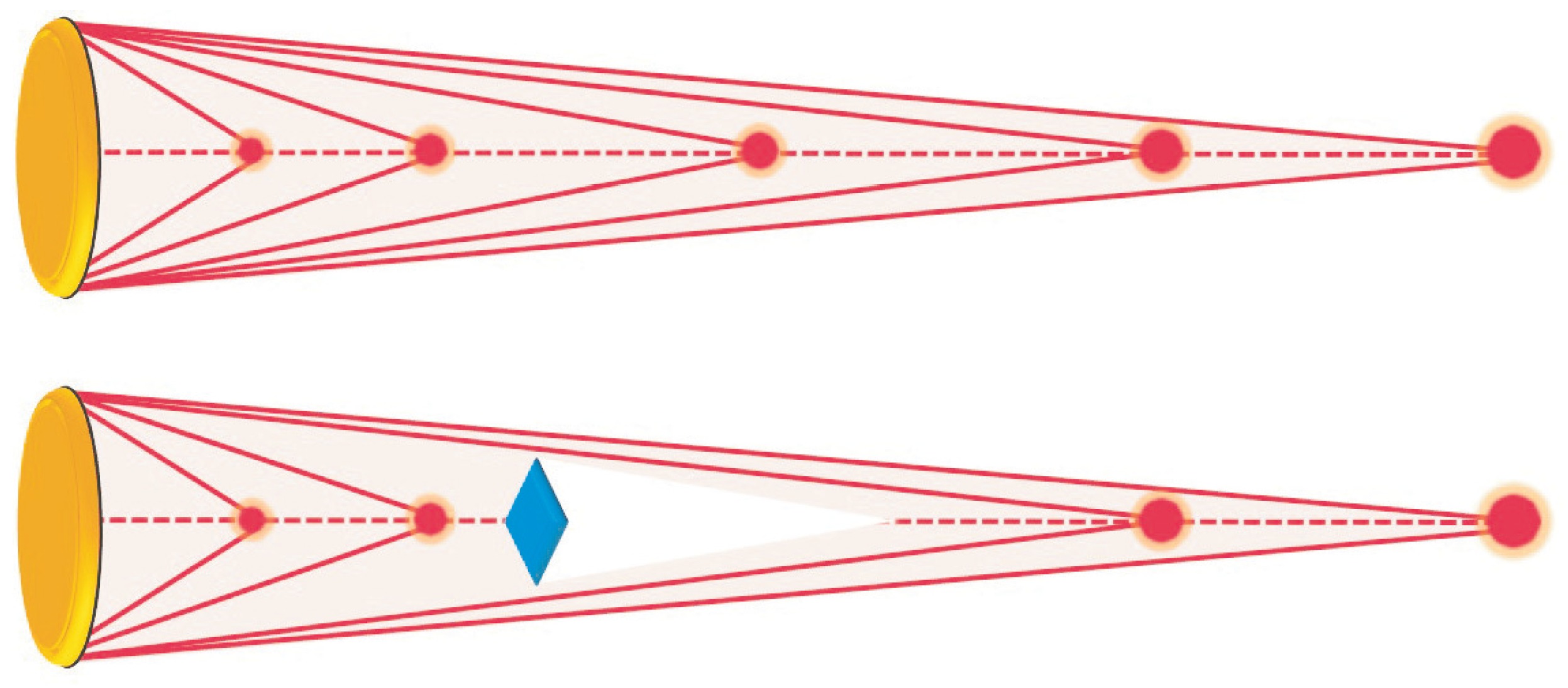
As for Bessel beams, since it is expressed with the Bessel function, the Arago–Poisson spot has self-healing properties. A self-healing beam has the ability to reconstruct itself after hitting an obstacle [38,48,53,54,55,56]. The principle of self-healing of the Arago–Poisson spot is explained in Figure 7. When an object is inserted in the propagation of an Arago–Poisson spot, the rays forming the spot close to the object are absorbed. There is no longer a spot in the vicinity of the perturbing object. However, the rays forming the spot at a longer distance are not perturbed. The spot is still present far from the object. This is also true for the dark spots of Arago–Poisson with beams carrying OAM [57]. However, the Arago–Poisson spots are not resilient to atmospheric turbulences [58].

2.3.3. Faster-Than-Light Properties

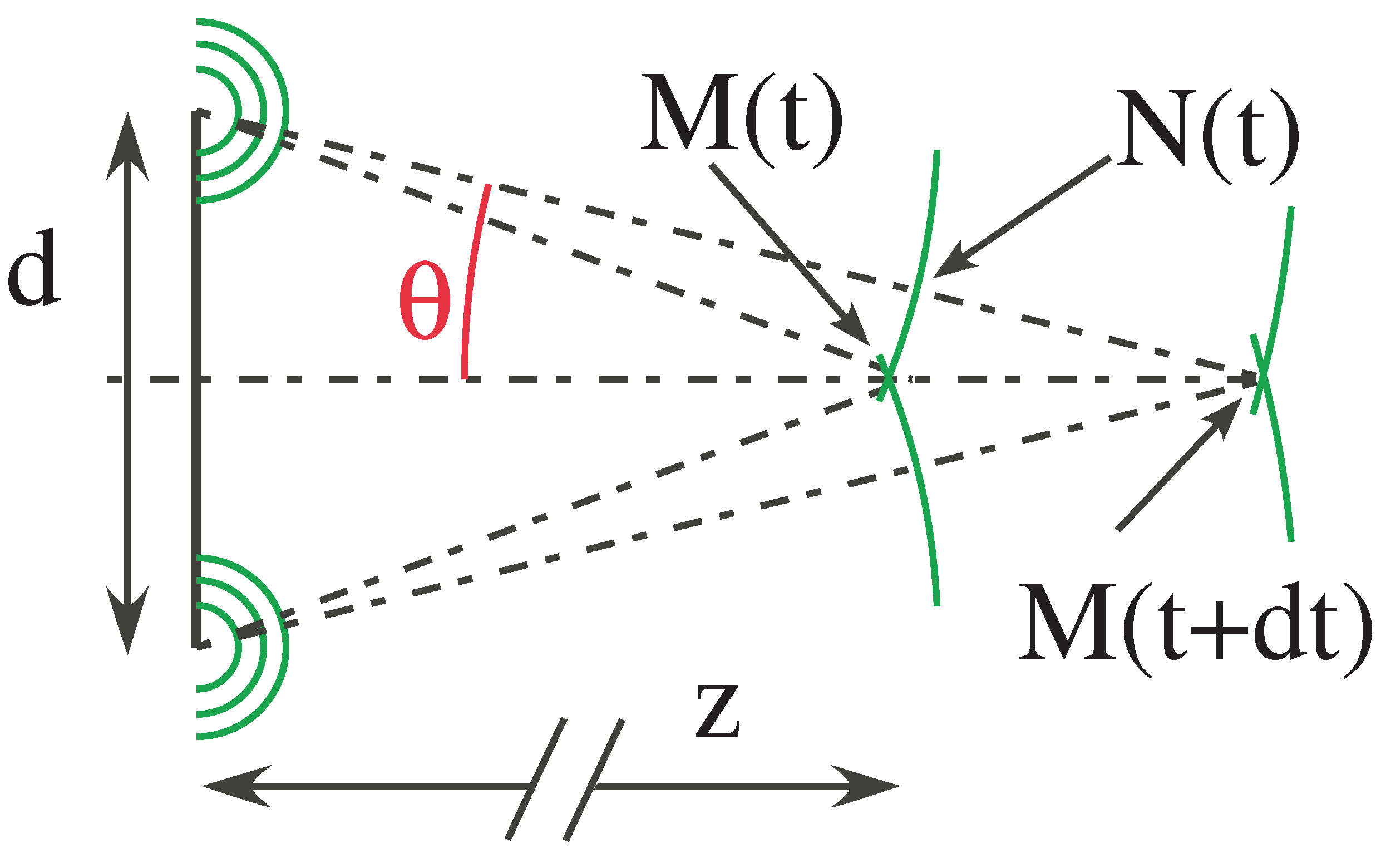
The Arago–Poisson spot has been shown to have faster-than-light properties [6,7]. This can be understood in the following way. Let us consider diffraction by an occulting disk as the one depicted in Figure 8, and let us consider a spherical wavelet originating from the edges of the disk. At time t, the wavelet passes through point M ( t ) and N ( t ) , and through M ( t + d t ) later at time ( t + d t ) . Since light travels at velocity c (we assume here that it is in a vacuum without loss of generality), during the time interval d t , it has traveled a distance c d t , from N ( t ) to M ( t + d t ) . However, on the axis, the spot has traveled from M ( t ) to M ( t + d t ) . Such a distance equals the distance from N ( t ) to M ( t + d t ) divided by cos θ . The apparent velocity is therefore
v = c cos θ = c z 2 + d 2 z 2
It is clearly faster than light. The closer to the occulting disk, the faster than light [6,7,8,9]. This superluminal behavior is actually due to the fact that the Arago–Poisson spot is an interference effect. It could be considered as an azimuthal superposition of plane waves of equal inclination with respect to the optical axis. Then, as for scissor blades, their contact point can move faster than light [59,60]. However, as for Airy beams [40,61], this superluminal interference effect obviously does not violate causality and cannot propagate information at a speed higher than c, because no photon propagates along the axis at the speed given by Equation (8).

3. Discussion

Several applications of the Arago–Poisson spot have already been considered. Since the spots are very tiny, they can be used in litography [62,63], to print sub-micrometer circuits. They could also be used in alignment [64,65,66,67], or to study aberrations [68]. Still considering the Arago–Poisson spot in optics, it has been used to measure velocities in fluids [69]. With X-rays [12], in a way analogous to the Arago–Poisson spot, the Bragg diffraction peaks interfere constructively or destructively on the axis, in the shadow of the sample to be studied. Then, instead of performing a 2D mapping to identify the different diffraction peaks, it has been shown that it could be replaced by a 1D mapping in the z direction. In acoustics [13], this enables to identify localization or mislocalization sources by listeners.
There have also been some interesting applications in astronomy. An Arago–Poisson spot can appear in the blurry image of a star given by a defocused Newton telescope. In this case, the star constitutes an ideal point source at infinity, and the secondary mirror of the telescope constitutes the circular obstacle [70]. It can also appear in coronagraphs [71,72,73]. A coronagraph is a disk attached to a telescope designed to block out the direct light from a star or another bright object so that nearby objects—which otherwise would be hidden in the object’s bright glare—can be resolved. To circumvent this effect, an occluder with petals, otherwise known as a starshade, has been proposed [74,75]. It is specifically designed to avoid diffraction on the central axis.
On the contrary, in astronomy, the Arago–Poisson spot could contribute to increasing the resolution of telescopes. The idea is to place a suitable disk in space accompanied by a separate telescope some distance away along its axis [76,77]. The resolution of the system would be equal to the resolution of a conventional lens with the same size of the occluder. As such, 100 m diameter occluders made of light weight plastic can be considered; these would lead to better resolution than that of the Hubble Space Telescope [78,79] with a much lower cost. However, the light intensity would be much lower.
In the following section, two applications of the Arago–Poisson spot in optics in different domains will be considered. The first will discuss nanoparticle trapping, while the second will deal with communication addressing.

3.1. Particle Trapping

Since the first report by [80] in 1986, optical tweezers have become a powerful tool for manipulating and trapping micrometer to nanometer particles [81,82,83,84]. They are trapped at the focal point of a tightly focused beam. The mechanism relies on optical gradient forces. However, due to light diffraction, optical tweezer trap sizes are limited to a fraction of a micrometer [81]. Besides, the force involved further decreases to the power of three of the particle diameter [85], thus limiting their applications for nanometer–sized particles.
In order to circumvent these limitations, two different main directions have been followed. The first combines tight light focusing and total internal reflection [86,87,88]. However, although the size of the trapis in the nanometer range is perpendicular to the interface, it is still limited by diffraction in the other directions. The other uses a plasmon-enhanced electromagnetic field to break the diffraction limit [89,90,91,92,93,94]. Nevertheless, these nanometric optical tweezers are based on dedicated plasmonic structures. One is still looking for versatile nanometer size optical traps.
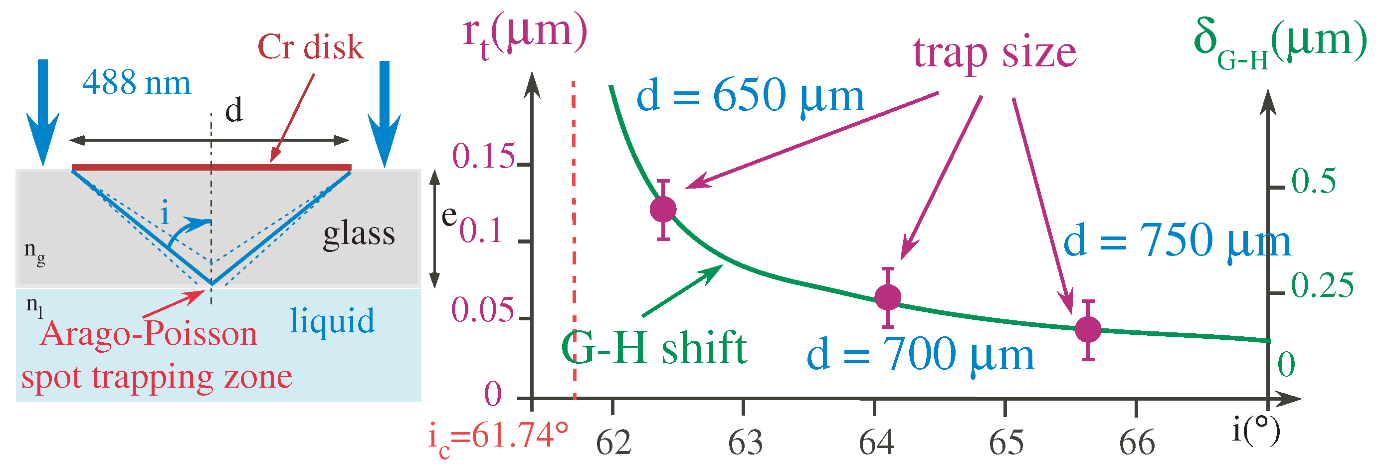
The Arago–Poisson spot can reach sub-micrometer dimensions (see Section 2.3.1) and could be a good candidate towards nanometer scale traps. However, since the spot is diffraction free, it retains its characteristics throughout propagation and cannot efficiently trap in this direction. Additionally, the intensity is rather low. In order to get around these problems, we therefore proposed the following experimental set-up (see Figure 9) [27,95]. The blue light from a laser ( λ = 488 nm) impinges on a glass lamella ( e = 170 μ m) with an occulting disk deposited on the top of the glass (i.e., oriented towards the laser), leading to an Arago–Poisson spot that propagates through the glass and then into a colloid suspension in demineralized water (see [95] for more details). The particles are monodisperse fluorescent polystyrene spheres (Molecular Probes, diameter 200 nm). These colloids have been chosen as model particle examples [96] to exemplify the nano-trapping phenomenon. They travel in water, in a homemade PDMS channel. In order to fluoresce and to be detected, they are illuminated from below in the violet ( λ = 470 nm) and the fluorescent light (in the blue and green part of the spectrum) is detected with an inverted microscope.
Concerning the Arago–Poisson spot, the diameter of the occulting disk and the thickness of the lamella lead to a spot with an incident angle on the liquid/lamella interface i that is (close but) higher than the critical angle. The Arago–Poisson spot is then under total internal reflection conditions. There is thus an outgoing running evanescent wave around the Arago–Poisson spot that forms a sort of donut around the Arago–Poisson spot. Due to the so-called Goos–Hächen shift [97] (small shift of the beam under total internal reflection that increases close to the critical angle), the closer to the critical angle, the larger the donut.
Let us now concentrate on the trapping mechanism (see Figure 10). The exciting laser ( λ = 470 nm) from underneath, pushes the particles close to the liquid/lamella interface. In the vicinity of the evanescent wave, the excited particle emits in a stimulated way ( λ = 488 nm, a higher wavelength than the exciting one) in the outgoing evanescent wave. Due to the recoil following the stimulated emission, the particle is pushed towards the center, i.e., towards the Arago–Poisson spot. It should be noted that when the particle is trapped, the fluorescence decreases, since the excited particle mainly loses its excitation via stimulated emission and no longer via fluorescence. This has been observed experimentally. It thus confirms the trapping mechanism.
Curiously, in the mechanism described here, the magnitude of the Goos–Hänchen δ G H spatial shift dictates the size of the trap. Since the shift decreases when increasing the angle of incidence i, the trap should become smaller with the increase of i. This was achieved in Figure 11. Actually, we have increased the size of the occulting disk. This makes the Arago–Poisson spot smaller, but it also increases the angle of incidence of the rays forming the spot. We experimentally observe a decrease in the trap size that is proportional to the Goos–Hänchen effect, as expected.
In principle, the lower limit of the trap size is imposed by the ultimate Arago–Poisson spot size. Furthermore, this would come at the expense of light intensity (see Section 2.3.1). The mechanism could be applied to even smaller particles down to the molecular or atomic scale as soon as the particles could be excited and then fluoresced at a reasonable rate.

3.2. Changing Nature of the Arago–Poisson Spot and Application to Signal Addressing

As already mentioned, when the incoming beam carries OAM, the bright Arago–Poisson spot is replaced by a donut–shaped bright spot with a dark zone in the center [21,22]. This spot also carries OAM with the same topological charge as the incoming beam. Such dark spots could also be generated by the diffraction of a plane wave via an occulting object with asymmetries [98]. The different diffracted rays interfere destructively in the center of the shadow of the occulting object, in a way similar to the starshade in astronomy [74,75]. However, it is still surrounded by a small bright spot. Interestingly, in these cases, because the incoming beam is a plane wave, due to angular momentum conservation, this generates a torque on the diffracting occulting object [99,100] and makes them rotate.
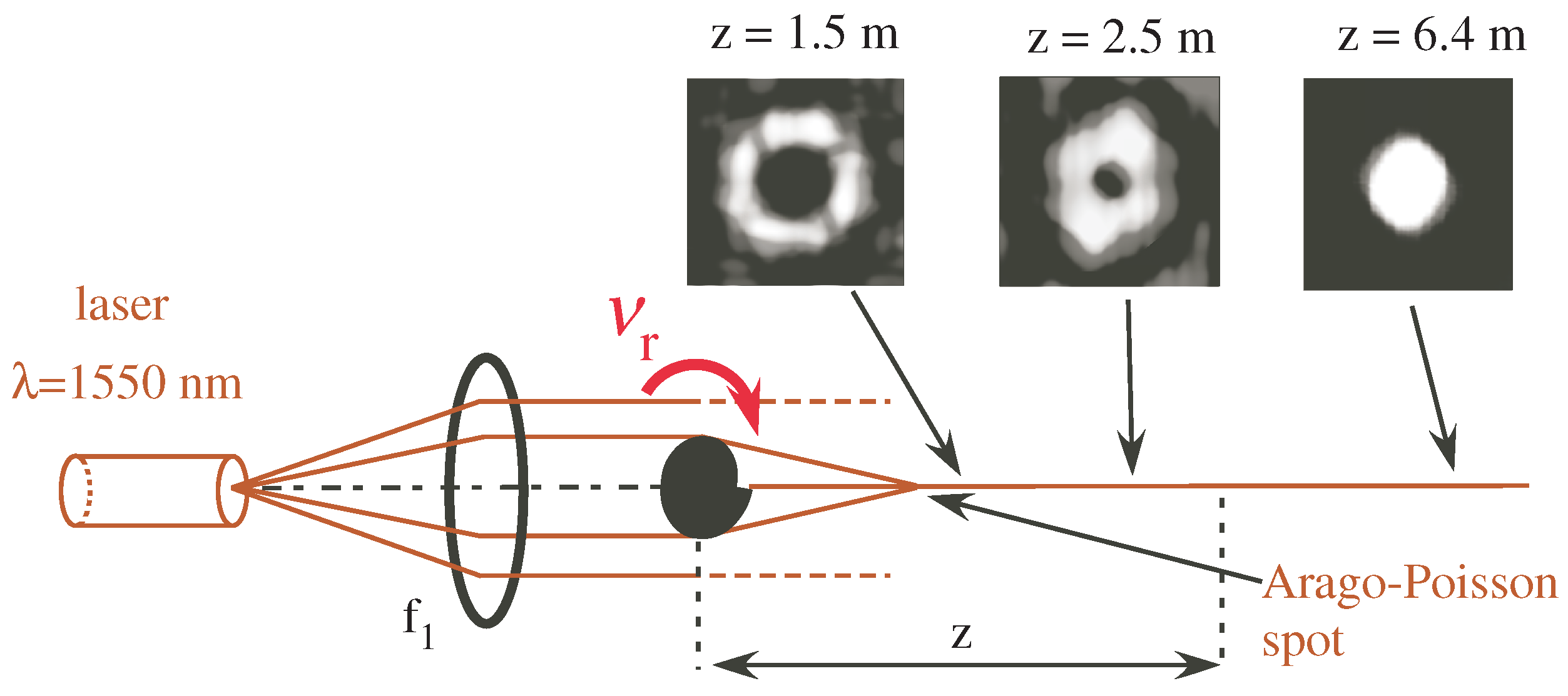
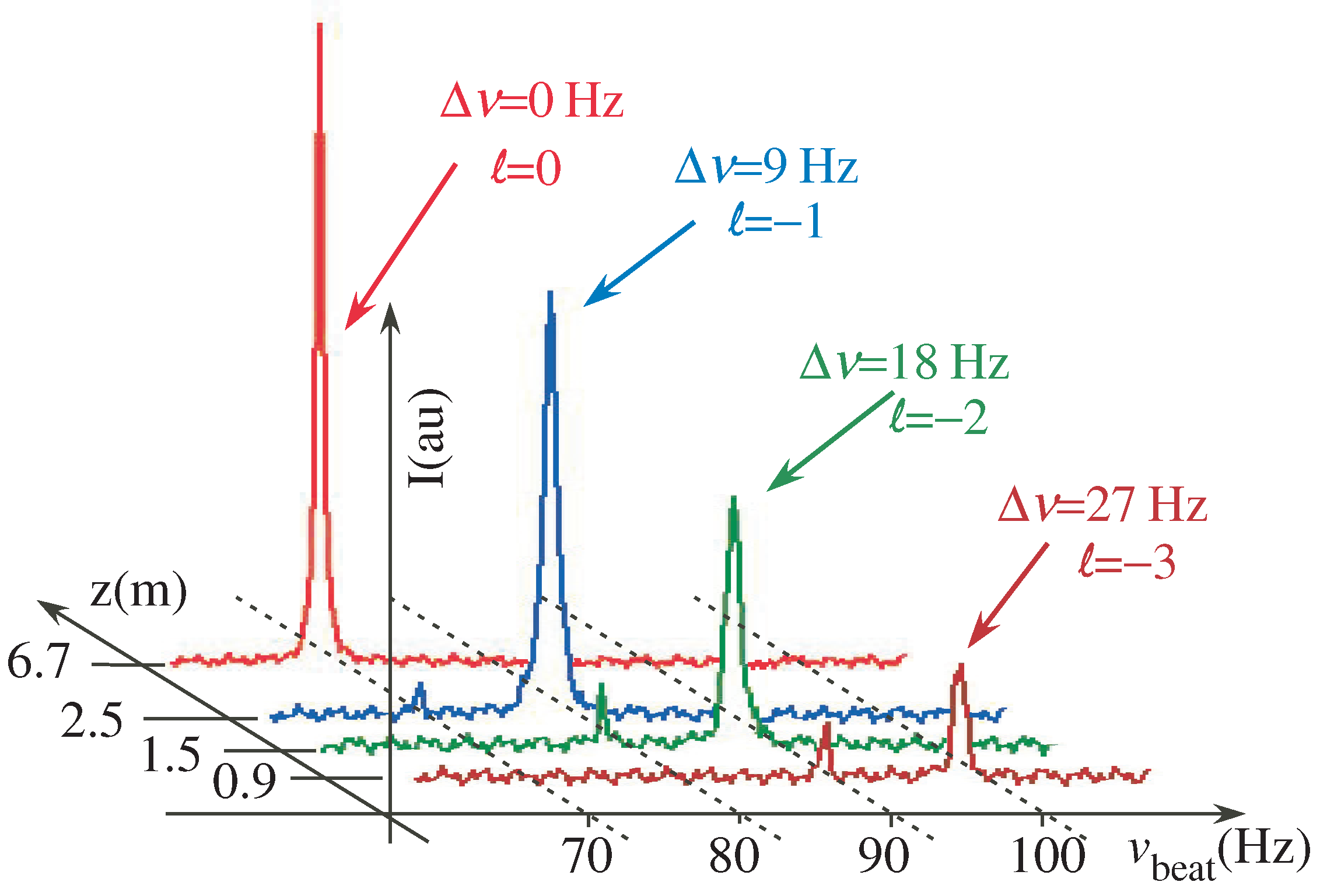
In the case of the generation of a dark spot, it is worth noting that the OAM carried by the Arago–Poisson spot changes during propagation. This has been verified experimentally, as shown in Figure 12 which also presents the experimental set-up. Very far from the occulting object, the spot has lost its OAM character and does not carry OAM any more. It looks like the usual Arago–Poisson spot. However, close to the occulting object, the beam carries OAM. In addition, its topological charge increases. This can also be evidenced on Figure 13.
As the occulting disk is set into rotation, the phase distribution of the diffracted beam is going to rotate accordingly, with a frequency that depends on the topological charge of the Arago–Poisson spot and on the rotation frequency of the object ν r . In fact, it is nothing other than a rotational Doppler effect [101]. This effect is the counterpart of the usual linear Doppler effect for rotating bodies. It can be observed when the topological charge changes upon interaction with the rotating object. Since the incoming plane wave is transformed into a beam carrying OAM, this is the case here. The frequency shift is then equal to ν r .
This indeed means that since the topological charge changes during propagation, the optical frequency of the spot must also change during propagation. This counterintuitive assumption has been verified experimentally [102] and is evidenced in Figure 13. The frequency has been measured with a self-heterodyne technique, with a beat signal against a reference signal that has been shifted thanks to acousto-optic modulators. It is clearly seen that the frequency changes as the distance z between the occulting disk and the detection varies. Furthermore, and above all, the frequency changes in a discrete manner by multiples of the rotating frequency of the object. For practical applications, the rotating occulting disk may also be mimicked by a spatial light modulator, for example.
Aside from this somewhat upsetting consequence, this may have several practical applications. Let us detail one of them. Such a device can address a signal at a given specific point at a given distance from the source. The laser can be tuned to a narrow resonance that could be either an atomic resonance [103,104], a nonlinear optical resonance [103,104,105], or electromagnetic-induced transparency [106]. These resonances could be in the 10s of Hertz range or below. Then, a cell with a medium subjected to such resonances could be placed just after the occulting object in order to allow only a single frequency associated with a single topological charge to be transmitted (for example, = 2 ). Then, only a specific point in the shadow of the object and over a limited distance would be subject to optical radiation. Thus, transmissions would be much more discreet and less subject to spying. Furthermore, it would also reduce the electromagnetic pollution in the neighborhood. This type of technique could also be adapted to radio transmission, since the Arago–Poisson spot also exists in the radio domain.

4. Conclusions

In this article, we have discussed the origin of the Arago–Poisson spot and its theoretical description. In particular, we have isolated a fundamental finite limit to the spot size. It could, however, be diminished by increasing the size of the occulting beam and getting closer to it. Nevertheless, this comes at the expense of the beam intensity. In the case of an incoming beam that carries orbital angular momentum, the bright Arago–Poisson is replaced by a dark spot surrounded by a small annular bright ring. Furthermore, such beam is a self-healing, non-diffracting beam, with supra-luminic properties. Several applications in different domains have been considered, and 100 nm traps for 200 nm diameter fluorescent particles have been realized. The particles are trapped in the evanescence of an Arago–Poisson spot. Smaller traps for molecules or atoms can be considered. It has also been shown that the Arago–Poisson beam can change its nature (topological charge) and (most surprisingly) its frequency during propagation. This could have applications, for example, in telecommunications in order to send a signal at a very precise given position, without perturbing or polluting the vicinity of the point.

Author Contributions

The authors participated equally in this work. All authors have read and agreed to the published version of the manuscript.

Funding

This research received no external funding.

Data Availability Statement

Data underlying the results presented in this paper are not publicly available at this time but may be obtained from the authors upon reasonable request.

Acknowledgments

The authors would like to thank M. Leseignoux (Luminbird, Lannion) for her help, H. Tabuteau ( Université de Rennes) for the fruitful discussions, and J.R. Thébaut and S. Boutros (Université de Rennes) for the technical assistance.

Conflicts of Interest

The authors declare no conflict of interest.

References

  1. Bertrand, J. Eloge Historique de Léon Foucault: Lu Dans la Séance Publique Annuelle du 6 Février 1882; Institut de France: Paris, France, 1882. [Google Scholar]
  2. Born, M.; Wolf, E. Principles of Optics: Electromagnetic Theory of Propagation, Interference and Diffraction of Light; Elsevier: Amsterdam, The Netherlands, 2013. [Google Scholar]
  3. Hecht, E. Optics, 5th ed.; Pearson: London, UK, 2015. [Google Scholar]
  4. Aspect, A. From Huygens’ waves to Einstein’s photons: Weird light. C. R. Phys. 2017, 18, 498–503. [Google Scholar] [CrossRef]
  5. Siegman, A.E. Lasers; University Science Books: Herndon, VA, USA, 1986. [Google Scholar]
  6. Chauvat, D.; Emile, O.; Brunel, M.; Le Floch, A. Direct measurement of the central fringe velocity in Young-type experiments. Phys. Lett. A 2002, 295, 78–80. [Google Scholar] [CrossRef]
  7. Chauvat, D.; Emile, O.; Brunel, M.; Le Floch, A. Huygens’ principle and Young’s experiment in the propagation of light beams. Am. J. Phys. 2003, 71, 1196–1198. [Google Scholar] [CrossRef]
  8. Piksarv, P.; Bowlan, P.; Lohmus, M.; Valtna-Lukner, H.; Trebino, R.; Saari, P. Diffraction of ultrashort Gaussian pulses within the framework of boundary diffraction wave theory. J. Opt. 2011, 14, 015701. [Google Scholar] [CrossRef]
  9. Kim, M.S.; Scharf, T.; Etrich, C.; Rockstuhl, C.; Peter, H.H. Longitudinal-differential interferometry: Direct imaging of axial superluminal phase propagation. Opt. Lett. 2012, 37, 305–307. [Google Scholar] [CrossRef] [PubMed]
  10. Xiafukaiti, A.; Lagrosas, N.; Shiina, T. Exploration for adequate non-diffractive beam generation in dense scattering media. Sci. Rep. 2022, 12, 8824. [Google Scholar] [CrossRef] [PubMed]
  11. Emile, O.; Emile, J. Experimental analysis of submicrometer optical intensity distributions after an opaque disk. Appl. Opt. 2020, 59, 1678–1683. [Google Scholar] [CrossRef]
  12. Evans, P.; Rogers, K.; Chan, J.; Rogers, J.; Dicken, A. High intensity X-ray diffraction in transmission mode employing an analog of Poisson’s spot. Appl. Phys. Lett. 2010, 97, 204101. [Google Scholar] [CrossRef]
  13. Macaulay, E.J.; Hartmann, W.M.; Rakerd, B. The acoustical bright spot and mislocalization of tones by human listeners. J. Acoust. Soc. Am. 2010, 127, 1440–1449. [Google Scholar] [CrossRef]
  14. Zhang, H.; Fan, X. Poisson-Arago spot for gravitational waves. Sci. China Phys. Mech. Astron. 2021, 64, 120462. [Google Scholar] [CrossRef]
  15. Reisinger, T.; Patel, A.A.; Reingruber, H.; Fladischer, K.; Ernst, W.E.; Bracco, G.; Smith, H.I.; Holst, B. Poisson’s spot with molecules. Phys. Rev. A 2009, 79, 053823. [Google Scholar] [CrossRef]
  16. Eder, S.; Reisinger, T.; Greve, M.; Bracco, G.; Holst, B. Focusing of a neutral helium beam below one micron. New J. Phys. 2012, 14, 073014. [Google Scholar] [CrossRef]
  17. Sommerfeld, A. Lectures on Theoretical Physics: Optics; Academic Press: Cambridge, MA, USA, 1954; Volume 4. [Google Scholar]
  18. Dauger, D.E. Simulation and study of Fresnel diffraction for arbitrary two-dimensional apertures. Comput. Phys. 1996, 10, 591–604. [Google Scholar] [CrossRef]
  19. Horváth, Z.; Bor, Z. Diffraction of short pulses with boundary diffraction wave theory. Phys. Rev. E 2001, 63, 026601. [Google Scholar] [CrossRef]
  20. Harvey, J.E.; Forgham, J.L. The spot of Arago: New relevance for an old phenomenon. Am. J. Phys. 1984, 52, 243–247. [Google Scholar] [CrossRef]
  21. Fischer, P.; Skelton, S.E.; Leburn, C.G.; Streuber, C.T.; Wright, E.M.; Dholakia, K. The dark spots of Arago. Opt. Express 2007, 15, 11860–11873. [Google Scholar] [CrossRef]
  22. Emile, O.; Voisin, A.; Niemiec, R.; de Lesegno, B.V.; Pruvost, L.; Ropars, G.; Emile, J.; Brousseau, C. Dark zone in the centre of the Arago-Poisson diffraction spot of a helical laser beam. EPL 2013, 101, 54005. [Google Scholar] [CrossRef]
  23. Yao, A.M.; Padgett, M.J. Orbital angular momentum: Origins, behavior and applications. Adv. Opt. Photonics 2011, 3, 161–204. [Google Scholar] [CrossRef]
  24. Barnett, S.M.; Babiker, M.; Padgett, M.J. Optical orbital angular momentum. Phil. Trans. R. Soc. A 2017, 375, 20150444. [Google Scholar] [CrossRef]
  25. Papathanasopoulos, A.; Rahmat-Samii, Y. Fundamentals of Orbital Angular Momentum Beams. In Electromagnetic Vortices; John Wiley & Sons, Ltd.: Hoboken, NJ, USA, 2021; Chapter 1; pp. 1–32. [Google Scholar]
  26. Hebri, D.; Rasouli, S.; Dezfouli, A.M. Theory of diffraction of vortex beams from structured apertures and generation of elegant elliptical vortex Hermite-Gaussian beams. J. Opt. Soc. Am. A 2019, 36, 839–852. [Google Scholar] [CrossRef]
  27. Emile, O.; Emile, J.; Tabuteau, H. Nanoscale optical trap for fluorescent nanoparticles. EPL 2020, 129, 58001. [Google Scholar] [CrossRef]
  28. Girard, C.; Dereux, A. Near-field optics theories. Rep. Prog. Phys. 1996, 59, 657. [Google Scholar] [CrossRef]
  29. Khonina, S.N.; Ustinov, A.V. Very compact focal spot in the near-field of the fractional axicon. Opt. Commun. 2017, 391, 24–29. [Google Scholar] [CrossRef]
  30. Huang, F.M.; Zheludev, N.I. Super-Resolution without Evanescent Waves. Nano Lett. 2009, 9, 1249–1254. [Google Scholar] [CrossRef]
  31. Khonina, S.N.; Golub, I. Engineering the smallest 3D symmetrical bright and dark focal spots. J. Opt. Soc. Am. A 2013, 30, 2029–2033. [Google Scholar] [CrossRef]
  32. Quabis, S.; Dorn, R.; Eberler, M.; Glöckl, O.; Leuchs, G. Focusing light to a tighter spot. Opt. Commun. 2000, 179, 1–7. [Google Scholar] [CrossRef]
  33. Pendry, J.B. Negative refraction makes a perfect lens. Phys. Rev. Lett. 2000, 85, 3966. [Google Scholar] [CrossRef]
  34. Yen, A. Rayleigh or Abbe? Origin and naming of the resolution formula of microlithography. J. Micro/Nanolithogr. MEMS 2020, 19, 040501. [Google Scholar] [CrossRef]
  35. Harland, M.; Khonina, S.N.; Golub, I. Enlightening Arago–Poisson spot using structured light. Appl. Opt. 2021, 60, 7432–7436. [Google Scholar] [CrossRef]
  36. Mestre, M.; Diry, F.; Viaris de Lesegno, B.; Pruvost, L. Cold atom guidance by a holographically-generated Laguerre-Gaussian laser mode. Eur. Phys. J. D 2010, 57, 87. [Google Scholar] [CrossRef]
  37. Carrat, V.; Cabrera-Gutiérrez, C.; Jacquey, M.; Tabosa, J.W.; de Lesegno, B.V.; Pruvost, L. Long-distance channeling of cold atoms exiting a 2D magneto-optical trap by a Laguerre—Gaussian laser beam. Opt. Lett. 2014, 39, 719–722. [Google Scholar] [CrossRef]
  38. McGloin, D.; Dholakia, K. Bessel beams: Diffraction in a new light. Contemp. Phys. 2005, 46, 15–28. [Google Scholar] [CrossRef]
  39. Khonina, S.N.; Kazanskiy, N.L.; Karpeev, S.V.; Butt, M.A. Bessel beam: Significance and applications—A progressive review. Micromachines 2020, 11, 997. [Google Scholar] [CrossRef]
  40. Durnin, J.; Miceli Jr, J.; Eberly, J.H. Diffraction-free beams. Phys. Rev. Lett. 1987, 58, 1499. [Google Scholar] [CrossRef]
  41. Cox, A.; D’Anna, J. Constant-axial-intensity nondiffracting beam. Opt. Lett. 1992, 17, 232–234. [Google Scholar] [CrossRef]
  42. Ren, Y.X.; He, H.; Tang, H.; Wong, K.K. Non-diffracting light wave: Fundamentals and biomedical applications. Front. Phys. 2021, 9, 698343. [Google Scholar] [CrossRef]
  43. Paterson, C.; Smith, R. Higher-order Bessel waves produced by axicon-type computer-generated holograms. Opt. Commun. 1996, 124, 121–130. [Google Scholar] [CrossRef]
  44. Tiwari, S.K.; Mishra, S.R.; Ram, S.P.; Rawat, H.S. Generation of a Bessel beam of variable spot size. Appl. Opt. 2012, 51, 3718–3725. [Google Scholar] [CrossRef] [PubMed]
  45. Zhang, N.; Ye, J.S.; Feng, S.F.; Wang, X.K.; Han, P.; Sun, W.F.; Zhang, Y.; Zhang, X.C. Generation of long-distance stably propagating Bessel beams. OSA Contin. 2021, 4, 1223–1233. [Google Scholar] [CrossRef]
  46. Zhang, X.; Zhang, X.T.; Ye, J.S.; Feng, S.F.; Wang, X.K.; Han, P.; Sun, W.F.; Zhang, Y. Generation of stable propagation Bessel beams and axial multifoci beams with binary amplitude filters. J. Opt. Soc. Am. A 2023, 40, 1425–1433. [Google Scholar] [CrossRef] [PubMed]
  47. Zhi, Z.; Na, Q.; Xie, Q.; Chen, B.; Li, Y.; Liu, X.; Li, X.; Wang, L.; Lo, G.; Song, J. On-chip generation of Bessel—Gaussian beam via concentrically distributed grating arrays for long-range sensing. Light Sci. Appl. 2023, 12, 92. [Google Scholar] [CrossRef]
  48. Fahrbach, F.O.; Simon, P.; Rohrbach, A. Microscopy with self-reconstructing beams. Nat. Photonics 2010, 4, 780–785. [Google Scholar] [CrossRef]
  49. Vettenburg, T.; Dalgarno, H.I.; Nylk, J.; Coll-Lladó, C.; Ferrier, D.E.; Čižmár, T.; Gunn-Moore, F.J.; Dholakia, K. Light-sheet microscopy using an Airy beam. Nat. Methods 2014, 11, 541–544. [Google Scholar] [CrossRef]
  50. Planchon, T.A.; Gao, L.; Milkie, D.E.; Davidson, M.W.; Galbraith, J.A.; Galbraith, C.G.; Betzig, E. Rapid three-dimensional isotropic imaging of living cells using Bessel beam plane illumination. Nat. Methods 2011, 8, 417–423. [Google Scholar] [CrossRef]
  51. Liu, J.T.; Glaser, A.K.; Bera, K.; True, L.D.; Reder, N.P.; Eliceiri, K.W.; Madabhushi, A. Harnessing non-destructive 3D pathology. Nat. Biomed. Eng. 2021, 5, 203–218. [Google Scholar] [CrossRef]
  52. Suchand Sandeep, C.; Khairyanto, A.; Aung, T.; Vadakke Matham, M. Bessel Beams in Ophthalmology: A Review. Micromachines 2023, 14, 1672. [Google Scholar] [CrossRef]
  53. Garcés-Chávez, V.; McGloin, D.; Melville, H.; Sibbett, W.; Dholakia, K. Simultaneous micromanipulation in multiple planes using a self-reconstructing light beam. Nature 2002, 419, 145–147. [Google Scholar] [CrossRef]
  54. Chu, X. Analytical study on the self-healing property of Bessel beam. Eur. Phys. J. D 2012, 66, 259. [Google Scholar] [CrossRef]
  55. Aiello, A.; Agarwal, G.S. Wave-optics description of self-healing mechanism in Bessel beams. Opt. Lett. 2014, 39, 6819–6822. [Google Scholar] [CrossRef] [PubMed]
  56. Grunwald, R.; Bock, M. Needle beams: A review. Adv. Phys. X 2020, 5, 1736950. [Google Scholar] [CrossRef]
  57. Shen, Y.; Pidishety, S.; Nape, I.; Dudley, A. Self-healing of structured light: A review. J. Opt. 2022, 24, 103001. [Google Scholar] [CrossRef]
  58. Mphuthi, N.; Botha, R.; Forbes, A. Are Bessel beams resilient to aberrations and turbulence? J. Opt. Soc. Am. A 2018, 35, 1021–1027. [Google Scholar] [CrossRef]
  59. Valtna-Lukner, H.; Bowlan, P.; Lõhmus, M.; Piksarv, P.; Trebino, R.; Saari, P. Direct spatiotemporal measurements of accelerating ultrashort Bessel-type light bullets. Opt. Express 2009, 17, 14948–14955. [Google Scholar] [CrossRef]
  60. Courvoisier, F.; Stoian, R.; Couairon, A. Ultrafast laser micro-and nano-processing with nondiffracting and curved beams: Invited paper for the section: Hot topics in ultrafast lasers. Opt. Laser Technol. 2016, 80, 125–137. [Google Scholar] [CrossRef]
  61. Mugnai, D.; Ranfagni, A.; Ruggeri, R. Observation of superluminal behaviors in wave propagation. Phys. Rev. Lett. 2000, 84, 4830. [Google Scholar] [CrossRef]
  62. Tian, S.; Xia, X.; Sun, W.; Li, W.; Li, J.; Gu, C. Large-scale ordered silicon microtube arrays fabricated by Poisson spot lithography. Nanotechnology 2011, 22, 395301. [Google Scholar] [CrossRef]
  63. Jung, Y.; Vacic, A.; Sun, Y.; Hadjimichael, E.; Reed, M.A. Mapping of near field light and fabrication of complex nanopatterns by diffraction lithography. Nanotechnology 2012, 23, 045301. [Google Scholar] [CrossRef] [PubMed]
  64. Kaemtner, D.; Prenting, J. Straight Line Reference System (SLRS) for the Adjustment of the X-ray Free-electron Laser (XFEL) at DESY. In Proceedings of the 9th International Workshop on Accelerator Alignment (IWAA), Stanford Linear Accelerator Center (SLAC), Menlo Park, CA, USA, 26–29 September 2006. [Google Scholar]
  65. Luo, T.; He, Z.; Cheng, H.; Zuo, T.; Xiao, S.; Lu, S.; Ke, Z.; Ma, N.; Wang, T.; Liang, J.; et al. A new laser-based alignment method for the multi-slits VSANS in high precision. Nucl. Instrum. Methods A 2021, 1010, 165526. [Google Scholar] [CrossRef]
  66. He, Z.; Wang, T.; Wang, X.; Lu, S.; Liu, H.; Li, X.; Men, L.; Ma, N.; Ke, Z.; Liang, J.; et al. A new laser-based monitoring method for the cryomodule components alignment. Meas. Sci. Technol. 2022, 33, 075201. [Google Scholar] [CrossRef]
  67. Niewiem, W.; Polak, K.; Dusek, M.; Mergelkuhl, D.; Gayde, J.C.; Wieser, A.; Sulc, M. Variation of Structured Laser Beam pattern and optimization for an alignment reference line creation. Opt. Express 2023, 31, 43307–43322. [Google Scholar] [CrossRef]
  68. Erbschloe, D.R. The Spot of Arago and Its Role in Aberration Analysis. Master’s Thesis, University of New Mexico, Albuquerque, NM, USA, 1983. [Google Scholar]
  69. Ovryn, B.; Hovenac, E.A. Coherent forward scattering particle-image velocimetry: Application of Poisson’s spot for velocity measurements in fluids. In Proceedings of the SPIE: Optical Diagnostics in Fluid and Thermal Flow, SPIE, Orlando, FL, USA, 13–14 April 1993; Volume 2005, pp. 338–348. [Google Scholar]
  70. Vanderbei, R.J. Eliminating Poisson’s spot with linear programming. In Proceedings of the Operations Research and Cyber-Infrastructure; Springer: Berlin/Heidelberg, Germany, 2009; pp. 455–467. [Google Scholar]
  71. Lyot, B. The study of the solar corona and prominences without eclipses (George Darwin Lecture, 1939). Mon. Not. R. Astron. Soc. 1939, 99, 580. [Google Scholar]
  72. Kuchner, M.J.; Traub, W.A. A coronagraph with a band-limited mask for finding terrestrial planets. Astrophys. J. 2002, 570, 900. [Google Scholar] [CrossRef]
  73. Guyon, O.; Pluzhnik, E.; Kuchner, M.; Collins, B.; Ridgway, S. Theoretical limits on extrasolar terrestrial planet detection with coronagraphs. Astrophys. J. Suppl. 2006, 167, 81. [Google Scholar] [CrossRef]
  74. Cash, W. Analytic modeling of starshades. Astrophys. J. 2011, 738, 76. [Google Scholar] [CrossRef]
  75. Soto, G.J.; Savransky, D.; Morgan, R. Analytical model for starshade formation flying with applications to exoplanet direct imaging observation scheduling. J. Astron. Telesc. Instrum. Syst. 2021, 7, 021209. [Google Scholar] [CrossRef]
  76. Cocks, F.; Watkins, S.; Walker, M.; Lutz, T.; Sussingham, J. A High-Resolution Solar Telescope Using Dark-Lens Diffractive Optics. Sol. Phys. 2001, 198, 211–222. [Google Scholar] [CrossRef]
  77. Cash, W. The Aragoscope: Ultra-High Resolution Optics at Low Cost; Technical Report; NASA: Washington, DC, USA, 2014. [Google Scholar]
  78. Lotz, J.E.; Koekemoer, A.; Coe, D.; Grogin, N.; Capak, P.; Mack, J.; Anderson, J.; Avila, R.; Barker, E.; Borncamp, D.; et al. The Frontier Fields: Survey design and initial results. Astrophys. J. 2017, 837, 97. [Google Scholar] [CrossRef]
  79. Robertson, B.E. Galaxy formation and reionization: Key unknowns and expected breakthroughs by the james webb space telescope. Ann. Rev. Astron. Astrophys. 2022, 60, 121–158. [Google Scholar] [CrossRef]
  80. Ashkin, A.; Dziedzic, J.M.; Bjorkholm, J.E.; Chu, S. Observation of a single-beam gradient force optical trap for dielectric particles. Opt. Lett. 1986, 11, 288–290. [Google Scholar] [CrossRef]
  81. Grier, D.G. A revolution in optical manipulation. Nature 2003, 424, 810–816. [Google Scholar] [CrossRef]
  82. Neuman, K.C.; Block, S.M. Optical trapping. Rev. Sci. Instrum. 2004, 75, 2787–2809. [Google Scholar] [CrossRef] [PubMed]
  83. Jones, P.H.; Maragò, O.M.; Volpe, G. Optical Tweezers: Principles and Applications; Cambridge University Press: Cambridge, UK, 2015. [Google Scholar]
  84. Bustamante, C.J.; Chemla, Y.R.; Liu, S.; Wang, M.D. Optical tweezers in single-molecule biophysics. Nat. Rev. Methods Primers 2021, 1, 25. [Google Scholar] [CrossRef] [PubMed]
  85. Spesyvtseva, S.E.S.; Dholakia, K. Trapping in a material world. ACS Photonics 2016, 3, 719–736. [Google Scholar] [CrossRef]
  86. Almaas, E.; Brevik, I. Radiation forces on a micrometer-sized sphere in an evanescent field. J. Opt. Soc. Am. B 1995, 12, 2429–2438. [Google Scholar] [CrossRef]
  87. Yoon, Y.Z.; Cicuta, P. Optical trapping of colloidal particles and cells by focused evanescent fields using conical lenses. Opt. Express 2010, 18, 7076–7084. [Google Scholar] [CrossRef] [PubMed]
  88. Emile, O.; Emile, J.; Tabuteau, H. 2-D evanescent trapping of colloids in the vicinity of a micrometer waveguide. EPL 2017, 116, 64003. [Google Scholar] [CrossRef]
  89. Novotny, L.; Bian, R.X.; Xie, X.S. Theory of nanometric optical tweezers. Phys. Rev. Lett. 1997, 79, 645. [Google Scholar] [CrossRef]
  90. Volpe, G.; Quidant, R.; Badenes, G.; Petrov, D. Surface plasmon radiation forces. Phys. Rev. Lett. 2006, 96, 238101. [Google Scholar] [CrossRef]
  91. Juan, M.L.; Righini, M.; Quidant, R. Plasmon nano-optical tweezers. Nat. Photonics 2011, 5, 349–356. [Google Scholar] [CrossRef]
  92. Kotsifaki, D.G.; Chormaic, S.N. Plasmonic optical tweezers based on nanostructures: Fundamentals, advances and prospects. Nanophotonics 2019, 8, 1227–1245. [Google Scholar] [CrossRef]
  93. Tang, X.; Zhang, Y.; Su, W.; Zhang, Y.; Liu, Z.; Yang, X.; Zhang, J.; Yang, J.; Yuan, L. Super-low-power optical trapping of a single nanoparticle. Opt. Lett. 2019, 44, 5165–5168. [Google Scholar] [CrossRef] [PubMed]
  94. Brunetti, G.; Sasanelli, N.; Armenise, M.N.; Ciminelli, C. Nanoscale Optical Trapping by Means of Dielectric Bowtie. Photonics 2022, 9, 425. [Google Scholar] [CrossRef]
  95. Emile, O.; Emile, J. Nanometer optical trap based on stimulated emission in evanescence of a totally reflected Arago spot: Nanometer optical trap for fluorescent nanoparticles. Eur. Phys. J. E 2020, 43, 68. [Google Scholar] [CrossRef] [PubMed]
  96. Haugland, R.P. The handbook: A Guide to Fluorescent Probes and Labeling Technologies; Molecular Probes: Eugene, OR, USA, 2005. [Google Scholar]
  97. Floch, A.L.; Emile, O.; Ropars, G.; Agrawal, G.P. Dynamics and detection of the Newton-Wigner time delays at interfaces using a swivelling method. Sci. Rep. 2017, 7, 9083. [Google Scholar] [CrossRef] [PubMed]
  98. Emile, O.; Le Meur, M.; Emile, J. Light angular momentum of a plane wave diffracted by a two-dimensional object. Phys. Rev. A 2014, 89, 013846. [Google Scholar] [CrossRef]
  99. Emile, O.; Emile, J. Rotation of millimeter-sized objects using ordinary light. Opt. Lett. 2016, 41, 211–214. [Google Scholar] [CrossRef]
  100. Emile, J.; Tabuteau, H.; Emile, O. Rotation of a floating hydrophobic disk: Influence of line tension. Soft Matter 2018, 14, 3829–3833. [Google Scholar] [CrossRef]
  101. Emile, O.; Emile, J. Rotational Doppler Effect: A Review. Ann. Phys. 2023, 535, 2300250. [Google Scholar] [CrossRef]
  102. Emile, O.; Emile, J. Frequency changes during the propagation of a light beam. EPL 2022, 139, 35001. [Google Scholar] [CrossRef]
  103. Hall, J.L. Nobel Lecture: Defining and measuring optical frequencies. Rev. Mod. Phys. 2006, 78, 1279. [Google Scholar] [CrossRef]
  104. Stenholm, S. Foundations of Laser Spectroscopy; Courier Corporation: North Chelmsford, MA, USA, 2012. [Google Scholar]
  105. Chebotayev, V.; Letokhov, V. Nonlinear narrow optical resonances induced by laser radiation. Prog. Quantum Electron. 1975, 4, 111–206. [Google Scholar] [CrossRef]
  106. Fleischhauer, M.; Imamoglu, A.; Marangos, J.P. Electromagnetically induced transparency: Optics in coherent media. Rev. Mod. Phys. 2005, 77, 633. [Google Scholar] [CrossRef]
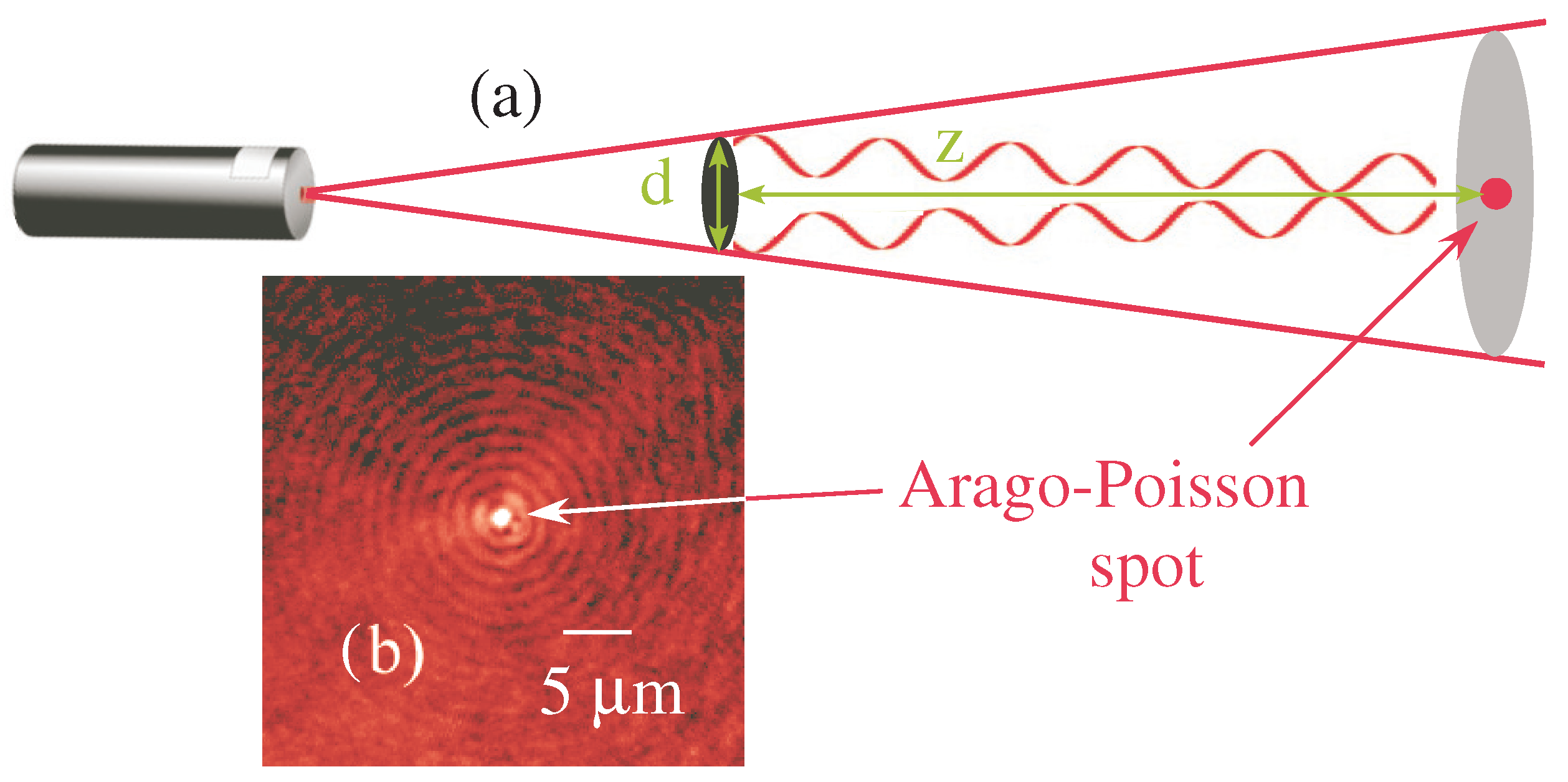
Figure 1. Principle of the Arago–Poisson spot observation. (a) A light beam impinges on an occulting disk (diameter d). The diffracted light interferes in the shadow of the disk on a screen at a distance z from the occulting disk. (b) Example of a picture of the Arago–Poisson spot at a distance of z = 10 cm from the disk, for d = 1 cm and λ = 633 nm.
Photonics 11 00055 g001
Figure 2. Experimental intensity distribution (in arbitrary units) of the dark Arago–Poisson spot for = 4 , z = 200 μ m and a disk diameter of d = 600 μ m. λ = 633 nm.
Photonics 11 00055 g002
Figure 3. Principle of the experiment: a collimated laser beam impinges on a transparent window with an occulting disk. The light is diffracted by the disk and forms a bright spot in the shadow of the disk. The light is collected with an inverted microscope with a × 100 objective. z: distance from the disk, d: diameter of the disk, θ : maximum angle corresponding to the numerical aperture of the objective. We cannot observe a spot at a distance shorter than 100 μ m for a d = 600 μ m disk.
Photonics 11 00055 g003
Figure 4. Variation in the size of the Arago–Poisson spot with the distance from the occulting disk (diameter d = 0.6 mm. As the distances reduce, the size tends to 176 nm. The experimental uncertainty reads in the error bars. The solid line corresponds to the theoretical curve of Equation (1). Inserts, pictures of the Arago–Poisson spots corresponding to the experimental points. Note that the scale changes for each insert.
Photonics 11 00055 g004
Figure 5. Variation in the size of the Arago–Poisson spot with the laser wavelength. The experimental uncertainty reads in the error bars. The solid line corresponds to the theoretical curve of Equation (1), with d = 600 μ m and z = 2 mm.
Photonics 11 00055 g005
Figure 6. Variation in the size of the Arago–Poisson spot with diameter of the occulting disk d. The experimental uncertainty reads in the error bars. The solid line corresponds to the theoretical curve of Equation (1), with λ = 532 nm and z = 2 mm.
Photonics 11 00055 g006
Figure 7. Principle of self-healing for Arago–Poisson spot. (Top): usual situation leading to an Arago–Poisson spot. (Bottom): as a perturbing obstacle (blue diamond) is inserted, in its immediate shadow, the spot disappears. But further on, it reconstructs itself with the same characteristics. The obstacle does not need to be exactly on axis or even symmetric.
Photonics 11 00055 g007
Figure 8. The wavelets emitted by the edges of the occulting disk propagate at a velocity c. During a time interval d t , they travel from N ( t ) to M ( t + d t ) . However, on the axis, the spot travels from M ( t ) to M ( t + d t ) over a distance that is greater than the distance from N ( t ) to M ( t + d t ) , thus at an apparent faster-than-light velocity.
Photonics 11 00055 g008
Figure 9. Experimental set up: (a) an Arago–Poisson spot originates from the diffraction of a 488 nm collimated laser beam diffracted by a chromium occulting disk deposited on a glass lamella. First, 200 nm diameter fluorescent colloids flowing within the liquid, are exited with a 470 nm diode. The fluorescence is collected with a X20 microscope objective and a camera. DM: Dichroic Mirror. (b) Details of the experimental set-up. The Arago–Poisson spot is under total internal reflection on the glass/liquid interface. The particles are trapped by the evanescent Arago–Poisson spot.
Photonics 11 00055 g009
Figure 10. Principle of the trapping mechanism. The particle is pushed to the upper side of the channel by the radiation pressure from the 470 nm diode that excites the particle. Then, the particle reemits light in a stimulated way at 488 nm in the outgoing evanescent wave. The particle is thus pushed towards the center of the trap by the force F. Insert shows an example of a trapped particle.
Photonics 11 00055 g010
Figure 11. (Left): experimental situation for the realization of an evanescent trap. The Arago–Poisson spot is under total internal reflection. As the size of the occulting disk increases, the angle of incidence of the spot on the surface increases. (Right): variation of the radius of the trap size versus the angle of incidence. The diameter of the occulting disk is recalled for each size. The solid line corresponds to the variation in the Goos–Hänchen shift ( δ G H ) with the angle of incidence.
Photonics 11 00055 g011
Figure 12. Experimental set-up. The infrared light from a 1550 nm impinges on a dissymmetric object. The diffracted Arago–Poisson spot on the axis of the light, close to the occulting dissymmetric object, has a donut-shaped structure (see insets) and carries OAM. f 1 : focusing lens. The occulting object can be rotated at a given frequency ν r . Inserts: picture of the spot intensity along the axis for different positions z. The scale is different for each insert.
Photonics 11 00055 g012
Figure 13. Frequency shift of the diffracted beam as a function of the distance from the occulting disk z. The object rotates at a frequency ν = 9 Hz. The frequency shift is measured with a self-heterodyne technique. The reference beam is frequency shifted with acousto-optic modulators.
Photonics 11 00055 g013
Disclaimer/Publisher’s Note: The statements, opinions and data contained in all publications are solely those of the individual author(s) and contributor(s) and not of MDPI and/or the editor(s). MDPI and/or the editor(s) disclaim responsibility for any injury to people or property resulting from any ideas, methods, instructions or products referred to in the content.