Article

FSK/ASK Orthogonal Modulation System Based on Novel Noncoherent Detection and Electronic Dispersion Compensation for Short-Reach Optical Communications

School of Information Science and Engineering, Shandong University, Qingdao 266237, China
*
Authors to whom correspondence should be addressed.
Photonics 2024, 11(1), 44; https://doi.org/10.3390/photonics11010044
Submission received: 21 November 2023 / Revised: 23 December 2023 / Accepted: 29 December 2023 / Published: 31 December 2023
(This article belongs to the Special Issue Time and Frequency Transfer over Fiber Link)

Abstract

:
We propose an FSK/ASK orthogonal modulation system based on a novel noncoherent detection (NCD) scheme, aimed at expanding the system capacity for short-reach optical communications cost-effectively. In the transmitter, the FSK optical signal is generated by simple frequency modulation through a directly modulated distributed feedback laser. Subsequently, by utilizing a Mach–Zehnder modulator for ASK modulation, the FSK/ASK optical signal is obtained. The novel and low-complexity NCD receiver consists of an intensity detection branch and a frequency detection branch. The frequency detection branch is composed of an optical differentiator, a photodetector, and frequency extraction circuits. Notably, the proposed NCD scheme overcomes the limitation of the traditional FSK/ASK-NCD receiver stemming from the trade-off between the detected signal quality of the amplitude and frequency. Furthermore, electronic dispersion compensation (EDC) is available. Through numerical simulations, our findings demonstrate that the proposed FSK/ASK-NCD system, assisted by EDC, achieves a remarkable 100 km transmission span for both 40 Gbps 2FSK/2ASK and 60 Gbps 2FSK/4ASK modulation formats, which surpasses the 2ASK-DD and the 4ASK-DD systems, where the maximum achievable spans are limited to less than 20 km. These results underscore the potential of the proposed system as a robust candidate for future passive optical access networks.

1. Introduction

In recent years, the explosive proliferation of multimedia services and applications, such as high-quality live videos, artificial intelligence, the Internet of Things, and autonomous vehicles, has significantly increased the demand for bandwidth at every level of optical networks. Empowered by complex modulation and coherent detection (CM-CD) with newly developed digital signal processing (DSP), long-haul optical networks have witnessed a remarkable capacity evolution, achieving a multi-terabit level [1]. In short-reach optical networks, upgrading present systems to support the burgeoning traffic is also imperative. Unfortunately, simple and low-cost intensity modulation (IM) with direct detection (DD) fails to offer higher bandwidth due to its inherent limitations in spectral efficiency. Moreover, the CM-CD technology adopted in long-haul optical networks is prevented from being employed in short-reach applications due to its high cost and complexity. Therefore, compromises that are suitable for cost-effective short-reach networks have been extensively investigated, e.g., four-level pulse amplitude modulation (4-PAM) standardized by IEEE P802.3bs in data center interconnects [2], quadrature amplitude modulation (QAM) with self-homodyne coherent detection [3], star QAM modulation with interferometric direct detection [4], a variety of modulation formats in Stokes space with Stokes vector detection [5], and single-sideband discrete-multitone with direct detection [6]. Nevertheless, each of these systems exhibits certain drawbacks, including limited spectral efficiency, complexity in configuration and implementation, and so on.
The orthogonal modulation format combining frequency shift keying (FSK) and amplitude shift keying (ASK), which is detected by a noncoherent detection (NCD) optical receiver consisting of a photodetector (PD) for amplitude detection and an FSK receiver incorporating an optical bandpass filter and a PD for frequency detection, has attracted growing attention in high-speed optical packet networks for its notable merits of simple detection and high-spectral efficiency [7,8,9]. Nevertheless, in these systems, a trade-off exists between the detected signal quality of ASK and FSK. Specifically, enhancing the amplitude modulation depth improves the performance of the detected amplitude signal at the expense of the deterioration of the detected frequency signal, and vice versa [7]. This limitation arises from the fact that the detected signal of the FSK receiver includes a portion of amplitude information alongside. Based on a novel NCD scheme to overcome this limitation, we propose an FSK/ASK orthogonal modulation system aimed at increasing the bandwidth in a cost-efficient manner for short-reach optical networks. In the transmitter, the FSK signal is generated by a directly modulated distributed feedback (DFB) laser, assisted by a saturated semiconductor optical amplifier (SOA) to mitigate power fluctuation. Subsequently, by utilizing a Mach–Zehnder modulator (MZM) for amplitude modulation, the FSK/ASK optical signal is obtained. After fiber transmission, the FSK/ASK optical signal is received by a novel and low-complexity NCD receiver, which comprises an intensity detection branch including a normal PD and an electrical low-pass filter, as well as a frequency detection branch including an optical differentiator, a normal PD, and an electrical low-pass filter. In the frequency detection branch, the frequency information is transferred to the intensity through an optical differentiator and mixed with the amplitude information. After PD detection and noise suppression through the low-pass filter, the frequency information is accurately extracted through the electrical calculation circuits. Notably, compared with the traditional NCD system mentioned above, the detected signal of the frequency detection branch is independent of the amplitude information, eliminating the trade-off between the detected signal quality of amplitude and frequency. Furthermore, the precise detection of intensity and frequency information enables electronic dispersion compensation (EDC), presenting a significant advantage in capacity improvement for the proposed NCD receiver. Since there are neither expensive components nor complicated technology involved, the proposed FSK/ASK-NCD system is expected as a cost-effective approach to enhance the capacity for short-reach optical communications.
The rest of this paper is organized as follows. The fundamental operating principle of the proposed FSK/ASK-NCD system with EDC is elucidated with mathematical expression. In Section 3, we have studied the performance of the proposed FSK/ASK-NCD system, taking the 40 Gbps 2FSK/2ASK and the 60 Gbps 2FSK/4ASK formats as examples, respectively. For comparison, the conventional 2ASK-DD system and the 4ASK-DD system under the same condition have also been simulated. Finally, Section 4 summarizes and concludes this paper.

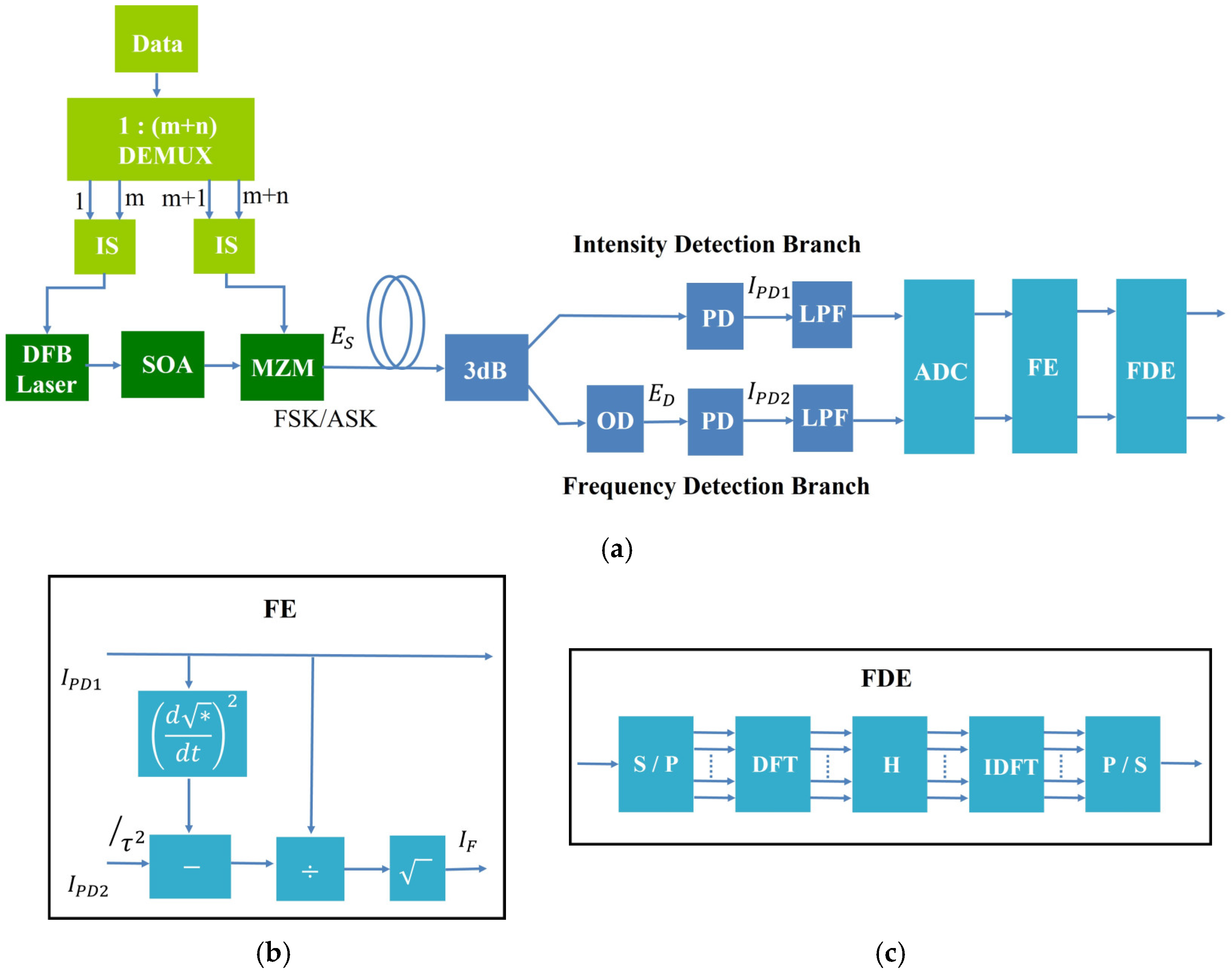
2. Operating Principle

The fundamental operating principle underpinning the proposed FSK/ASK orthogonal modulation system based on novel NCD and EDC is illustrated in Figure 1. In the electrical part of the transmitter, the data signal is parallelized with a 1 : m + n demultiplexer. Subsequently, the first m and the last   n parallelized data streams are fed into separate impulse shapers to generate the electrical message signals for FSK and ASK modulation, respectively. In the optical part of the transmitter, a DFB laser is directly modulated by the electrical signals, achieving FSK modulation through the parasitic frequency modulation (FM) in accompanying IM. The power fluctuation is suppressed by the saturation amplification of an inline SOA, and a relatively pure FSK optical signal is obtained. Then, this FSK optical signal undergoes amplitude modulation via an MZM, yielding the FSK/ASK optical signal, which can be expressed as follows [10]:
E S t = a ( t ) e x p j ( ω 0 t + 0 t f τ   d τ + φ 0 ) ,
where a ( t ) is the encoded amplitude information, ω 0 the carrier angular frequency, f τ the encoded frequency information, and φ 0 the initial phase.
After fiber transmission, the FSK/ASK optical signal is detected by a novel NCD receiver with low complexity. The NCD receiver is composed of two branches for intensity and frequency detection, respectively. The optical differentiator in the frequency detection branch plays the pivotal role of transferring frequency information to intensity information, which can be detected by a normal PD directly. Ideally, the transfer function of the optical differentiator is linear and can be written as j τ ( ω ω 0 ) [11]. Assume the input signal to the receiver is an ideal undistorted FSK/ASK optical signal as defined in Equation (1). Subsequently, the output optical signal from the optical differentiator can be written as:
E D t = 2 2 τ d E S t d t j ω 0 E S t   = 2 2 τ a t + j a t f t e x p j ( ω 0 t + 0 t f τ   d τ + φ 0 ) .
We can see that the frequency information is included in the amplitude of the output signal from the optical differentiator as E D t . After PD, we obtain the output photocurrent that is proportional to the optical power of E D , i.e.,
I P D 2 t = R 2 E D t · E D * t = R 2 τ 2 2 a t 2 + a 2 t f t 2 ,
where R 2 represents the responsivity of the PD in the frequency detection branch. With the assistance of frequency extraction circuits, the frequency information can be demodulated. The principle of frequency extraction operation is shown in Figure 1b. By utilizing the intensity information detected by the intensity detection branch to eliminate the amplitude components in Equation (3), we can extract the frequency information. The output signal from the FE module is
  I F = I P D 2 τ 2 d I P D 1 d t 2 / I P D 1 f t ,
  I P D 1 t = R 1 2 a t 2 .
Here, R 1 denotes the responsivity of the PD in the intensity detection branch, which is approximately equal to that in the frequency detection branch. Equations (4) and (5) demonstrate successful detection of the encoded frequency and amplitude information through the collaboration between the intensity and the frequency detection branch in the NCD receiver. The analysis of Equation (4) confirms that amplitude information has no influence on the detected signal of the frequency detection branch, thereby obviating the necessity for critical adjustment of the extinction ratio to obtain balanced signal quality of both intensity and frequency in the current NCD receiver for FSK/ASK systems. Additionally, given that f ( t ) and a t in Equations (4) and (5) represent the frequency and amplitude not only for 2FSK and 2ASK, the proposed novel NCD receiver showcases its applicability beyond the realm of 2FSK/2ASK optical signals and is well suited for the detection of higher-level FSK/ASK optical signals.
In practice, the detected signals deviate from the encoded frequency and amplitude information due to the deterioration induced by the inter-symbol interference stemming from fixed group velocity dispersion of the optical fiber. A noteworthy characteristic of the proposed NCD receiver is its capacity to enable EDC, thereby facilitating the recovery of encoded frequency and amplitude information. As shown in Figure 1c, EDC is implemented by a fixed frequency-domain equalizer (FDE). After serial data of the received complex amplitude are divided into blocks by the serial-to-parallel converter (S/P), each block in the time domain is transformed into the frequency domain with the discrete Fourier transform (DFT). The transfer function then equalizes each spectral component [1]:
H = e x p 1 2 j ( β 2 Z ω 2 ) ,
where β 2 is the second order dispersion and Z is the length of fiber. Eventually, the block equalized in the frequency domain is transformed back into the time domain with inverse DFT (IDFT) and converted into serial data by the parallel-to-serial converter (P/S). Both the frequency extraction and EDC are executed through advanced high-speed DSP, since the implementation of these operations based on analog circuits is challenging for high data rates.
In contrast to coherent detection, the proposed NCD scheme offers a distinct advantage in terms of simplicity and cost. The need for a local oscillator laser or intricate phase, frequency, or polarization control is obviated. Moreover, EDC can be accessible in the proposed NCD, which is notably absent in the conventional DD. Therefore, with the assistance of EDC, the proposed FSK/ASK orthogonal modulation system based on the novel NCD holds significant prospects for increasing the capacity of cost-effective short-reach networks.

3. Numerical Simulation Setup and Results

To evaluate the feasibility and effectiveness, simulations are conducted, focusing on the performance analysis of our proposed FSK/ASK-NCD system by taking the transmission of 40 Gbps 2FSK/2ASK and 60 Gbps 2FSK/4ASK as examples. In our proposed FSK/ASK-NCD system, the generation of FSK optical signals relies on direct current modulation within a DFB laser source, while the implementation of higher-speed or higher-level FSK/ASK optical signals necessitates the incorporation of an external FSK modulator [12,13,14,15,16]. Consequently, simulations of higher-speed or higher-level FSK/ASK orthogonal modulation formats are beyond the scope of our consideration in this paper. As an illustrative example, we considered the 40 Gbps 2FSK/2ASK system to elaborate on the simulation models employed for the optical transmitter, optical fiber, and optical receiver.

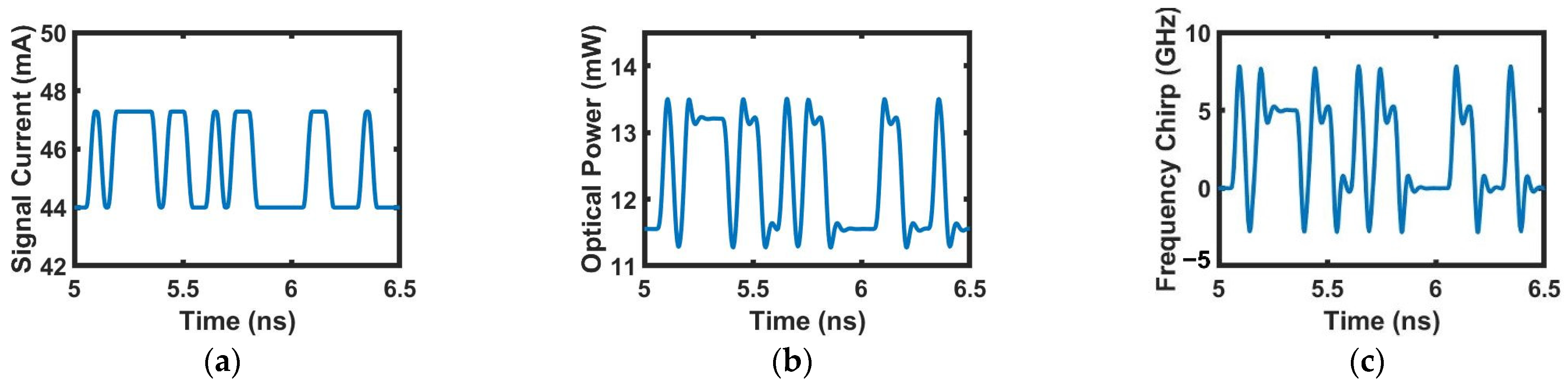
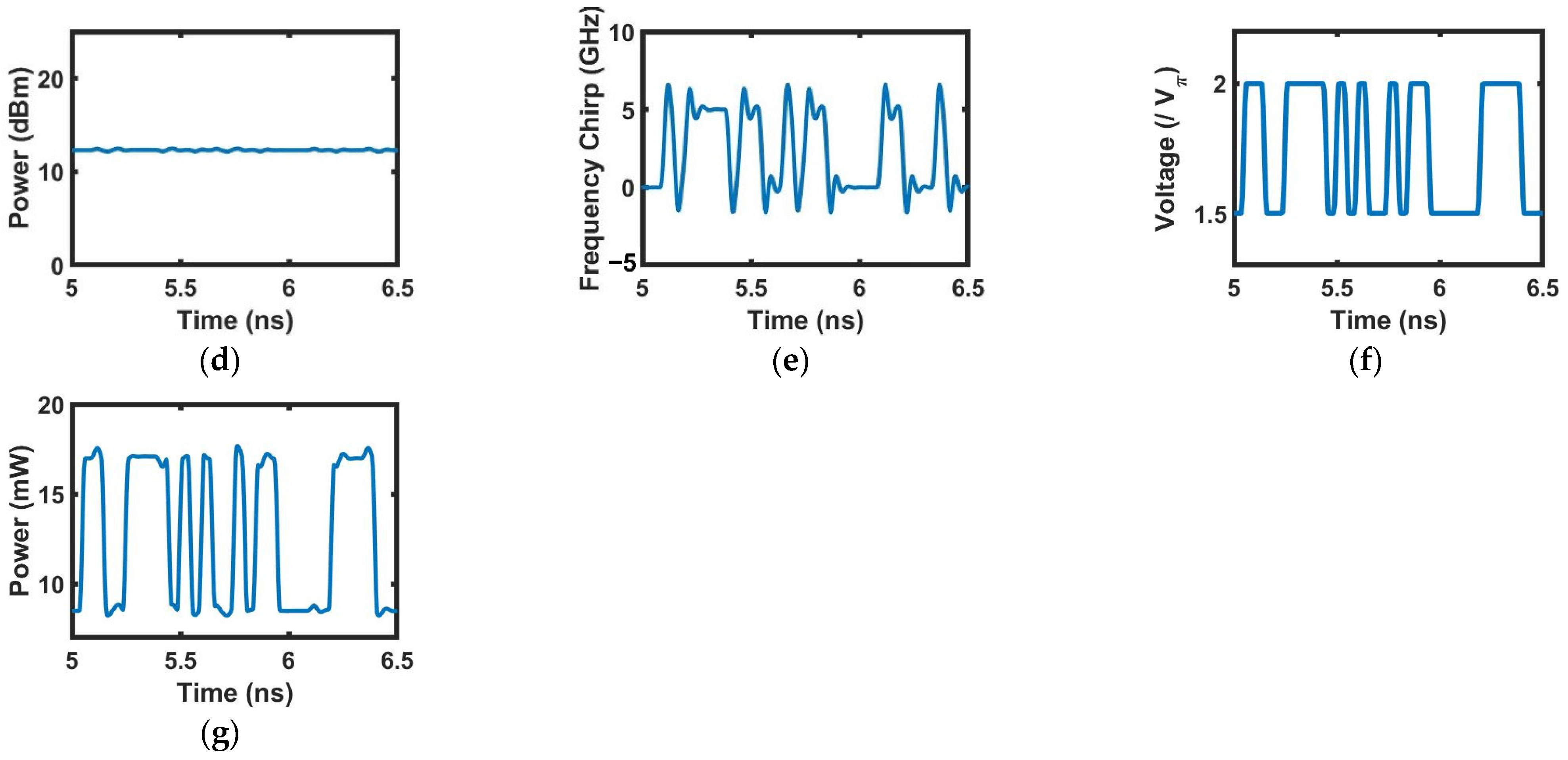
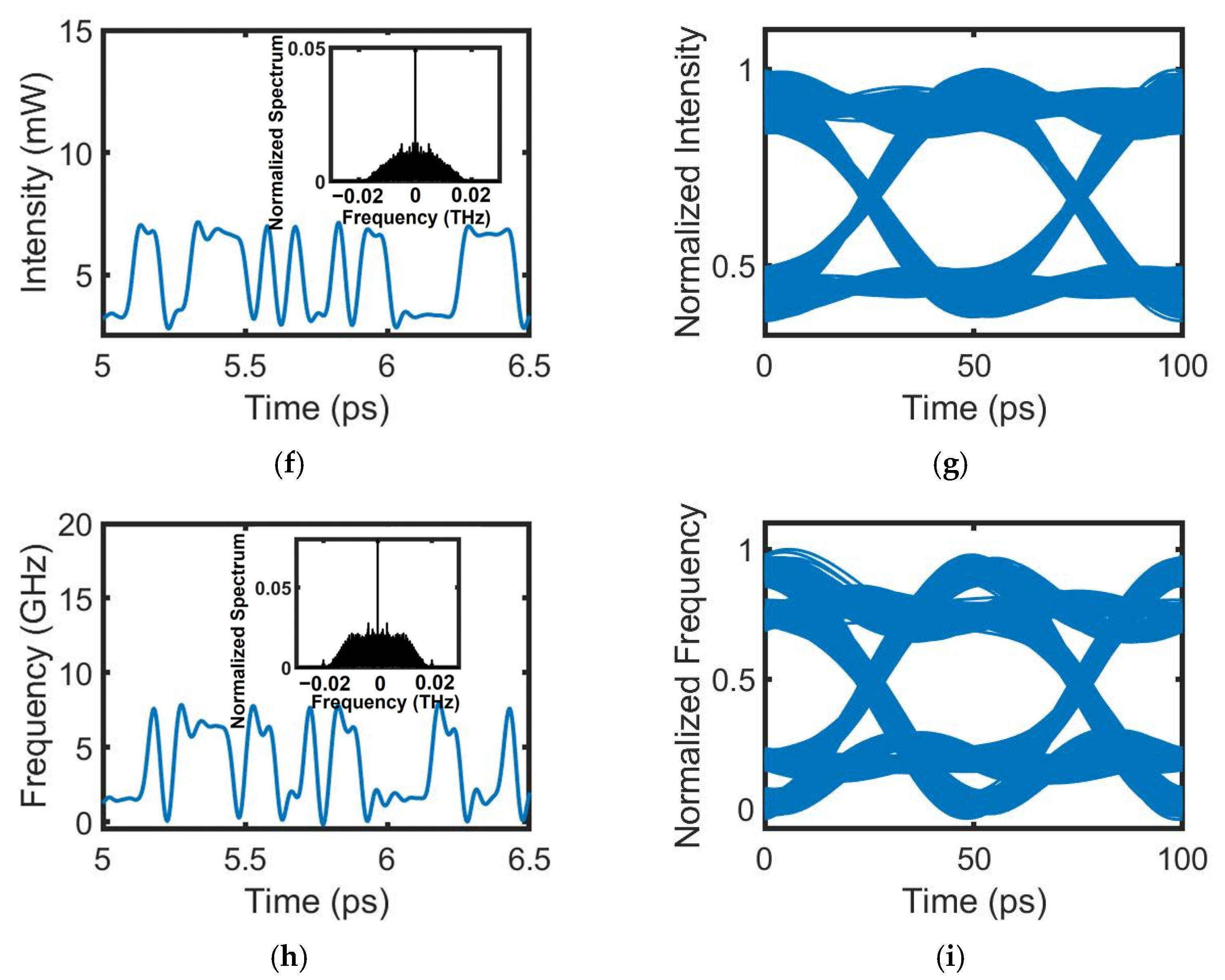
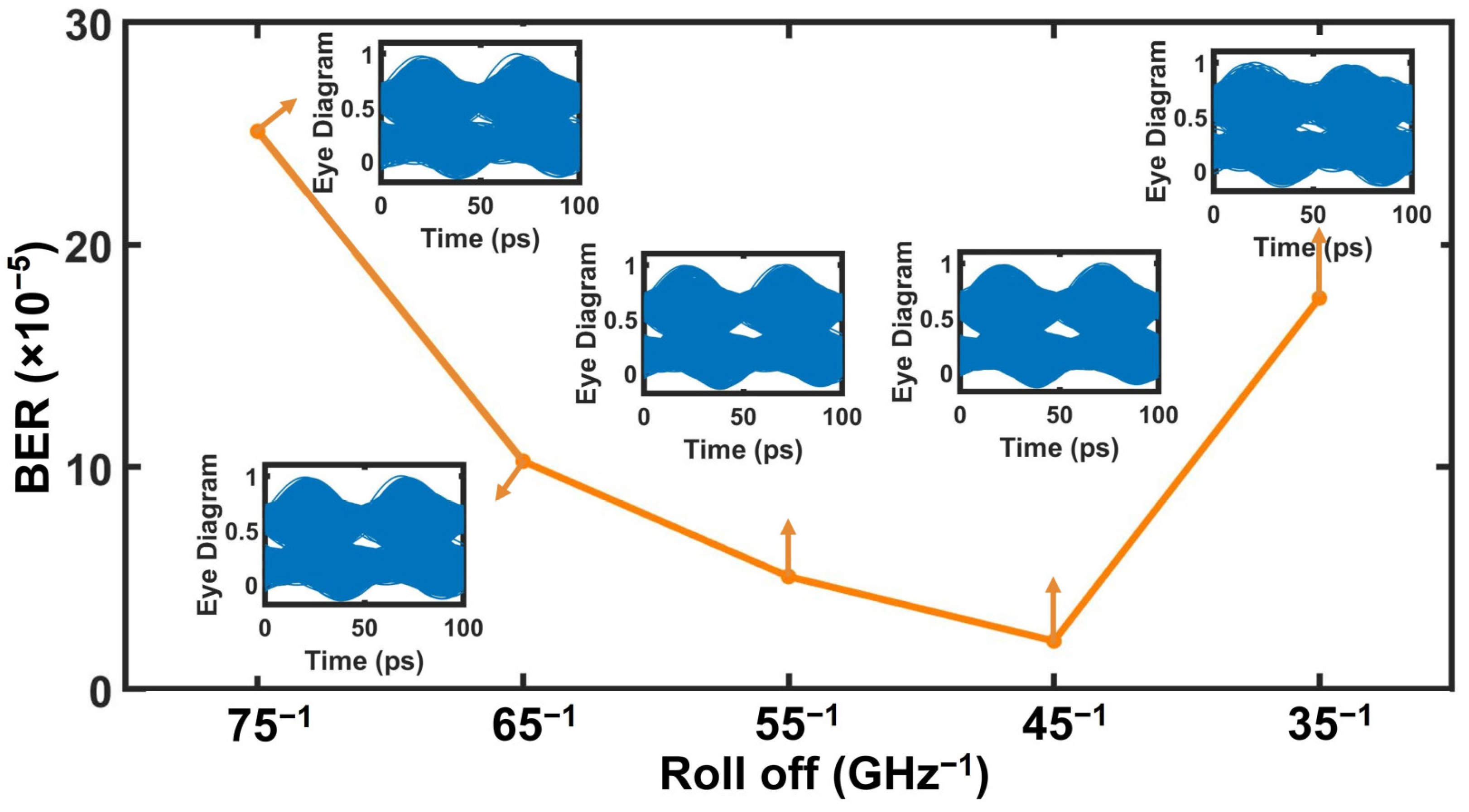
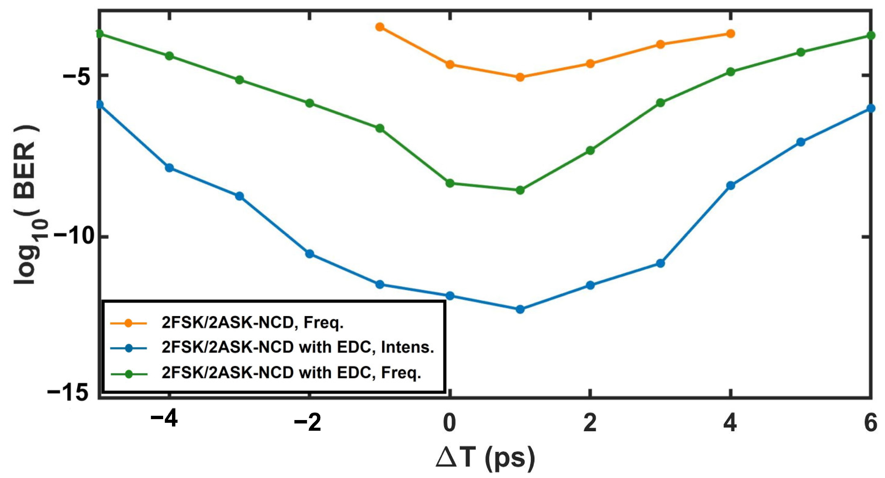
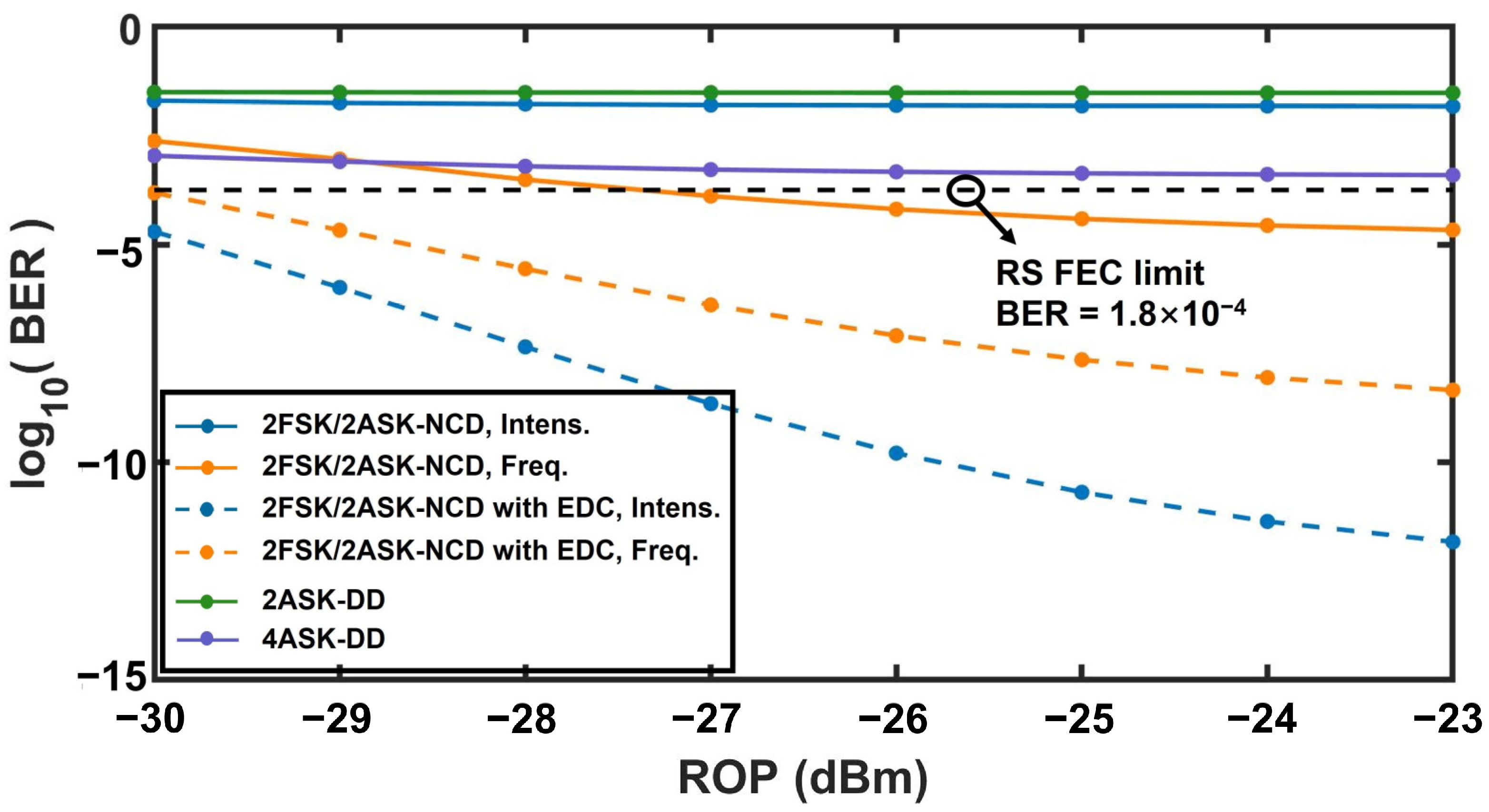
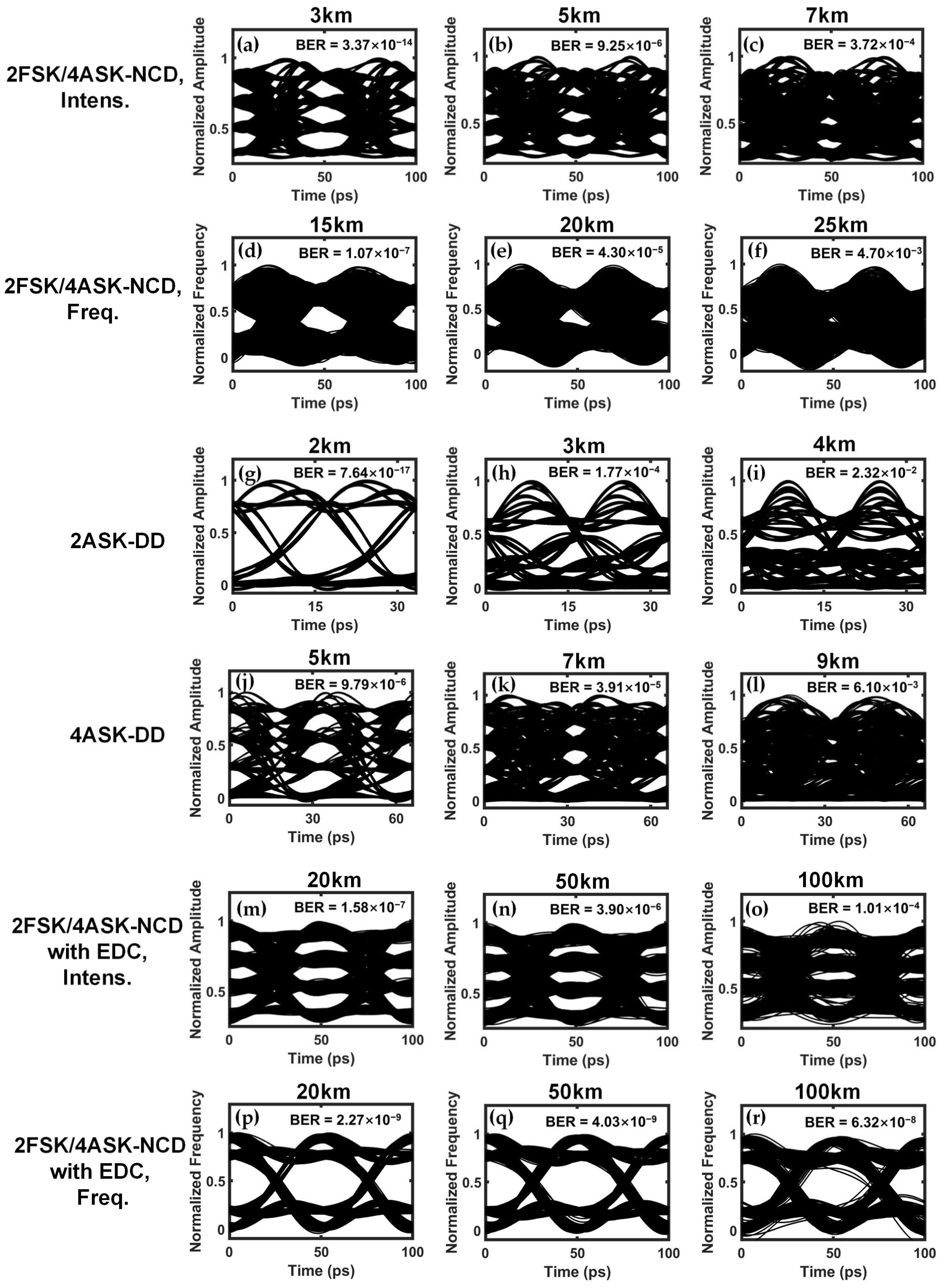
3.1. 2FSK/2ASK Orthogonal Modulation Format

In the transmitter, a 2 12 pseudo-bit sequence as the data signal is initially parallelized using a 1:2 demultiplexer. Subsequently, based on the data signal, impulse shapers generate two sequences of non-return-to-zero (NRZ) rectangle pulses with a bit duration of 50 ps. One sequence of NRZ pulses forms the injection current of the DFB laser, as shown in Figure 2a, modulating the DFB laser directly. The DFB laser is described by a one-dimensional traveling wave model [17,18], whose governing equations are provided in the Supplementary Material and parameters are given in Table 1. As exhibited in Figure 2c, attributed to carrier-induced frequency chirping, the 20 Gbps 2FSK modulation with 5 GHz frequency deviation is achieved. However, IM is generated concurrently, as depicted in Figure 2b. It can be effectively mitigated through the operation of an SOA in its saturation mode, as shown in Figure 2d. Simultaneously, the 2FSK modulation remains relatively unaffected, as depicted in Figure 2e. Consequently, we obtain a rather pure 2FSK optical signal with 5 GHz frequency deviation and 12.3 dBm optical power. The performance of the saturated SOA was evaluated utilizing a physics-based model [17,18,19], which is also given in the Supplementary Material, and its parameters are summarized in Table 2. The other sequence of NRZ pulses forms the driving voltage for the MZM, shown in Figure 2f. This voltage drives the MZM to modulate the amplitude and not affect the frequency of the 2FSK optical signal. Thus, it generates the 40 Gbps 2FSK/2ASK orthogonal modulation optical signal. The intensity of this 2FSK/2ASK optical signal is exhibited in Figure 2g, and the frequency is the same as that of the output 2FSK optical signal from the SOA, given in Figure 2e. In our numerical simulations, we ideally assume the MZM operates at optimal polarization, without considering the impact of polarization.
Afterward, the 2FSK/2ASK optical signal is launched into a G.652 single mode fiber characterized by the loss of 0.2 dB/km and the dispersion of 18 ps/(nm·m) at the wavelength of 1577 nm. The optical wave propagation within the optical fiber is governed by the nonlinear Schrodinger equation [20], which can be efficiently solved using the split-step method [21,22]. Since the proposed system is intended for short-reach communications, the fiber nonlinear effects are negligible. Under this condition, a single iteration in the numerical solver suffices to yield the desired fiber transmission result. Further details regarding optical wave propagation within the optical fiber are provided in the Supplementary Material. In our simulations, the connector loss throughout the fiber link is 2 dB, and the system margin is 3 dB [23].
After fiber transmission, the optical signal is detected by the proposed NCD receiver. In the frequency detection branch, the optical differentiator plays a crucial role of signal conversion from FM to IM. Within the frequency band of the received optical signal, the transfer function of the optical differentiator should be j τ ( ω ω 0 ) in the frequency domain. Practical implementation of this optical differentiator can be achieved through numerous techniques, including long-period fiber gratings [11,24,25,26], phase-shifted fiber Bragg gratings [27,28], interferometers [29,30], silicon microring resonators [31,32], and directional couplers [33,34,35]. Under the condition that the received 40 Gbps FSK/ASK optical signal has an average power of −23 dBm after 10 km fiber transmission, the optical signal after the optical differentiator with a roll-off of 45−1 GHz−1 is presented in Figure 3a, with its intensity containing both encoded intensity and frequency information. The intensity of the optical signal after the optical differentiator in the frequency detection branch, and the intensity of the optical signal in the intensity detection branch, are detected by two separate PDs, respectively, yielding the photocurrents represented as I P D = R P i n + i T t . Here, P i n indicates the input optical power of the PD. The current fluctuation related to thermal noise denoted as i T ( t ) is modeled as a stationary Gaussian random process with the standard deviation of 1 μ A . The current fluctuation related to shot noise is neglected, since thermal noise dominates PIN receiver performance. In our simulation, we choose the responsivity R of both PDs to be 0.9 A/W. Then, electrical noise in both branches is further suppressed by two distinct electrical 6th Butterworth low-pass filters with cut-off frequency B e l of 0.8 × symbol rate. After passing through the electrical low-pass filter, the intensity information of the 2FSK/2ASK optical signal is demodulated in the intensity detection branch, as illustrated in Figure 3b,c. Eventually, following the frequency extraction operation detailed in Equation (4), the frequency information of the 2FSK/2ASK optical signal is demodulated, as shown in Figure 3d,e. Consequently, through the collaboration between the intensity and frequency detection branches, the NCD receiver enables the detection of the FSK/ASK optical signal. Furthermore, thanks to the precise detection of intensity and frequency information, EDC is available in our proposed NCD scheme, leading to a significant improvement in system performance, as evidenced in Figure 3f–i.
We studied the impact of the different roll-offs of optical differentiators on the performances of the proposed FSK/ASK-NCD system, while the average received power is −23 dBm after 20 km fiber transmission. The obtained bit error rate (BER) and eye diagrams in the frequency detection branch with respect to the different roll-off of optical differentiators are shown in Figure 4. We can see that the optimum roll-off is 45−1 GHz−1. This is understandable as an optical differentiator with a faster rolling slope corresponds to a higher average output optical power. This facilitates a substantial improvement in the signal-to-noise ratio (SNR) and consequently yields a reduced BER. At the same time, the roll-off of the optical differentiator should guarantee that the linear region of the transfer function encompasses the frequency band of the received 2FSK/2ASK optical signal with a bit rate of 40 Gbps and frequency deviation of 5 GHz. Otherwise, the fidelity of the detected signal will be jeopardized.
As depicted in Figure 1b and Equation (4), it becomes evident that the successful detection of frequency information through the FE module in the frequency detection branch necessitates collaboration with the amplitude signal detected by the intensity detection branch. Hence, synchronization between the two input signals of the FE module is crucial, otherwise, residual amplitude information could affect the quality of the detected frequency information. Figure 5 illustrates the impact of the asynchrony on the performance of the FSK/ASK-NCD system employing the optimal optical differentiator. Here, T represents the time by which the amplitude signal leads ( T < 0 ) or lags ( T > 0 ). From Figure 5, it can be seen that the optimal system performance occurs not at T = 0 , but at T 1   p s , indicating a lag of approximately 1 ps in the amplitude signal before the FE module. The introduction of the optical differentiator causes a delay in the frequency information relative to the amplitude signal. Therefore, complete synchronization requires a delay in the amplitude signal. In our numerical simulation, the time delay induced by the optical differentiator is introduced through its transfer function j τ ( ω ω 0 ) . In reality, this time delay depends on factors such as device design, the refractive index of the medium, and so on. Furthermore, From Figure 5, it is obvious that as the degree of asynchrony increases, the system performance gradually deteriorates.
With the optimum optical differentiator, we also studied the relationship between the BER and the received optical power (ROP), as depicted in Figure 6, under the condition that the 40 Gbps modulated optical signal transmits for 20 km. A BER threshold of 1.8 × 10⁻⁴ was assumed, because it would yield an output BER of 10−12 for Reed–Solomon (RS) forward error correction (FEC) [36], which is adopted in passive optical networks [37,38]. For the proposed 2FSK/2ASK-NCD system, the BER curve of the detected intensity signal in the intensity detection branch is depicted by a blue solid line. It can be observed that the BER exhibits minimal variation with the ROP and remains higher than the RS FEC threshold, indicating that the 20 km transmission is unattainable for the amplitude signal in 2FSK/2ASK due to the dispersion limitation. The BER curve of the detected frequency signal in the frequency detection branch is depicted by an orange solid line. It demonstrates that when the ROP exceeds −28 dBm, a 20 km transmission for the frequency signal in FSK/ASK is achievable. Obviously, the frequency modulation of the 2FSK/2ASK optical signal shows a superior performance compared to the amplitude modulation. This superiority can be explained as follows: The degradation of the detected amplitude signal induced by optical fiber dispersion is related to the overall bandwidth of the FSK/ASK optical signal. Conversely, for the detected frequency signal, the narrower bandwidth of the optical signal after the optical differentiator effectively suppresses the impact of fiber dispersion, thereby reducing the degradation of the detected frequency signal. Thanks to the demodulation of both the intensity and frequency (or phase) information, EDC is applicable in the proposed NCD. The dashed blue and orange lines represent the BER curves of the demodulated amplitude and frequency information after EDC, respectively. Significant performance improvement can be observed, and a 20 km transmission is allowable for the FSK/ASK optical signal assisted by EDC. For the purpose of comparative analysis, we have also conducted simulations to assess the performance of both the conventional 2ASK-DD system and the 4ASK-DD system with their BER curves depicted by solid green and purple lines, respectively, revealing that their maximum achievable spans do not exceed 20 km. This result is consistent with the research findings in reference [39].
Further insights regarding the maximum achievable spans of systems with a transmission speed of 40 Gbps can be obtained from eye diagrams and BERs shown in Figure 7. The received optical power is −23 dBm. Taking RS FEC limitation of 1.8 × 10⁻⁴ as the threshold, for the proposed 2FSK/2ASK-NCD system, Figure 7a–f reveal that no more than 15 km and 20 km transmission spans are achievable for the ASK and FSK modulation, respectively. The performance of our proposed system surpasses that of the conventional 2ASK-DD system, which exhibits the poorest system performance with the achievable span limited to 6 km, as presented in Figure 7g–i. This poor performance is attributed to the broader bandwidth of the 2ASK optical signal at the same bit rate, resulting in the severe impact of fiber dispersion. Figure 7j–l indicate that no more than a 20 km transmission span is allowable in the 4ASK-DD system, which exhibits system performance comparable to that of our proposed system. Notably, a crucial advantage of the proposed system lies in the enabling of EDC. Assisted by EDC, the proposed 2FSK/2ASK-NCD system exhibits an impressive maximum transmission span of 130 km for 40 Gbps optical signals, as evidenced by eye diagrams in Figure 7m–r. This maximum transmission span far surpasses those of both the 2ASK-DD system and the 4ASK-DD system. However, as observed in Figure 7m–r, EDC in the NCD receiver is not capable of counteracting the impact of fiber dispersion completely. This limitation arises from inherent noise in the PD and the finite bandwidth of the electrical low-pass filter. But, a 130 km transmission span is more than sufficient for short-reach networks. Furthermore, this transmission span indicates the potential of the proposed FSK/ASK-NCD system, augmented by EDC, as a promising technology for future passive optical networks.

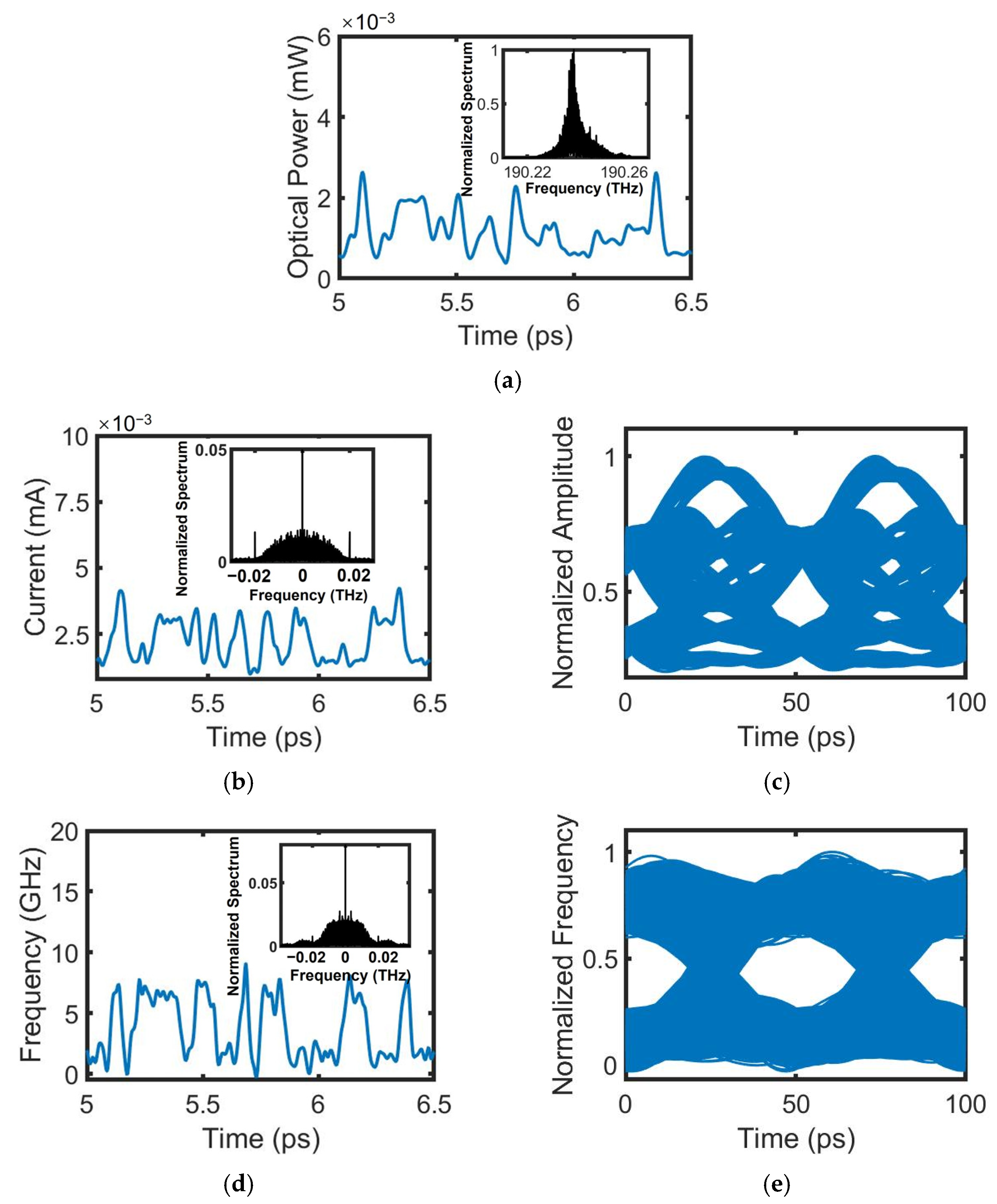
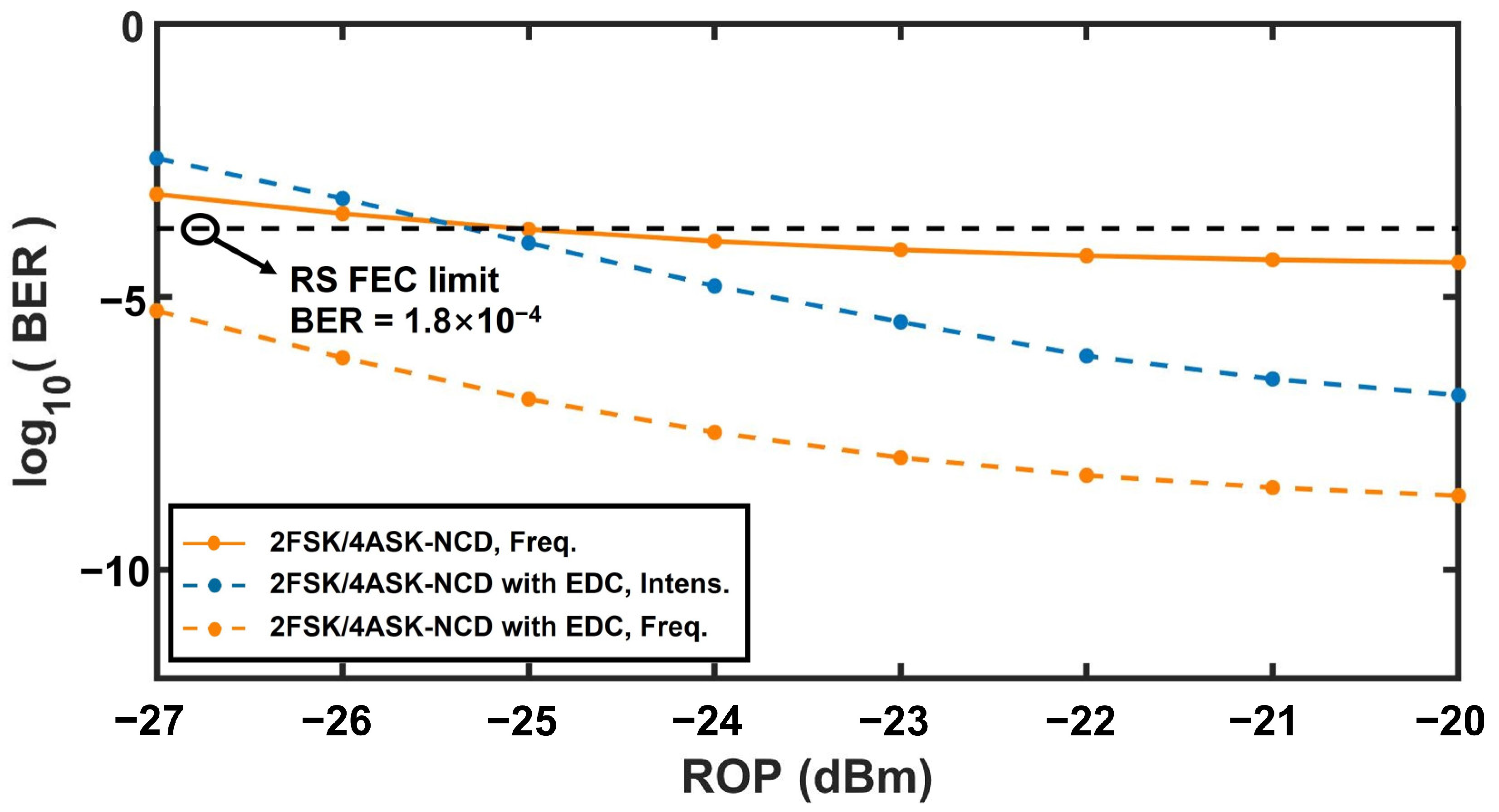
3.2. 2FSK/4ASK Orthogonal Modulation Format

We have also simulated the proposed system in 2FSK/4ASK format with a transmission speed of 60 Gbps, using the system configuration illustrated in Figure 1 along with the simulation models and parameters for functional blocks detailed in Section 3.1. In parallel, simulations were also conducted for the 2ASK-DD system and the 4ASK-DD system under the same condition, serving as the comparison. The result, BER dependence on ROP for the 60 Gbps optical signals after 20 km fiber transmission, is presented in Figure 8. Here, the BER curves of the intensity detection branch in the proposed 2FSK/4ASK-NCD system, the 2ASK-DD system, and the 4ASK-DD system are not depicted, since the optical signals with a bit rate of 40 Gbps transmitting for 20 km are not supported due to the limitation of fiber dispersion, let alone optical signals with a bit rate of 60 Gbps. Figure 8 reveals that, when the ROP is no less than −25 dBm, the frequency signal of the 2FSK/4ASK modulation can achieve direct transmission spans of 20 km in the proposed system. Empowered by EDC, the proposed system allows the 2FSK/4ASK optical signal to transmit over a 20 km span when the ROP exceeds −26 dBm. The resulting eye diagrams with the ROP of −20 dBm are presented in Figure 9. Taking RS FEC limitation of 1.8 × 10⁻⁴ as the threshold, our findings reveal that, in the proposed 2FSK/4ASK-NCD system without EDC, the frequency signal and the amplitude signal achieve direct transmission spans of 20 km and no more than 7 km, respectively. In contrast, the 2ASK-DD system permits the shortest transmission span of only 3 km, and the maximum span for the 4ASK-DD system is approximately 7 km. Notably, augmented by EDC, the proposed 2FSK/4ASK-NCD system exhibits its remarkable capability by enabling a 100 km direct transmission for the bit rate of 60 Gbps. This achievement significantly outperforms both the traditional 2ASK-DD system and the 4ASK-DD system. The superior performance of the proposed FSK/ASK-NCD system underscores its potential for enhancing bitrates in future access networks and establishes it as a strong candidate for future long-reach passive optical networks.

4. Conclusions

We propose the FSK/ASK orthogonal modulation system based on a novel NCD scheme, attempting to enhance the capacity in a cost-efficient manner for short-reach communications. Significantly, compared with the traditional NCD receiver for FSK/ASK systems, the proposed novel NCD receiver overcomes the limitation stemming from the trade-off between the detected signal quality of ASK and FSK modulation. Moreover, the EDC is available. This novel NCD scheme offers a compromise between conventional simple DD, where dispersion cannot be compensated in the electric domain for lack of phase or frequency information, and coherent detection, known for its superior performance but requiring complex phase and polarization tracking. Through comprehensive simulations, the feasibility and effectiveness of the proposed system are demonstrated. With the assistance of EDC, our FSK/ASK-NCD system achieves remarkable results, enabling 100 km transmission for both the 40 Gbps 2FSK/2ASK and the 60 Gbps 2FSK/4ASK optical signals. The performance of our proposed system significantly surpasses that of the 2ASK-DD and 4ASK-DD systems. These superior results indicate that the proposed FSK/ASK-NCD system assisted by EDC is a promising technology for future short-reach optical communications.
In our proposed FSK/ASK-NCD system, we utilize direct current modulation within a DFB laser source to generate FSK optical signals for lower system costs. Consequently, the bit rate of the FSK optical signal, limited by the response of the DFB laser, would impose constraints on the system capacity. Notably, our proposed novel NCD receiver, comprising both intensity and frequency detection branches, remains well suited for the detection of higher-level FSK/ASK orthogonal modulation optical signals. Therefore, to enhance system capacity, direct FSK modulation can be replaced by external FSK modulation, enabling the generation of higher-speed or higher-order FSK optical signals. Of course, this measure, in turn, would increase system costs. Numerous methods have been reported for implementing external FSK modulation, including schemes utilizing a phase modulator under a saw-tooth-like modulation waveform [12], employing a pair of Mach–Zehnder structures based on optical single-sideband modulation techniques [14], utilizing the combination of two demodulated differential phase-shift keying (DPSK) signals [7], or utilizing a specially designed LiNbO3 external FSK modulator [16]. In our future work, we will focus on the FSK/ASK-NCD system based on external FSK modulation, involving higher-speed or higher-level FSK/ASK optical signals.

Supplementary Materials

The following supporting information can be downloaded at: https://www.mdpi.com/article/10.3390/photonics11010044/s1, Section S1: Theoretical model for the DFB laser. Section S2: Theoretical model for the SOA. Section S3: Theoretical model for the optical fiber. References [40,41,42,43,44] are cited in the Supplementary Material.

Author Contributions

Conceptualization, L.X.; methodology, L.X. and X.X.; software, L.X. and L.D.; validation, L.X.; formal analysis, X.X.; writing—original draft, L.X.; writing—review and editing, X.X., L.D., and J.Z.; supervision, X.X.; funding acquisition, X.X. and J.Z. All authors have read and agreed to the published version of the manuscript.

Funding

National Key Research and Development Program of China (No. 2021YFB2800300); National Natural Science Foundation of China (No. 62105183); and Shandong Provincial Natural Science Foundation (No. ZR2021QF052).

Institutional Review Board Statement

Not applicable.

Informed Consent Statement

Not applicable.

Data Availability Statement

Data are contained within the article and supplementary materials.

Conflicts of Interest

The authors declare no conflicts of interest.

References

  1. Kikuchi, K. Fundamentals of coherent optical fiber communications. J. Lightw. Technol. 2016, 34, 157–179. [Google Scholar] [CrossRef]
  2. D’Ambrosia, J. IEEE P802.3bs Baseline Summary. 2015. Available online: http://www.ieee802.org/3/bs/ (accessed on 15 January 2018).
  3. Rizzelli, G.; Nespola, A.; Straullu, S.; Forghieri, F.; Gaudino, R. Two-Fiber Self-Homodyne Transmission for Short-Reach Coherent Optical Communications. In Proceedings of the 22nd International Conference on Transparent Optical Networks (ICTON), Bari, Italy, 19–23 July 2020. [Google Scholar]
  4. Seimetz, M.; Noelle, M.; Patzak, E. Optical systems with high-order DPSK and star QAM modulation based on interferometric direct detection. J. Lightw. Technol. 2007, 25, 1515–1530. [Google Scholar] [CrossRef]
  5. Che, D.; Hu, Q.; Shieh, W. High-spectral-efficiency Optical Direct Detection Using the Stokes Vector Receiver. In Proceedings of the European Conference on Optical Communication (ECOC), Valencia, Spain, 27 September–1 October 2015. [Google Scholar]
  6. Zhang, L.; Zuo, T.; Mao, Y.; Zhang, Q.; Zhou, E.; Liu, G.N.; Xu, X. Beyond 100-Gb/s transmission over 80-km SMF using direct-detection SSB-DMT at C-Band. J. Lightw. Technol. 2016, 34, 723–729. [Google Scholar] [CrossRef]
  7. He, Z.; Tao, Z.; Hu, F.; Chi, N.; Huang, D. 40 Gb/s CSRZFSK signal generation and transmission labeled with ASK in optical packet networks. Optik 2013, 124, 529–532. [Google Scholar] [CrossRef]
  8. Liu, Y.; Fengguang, L. Realization of FSK/ASK modulation format based on a dual-parallel modulator. Opt. Quant. Electron. 2017, 8, 260. [Google Scholar]
  9. Zhou, R.; Xin, X.; Zhang, Q.; Zhao, K.; Zhao, T.; Yu, C. Study of FSK/IM orthogonal modulation system with optical Manchester-coded payload. Chin. Opt. Lett. 2010, 8, 464–467. [Google Scholar] [CrossRef]
  10. Petermann, K. Laser Diode Modulation and Noise; Kluwer Academic Publishers: Dordrecht, NL, USA, 1991. [Google Scholar]
  11. Slavik, R.; Park, Y.; Kulishov, M.; Morandotti, R.; Azaña, J. Ultrafast all-optical differentiators. Opt. Express 2006, 14, 10699–10707. [Google Scholar] [CrossRef]
  12. Kumar, S.; Deen, M.J. Fiber Optic Communications: Fundamentals and Applications; John Wiley & Sons: Chichester, UK, 2014. [Google Scholar]
  13. Kawanishi, T.; Sakamoto, T.; Miyazaki, T.; Izutsu, M. High-speed optical DQPSK and FSK modulation using integrated Mach–Zehnder interferometers. Opt. Express 2006, 14, 4469–4478. [Google Scholar] [CrossRef]
  14. Kawanishi, T.; Higuma, K.; Fujita, T.; Ichikawa, J.; Sakamoto, T.; Shinada, S.; Izutsu, M. High-speed optical FSK modulator for optical packet labeling. J. Lightw. Technol. 2005, 23, 87–94. [Google Scholar]
  15. Deng, N.; Yang, Y.; Chan, C.-K.; Hung, W.; Chen, L.-K. Intensity modulated labeling and all-optical label swapping on angle modulated optical packets. IEEE Photonics Technol. Lett. 2004, 16, 1218–1230. [Google Scholar] [CrossRef]
  16. Yu, Y.; Mulvihill, G.; O’Duill, S.; O’Dowd, R. Performance implications of wideband lasers for FSK modulation labeling scheme. IEEE Photonics Technol. Lett. 2004, 16, 39–41. [Google Scholar]
  17. Li, X. Optoelectronic Devices: Design, Modeling, and Simulation; Cambridge University Press: Cambridge, UK, 2009. [Google Scholar]
  18. Xin, L.; Zhao, J.; Li, X. Suppression of mode partition noise in FP Laser by frequency modulation non-coherent detection. IEEE Photon. J. 2022, 14, 7201310. [Google Scholar] [CrossRef]
  19. Zuo, C.; Li, X. Polarization-Discriminated RSOA–EAM for Colorless Transmitter in WDM–PON. Appl. Sci. 2020, 10, 9049. [Google Scholar] [CrossRef]
  20. Agrawal, G.P. Nonlinear Fiber Optics, 3rd ed.; Academic Press: New York, NY, USA, 2001. [Google Scholar]
  21. Sinkin, O.V.; Holzlohner, R.; Zweck, J.; Menyuk, C.R. Optimization of the split-step Fourier method in modeling optical fiber communication systems. J. Light Technol. 2003, 1, 61–68. [Google Scholar] [CrossRef]
  22. Hardin, R.H.; Tappert, F.D. Applications of the split step fourier method to the numerical solution of nonlinear and variable coefficient wave equations. SIAM Rev. Chron. 1973, 15, 423. [Google Scholar]
  23. Agrawal, G.P. Fiber Optic Communications Systems, 4th ed.; John Wiley & Sons: New York, NY, USA, 2010. [Google Scholar]
  24. Azaña, J.; Kulishov, M. All-fibre ultrafast optical differentiator based on π phase-shifted long-period grating. Electron. Lett. 2005, 41, 1368–1369. [Google Scholar] [CrossRef]
  25. Kulishov, M.; Azaña, J. Long-period fiber gratings as ultrafast optical differentiators. Opt. Lett. 2005, 30, 2700–2702. [Google Scholar] [CrossRef]
  26. Slavik, R.; Park, Y.; Kulishov, M.; Azaña, J. Terahertz-bandwidth high-order temporal differentiators based on phase-shifted long-period fiber gratings. Opt. Lett. 2009, 34, 3116–3118. [Google Scholar] [CrossRef]
  27. Berger, N.K.; Levit, B.; Fischer, B.; Kulishov, M.; Plant, D.V.; Azaña, J. Temporal differentiation of optical signals using a phase-shifted fiber Bragg grating. Opt. Express 2007, 15, 371–381. [Google Scholar] [CrossRef]
  28. Kulishov, M.; Azaña, J. Design of high-order all-optical temporal differentiators based on multiple-phase-shifted fiber Bragg gratings. Opt. Express 2007, 15, 6152–6166. [Google Scholar] [CrossRef]
  29. Park, Y.; Azaña, J.; Slavik, R. Ultrafast all-optical first- and higher-order differentiators based on interferometers. Opt. Lett. 2007, 32, 710–712. [Google Scholar] [CrossRef] [PubMed]
  30. Dong, J.; Zheng, A.; Gao, D.; Lei, L.; Huang, D.; Zhang, X. Compact, flexible and versatile photonic differentiator using silicon Mach-Zehnder interferometers. Opt. Express 2013, 21, 7014–7024. [Google Scholar] [CrossRef] [PubMed]
  31. Liu, F.; Wang, T.; Qiang, L.; Ye, T.; Zhang, Z.; Qiu, M.; Su, Y. Compact optical temporal differentiator based on silicon microring resonator. Opt. Express 2008, 16, 15880–15886. [Google Scholar] [CrossRef] [PubMed]
  32. Dong, J.; Zheng, A.; Gao, D.; Liao, S.; Lei, L.; Huang, D.; Zhang, X. High-order photonic differentiator employing on-chip cascaded microring resonators. Opt. Lett. 2013, 38, 628–630. [Google Scholar] [CrossRef] [PubMed]
  33. Li, M.; Jeong, H.-S.; Azaña, J.; Ahn, T.J. 25-terahertz-bandwidth all-optical temporal differentiator. Opt. Express 2012, 20, 28273–28280. [Google Scholar] [CrossRef] [PubMed]
  34. Ahn, T.-J.; Azaña, J. Wavelength-selective directional couplers as ultrafast optical differentiators. Opt. Express 2011, 19, 7625–7632. [Google Scholar] [CrossRef]
  35. You, H.; Ning, T.; Jian, W.; Pei, L.; Wen, X.; Li, J.; Chen, H. Optical temporal differentiator using a twin-core fiber. Opt. Eng. 2013, 52, 015005. [Google Scholar] [CrossRef]
  36. ITUT, G. Sup39; Optical System Design and Engineering Considerations. International Telecommunication Union: Geneve, Switzerland, 2016.
  37. ITUT, G.9807.1; 40-Gigabit-Capable Passive Optical Networks (NG-PON2): General Requirements 10-Gigabit-Capable Symmetric Passive Optical Network (XGS-PON). International Telecommunication Union: Geneve, Switzerland, 2016.
  38. IEEE 802.3ah; Part 3: Carrier Sense Multiple Access with Collision Detection (CSMA/CD) Access Method and Physical Layer Specifications. Institute of Electrical and Electronics Engineers: New York, NY, USA, 2004.
  39. Azcoaga, B.; Juan, A. 40 Gb/s Optical Transmission Systems. DTU Library. 2003. Available online: https://backend.orbit.dtu.dk/ws/portalfiles/portal/3013571/headb5.pdf (accessed on 28 October 2003).
  40. Jones, D.J.; Zhang, L.M.; Carroll, J.E.; Marcenac, D.D. Dynamics of monolithic passively mode-locked semiconductor lasers. IEEE J. Quantum Electron. 1995, 31, 1051–1058. [Google Scholar] [CrossRef]
  41. Zhao, J.; Shi, K.; Yu, Y.; Barry, L.P. Theoretical analysis of tunable three-section slotted Fabry-Perot lasers based on time-domain traveling wave model. IEEE J. Sel. Top. Quantum Electron. 2013, 19, 1503108. [Google Scholar]
  42. Park, J.; Li, X.; Huang, W.P. Performance simulation and design optimization of gain-clamped semiconductor optical amplifiers based on distributed Bragg reflectors. IEEE J. Quantum Electron. 2003, 39, 1415–1423. [Google Scholar] [CrossRef]
  43. Connelly, M.J. Wideband semiconductor optical amplifier steady-state numerical model. IEEE J. Quantum Electron. 2001, 37, 439–447. [Google Scholar] [CrossRef]
  44. Park, J.; Li, X.; Huang, W.P. Comparative study of mixed frequency-time-domain models of semiconductor laser optical amplifiers. IEE Proc.-Optoelectron. 2005, 152, 151–159. [Google Scholar] [CrossRef]
Figure 1. Schematic representation of (a) the proposed FSK/ASK-NCD system with digital signal processing circuits for (b) frequency extraction (FE) and (c) frequency-domain equalizer (FDE), implementing electronic dispersion compensation (EDC). IS: impulse shaper, DFB: distributed feedback, MZM: Mach–Zehnder modulator, OD: optical differentiator, PD: photodetector, LPF: low-pass filter, ADC: analog-to-digital converter, S/P: serial-to-parallel converter, DFT: discrete Fourier transform, H: the transfer function that equalizes each spectral component, IDFT: inverse DFT, P/S: parallel-to-serial converter.
Photonics 11 00044 g001
Figure 2. Characteristics of the FSK/ASK transmitter: (a) the NRZ signal for FSK modulation, (b) the output optical power of the directly modulated DFB laser, (c) the frequency chirp of the directly modulated DFB laser, (d) the optical power of the output FSK optical signal after saturated SOA, (e) the frequency chirp of the output FSK optical signal after saturated SOA, (f) the NRZ signal for ASK modulation, and (g) the intensity of the output FSK/ASK optical signal from the MZM.
Photonics 11 00044 g002aPhotonics 11 00044 g002b
Figure 3. Characteristics of the NCD receiver: (a) the waveform and spectrum (shown in the inset) of the optical signal after the optical differentiator, (b) the waveform and spectrum (shown in the inset), as well as (c) the eye diagram of the signal after the electrical low-pass filter in the intensity detection branch, (d) the waveform and spectrum (shown in the inset), as well as (e) the eye diagram of the signal after the frequency extraction (FE) module, (f) the waveform and spectrum (shown in the inset), as well as (g) the eye diagram of the intensity signal after electronic dispersion compensation (EDC), (h) the waveform and spectrum (shown in the inset), as well as (i) the eye diagram of the frequency signal after EDC. The received 40 Gbps FSK/ASK optical signal has an average power of −23 dBm after 10 km fiber transmission.
Photonics 11 00044 g003aPhotonics 11 00044 g003b
Figure 4. Dependence of system performance (BER and eye diagrams obtained in the frequency detection branch) on the roll-off of the optical differentiator in the proposed FSK/ASK-NCD system. The received signal power is −23 dBm after 20 km fiber transmission. The FSK signal detected in the frequency detection branch has a bit rate of 20 Gbps.
Photonics 11 00044 g004
Figure 5. Impact of the asynchrony between the two input signals of the frequency extraction (FE) module on the performance of the FSK/ASK-NCD system with the 40 Gbps optical signals transmitting for 20 km. T represents the time by which the amplitude signal, detected in intensity detection branch, leads ( T < 0 ) or lags ( T > 0 ).
Photonics 11 00044 g005
Figure 6. Bit error rate (BER) dependence on the received optical power (ROP) for the proposed 2FSK/2ASK-NCD system with and without the assistance of electronic dispersion compensation (EDC), the 2ASK-DD system, and the 4ASK-DD system, with the 40 Gbps optical signals transmitting for 20 km.
Photonics 11 00044 g006
Figure 7. Eye diagrams of the 40 Gbps optical signal in the proposed 2FSK/2ASK-NCD system after (a) 5 km, (b) 10 km, and (c) 15 km transmission detected in the intensity detection branch, and after (d) 15 km, (e) 20 km, and (f) 25 km transmission detected in the frequency detection branch; eye diagrams in the 2ASK-DD system after (g) 5 km, (h) 6 km, and (i) 7 km transmission; eye diagrams in the 4ASK-DD system after (j) 10 km, (k) 15 km, and (l) 20 km transmission; eye diagrams in the proposed 2FSK/2ASK-NCD system assisted by electronic dispersion compensation (EDC) after (m) 20 km, (n) 100 km, and (o) 130 km transmission detected in the intensity branch, and after (p) 20 km, (q) 100 km, and (r) 130 km transmission detected in the frequency detection branch. The received signal power is −23 dBm.
Photonics 11 00044 g007
Figure 8. Bit error rate (BER) dependence on the received optical power (ROP) for the frequency detection branch of the proposed 2FSK/4ASK-NCD system, as well as the intensity and frequency detection branches in the proposed 2FSK/4ASK-NCD system assisted by electronic dispersion compensation (EDC), with the 60 Gbps optical signal transmitting for 20 km.
Photonics 11 00044 g008
Figure 9. Eye diagrams of the 60 Gbps optical signal in the proposed 2FSK/4ASK-NCD system after (a) 3 km, (b) 5 km, and (c) 7 km transmission detected in the intensity detection branch, and after (d) 15 km, (e) 20 km, and (f) 25 km transmission detected in the frequency detection branch; eye diagrams in the 2ASK-DD system after (g) 2 km, (h) 3 km, and (i) 4 km transmission; eye diagrams in the 4ASK-DD system after (j) 5 km, (k) 7 km, and (l) 9 km transmission; eye diagrams in the proposed 2FSK/4ASK-NCD system assisted by electronic dispersion compensation (EDC) after (m) 20 km, (n) 50 km, and (o) 100 km transmission detected in the intensity branch, and after (p) 20 km, (q) 50 km, and (r) 100 km transmission detected in the frequency detection branch. The received signal power is −23 dBm.
Photonics 11 00044 g009
Table 1. Parameters of the DFB laser.
ParameterSymbolValueUnit
Bragg grating period Λ 248nm
Active region width w 2μm
Total quantum well thickness d 0.04μm
Active region length L 200μm
Optical confinement factor Γ 0.08
Grating coupling coefficient κ 75cm−1
Carrier lifetime τ c 0.1ns
Group index n g 3.6
Material gain coefficient a 2000cm−1
Transparent carrier density N 0 6 × 1017cm−3
Peak gain wavelength λ 0 1577nm
Nonlinear gain suppression coefficient ε 6 × 10⁻¹⁷cm3
Optical modal loss α 15cm−1
Reflectivity of front facet R f 0.3
Reflectivity of back facet R b 0.95
Effective index without injection n e f f 0 3.18
Spontaneous coupling factor γ 1 × 10⁻⁴
Linewidth enhancement factor α L E F 8
IIR filter coefficient η 0.002
Table 2. Parameters of the SOA.
ParameterSymbolValueUnit
Active region width w 2μm
Total quantum well thickness d 0.04μm
Active region length L 200μm
Optical confinement factor Γ 0.08
Carrier lifetime τ c 0.5 *ns
Group index n g 3.6
Material gain coefficient a 2000cm−1
Transparent carrier density N 0 6 × 1017cm−3
Gain profile width λ G 60nm
Peak gain wavelength λ 0 1577nm
Nonlinear gain suppression coefficient ε 6 × 10⁻¹⁷cm3
Optical modal loss α 15cm−1
Reflectivity of front facet R f 0.001
Reflectivity of back facet R b 0.001
Effective index without injection n e f f 0 3.18
Spontaneous coupling factor γ 0.01
Linewidth enhancement factor α L E F 3
Injected current I 100mA
* Requirements of reduced saturation power.
Disclaimer/Publisher’s Note: The statements, opinions and data contained in all publications are solely those of the individual author(s) and contributor(s) and not of MDPI and/or the editor(s). MDPI and/or the editor(s) disclaim responsibility for any injury to people or property resulting from any ideas, methods, instructions or products referred to in the content.

