Article

Theoretical Demonstration of Improved Performance in Multi-Channel Photonic RF Signals Based on Optical Injection Locking of Optical Comb and Array Lasers

Department of Electronic and Electrical Engineering, Hongik University, Seoul 04066, Republic of Korea
*
Author to whom correspondence should be addressed.
Photonics 2024, 11(2), 143; https://doi.org/10.3390/photonics11020143
Submission received: 17 January 2024 / Revised: 30 January 2024 / Accepted: 2 February 2024 / Published: 4 February 2024
(This article belongs to the Special Issue Time and Frequency Transfer over Fiber Link)

Abstract

:
Multi-channel radio frequency (RF) signal generation, facilitated by photonic technology, offers significant potential for generating coherent signals with a high frequency and low phase noise, providing multifunctional capabilities across diverse platforms, including RF and photonic systems. Traditional methods for multi-channel photonic RF signal generation typically entail the integration of diverse optical components, such as filters and amplifiers. However, this integration often results in compromises related to power efficiency, cost-effectiveness, and implementation simplicity. To address these challenges, we propose a novel method for generating multi-channel photonic RF signals based on optical injection locking technology. This approach eliminates the necessity for traditional optical components, leading to a substantial enhancement in the performance of photonic RF signals. We present the design of an optical injection locking-based multi-channel photonic RF signal generation schematic and theoretically evaluate its Signal-to-Noise Ratio (SNR) and eye pattern performance for data modulation using the Lumerical INTERCONNECT simulator. Our results reveal a significant 1.3-dB and 3.6-dB enhancement in SNR for 30-GHz and 60-GHz signals, respectively. Furthermore, we observed an improved communication performance, as evidenced by enhanced eye patterns in 3-Gbps data transmission compared to passive photonic RF signal generation methods.

1. Introduction

Over the past decade, considerable research and development efforts have been devoted to advancing the generation of high-frequency and multi-channel radio frequency (RF) signal to meet the evolving demands of modern RF applications, including wired/wireless communications [1] and radar systems [2]. However, the integration of microwave components into the transmitter and receiver modules of these application systems has introduced challenges, notably high noise and low stability, thereby constraining overall system performance [3,4]. Specifically, the necessity for multiple stages of up- and down-conversions in high-frequency RF systems has resulted in increased phase and amplitude noise [5,6].
In response to these limitations, and with a focus on improving stability, there is a growing interest in the integration of photonics and microwave technology, commonly referred to as microwave or RF photonics. This approach involves the generation of RF carrier signals in the optical domain through the heterodyning of two different-wavelength optical signals at the photodetector [7]. Consequently, RF carrier signals, generated based on microwave photonic technology, cover a broad frequency spectrum, extending up to millimeter and THz waves while maintaining stable phase characteristics. The advantages of employing microwave photonic technology include the elimination of microwave components and multistage up and down-conversions, allowing for the simplification of RF frequency-operating systems and a reduction in their size and cost. Consequently, photonic RF signal generation methods have emerged as prominent candidates for advanced RF applications requiring a high-frequency spectrum, such as radar, communications, and electronic warfare [7,8].
In addition to the demand for high-frequency operation, various research groups have proposed a multi-channel RF signal generation system owing to its advantages over the single-channel system. The advantages include application diversity, adaptability to various environments, enhanced reliability, and the ability to mitigate disruptions caused by RF signal interferences [2]. Owing to the frequency flexibility inherent in photonic RF signal generation, coupled with the aforementioned advantages, multi-channel photonic RF signal generation technology has progressed into the next generation of technology [9]. Photonic RF signal generation exploits optical techniques to generate multiple RF signals on a single-platform hardware based on wavelength division multiplexing [10], tunable optoelectronic oscillator [11], and optical frequency comb [12]. As a result, multi-channel photonic RF signal generation systems offer high-quality signals and a wide range of tunable frequencies with simple implementation [9,13]. Notably, multi-channel photonic RF signal generation holds significant potential for multipurpose systems, facilitating the cooperation of various applications within a single system, such as high data-rate communication, radar systems, and medical imaging.
In this study, we introduce a novel coherent multi-channel RF signal generation based on optical injection locking technology and conduct a comprehensive theoretical performance evaluation. Our approach utilizes a coherent optical frequency comb (OFC) as a master laser (ML) and an array of single-mode semiconductor lasers as slave lasers (SLs). The OFC offers several advantages, including a broad operational bandwidth, high coherence, precise frequency control, low phase noise, and frequency stability, making it suitable for various fields required high-quality coherent signals such as quantum communication [14,15] and particularly multi-channel RF signal generation [16,17].
In contrast to recent work [17], we propose the optical injection of the OFC to an array of SL. The optical injection locking process between the OFC ML and the array of SL achieves the selection and amplification of the target optical frequency from the multiple frequencies of the OFC, while concurrently preserving optical signal coherence. This eliminates the need for optical bandpass filters, consequently removing the requirement for optical amplifiers to compensate for the power loss of the bandpass filter and provide sufficient optical power for RF signal generation. Additionally, for the data modulation stage, we implement direct modulation of the SL without the use of external modulators. Since the SL is locked to one of the OFC modes, the modulation bandwidth of the optically injection locked (OIL) SL can be significantly increased [18,19]. Direct SL modulation also brings benefits such as cost reduction, simplified configuration, and improved power efficiency by eliminating the need for external optical modulators.
Our results demonstrate a 1.3-dB and 3.6-dB improvement in SNR for 30-GHz and 60-GHz RF signals, respectively, compared with those generated by conventional multi-channel photonic RF signal generation method employing optical filters and external modulators, referred to as “passive” multi-channel photonic RF signal generation system in this manuscript. Furthermore, we present enhanced eye patterns at a 3-Gbps data rate, affirming the capability for high-data-rate communication within a single platform. The optical injection locking-based multi-channel photonic RF signal generation system, with its enhanced data modulation performance, holds promise for widespread development, catering not only to multi-channel communication systems but also to multifunctional photonic radars that seamlessly integrate radar, sensing, and communication functions within a single hardware platform. Moreover, the deployment of multi-channel RF signal generation systems offers a substantial improvement over single-channel RF systems by integrating information from multiple RF generated signals. This approach proves instrumental in mitigating degradation caused by interference, environmental noise, and dynamic condition changes. The realized enhancements in SNR and eye-pattern performances play a pivotal role in elevating the accuracy, reliability, quality, and clarity of various applications, such as radar target detection and navigation, communication signals, sensing, and imaging.
Furthermore, the proposed multi-channel RF signal generation system, founded on optical injection locking, introduces compact dimensions, simplicity, and low power consumption in system configuration. This addresses the growing demands across diverse real-world application fields, including but not limited to military, medical, automation, and mobile communication.

2. Principle of Multi-Channel Photonic RF Signal Generation Using OIL Semiconductor Lasers

2.1. Target Mode Selection and Amplification Using Optical Injection Locking Technology

Figure 1 shows the schematic of the optical selection and amplification utilizing optical injection locking technology. Optical injection locking is the technology that synchronizes the phase and frequency of SL output signal with the ML. The synchronization of the phase and frequency of the SL with the ML is achieved through the proper control of two injection locking parameters: the injection ratio and detuning frequency [18,19,20]. The injection ratio represents the power ratio between the ML and SL, and the detuning frequency is the frequency difference between the ML and SL. Experimental control of the injection ratio involves the use of optical power control components, such as optical attenuators and amplifiers, inserted between the ML and SL. The detuning frequency can be manipulated experimentally by varying the optical frequency of the ML or by temperature tuning of the semiconductor SL. Moreover, the simultaneous control of both injection locking parameters is possible by directly modulating the bias current of the SL, as discussed in research [20].
Within the stable locking regime, achieved through precise control of these injection locking parameters, either separately or simultaneously, the phase and frequency of the SL are synchronized with those of the ML. Simultaneously, the OIL semiconductor laser can exhibit high power, even when the injecting ML power level is low, in what is termed the weak injection-locked regime. Consequently, the optical injection locking process in the SL can equivalently function as an optical filter and amplifier, effectively selecting and amplifying a target mode of OFC comb modes without requiring optical bandpass filters and amplifiers, while maintaining signal coherence.
The proposed system for mode selection and amplification, based on optical injection locking technology, comprises an OFC as a ML and a semiconductor laser serving as the SL. The OFC generates a sequence of coherent optical modes equally spaced by Δ f O F C [21]. The frequency of n t h mode can be expressed as:
f n , M L = f 0 + n Δ f O F C ,
where f 0 is the frequency of a reference-selected mode. The complex electrical field of the OFC signal injected into the SL is represented as:
E O F C t = n E M L t e x p j 2 π f n , M L t + ϕ M L   ,
where E M L and ϕ M L denote the field amplitude and initial phase of each OFC mode, assumed to be the same value for all OFC modes. For simplicity, we set the initial phases of OFC modes to 0. The complex electrical field of the SL in a free-running state (i.e., without optical injection) is described as:
E f r e e , S L t = E f r e e , S L t e x p j 2 π f f r e e , S L t + ϕ f r e e , S L t ,
where f f r e e , S L , E f r e e , S L , and ϕ f r e e , S L are the frequency, field amplitude, and initial phase of free-running SL. After injection, the carrier number N t , field amplitude E t , and phase ϕ t of the SL are expressed using the rate equations [19,20,22,23] as:
d N ( t ) d t = J b i a s t γ n N t { γ p + g N t N t h } E t 2 ,
d E t d t = 1 2 g N t N t h E t + κ E M L n c o s 2 π Δ f n t ϕ t ,
d ϕ t d t = 1 2 α { g N t N t h γ p } κ E M L E t n s i n 2 π Δ f n t ϕ t ,
where γ n , γ p , g , N t h , κ , and α denote the carrier recombination rate, photon decay rate, gain coefficient, threshold carrier number, coupling rate and linewidth enhancement factor of the SL, respectively. Δ f n = f n , M L f f r e e , S L and R = E M L 2 / E f r e e , S L 2 represent the detuning frequency and injection ratio between n t h mode of the ML OFC and the free-running SL, respectively. These two injection parameters are typically adjusted to lock the SL exclusively to the target mode among several modes of the OFC.
Figure 2 illustrates a stable locking range as a function of detuning frequency and injection ratio, following Equations (4)–(6). The locking range gradually narrows as the injection ratio reduces. To lock the SL to only one mode of the OFC ML, the free-running frequency of the SL must be adjusted to be very close to the frequency of the target mode, i.e., the detuning frequency value should be close to 0. Our proposed system necessitates single-mode selection, requiring the SL to be locked to only one target mode of the OFC. To avoid multi-mode locking and ensure precise locking to the target mode [19], it is essential for the locking range to be narrower than the comb mode spacing Δ f O F C . For achieving single-mode locking, we adjust the free-running frequency of the SL to be very close to the target mode, corresponding to a low regime of injection ratio, as depicted in Figure 2. The maximum injection ratio under which the system remains stable can be determined by the value of Δ f O F C , as illustrated in Figure 2.
Furthermore, since a high-power SL is used in the proposed system, the power of the OFC ML does not need to be high. A low power level in the OFC ML also ensures the energy efficiency, reliability, cost-effectiveness, and simplicity of the OFC, serving as the primary optical source in the photonic RF signal generation system.

2.2. Multi-Channel RF Signal Generation Using OIL-Laser-Based System

Due to the mode selection and amplification ability of OIL lasers, we propose a conceptual configuration of a multi-channel photonic RF signal generation method utilizing OIL semiconductor lasers, as demonstrated in Figure 3a. The OIL-based multi-channel photonic RF signal generation system consists of two sections: optical and electrical. In the optical section, an OFC generates a set of in-phase and equally spaced optical frequencies that are injected into an array of semiconductor SLs. Through bias current adjustment on each SL, the optical injection locking parameters are manipulated to fulfill the injection-locking conditions. This process synchronizes the SL outputs with the frequency of the target optical modes within the OFC. Consequently, the desired optical signals are filtered from the spectrum of OFC and amplified to achieve sufficient power while maintaining robust coherence and stability. This is attributed to the inherent coherence property of OFC signals and the high stability of OIL output signals. In the electrical domain, multiple RF signals are simultaneously generated with frequencies matching the differences between the filtered optical signals beaten in the photodetector. RF filters are then employed to select the target radar bands for various advanced RF applications such as sensing, radar, and communication. For data transmission or pulse generation purposes, the OIL-based multi-channel photonic RF signal generation system can employ external or direct modulation on one of the selected optical modes. Direct modulation of OIL lasers offers advantages such as noise reduction and system simplification, achieved by elimination of external components [20].
Figure 3b presents the qualitative pictures depicting the principle of the OIL-based multi-channel photonic RF signal generation. The generation of multi-channel RF signals starts from the OFC spectrum, which consists of a series of coherent optical modes, equally spaced by Δ f O F C [21]. The frequency of n t h mode can be expressed in Equation (1). To generate two RF signals simultaneously, three target optical modes should be selected with their frequencies selected as f 0 , f N = f 0 + N Δ f O F C , f M = f 0 + M Δ f O F C . Data is directly embedded to one of the selected modes, for example f 0 mode, by adding the data signal to bias current of SL using bias tee device. Three above optical modes are heterodyned at the photodetector, then several of beatings are generated. By using RF filters, the two target RF signals with the frequencies of f R F 1 = N Δ f O F C and f R F 2 = M Δ f O F C , carrying the communication information, are selected for transmission via RF antennas for radar systems or wireless communications.

3. Performance Evaluation and Comparative Analysis of Multi-Channel Photonic RF Signals: Passive vs. OIL-Based Approaches

In this section, we evaluate the performance of multi-channel photonic RF signals generated by our proposed OIL-based method, comparing it with signals produced by the conventional passive photonic generation approach. The assessment involves comprehensive simulations conducted using the Lumerical INTERCONNECT simulator, a commercially available software explicitly designed for simulating photonic integrated circuits and subsystems. We chose this simulation approach based on the conviction that it provides a more intuitive and flexible method for system design when compared to the combination of equation-based simulation results from individual components and configuration sections. The simulation schematics, illustrating the assessment of both the passive multi-channel photonic RF signals and the proposed OIL-based multi-channel photonic RF signals, are depicted in Figure 4a and Figure 4b, respectively.
Initiating our study, we construct the conventional passive multi-channel photonic RF signal generation configuration, wherein the optical section comprises optical components, including optical bandpass filters and amplifiers, as depicted in Figure 4a [19]. Subsequently, we construct our proposed OIL-based multi-channel photonic RF signal generation configuration, as shown in 
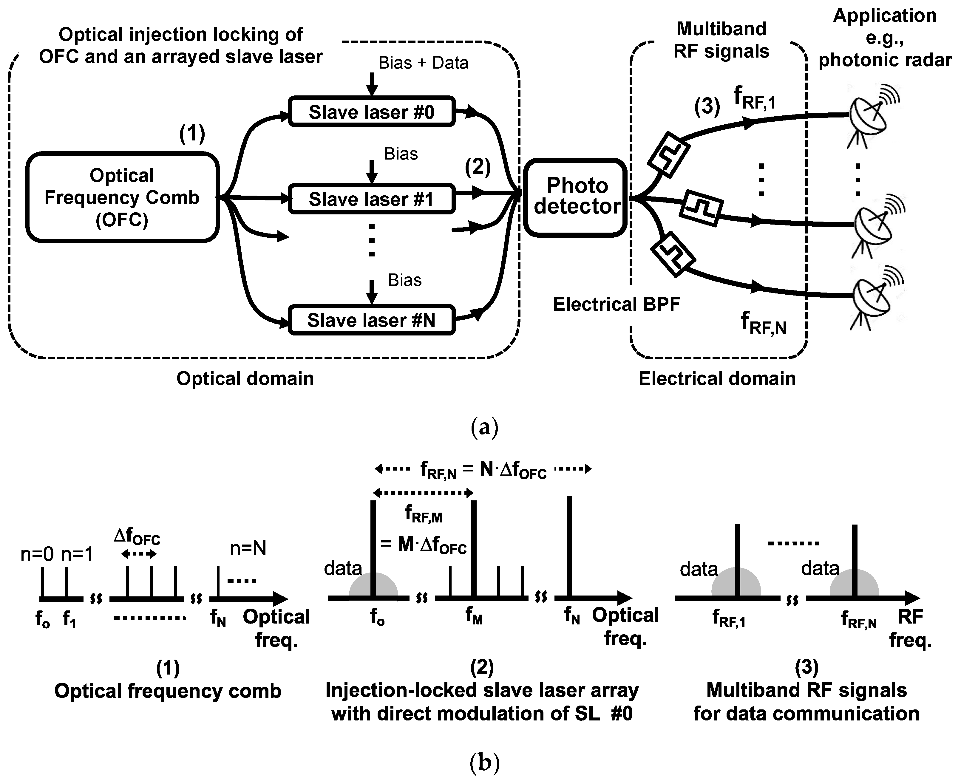
Figure 4b, and proceed to compare their respective performances. Both configurations are assembled using built-in elements from the Element Library of the Lumerical INTERCONNECT simulator.
For the passive multi-channel photonic RF signal generation, the OFC is designed from an array of eleven in-phase continuous wave lasers [24]. Notably, one of the optical comb modes is modulated in an external optical modulator to carry information data. The three selected and amplified optical modes are heterodyned at the photodetector to generate dual-channel RF signals. These signals undergo filtering by electrical bandpass Chebyshev filters to realize the desired RF signals with the modulated data. Various optical and electrical analyzers, such as an oscilloscope, spectrum analyzer, carrier analyzer, and eye diagram from the Element Library, enable the analysis of system performance in both time and frequency domains.
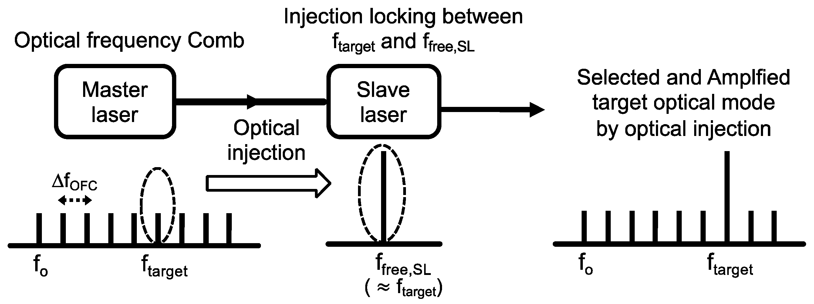
For the OIL-based multi-channel photonic RF signal generation, the same OFC is employed as in the passive system, with the OFC serving as the master laser and three traveling wave lasers (TWLs) functioning as slave lasers (SLs). Optical circulators facilitate optical injection between the OFC modes and the SLs, resulting in the selection and amplification of the target modes, as illustrated in Figure 1. The power and lasing frequency of the SLs are controlled by direct current (DC) sources, providing DC bias currents for TWLs. Importantly, one of the TWLs in the SL array is directly modulated by the data, offering a simpler and more cost-effective configuration than the external modulation case. This is owing to the enhanced modulation performance achievable by the OIL laser [18,19]. The remaining components are identical to those described in the passive multi-channel photonic RF signal generation schematic, with each component’s properties appropriately configured to ensure effective system operation, facilitating the generation of multiple RF signals and transmitting information data.
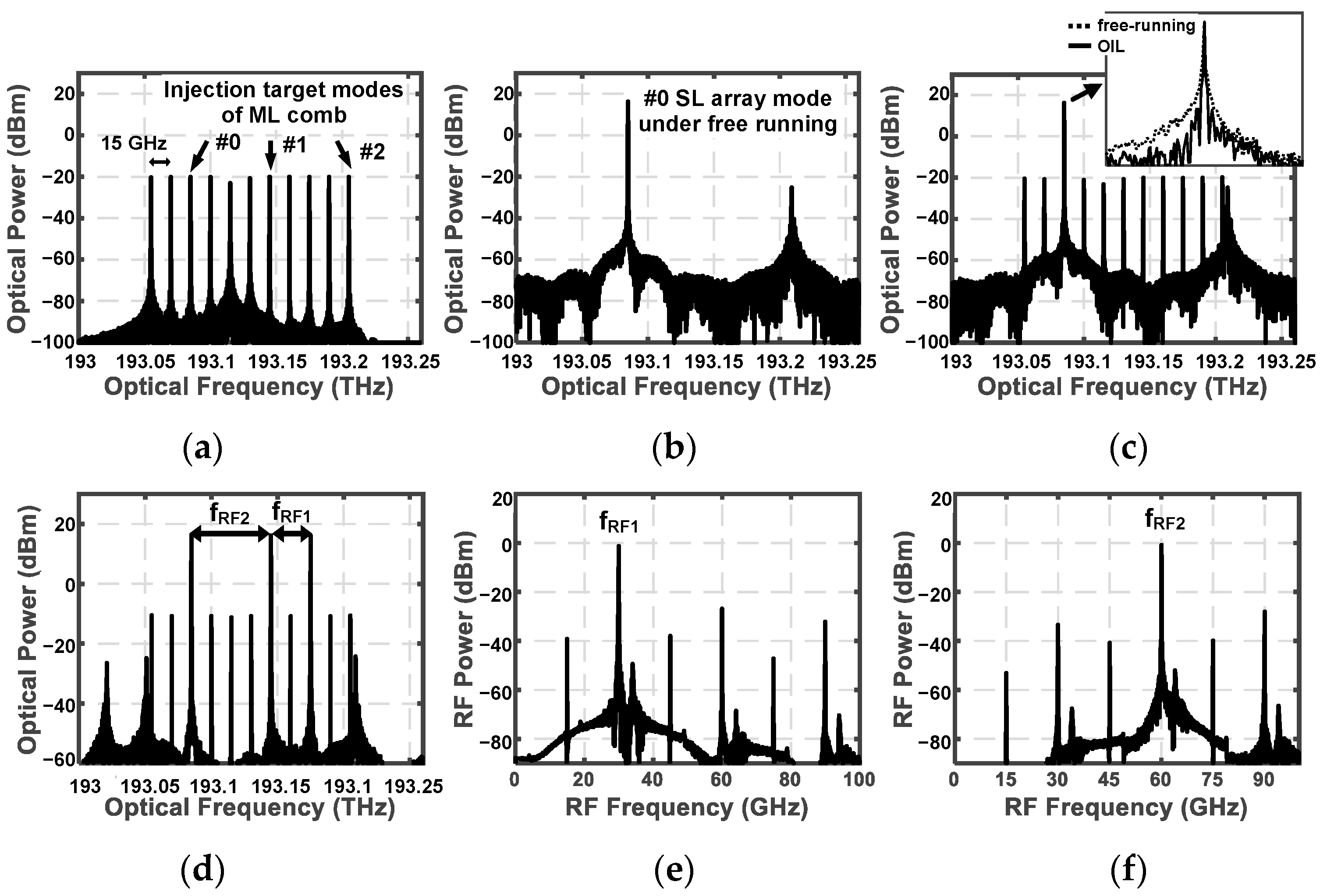
Figure 5 illustrates the optical and RF spectra, elucidating the evolution of optical and RF signals leading to the generation of dual-channel RF signals using the OIL-based multi-channel photonic RF signal generation system, as depicted in Figure 4b. The intended frequencies for the dual-channel signals are 30 GHz and 60 GHz, respectively. We generate an OFC with a sequence of 11 coherent optical modes having a frequency spacing of Δ f O F C = 15 GHz as shown in Figure 5a. Among these 11 coherent optical modes, we specifically identify three modes as #0, #1, and #2 modes, as depicted in Figure 5a. These modes are designated as the target injection modes of the ML comb and serve as master laser modes to lock the corresponding three modes of the SL array. The optical power of each OFC mode is set to 20 dBm to achieve a low injection ratio. This low injection ratio facilitates a narrow locking range, allowing for precise selection and amplification of the target mode without interference from untargeted comb modes and the SL array mode.
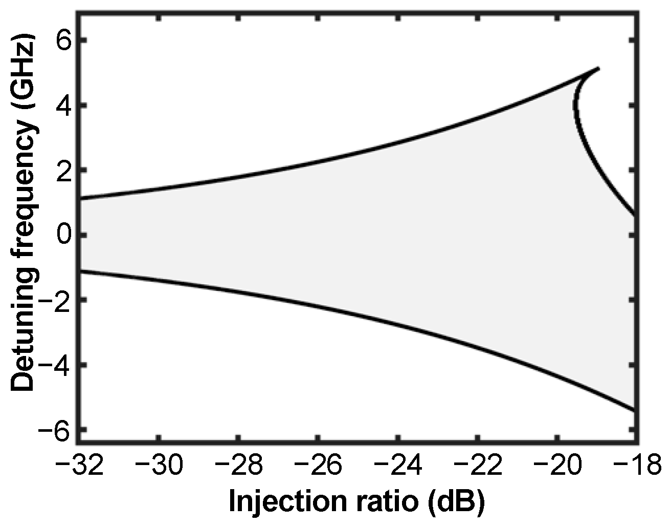
In our simulation, we drive the SLs with relatively high DC bias currents, achieving approximately 16.5 dBm of high output powers, which results in a low injection ratio of 36.5 dB. Due to the low injection ratio, injection locking phenomena occur when the frequency difference between the ML and free-running SL approaches nearly zero, as explained in Figure 2. We set the frequencies of the TWLs, which are SLs, identical to the frequencies of the three target modes: 193.085 THz, 193.145 THz, and 193.175 THz, respectively. This configuration ensures zero detuning frequencies to lock the SLs to the target modes.
Figure 5b,c depict the spectra of one of the SL arrays in free-running and OIL cases, respectively. The optical frequency is 193.085 THz for free-running cases, corresponding to the #0 target frequency. Injection locking between the #0 comb mode and #0 SL array mode selectively amplifies the #0 target mode without losing phase coherence (Figure 5c). The inset in Figure 5c illustrates the locked SL spectrum, demonstrating a significantly narrower linewidth compared to the free-running SL.
Similarly, the remaining two target modes (#1 and #2) of the ML OFC as shown in Figure 5a undergo filtering and amplification facilitated by the optical injection locking of the ML OFC and the SL array modes. To maintain conciseness, the corresponding optical spectra for these processes are not individually presented in separate figures. The target modes #1 and #2 experience an approximate 36 dB amplification compared to the 20 dBm power level for each OFC mode while preserving low noise floor performance through the OIL process. The optical signals are combined through an optical coupler, and Figure 5d displays this combined optical spectrum, exhibiting the three amplified modes selected by the locking process. This optical signal is then delivered to a photodetector for dual-channel RF signal generation. The photodetector mixes the optical modes and generates beat notes corresponding to the mode spacing. The generated dual-channel RF signals are filtered by the two electrical bandpass Chebyshev filters with center frequencies of 30 GHz and 60 GHz, respectively. The filter bandwidth is designed at 2.25 GHz, corresponding to 0.75 times the 3-Gbps data rate, allowing for a reasonably high data rate while ensuring acceptable reliability in data transmission [25]. We will demonstrate data modulation at 3 Gbps using the proposed OIL-based dual-channel photonic RF signal carrier in subsequent simulations. Figure 5e,f depict the RF signals of 30 GHz and 60 GHz, respectively, tapped after the electrical bandpass filters. Although side modes are present due to signal mixing in the photodetector, the side mode suppression of 36 dB are still low enough not to impact the majority of the optical and/or RF system performance that utilizes the dual-channel signal. This will be demonstrated through the analysis of data modulation results.
We proceed to assess the performance of RF signals generated by our proposed multi-channel photonic RF signal generation configuration. Subsequently, we compare these results with those obtained using a passive photonic RF signal generation configuration. The simulation for passive photonic RF signal generation is executed utilizing the schematic illustrated in Figure 4a. To ensure a fair comparison of signal performance generated by the passive photonic RF signal generation configuration with the OIL-based photonic RF signal generation, we employ an optical filter with the narrowest bandwidth commercially available, set at 0.1 nm. Specifically, the TFN Narrowband Tunable Optical Filter by Teraxion is utilized to maintain consistency with the OIL-based multi-channel photonic RF signal generation system. Optical amplifiers with a 40-dB gain are applied after the optical filters to achieve 16-dBm powers for the selected modes, mirroring the power levels of the OIL-based multi-channel photonic RF signal generation system. These optical amplifiers incorporate a noise figure of 7.5 dB, derived from a commercial amplifier (C-Band booster and semiconductor optical amplifiers from Thorlabs). Consequently, an increased noise floor is anticipated in the optical spectrum due to amplification.
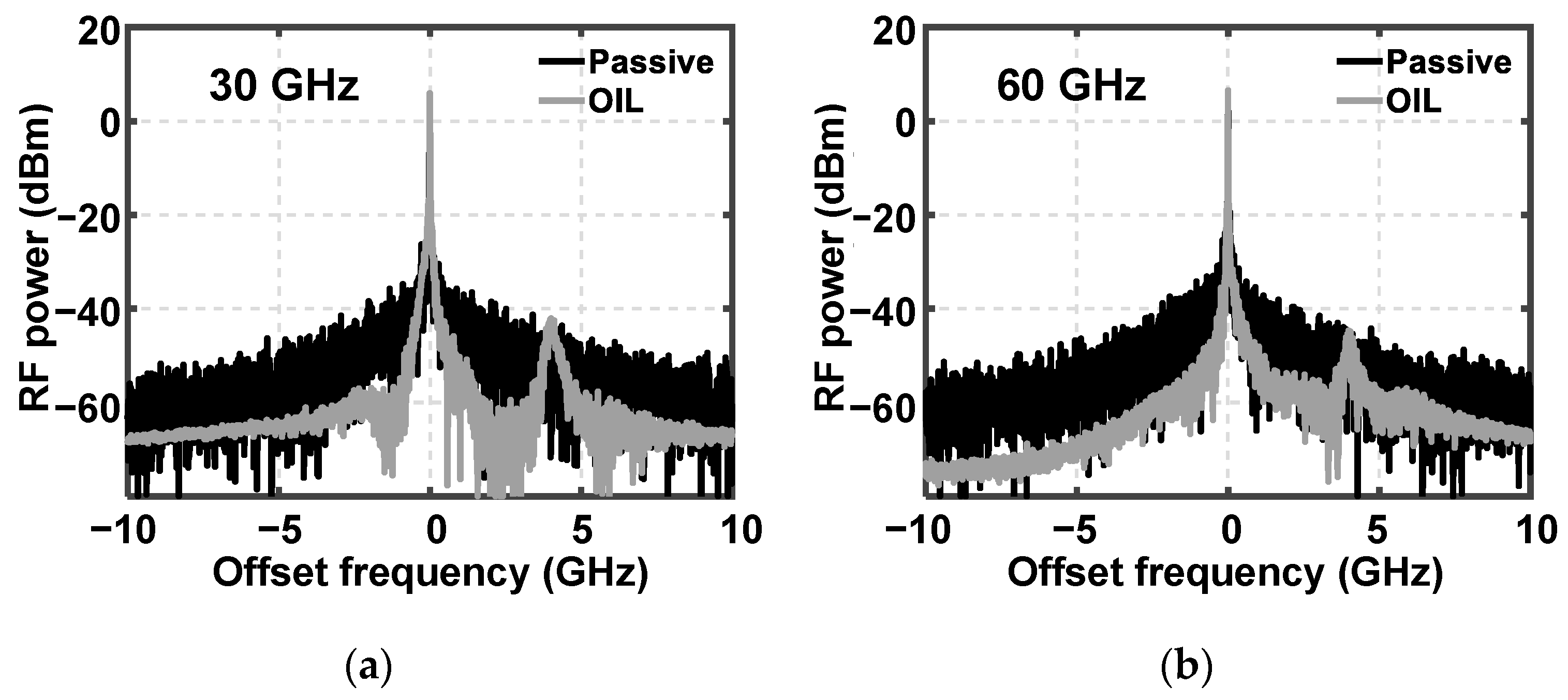
Figure 6a,b illustrate the spectrum of dual-channel RF signals generated by both the passive and OIL-based photonic RF signal generation configurations for 30-GHz and 60-GHz RF signals, respectively. The multi-channel photonic RF signals, produced using the proposed OIL system, demonstrates a significant noise reduction and an improved SNR of 1.3 dB and 3.6 dB at 30-GHz and 60-GHz signals, respectively. The SNR values are obtained through the carrier analyzer element included in the Element Library of the Lumerical INTERCONNECT simulator. This improvement is attributed to the absence of amplifier-induced noise within the simulation scope. In practical experiments, the passive multi-channel photonic RF signal generation system may experience a degradation in signal performance due to additional loss and noise introduced by various components, including optical filters and connectors. Remarkably, relying exclusively on active devices, specifically employing optical injection locking of OFC and an array of TWL for signal selection and amplification, not only delivers superior performance but also offers cost-effectiveness, increased energy efficiency, and system simplicity for multi-channel photonic RF signal generation.
Subsequently, we conducted a simulation on data modulation performance using the dual-channel photonic RF signals as carriers. Specifically, instead of modulating the RF carriers in the RF domain, we modulate the optical signal to leverage the benefits of optical modulation. In this simulation, we introduce data modulation to the 193.145-THz optical mode for both photonic RF signal generation systems. This analysis aims to assess the feasibility of data transmission and enables a comprehensive comparison between the passive and the OIL-based methods. In the passive multi-channel photonic RF signal generation system, an external amplitude modulator is employed after an optical amplifier, as illustrated in Figure 4a. Conversely, in our proposed system utilizing OIL lasers, communication data is embedded into the 193.145-THz optical mode through direct modulation of the bias current on the TWL, as depicted in Figure 4b. The pseudo-random bit sequence generator generates a 3-Gbps non-return-to-zero pulse for data transmission.
In our eye pattern analysis, we employ the Eye Diagram tool from the Element Library. Figure 7a,b present the eye patterns of 3-Gbps non-return-to-zero pulses for 30-GHz RF carriers, illustrating the transmitter signal quality through external modulation of a passive multi-channel photonic RF system and direct modulation of an OIL-based multi-channel photonic RF system, respectively. The passive multi-channel photonic RF signal generation system exhibits a narrowed opening of the eye pattern, attributed to amplified noise resulting from the use of optical amplifiers to compensate for signal loss caused by passive optical components including optical bandpass filters and optical modulators. On the other hand, the OIL-based multi-channel photonic RF signal generation system demonstrates a significantly broader eye-opening diagram, as shown in Figure 7b. The similarity in the width of the eye-opening in the modulated signal at 60-GHz RF signals for both passive multi-channel photonic RF signal generation (Figure 7c) and the OIL-based case (Figure 7d) confirms the superior performance of direct modulation in the OIL-based multi-channel photonic RF signal generation system.
The improved eye opening in the OIL-based system is attributed to the enhanced modulation performance of OIL lasers [18,19] and the combined impact of mode selection and amplification achieved through the injection locking between an OFC and a SL array for multi-channel RF signal generation. Significantly, this system eliminates the need for external optical components, including optical filters, modulators, and amplifiers. This not only efficiently reduces associated noise levels but also facilitates a cost-effective system configuration.

4. Conclusions

In this work, we proposed and conducted theoretical simulations for a novel multi-channel photonic RF signal generation system leveraging the advantages of optically injection-locked lasers. The system integrates comb injection into a semiconductor laser array, incorporating an optical frequency comb as a master laser and a set of semiconductor lasers as slave lasers for injection locking. By carefully adjusting the bias currents in each slave laser to achieve weak-level injection, we successfully demonstrated the selection and amplification of target comb modes while maintaining stable locking and mode coherence. The resultant target modes were combined in a photodetector, generating low-phase-noise RF signals suitable for advanced RF applications including multi-channel radar, multi-channel communication, and high-quality sensing.
Additionally, by utilizing the enhanced modulation properties of optically injection-locked lasers, we demonstrated the data modulation of a dual-channel photonic RF signal. The optically injection-locked laser-based multi-channel photonic RF signal generation system, by eliminating various optical components such as filters, amplifiers, and modulators, offers notable advantages such as enhanced RF signal quality, broader eye pattern, and simplified configuration compared to conventional passive photonic RF systems. This technology emerges as a promising candidate not only for multifunctional and multi-channel systems spanning communication, sensing, and imaging within a single hardware platform, but also for quantum information field.

Author Contributions

Conceptualization, A.-H.N. and H.-K.S.; simulation, A.-H.N. and H.-S.J.; analysis, A.-H.N., H.-S.J., H.S. and H.-K.S.; writing—original draft preparation, A.-H.N.; writing—review and editing, A.-H.N., H.S. and H.-K.S.; visualization, H.-K.S.; supervision, H.-K.S. All authors have read and agreed to the published version of the manuscript.

Funding

This work was supported by the National Research Foundation of Korea (NRF) under the Korea government (MSIT) (grant number RS-2023-00240459).

Institutional Review Board Statement

Not applicable.

Informed Consent Statement

Not applicable.

Data Availability Statement

Data are contained within the article.

Conflicts of Interest

The authors declare no conflicts of interest. The funders had no role in the study design, collection, analyses, interpretation of data, writing of the manuscript, or the decision to publish the results.

References

  1. Laghezza, F.; Scotti, F.; Ghelfi, P.; Bogoni, A. Photonics-assisted multiband RF transceiver for wireless communications. J. Light. Technol. 2014, 32, 2896–2904. [Google Scholar] [CrossRef]
  2. Scotti, F.; Laghezza, F.; Ghelfi, P.; Bogoni, A. Multi-band software-defined coherent radar based on a single photonic transceiver. IEEE Trans. Microw. Theory Tech. 2015, 63, 546–552. [Google Scholar] [CrossRef]
  3. Skolnik, M.I. Introduction to Radar Systems, 3rd ed.; McGraw-Hill: New York, NY, USA, 2001; pp. 1–14. ISBN 9780071181891. [Google Scholar]
  4. Panda, S.S.S.; Panigrahi, T.; Parne, S.R.; Sabat, S.L.; Cenkeramaddi, L.R. Recent advances and future directions of microwave photonic radars: A review. IEEE Sens. J. 2021, 21, 21144–21158. [Google Scholar] [CrossRef]
  5. Richards, M.A.; Scheer, J.; Holm, W.A. Principles of Modern Radar, 2nd ed.; SciTech Pub: Raleigh, NC, USA, 2010; pp. 3–55. ISBN 9781891121524. [Google Scholar]
  6. Saeidi, M.A.; Tabassum, H.; Alouini, M.-S. Multi-band wireless networks: Architectures, challenges, and comparative analysis. IEEE Commun. Mag. 2023, 62, 1–7. [Google Scholar] [CrossRef]
  7. Yao, J. Microwave photonics. J. Light. Technol. 2009, 27, 314–335. [Google Scholar] [CrossRef]
  8. Batra, A.; Barowski, J.; Damyanov, D.; Wiemeler, M.; Rolfes, I.; Schultze, T.; Balzer, J.C.; Göhringer, D.; Kaiser, T. Short-range SAR imaging from GHz to THz waves. IEEE J. Microw. 2021, 1, 574–585. [Google Scholar] [CrossRef]
  9. Zhang, K.; Zhao, S.; Wen, A.; Zhai, W.; Lin, T.; Li, X.; Wang, G.; Li, H. Photonics-based multi-band linearly frequency modulated signal generation and anti-chromatic dispersion transmission. Opt. Express 2020, 28, 8350–8362. [Google Scholar] [CrossRef] [PubMed]
  10. Zhang, F.; Gao, B.; Pan, S. Photonics-based MIMO radar with high-resolution and fast detection capability. Opt. Express 2018, 26, 17529–17540. [Google Scholar] [CrossRef]
  11. Zhang, X.; Sun, Q.; Yang, J.; Cao, J.; Li, W. Reconfigurable multi-band microwave photonic radar transmitter with a wide operating frequency range. Opt. Express 2019, 27, 34519–34529. [Google Scholar] [CrossRef]
  12. Ghelfi, P.; Laghezza, F.; Scotti, F.; Serafino, G.; Capria, A.; Pinna, S.; Onori, D.; Porzi, C.; Scaffardi, M.; Malacarne, A.; et al. A fully photonics-based coherent radar system. Nature 2014, 507, 341–345. [Google Scholar] [CrossRef]
  13. De, S.; Bazil Raj, A.A. A survey on photonics technologies for radar applications. J. Opt. 2022, 52, 90–119. [Google Scholar] [CrossRef]
  14. Yin, H.-L.; Fu, Y.; Li, C.-L.; Weng, C.-X.; Li, B.-H.; Gu, J.; Lu, Y.-S.; Huang, S.; Chen, Z.-B. Experimental quantum secure network with digital signatures and encryption. Natl. Sci. Rev. 2022, 10, 1–11. [Google Scholar] [CrossRef]
  15. Zhou, L.; Lin, J.; Jing, Y.; Yuan, Z. Twin-field quantum key distribution without optical frequency dissemination. Nat. Commun. 2023, 14, 1–8. [Google Scholar] [CrossRef]
  16. Fortier, T.; Baumann, E. 20 years of developments in optical frequency comb technology and applications. Commun. Phys. 2019, 2, 1–16. [Google Scholar] [CrossRef]
  17. Ghelfi, P.; Laghezza, F.; Scotti, F.; Onori, D.; Bogoni, A. Photonics for radars operating on multiple coherent bands. J. Light. Technol. 2016, 34, 500–507. [Google Scholar] [CrossRef]
  18. Lau, E.K.; Wong, L.J.; Wu, M.C. Enhanced modulation characteristics of optical injection-locked lasers: A tutorial. IEEE J. Sel. Top. Quantum Electron. 2009, 15, 618–633. [Google Scholar] [CrossRef]
  19. Liu, Z.; Slavík, R. Optical injection locking: From principle to applications. J. Light. Technol. 2020, 38, 43–59. [Google Scholar] [CrossRef]
  20. Lee, H.; Cho, J.-H.; Sung, H.-K. Theoretical analysis of a method for extracting the phase of a phase-amplitude modulated signal generated by a direct-modulated optical injection-locked semiconductor laser. Opt. Eng. 2017, 56, 056112. [Google Scholar] [CrossRef]
  21. Picqué, N.; Hänsch, T.W. Frequency comb spectroscopy. Nat. Photonics 2019, 13, 146–157. [Google Scholar] [CrossRef]
  22. Spano, P.; Piazzolla, S.; Tamburrini, M. Frequency and intensity noise in injection-locked semiconductor lasers: Theory and experiments. IEEE J. Quantum Electron. 1986, 22, 427–435. [Google Scholar] [CrossRef]
  23. Doumbia, Y.; Malica, T.; Wolfersberger, D.; Panajotov, K.; Sciamanna, M. Optical injection dynamics of frequency combs. Opt. Lett. 2020, 45, 435–438. [Google Scholar] [CrossRef]
  24. Wavelength Division Multiplexing. Available online: https://optics.ansys.com/hc/en-us/articles/360042322774-Wavelength-division-multiplexing (accessed on 16 November 2022).
  25. Xiong, C.; Gill, D.M.; Proesel, J.E.; Orcutt, J.S.; Haensch, W.; Green, W.M.J. Monolithic 56  Gb/s silicon photonic pulse-amplitude modulation transmitter. Optica 2016, 3, 1060–1065. [Google Scholar] [CrossRef]
Figure 1. Schematic of the optical selection and amplification utilizing optical injection locking technology. OFC: optical frequency comb.
Photonics 11 00143 g001
Figure 2. Stable locking range (depicted in gray) as a function of detuning frequency and injection ratio.
Photonics 11 00143 g002
Figure 3. (a) Conceptual configuration of a multi-channel photonic RF signal generation utilizing OIL semiconductor lasers. (b) Qualitative schematic overview of the spectrum illustrating the generation of the multi-channel photonic RF signals through optical injection locking of OFC and an array of slave lasers. The signal spectra, corresponding to the numbers indicated in parentheses in the signal flow diagram of (a), are sequentially depicted in (b) (1) through (b) (3).
Photonics 11 00143 g003
Figure 4. Simulation schematic of (a) passive multi-channel photonic RF signal generation and (b) proposed OIL-based multi-channel photonic RF signal generation. OBPF: optical bandpass filter, OA: optical amplifier, EBFA: electrical bandpass filter, TWL: travelling-wave laser, OC: optical circulator. The spectra of signals measured at points marked with characters (i) to (vi) within the gray boxes in (b) are illustrated in the respective figures of Figure 5.
Photonics 11 00143 g004
Figure 5. Generation of dual-channel RF signals using OIL-based configuration. (a) optical comb spectrum with three target modes identified as #0, #1, #2, (b) optical spectrum of SL array #0 operating under free-running conditions, (c) under OIL laser by OFC injection, (d) selected and amplified optical modes after combining three SL array outputs under optical injection locking, RF signals generated at the photodetector after passing through electrical bandpass filters of (e) 30 GHz, and (f) 60 GHz. Inset of (c): zoom of the selected optical mode in comparison with free-running and OIL laser cases for the 193.085-THz mode. Figures labeled (af) represent the signals measured at the locations indicated by the corresponding characters in Figure 4b.
Photonics 11 00143 g005
Figure 6. Spectrum of dual-channel RF signals generated by both the passive and OIL-based photonic RF signal generation configurations at (a) 30-GHz RF signal and (b) 60-GHz RF signals, respectively.
Photonics 11 00143 g006
Figure 7. Eye patterns of 3-Gbps non-return-to-zero pulses for 30-GHz RF signals, illustrating the results obtained through (a) external modulation of a passive multi-channel photonic RF system and (b) direct modulation of an OIL-based multi-channel photonic RF system. Eye patterns for 60-GHz RF signals, through (c) external modulation of a passive multi-channel photonic RF system and (d) direct modulation of an OIL-based multi-channel photonic RF system.
Photonics 11 00143 g007
Disclaimer/Publisher’s Note: The statements, opinions and data contained in all publications are solely those of the individual author(s) and contributor(s) and not of MDPI and/or the editor(s). MDPI and/or the editor(s) disclaim responsibility for any injury to people or property resulting from any ideas, methods, instructions or products referred to in the content.

