Article

Development and Calibration of a Vertical High-Speed Mueller Matrix Ellipsometer

1
State Key Laboratory of Intelligent Manufacturing Equipment and Technology, Huazhong University of Science and Technology, Wuhan 430074, China
2
Optics Valley Laboratory, Wuhan 430074, China
*
Authors to whom correspondence should be addressed.
These authors contributed equally to this work.
Photonics 2023, 10(9), 1064; https://doi.org/10.3390/photonics10091064
Submission received: 5 September 2023 / Revised: 19 September 2023 / Accepted: 20 September 2023 / Published: 21 September 2023
(This article belongs to the Special Issue Advanced Polarimetry and Polarimetric Imaging)

Abstract

:
In order to meet the requirements of dynamic monitoring from a bird’s eye view for typical rapidly changing processes such as mechanical rotation and photoresist exposure reaction, we propose a vertical high-speed Mueller matrix ellipsometer that consists of a polarization state generator (PSG) based on the time-domain polarization modulation and a polarization state analyzer (PSA) based on division-of-amplitude polarization demodulation. The PSG is realized using two cascaded photoelastic modulators, while the PSA is realized using a six-channel Stokes polarimeter. On this basis, the polarization effect introduced by switching the optical-path layout of the instrument from the horizontal transmission to the vertical transmission is fully considered, which is caused by changing the incidence plane. An in situ calibration method based on the correct definition of the polarization modulation and demodulation reference plane has been proposed, enabling the precise calibration of the instrument by combining it with a time-domain light intensity fitting algorithm. The measurement experiments of SiO2 films and an air medium prove the accuracy and feasibility of the proposed calibration method. After the precise calibration, the instrument can exhibit excellent measurement performance in the range of incident angles from 45° to 90°, in which the measurement time resolution is maintained at the order of 10 μs, the measurement accuracy of Mueller matrix elements is better than 0.007, and the measurement precision is better than 0.005.

1. Introduction

High-speed dynamic processes, such as liquid-interface reactions [1], high-temperature loading [2,3,4], fast two-phase coupling reactions [5,6,7], directed self-assembly [8,9], mechanical rotation [10,11], directional displacement [12,13], etc., often involve rich physical and chemical properties related to temporal resolution, which have a significant impact on human production and life. It is of great significance to accurately and effectively characterize and monitor such dynamic processes. Since the above dynamic processes usually have the characteristics of short duration [14], orientation dependence [15], sample morphology diversity, and susceptibility to interference from external factors [16], extremely high requirements are being placed on the measurement instruments regarding temporal resolution, wide sample adaptability, and non-destructive measurement.
Currently, the measurement methods that can characterize the modification of samples by external loading conditions mainly include in situ scanning electron microscopy [17], thermos–gravimetric analysis [18], and in situ X-ray diffraction [19], which are widely used in their respective fields. However, these methods make it challenging to obtain the sample’s transient and dynamic optical properties and morphological parameters in a non-invasive manner. The Mueller matrix ellipsometer (MME) can measure the Mueller matrix of the sample in a non-invasive way and then extract its optical characteristics and morphological parameters via an inversion reconstruction algorithm [20,21]. However, the polarization modulation and demodulation based on dual rotating compensators usually utilized in the instrument will limit the measurement temporal resolution to the order of seconds in principle [22], which makes it challenging to meet the real-time monitoring requirements of various high-speed dynamic processes. With the birth of high-frequency polarization, phase modulation devices such as the photoelastic modulator (PEM) [23], liquid–crystal phase variable retarder (LCVR) [24], and spatial light modulators [25], the measurement time resolution of Muller matrix ellipsometers has been improved accordingly. Zhang et al. proposed a high-speed MME with a horizontal light-path layout [26], which enables the measurement of the Mueller matrix with an 11 μs temporal resolution. The instrument was used to realize the precise measurement of the dynamic phase retardation of a nematic LCVR and the transient attitude angle of a birefringent waveplate [26,27], which has produced crucial academic influence. However, its horizontal optical-path layout leads to the vertical arrangement of the stage, which leads to the vertical clamping of samples, which significantly limits the types of samples to be tested and the application scenarios. In particular, this vertical clamping of samples cannot be compatible with currently interesting samples such as micro-domain two-dimensional materials, photoresists, liquids, etc.
In this work, we propose a vertical high-speed MME, in which the polarization modulation and demodulation of the probe light refer to the scheme adopted by the original horizontal MME. The polarization effect introduced by the vertical optical-path layout is fully considered and accurately corrected by the proposed in situ calibration method based on the definition of a reference plane for polarization modulation and demodulation. Then, the measurement experiments of SiO2 films and an air medium prove the accuracy and feasibility of the proposed calibration method.

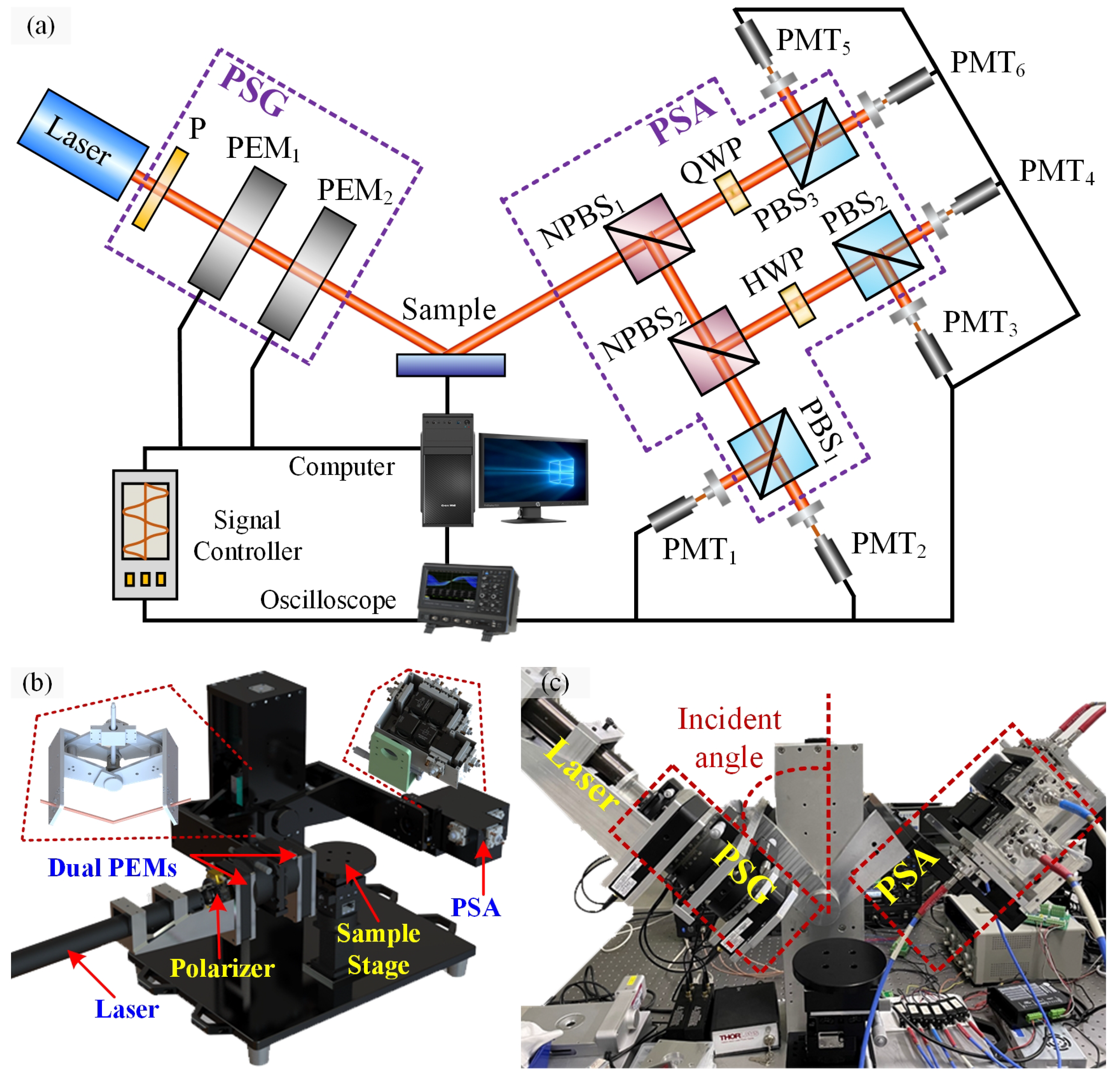
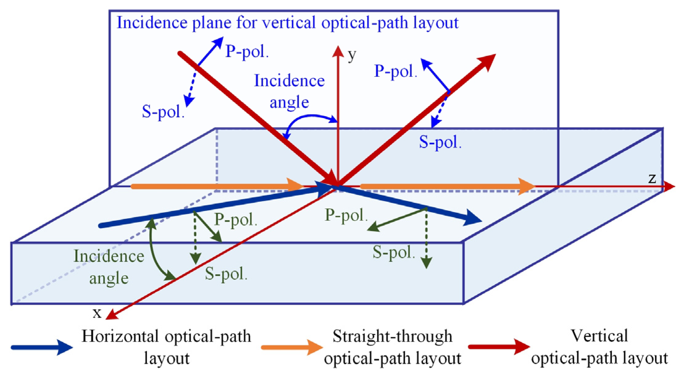
2. Instrument Prototype

Still following the traditional double-rotating compensator ellipsometer architecture [22], the vertical instrument uses a polarizer and two cascaded PEMs with different modulation frequencies as the PSG, and a six-channel Stokes polarimeter based on division-of-amplitude (DOA) as the PSA [27,28], which enables the avoidance of the mechanical rotation modulation of the compensator. The corresponding principle optical path is shown in Figure 1a. The whole-system settings of the instrument in order of light propagation are L-PSG-S-PSA-D, where L, S, and D stand for the laser source, the sample, and six photomultiplier tubes, respectively. By using a 5 mW He-Ne Laser (HNL050LB, Thorlabs, NJ, USA) with a central wavelength of 632.8 nm, a pre-polarized beam is projected into the PSG module, in which the fixed-azimuth linear polarizer (LPVIS100-MP2, Thorlabs, NJ, USA) and two PEMs (II/FS47 and II/FS50LR, Hinds, OR, USA) with phase modulation frequencies of 47.112 kHz and 50.006 kHz can jointly generate probe light with time-varying polarization. Using the period division method proposed by Zhang et al. [26], the probe light whose polarization state changes with time at a period of 11 µs can be generated by the PSG module, which is the key to realizing the high measurement time resolution. It should be noted that, with the longitudinal mode spacing of the He-Ne laser less than 435 MHz, the bandwidth of the probe beam is less than 0.0004 nm, which ensures the monochromaticity of the instrument’s measurement results.
Then, the PSA module collects the reflection or transmission light from the sample and splits it into three branches equally using two non-polarizing beam splitters (BS019 and BS013, Thorlabs, NJ, USA) with splitting ratios of 70:30 and 50:50, respectively. With three branches for polarization demodulation, the three Stokes parameters of the reflection or transmission light can be determined according to the DOA principle. Each polarization–demodulation branch consisted of a polarizing beam splitter (CCM1-PBS25-633/M, Thorlabs, NJ, USA) and two photomultiplier tubes (H10721 Series, Hamamatsu, Shizuoka Pref., Japan). Notably, a half-wave plate (WPMH05M-633, Thorlabs, NJ, USA) with a fast-axis azimuthal angle of −45°, and a quarter-wave plate (WPMQ05M-633, Thorlabs, NJ, USA) with a fast-axis azimuthal angle of 22.5° are used in the second and third polarization–demodulation branches, respectively. Since the photomultiplier tubes with a response time of 0.57 ns and two oscilloscopes (WaveSurfer-3000, Teledyne Lecroy, Chestnut Ridge, NY, USA) with bandwidth of 200 MHz are used as the signal detection module, it is possible to capture all the Stokes parameters of the reflection beam simultaneously in several nanoseconds. Thus, the Mueller matrix measurement with a period of 11 μs can be achieved. In order to ensure the synchronization of the signals collected by the six detection channels, a synchronous triggering and acquisition method based on the phase reference signal output by the PEM controller was utilized [26].
In the vertical optical path layout shown in Figure 1b, the ball screw assembly was used to alter the incident angle, which can realize an variable angle range of 45°~90° and an angular resolution of 0.1°. As shown in the left inset in Figure 1b, the slider driven by the motor makes a reciprocating linear motion on the guide rail, causing the rotation of the rotating arms via the four-bar linkage, which finally realizes the smooth adjustment of the incidence angle. Figure 1b shows the 3D structural model for the vertical high-speed MME, and the right inset presents the arrangement of the PSA module in detail. Correspondingly, Figure 1c exhibits the prototype of vertical high-speed MME.

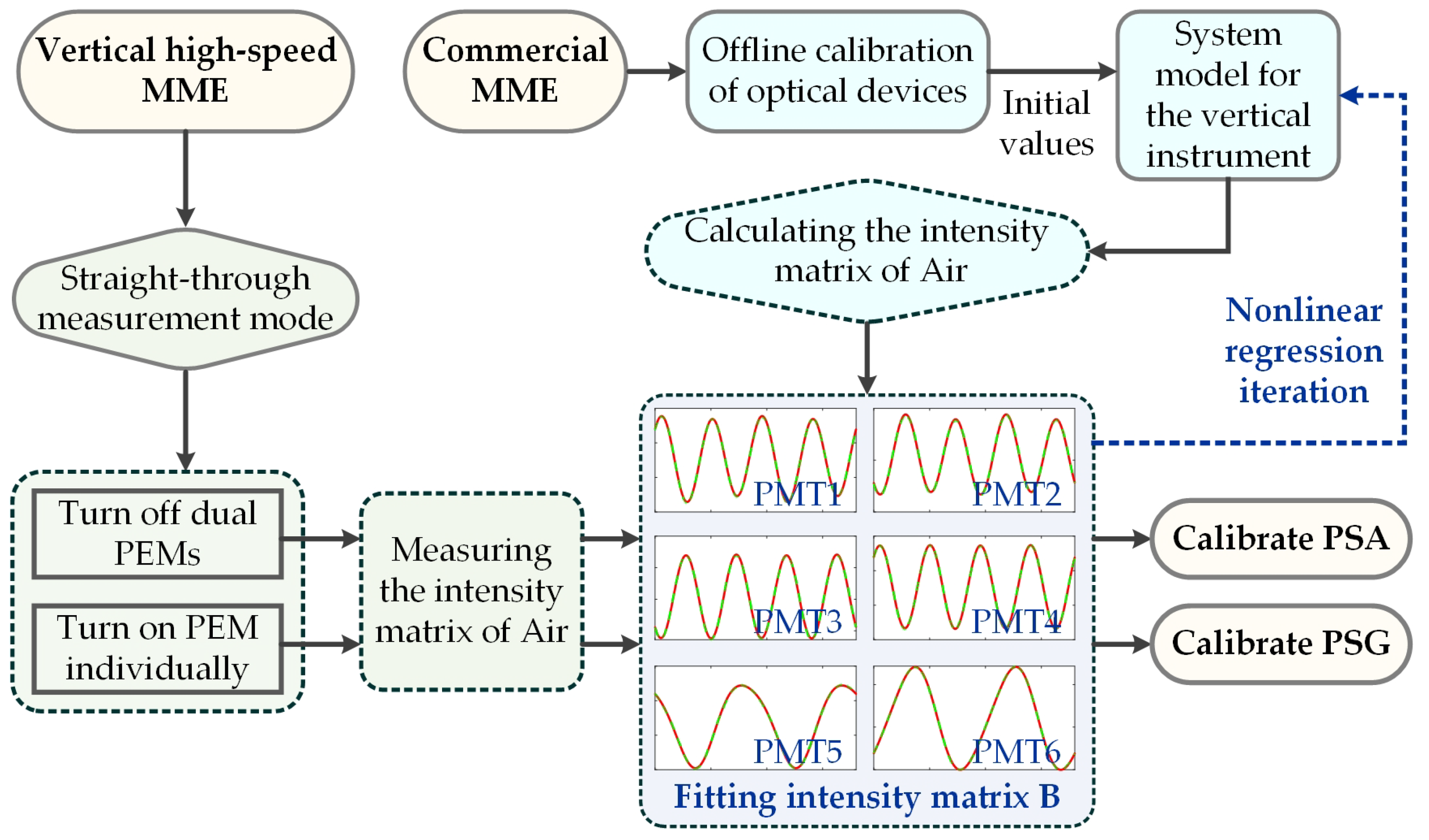
3. Calibration Method

Compared with the previous self-developed horizontal high-speed MME [26], the incidence plane of the vertical high-speed MME is in the vertical plane under the configuration of oblique incidence, which means that the reference plane for defining the polarization state has rotated 90°, as shown in Figure 2. Meanwhile, the incidence plane for the straight-through measurement mode of the vertical instrument has uncertainty and multi-solution, which is attributed to the parallel relationship between the probe light‘s wave vector and the normal vector of the sample surface in this measurement mode. That is why the systematic model of the horizontal instrument can be applied to the system calibration of the vertical instrument in the direct-through measurement mode rather than in the oblique measurement mode. Based on the above considerations, an updated systematic model was proposed, especially for the vertical instrument. Supposing the light source’s Stokes vector is Sin = [1, 1, 0, 0]T and the PEM can be considered as a retarder with time-varying retardance [29], the Stokes vector SPSG of the probe beam can be expressed as the following formula:
S PSG = R ( θ PEM 2 ) M RET ( δ PEM 2 ) R ( θ PEM 2 ) R ( θ PEM 1 ) M RET ( δ PEM 1 ) R ( θ PEM 1 ) R ( 90 ° ) R ( θ P ) M P R ( θ P ) S in ,
where MP and MRET are the Mueller matrices of the polarizer and the retarder, respectively. The detail expression of MP and MRET can be found in the literature [26,30]. R represents the rotation matrix. The angles θP, θPEM1, and θPEM2 are the azimuthal angles of the polarizer, and the first and second PEMs, respectively. The parameters δPEM1 and δPEM2 symbolize the time-varying phase retardance of the first and second PEMs, respectively, which can be expressed as the following formula:
δ i = δ p e a k ,   i sin ( 2 π f i t + φ i ) + δ s t a t i c ,   i i = P E M 1 ,   P E M 2 ,
where δpeak, i is the peak retardance of the ith PEM driven by a certain voltage. The parameter δstatic, i symbolizes the static retardance of the ith PEM, related to the birefringence properties of crystal in the PEM. The parameters fi and φi are the modulation frequency and the initial phase of the ith PEM, respectively, in which the nominal values of f1 and f2 are 42 kHz and 59 kHz, respectively. And t is the time variable.
In the six-channel PSA module, each detection channel can be represented by an ordered cascade of Mueller matrices for each optical element used in the channel. Since each channel only captures the light intensity, only the first row in the ordered cascade of Mueller matrices is required to represent polarization demodulation and sensing for each channel, as shown in the following formula:
a 1 = k 1 [ 1 0 0 0 ] [ R ( 90 ° ) M P B S R R ( 90 ° ) ] M N P B S 55 T M N P B S 73 R ,
a 2 = k 2 [ 1 0 0 0 ] [ R ( 90 ° ) M P B S T R ( 90 ° ) ] M N P B S 55 T M N P B S 73 R ,
a 3 = k 3 [ 1 0 0 0 ] [ R ( 90 ° ) M P B S R R ( 90 ° ) ] [ R ( θ H W P ) M H W P R ( θ H W P ) ] M N P B S 55 R M N P B S 73 R ,
a 4 = k 4 [ 1 0 0 0 ] [ R ( 90 ° ) M P B S T R ( 90 ° ) ] [ R ( θ H W P ) M H W P R ( θ H W P ) ] M N P B S 55 R M N P B S 73 R ,
a 5 = k 5 [ 1 0 0 0 ] [ R ( 90 ° ) M P B S R R ( 90 ° ) ] [ R ( θ Q W P ) M Q W P R ( θ Q W P ) ] M N P B S 73 T ,
a 6 = k 6 [ 1 0 0 0 ] [ R ( 90 ° ) M P B S T R ( 90 ° ) ] [ R ( θ Q W P ) M Q W P R ( θ Q W P ) ] M N P B S 73 T ,
where the coefficient ki with i = 1~6 represents the gain factor of each intensity detection channel in the PSA module. M P B S R and M P B S T are the Mueller matrices of the polarizing beam splitter in the reflection and transmission mode, respectively. M N P B S 55 R and M N P B S 55 T symbolize the Mueller matrices of the non-polarizing beam splitter, with a splitting ratio of 50:50 in the reflection and transmission mode, respectively. Similarly, M N P B S 73 R and M N P B S 73 T are the Mueller matrices of the non-polarizing beam splitter, with a splitting ratio of 70:30 in the reflection and transmission mode, respectively. MHWP and MQWP are the Mueller matrices of the half-wave plate and the quarter-wave plate, respectively. Parameters θHWP and θQWP are the azimuthal angles of the half-wave plate and the quarter-wave plate, respectively. The detailed expressions of these above Mueller matrices can be found in the literature [28,30,31]. Compared with the horizontal system reported in ref. [26], the essential difference is reflected in the spatial topological relationship between the reference plane for the amplitude division realized by the PSA module and the incidence plane of the measured sample. As for the horizontal optical-path layout design, the reference plane for the amplitude division is parallel with the incidence plane of the measured sample, while the orthogonal relationship between the two planes can be found in the current vertical optical-path layout design. Correspondingly, the reference planes for the polarization definition of the two optical-path layouts are completely different, so the measurement models of the two measurement systems are entirely different. That is to say, the Formulas (1) and (3)–(8) in the manuscript are different from Formulas (13) and (15) in ref. [26].
By combining these six vectors in order, an instrument matrix characterizing the PSA module can be generated, as shown in the following formula:
A = [ a 1 a 2 a 3 a 4 a 5 a 6 ] T ,
Then, the systematic model for the vertical high-speed MME can be established as the following formula:
B = A M S W = A M S [ S P S G ( t 1 ) S P S G ( t 2 ) S P S G ( t j ) S P S G ( t N ) ] ,
where SPSG(tj) is the Stokes vector of the probe beam generated by the PSG module at the moment tj. Ms represents the Mueller matrix of the sample to be tested. B = [I1, I2, ⋯, Ij, ⋯, IN] is the intensity matrix, in which Ij symbols the intensity vector consisted of six intensity values detected by the vertical high-speed MME at the moment tj.
The systematic model shown in Equation (10) can be used not only for calibrating the instrument’s system parameters, but also for extracting the samples’ measurands. By turning off the dual PEMs in the vertical high-speed MME under the straight-through measurement mode, the instrument matrix or the systematic parameters of the PSA module can be obtained by utilizing the air as the sample and fitting the light intensity matrix collected by the six detection channels. Then, with the first and second PEMs turning on, respectively, the systematic parameters of the two PEMs and the polarizer can be obtained by measuring the air again under the straight-through mode. The above calibration process will be shown as a flow chart in Figure 3. Correspondingly, a χ2 function was introduced to estimate the goodness-of-fit for the nonlinear least-squares regression analysis adopted in the calibration process.
χ 2 ( p ) = [ B m B c ( p , t ) ] T Σ B [ B m B c ( p , t ) ] ,
where p is the systematic parameter set of the PSG or PSA module. Bm and Bc are the measured and calculated intensity matrices, respectively, which have been normalized via the gain factors of the six detection channels. ΣB represents the Moore–Penrose inverse of the covariance matrix of the measured intensity matrix Bm. The initial values of parameter set p used for the regression iteration come from the offline calibration of corresponding optical devices using the commercial MME (RC2, J. A. Woollam Inc., Lincoln, NE, USA). It is worth emphasizing that the in situ calibration results of the PSA module will be displayed in terms of the instrument matrix rather than the system parameters of the optical components involved, while the in situ calibration results of the PSA module will be displayed in terms of the system parameter values of the PEMs. It should be noted that the in situ calibration of the PSA module means the determination of 31 systematic parameters via the regression analysis, which includes all elements of the 6 × 4 instrument matrix, the gain factors of the six detection channels, and the azimuth angle of the polarizer. Regression analysis to achieve this goal requires offline calibration of each component to provide fitting initial values of the instrument matrix. Regression analysis to achieve this goal requires the offline calibration of each component to provide iteration initial values of the instrument matrix in the fitting process.

4. Results and Discussion

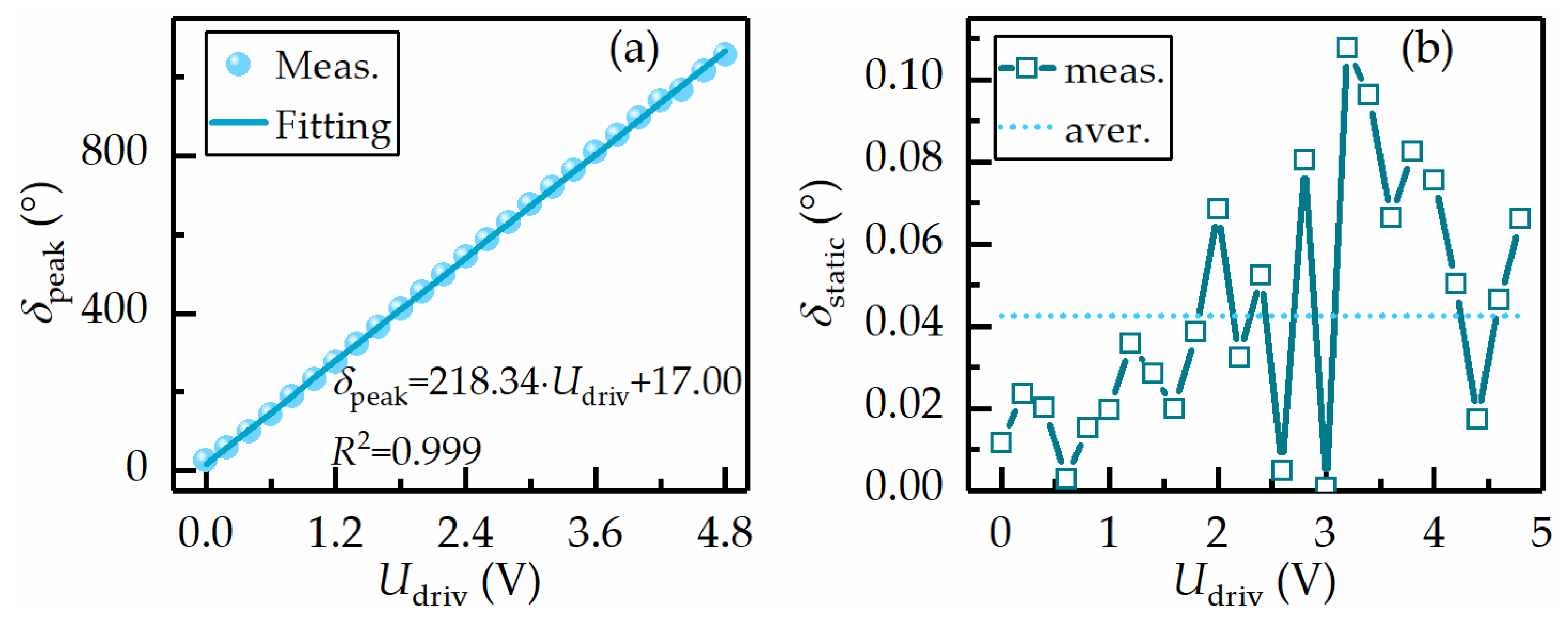
4.1. Calibration of PSA and PSG Module

Figure 4 shows the air’s Muller matrices, which are reported by the instrument without dual PEMs in the straight-through measurement mode, and reported by the theoretical calculation, respectively. According to the comparison results shown in Figure 4, it can be seen that the measured Mueller matrix generated by the calibration process of the PSA module is very close to the theoretical Mueller matrix of air, in which the absolute deviation of each element is about 0.005. Correspondingly, the instrument matrix characterizing the PSA module can be extracted from the calibration process, as shown in the following equation:
A = [ 0.287 0.320 0.284 0.233 0.276 0.264 0.268 0.294 0.120 0.096 0.119 0.104 0.035 0.040 0.087 0.074 0.148 0.147 0.006 0.006 0.225 0.184 0.179 0.179 ] ,
Subsequently, each PEM driven by different voltages was considered the sample to be tested, which was measured by the vertical instrument under the straight-through measurement mode. It is highly convenient for the in situ calibration of the PSG module by setting the azimuth angles of the polarizer, PEM1, and PEM2 to 45°, 0°, and 45°, respectively. Four systematic parameters can be determined from the calibration process, in which the analysis method has been previously reported [26]. Taking a PEM with a retardance modulation frequency of 42 kHz as an example, with the driving voltage changing from 0 V to 4.8 V, the PEM in the entire operating range can be in situ calibrated by repeating the above calibration process. Figure 5a,b shows the peak and static-phase retardance of the PEM under different driving voltages, respectively. Through performing linear fitting on the peak-phase retardance δpeak under different driving voltages Udriv, it can be found that the peak retardance δpeak had a strong linear dependence on the driving voltage, in which the linear factor and the truncation value were 218.34°/V and 17.00°, respectively. As the driving voltage gradually increased, the static phase retardance δstatic fluctuated around the average value of 0.043°, indicating no significant correlation between the two. Meanwhile, the static-phase retardance δstatic was close to 0, consistent with the PEM manufacturer’s setting.
The detailed parameters of dual PEMs used in the vertical high-speed MME, reported from the calibration process, are shown in Table 1. The retardance modulation frequencies of the two PEMs were very close to the nominal frequency, with both relative deviations less than 0.6%. The static retardance δstatic of the first and second PEMs were 0.041° and 0.036°, respectively, which are in accordance with the theoretical static retardance of 0°. The azimuthal angles of −0.34° and 44.82° for the PEMs are consistent with the pre-set values. The consistency observed above proves the accuracy and effectiveness of the constructed calibration method.

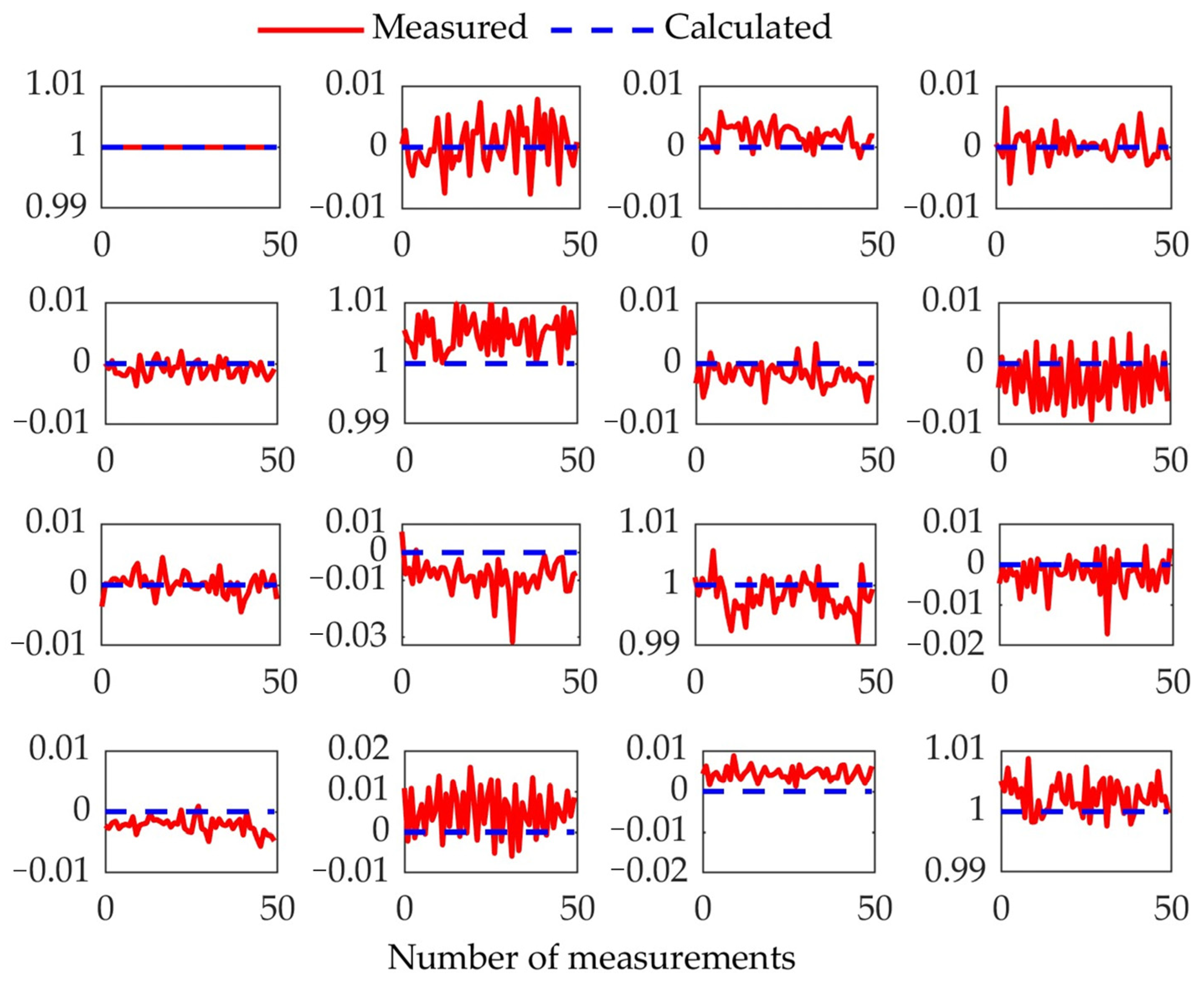
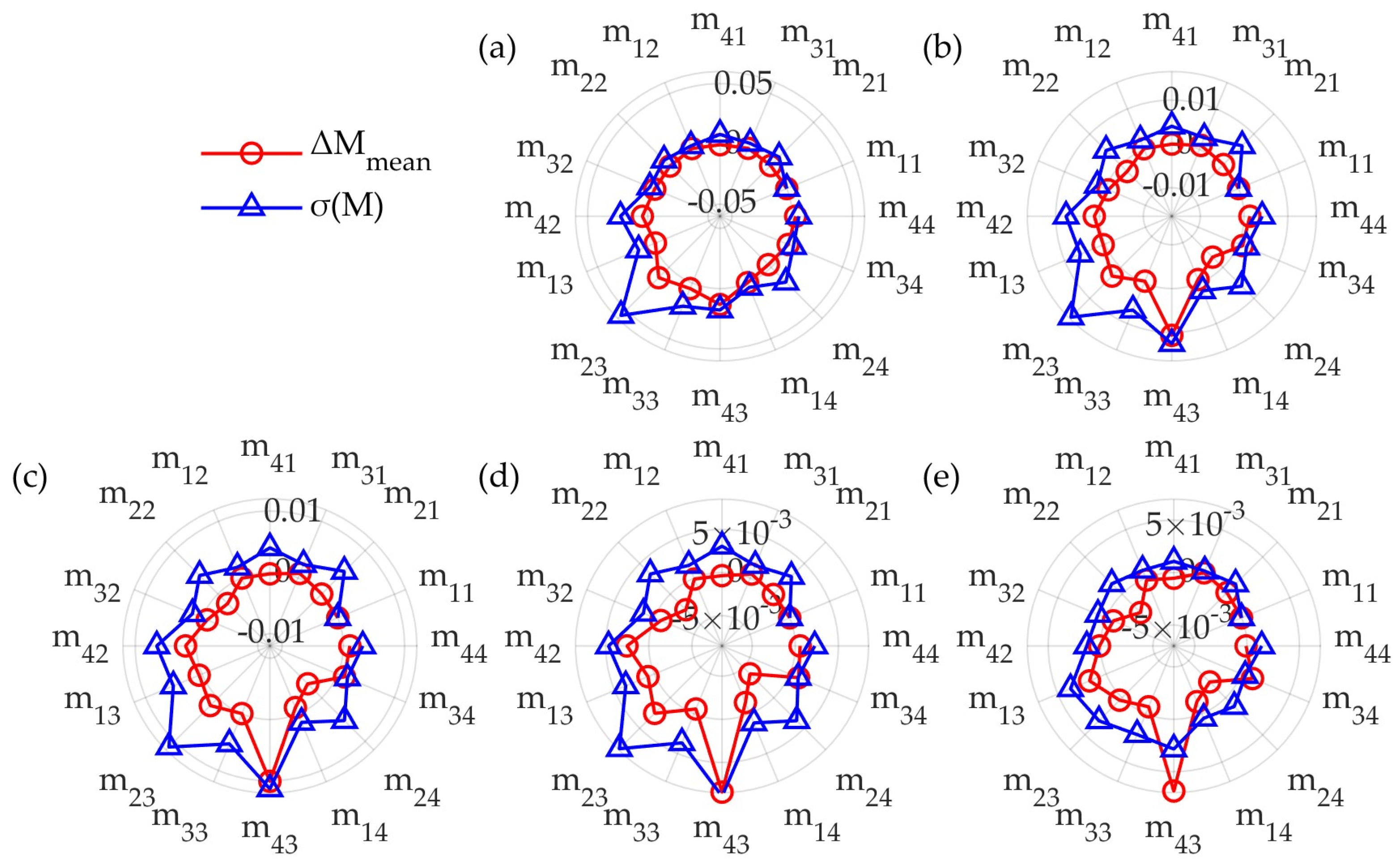
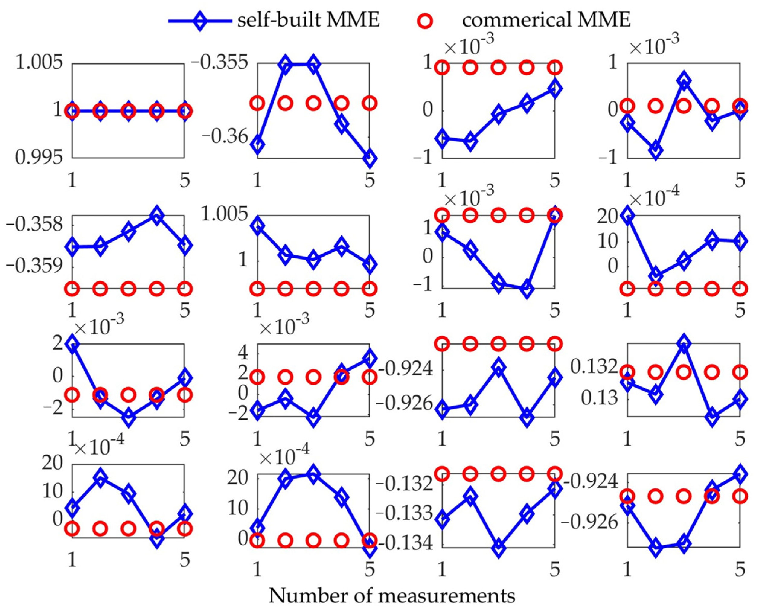
4.2. Measurement Performance of the Vertical Instrument

After implementing the above calibration process in the transmission mode, a standard SiO2 film with a nominal thickness of 20 nm was used as the sample under the incident angle of 45°, which allows for validating the above instrument matrix. The maximum deviation for all the elements in these two instrument matrices was less than 0.045, which indicates the high consistency between the results reported by the two calibration modes. Then, other standard SiO2 films with thicknesses of 1.7, 18, 25, and 31 nm were characterized by the vertical high-speed MME at the incident angle of 45°. The corresponding measured results were compared with those reported by the commercial MME to judge the measurement accuracy of the built instrument. In fact, the exceptionally high measurement accuracy of the RC2 Mueller matrix ellipsometer in the thickness measurement of standard SiO2 films has been widely demonstrated [32,33], which inspired us to use the results measured by the commercial ellipsometer as the reference values. Taking the 18nm thick SiO2 film as an example, the Mueller matrices reported by five repeated measurement experiments are shown in Figure 6, in which the results measured by a commercial ellipsometer are used as a reference to facilitate comparative analysis.
It can be easily noticed that the maximum deviation of most elements in the main diagonal block of the measured Mueller matrix from that reported by commercial MME was less than 0.004, and the maximum deviation of all elements in the off-diagonal block from that reported by commercial MME was less than 0.003. Only m22 and m33 in the main diagonal block of the measured Mueller matrix deviated from that reported by the commercial MME, with the deviations reaching 0.007 and 0.004, respectively, which might be attributed to the cumulative depolarization effect of each optical component in the instrument. Although there was a certain amount of deviation between individual elements and the reference value, the consistency of the above comparison results still fully illustrates the validity of the above calibration method and the measurement accuracy of the instrument. Correspondingly, the comparison between the thicknesses of the SiO2 films measured by the instrument and that reported by commercial MME is shown in Table 2. It should be noted that the measurement and reference values in Table 2 are the average thickness of five repeated film-thickness metrology experiments, while the standard deviation of the five thickness measurement results was used to evaluate the uncertainty of the measured thickness. As for the SiO2 films with thicknesses larger than 18.00nm, the measured thicknesses were very close to the reference values reported by the commercial MME, with relative deviations of less than 2.3%, which reflects the reliability and accuracy of measurement results. Although the relative thickness deviation for the 1.70 nm thick SiO2 film from the reference result is about 8.15%, their absolute deviation of less than 0.15nm still indicates the measurement accuracy.
Furthermore, the measurement temporal resolution of the instrument can be quantitatively evaluated by carrying out 50 repeated measurements of the air under the straight-through measurement mode in tandem with setting the sampling rate of the oscilloscope at 2 GHz. In each temporal-resolution test experiment, the instrument’s measurement configuration can be set as the optimal configuration under each corresponding measurement period, which can be obtained using an optimization algorithm satisfying specific constraints, such as the multi-objective genetic algorithm optimizing the Pareto optimal frontier [34]. The light-intensity signal sampling rate for each preset period is as optimal as possible. During the temporal-resolution test, the instrument performance was evaluated using each element’s average deviation and standard deviation for the 50 Mueller matrices of the air. The corresponding analysis results are shown in Figure 7. With a temporal resolution less than or equal to 5 µs, the average deviation for most Mueller matrix elements is on the order of 0.01, indicating that achieving the high temporal resolution in the measurement experiments often sacrifices the measurement precision. When the temporal resolution increased to 10 µs and above, the average deviation and standard deviation of each Mueller matrix element improved to less than 0.005, indicating that the instrument’s reliable temporal resolution in the measurement was about 10 μs.

5. Conclusions

In this work, we proposed a vertical high-speed MME that consists of a PSG based on the time-domain polarization modulation and a PSA based on division-of-amplitude polarization demodulation. The PSG was realized using a polarizer and two cascaded PEMs, while the PSA was realized using a six-channel Stokes polarimeter. On this basis, an in situ dual-step calibration method based on the correct definition of the polarization modulation and demodulation reference plane was proposed, enabling the precise calibration of the instrument by combining it with a time-domain light-intensity fitting algorithm. The measurement experiments of SiO2 films and an air medium prove the accuracy and feasibility of the proposed calibration method. After the precise calibration, the instrument can exhibit excellent measurement performance in the range of incident angles from 45° to 90°, in which the measurement time resolution is maintained at the order of 10 μs, the measurement accuracy of Mueller matrix elements is better than 0.007, and the measurement precision is better than 0.005. The above analysis fully demonstrates the potential application value of the proposed instrument.

Author Contributions

Conceptualization, J.L., S.Z., H.J. and S.L.; methodology, J.L., H.J. and S.Z.; software, J.L., S.Z., B.D., H.G. and J.Z.; validation, J.L., S.Z., H.J. and B.D.; formal analysis, H.G., J.Z., L.L. and S.L.; investigation, J.L., S.Z. and B.D.; resources, J.L., S.Z., B.D., H.G. and J.Z.; data curation, J.L. and B.D.; writing—original draft preparation, J.L., S.Z., H.J. and S.L.; writing—review and editing, J.L., S.Z., H.G., J.Z., H.J. and S.L.; visualization, J.L., S.Z. and L.L.; supervision, H.J. and S.L.; project administration, H.J. and S.L.; funding acquisition, H.J. and S.L. All authors have read and agreed to the published version of the manuscript.

Funding

This research was funded by National Natural Science Foundation of China (Grant Nos 52130504, 51975232, 52205592, 52305577), the Key Research and Development Plan of Hubei Province (Grant No. 2022BAA013), and the 2021 Postdoctoral Innovation Research Positions in Hubei Province (Grant No. 0106100226).

Institutional Review Board Statement

Not applicable.

Informed Consent Statement

No applicable.

Data Availability Statement

Data will be made available on request.

Acknowledgments

The authors would like to thank the technical support from the Experiment Center for Advanced Manufacturing and Technology in School of Mechanical Science & Engineering of HUST.

Conflicts of Interest

The authors declare no conflict of interest.

References

  1. Benjamin, I. Reaction dynamics at liquid interfaces. Annu. Rev. Phys. Chem. 2015, 66, 165–188. [Google Scholar] [CrossRef] [PubMed]
  2. Ferrera, M.; Magnozzi, M.; Bisio, F.; Canepa, M. Temperature-dependent permittivity of silver and implications for thermoplasmonics. Phys. Rev. Mater. 2019, 3, 105201. [Google Scholar] [CrossRef]
  3. Magnozzi, M.; Ferrera, M.; Mattera, L.; Canepa, M.; Bisio, F. Plasmonics of Au nanoparticles in a hot thermodynamic bath. Nanoscale 2019, 11, 1140–1146. [Google Scholar] [CrossRef] [PubMed]
  4. Xu, M.; Yang, J.; Zhang, S.; Liu, L. Role of electron-phonon coupling in finite-temperature dielectric functions of Au, Ag, Cu. Phys. Rev. B 2017, 96, 115154. [Google Scholar] [CrossRef]
  5. Manukyan, K.V.; Avetisyan, A.G.; Shuck, C.E.; Chatilyan, H.A.; Rouvimov, S.; Kharatyan, S.L.; Mukasyan, A.S. Nickel oxide reduction by hydrogen: Kinetics and structural transformations. J. Phys. Chem. C 2015, 119, 16131–16138. [Google Scholar] [CrossRef]
  6. Vendelbo, S.B.; Elkjær, C.F.; Falsig, H.; Puspitasari, I.; Dona, P.; Mele, L.; Morana, B.; Nelissen, B.J.; van Rijn, R.; Creemeer, J.F.; et al. Visualization of oscillatory behaviour of Pt nanoparticles catalysing CO oxidation. Nat. Mater. 2014, 13, 884–890. [Google Scholar] [CrossRef]
  7. Yu, J.; Yuan, W.; Yang, H.; Xu, Q.; Wang, Y.; Zhang, Z. Fast gas-solid reaction kinetics of nanoparticles unveiled by millisecond in situ electron diffraction at ambient pressure. Angew. Chem. Int. Ed. 2018, 57, 11344–11348. [Google Scholar] [CrossRef]
  8. Raeburn, J.; Cardoso, A.Z.; Adams, D. The importance of the self-assembly process to control mechanical properties of low molecular weight hydrogels. Chem. Soc. Rev. 2013, 42, 5143–5156. [Google Scholar] [CrossRef]
  9. Jiang, H.; Peng, H.; Chen, G.; Gu, H.; Chen, X.; Liao, Y.; Liu, S.; Xie, X. Nondestructive investigation on the nanocomposite ordering upon holography using Mueller matrix ellipsometry. Eur. Polym. J. 2019, 110, 123–129. [Google Scholar] [CrossRef]
  10. Gillmer, S.R.; Yu, X.; Wang, C.; Ellis, J.D. Robust high-dynamic-range optical roll sensing. Opt. Lett. 2015, 40, 2497–2500. [Google Scholar] [CrossRef]
  11. Saito, Y.; Arai, Y.; Gao, W. Detection of three-axis angles by an optical sensor. Sens. Actuator. A Phys. 2009, 150, 175–183. [Google Scholar] [CrossRef]
  12. Long, D.A.; Reschovsky, B.J.; LeBrun, T.W.; Gorman, J.J.; Hodges, J.T.; Plusquellic, D.F.; Stroud, J.R. High dynamic range electro-optic dual-comb interrogation of optomechanical sensors. Opt. Lett. 2022, 47, 4223–4326. [Google Scholar] [CrossRef] [PubMed]
  13. Bag, A.; Neugebauer, M.; Mick, U.; Christiansen, S.; Schulz, S.A.; Banzer, P. Towards fully integrated photonic displacement sensors. Nat. Commun. 2020, 11, 2915. [Google Scholar] [CrossRef]
  14. Petkovšek, R.; Petelin, J.; Možina, J.; Bammer, F. Fast ellipsometric measurements based on a single crystal photoelastic modulator. Opt. Express 2010, 18, 21410–21418. [Google Scholar] [CrossRef] [PubMed]
  15. Zhang, S.; Wang, L.; Yi, A.; Gu, H.; Chen, X.; Jiang, H.; Liu, S. Dynamic modulation performance of ferroelectric liquid crystal polarization rotators and Mueller matrix polarimeter optimization. Front. Mech. Eng. 2020, 15, 256–264. [Google Scholar] [CrossRef]
  16. Zhang, L.; Liu, J.; Zhu, J.; Jiang, H.; Liu, S. Femtosecond laser induced damaging inside fused silica observed by a single-pulse ultrafast measurement system. Opt. Express 2022, 30, 26111–26119. [Google Scholar] [CrossRef]
  17. Barroo, C.; Wang, Z.; Schlögl, R.; Willinger, M. Imaging the dynamics of catalysed surface reactions by in situ scanning electron microscopy. Nat. Catal. 2020, 3, 30–39. [Google Scholar] [CrossRef]
  18. Zhou, L.; Jiang, C.; Lin, Q. Entropy analysis and grey cluster analysis of multiple indexes of 5 kinds of genuine medicinal materials. Sci. Rep. 2022, 12, 6618. [Google Scholar] [CrossRef]
  19. Wehrenberg, C.E.; McGonegle, D.; Bolme, C.; Higginbotham, A.; Lazicki, A.; Lee, H.J.; Nagler, B.; Park, H.-S.; Remington, B.A.; Rudd, R.E.; et al. In situ X-ray diffraction measurement of shock-wave-driven twinning and lattice dynamics. Nature 2017, 550, 496–499. [Google Scholar] [CrossRef]
  20. Chen, X.; Gu, H.; Liu, J.; Chen, C.; Liu, S. Advanced Mueller matrix ellipsometry: Instrumentation and emerging applications. Sci. China Technol. Sc. 2022, 65, 2007–2030. [Google Scholar] [CrossRef]
  21. Bian, S.; Cui, C.; Arteaga, O. Mueller matrix ellipsometer based on discrete-angle rotating Fresnel rhomb compensators. Appl. Opt. 2021, 60, 4964–4971. [Google Scholar] [CrossRef] [PubMed]
  22. Liu, S.; Chen, X.; Zhang, C. Development of a broadband Mueller matrix ellipsometer as a powerful tool for nanostructure metrology. Thin Solid Films 2015, 584, 176–185. [Google Scholar] [CrossRef]
  23. Atalar, O.; Van Laer, R.; Safavi-Naeini, A.H.; Arbabian, A. Longitudinal piezoelectric resonant photoelastic modulator for efficient intensity modulation at megahertz frequencies. Nat. Commun. 2022, 13, 1526. [Google Scholar] [CrossRef] [PubMed]
  24. López-Téllez, J.M.; Bruce, N.C. Mueller-matrix polarimeter using analysis of the nonlinear voltage–retardance relationship for liquid-crystal variable retarders. Appl. Opt. 2014, 53, 5359–5366. [Google Scholar] [CrossRef] [PubMed]
  25. Marco, D.; López-Morales, G.; Sanchez-López, M.M.; Lizana, Á.; Moreno, I.; Campos, J. Customized depolarization spatial patterns with dynamic retardance functions. Sci. Rep. 2021, 11, 9415. [Google Scholar] [CrossRef] [PubMed]
  26. Zhang, S.; Jiang, H.; Gu, H.; Chen, X.; Liu, S. High-speed Mueller matrix ellipsometer with microsecond temporal resolution. Opt. Express 2020, 28, 10873–10887. [Google Scholar] [CrossRef]
  27. Zhang, S.; Jiang, H.; Gu, H.; Chen, X.; Liu, S. Attitude metrology based on the field-of-view effect of birefringence using high-speed polarimetry. Opt. Lett. 2020, 45, 2074–2077. [Google Scholar] [CrossRef]
  28. Liu, J.; Zhang, C.; Zhong, Z.; Gu, H.; Chen, X.; Jiang, H.; Liu, S. Measurement configuration optimization for dynamic metrology using Stokes polarimetry. Meas. Sci. Technol. 2018, 29, 054010. [Google Scholar] [CrossRef]
  29. Arteaga, O.; Freudenthal, J.; Wang, B.; Kahr, B. Mueller matrix polarimetry with four photoelastic modulators: Theory and calibration. Appl. Opt. 2012, 51, 6805–6817. [Google Scholar] [CrossRef]
  30. Fujiwara, H. Spectroscopic Ellipsometry Principles and Applications; John Wiley & Sons, Ltd.: Chichester, UK, 2007; pp. 52–79. [Google Scholar]
  31. Zhang, S.; Gu, H.; Liu, J.; Jiang, H.; Chen, X.; Zhang, C.; Liu, S. Characterization of beam splitters in the calibration of a six-channel Stokes polarimeter. J. Opt. 2018, 20, 125606. [Google Scholar] [CrossRef]
  32. Ehrstein, J.; Richter, C.; Chandler-Horowitz, D.; Vogel, E.; Young, C.; Shah, S.; Maher, D.; Foran, B.; Hung, P.Y.; Diebold, A. A comparison of thickness values for very thin SiO2 films by using ellipsometric, capacitance-voltage, and HRTEM measurements. J. Electrochem. Soc. 2006, 153, F12–F19. [Google Scholar] [CrossRef]
  33. Herzinger, C.M.; Johs, B.; McGahan, W.A.; Woollam, J.A. Ellipsometric determination of optical constants for silicon and thermally grown silicon dioxide via a multi-sample, multi-wavelength, multi-angle investigation. J. Appl. Phys. 1998, 83, 3323–3336. [Google Scholar] [CrossRef]
  34. Ramirez-Atencia, C.; Bello-Orgaz, G.; R-Moreno, M.D.; Camacho, D. Solving complex multi-UAV mission planning problems using multi-objective genetic algorithms. Soft Comput. 2017, 21, 4883–4900. [Google Scholar] [CrossRef]
Figure 1. Vertical high-speed Mueller matrix ellipsometer. (a) Principle-optical-path schematic diagram; (b) 3D-modeling schematic diagram; and (c) self-developed MME prototype. P, polarizer; PEM1 and PEM2, photoelastic modulators; NPBS1 and NPBS2, non-polarization beam splitters with splitting ratios of 70:30 and 50:50, respectively; PBS1, PBS2, and PBS3, polarization beam splitters with the same specifications; QWP, quart-wave plate; HWP, half-wave plate; PMT1, PMT2, PMT3, PMT4, PMT5, and PMT6, photomultiplier tubes with the same specifications; PSG, polarization state generator; PSA: polarization state analyzer. The left inset in (b) shows the varying angle mechanism based on the ball screw assembly, while the right inset in (b) exhibits the actual PSA module.
Photonics 10 01064 g001
Figure 2. Reference planes for defining the polarization state basis vectors in the vertical and horizontal instrument.
Photonics 10 01064 g002
Figure 3. Flow chart of the calibration process for the vertical instrument.
Photonics 10 01064 g003
Figure 4. Mueller matrices of the air reported by the vertical instrument without the PEMs working under the straight-through mode. The results were obtained from 50 repeated-measurement experiments.
Photonics 10 01064 g004
Figure 5. Peak- (a) and static (b)-phase retardance of the PEM with retardance modulation frequency of 42 kHz under different driving voltages.
Photonics 10 01064 g005
Figure 6. Mueller matrices of 18 nm thick SiO2 film reported by the self-built MME and the commercial MME.
Photonics 10 01064 g006
Figure 7. Mueller matrix elements’ average deviation and standard deviation generated by 50 repeated measurements of the air under different temporal resolutions. From (a) to (e), the results correspond to the preset temporal resolutions of 2 μs, 4 μs, 5 μs, 10 μs, and 50 μs, respectively.
Photonics 10 01064 g007
Table 1. Systematic parameters of the dual PEMs obtained from the in situ calibration process.
Specificationδpeak (°)f (kHz)φ (°)δstatic (°)θPEM (°)
II/FS42LR1056.742.05260.90.043−0.34
II/FS60LR1078.859.64129.90.03644.82
Table 2. Comparison between the SiO2 films’ thicknesses determined by the two instruments.
Nominal Value
(nm)
Measured Value
(nm)
Reference Value
(nm)
Deviation
(nm)
Relative
Deviation
1.701.84 ± 0.621.69 ± 0.010.158.15%
18.0017.86 ± 0.2318.10 ± 0.02−0.241.34%
25.0025.13 ± 0.1325.31 ± 0.02−0.180.72%
31.0031.42 ± 0.3230.72 ± 0.040.722.29%
Disclaimer/Publisher’s Note: The statements, opinions and data contained in all publications are solely those of the individual author(s) and contributor(s) and not of MDPI and/or the editor(s). MDPI and/or the editor(s) disclaim responsibility for any injury to people or property resulting from any ideas, methods, instructions or products referred to in the content.

