Article

Piston Detection of Optical Sparse Aperture Systems Based on an Improved Phase Diversity Method

1
Changchun Institute of Optics, Fine Mechanics and Physics, Chinese Academy of Sciences, Changchun 130033, China
2
University of Chinese Academy of Sciences, Beijing 100049, China
3
Key Laboratory of On-Orbit Manufacturing and Integration for Space Optics System, Chinese Academy of Sciences, Changchun 130033, China
*
Authors to whom correspondence should be addressed.
Photonics 2023, 10(9), 1039; https://doi.org/10.3390/photonics10091039
Submission received: 19 August 2023 / Revised: 1 September 2023 / Accepted: 5 September 2023 / Published: 12 September 2023
(This article belongs to the Special Issue Optical Precision Manufacturing and Processing)

Abstract

:
The piston error has a significant effect on the imaging resolution of the optical sparse aperture system. In this paper, an improved phase diversity method based on particle swarm optimization and the sequential quadratic programming algorithm is proposed, which can overcome the drawbacks of the traditional phase diversity method and particle swarm optimization, such as the instability that results from polychromatic light conditions and premature convergence. The method introduces factor β in the stage of calculating the objective function, and combines the advantages of a heuristic algorithm and a nonlinear programming algorithm in the optimization stage, thus enhancing the accuracy and stability of piston detection. Simulations based on a dual-aperture optical sparse aperture system verified that the root mean square error obtained by the method can be guaranteed to be within 0.001λ (wavelength), which satisfies the requirement of practical imaging. An experimental test was also conducted to demonstrate the performance of the method, and the test results showed that the quality of the image after piston detection and correction improved significantly compared to images with the co-phase error.

1. Introduction

The detection accuracy requirements of optical telescopes are constantly increasing. The angular resolution and light gathering ability of telescopes are directly related to the aperture. The larger the aperture of a telescope, the higher the angular resolution and the better the imaging effect [1]. However, large aperture telescopes present difficulties in transportation and installation. The increase in the aperture of the primary mirror makes the cost and manufacturing difficulty also increase dramatically. Therefore, the optical sparse aperture system (OSAS) was proposed [2]. The OSAS uses multiple separated mirrors and can achieve high-resolution imaging performance [3]. Multiple sub-aperture telescopes are easier to implement for fabrication and transportation than conventional large-aperture telescopes. Two implementations of OSAS are segmented telescopes, such as the James Webb Space Telescope [4] and the Extremely Large Telescope [5], and telescope arrays, such as the Large Binocular Telescope [6].
To obtain sufficient resolution, the co-phase error between sub-apertures should be controlled within 0.1λ [7]. The co-phase error is divided into the piston error and tip/tilt error. For tip/tilt error correction, conventional wavefront detectors can be used. Therefore, in this paper, a study is conducted on the piston error.
The correction of the piston error can usually be divided into two types: intensity techniques, in which measurements are made directly from intensity distributions or streaks, such as modified Shack–Hartmann sensing [8,9], dispersed fringes sensors [10], pyramidal sensors [11], and interferometry with masks and diffracting components [12,13]; and modulation transfer function (MTF) techniques, which can extract the peak around the MTF from piston errors, such as chromatic phase diversity (PD) [14,15], inter-segment piston sensors [16], and calibration-retrieve sensing [17,18]. When these methods are used for piston correction, complex optics need to be introduced into the optical path. Additionally, despite their wide capture ranges and high accuracies, these methods are constrained by the object’s size. Before an extended object is observed, first, optical sparse aperture systems can be phased with a point source. It would be difficult to correct the systems using the methods mentioned above when pistons will again inevitably appear because of turbulence during the observation of the extended object [19]. The PD method, which is typically based on focused and slightly defocused images, removes all ambiguities and allows piston reconstruction regardless of the size of the object observed [20,21]. Compared with other methods, the PD method has the advantages of a simple optical system structure and high spatial resolution [22,23].
The defocus amount is known and a focal image is required in the traditional PD method when it is solved for monochromatic light and polychromatic light. However, the absolutely accurate focus position of the optical system is often difficult to locate. In this paper, PD is adaptively changed to use two defocused images. Additionally, when PD is used for polychromatic light cases, the numerical value of the objective function is too large in the solving process, which often leads to the loss of the optimal solution of various optimization algorithms. In this paper, factor β is introduced when the point spread function (PSF) is calculated to solve this problem.
However, when PD calculations are performed, the solution based only on the heuristic algorithm is unstable and the true value may not be found. To address this drawback, in this paper, a hybrid optimization algorithm that consists of particle swarm optimization (PSO) and sequential quadratic programming (SQP) is proposed. PSO has the advantages of fast convergence, few parameters, and adequate information exchange in high-dimensional nonlinear optimization problems [24]. Compared with other nonlinear programming algorithms, such as the gradient descent method and Newton’s method, SQP has a faster convergence speed and higher solution accuracy [25]. The combination of the two algorithms ensures the accuracy of the solution.
The simulation results showed that the proposed hybrid optimization algorithm converged quickly, and the results of multiple iterations showed that the algorithm was stable. Simulation examples also verified the effectiveness of the improved PD method proposed in this paper. Additionally, the monochromatic light experimental test was performed and the test results matched the simulation results.
The remainder of this paper is structured as follows: In Section 2, the principle of the PD method for the OSAS is reviewed. In this section, the theories of PSO and SQP are also introduced. Then, in Section 3, the drawbacks of PD, PSO, and SQP are illustrated. Additionally, the PD method is improved to increase the sensing accuracy of the piston error and the hybrid optimization algorithm PSO-SQP is proposed, which is stable and efficient. Furthermore, numerical simulations of piston detection for a dual-aperture OSAS under monochromatic and polychromatic illumination were performed to verify the effectiveness of the algorithm improvements and are discussed in Section 4. Subsequently, in Section 5, an experimental test for the piston detection and correction of a dual-aperture OSAS was performed, which further demonstrated the stability and effectiveness of the improved PD method based on the PSO-SQP algorithm. Then, in Section 6, discussions on the proposed method were conducted from aspects of the simulation and the experiment. Finally, in Section 7, the conclusions of this study are summarized.

2. Theory

2.1. PD Method Theory

The PD method is an image-based co-phase error detection technique. Figure 1 shows the optical path of the PD method used in OSAS. When incident light is quasi-monochromatic incoherent light, and the optical imaging system is assumed to be a linear space invariant system, the intensity distribution of the noiseless image plane can be modeled as
d k x , y = o x , y p s f k x , y   ,
where dk denotes the image received by the kth optical channel, o denotes the ideal target, psfk denotes the PSF of the kth optical channel, * denotes two-dimensional convolution, and (x,y) denotes the coordinate vector on the image plane. PSF can be obtained using the following formula:
p s f k ( x , y ) = F P ( ε , η ) e x p ( i φ k ( ε , η ) ) 2   ,
where F denotes the Fourier transform, (ε,ŋ) denotes the coordinate vector of the aperture plane, P denotes the aperture function, and φk denotes the wavefront phase of the kth channel, which can be expressed as follows:
φ k ε , η = ϕ n ε , η + k ε , η   ,
where Δk denotes the aberration of the kth channel and ϕn denotes the co-phase error of the nth submirror, which can be expressed as follows:
ϕ n ε , η = i = 1 3 a n i Z i   ,
where Zi denotes the ith Zernike polynomial and ani denotes the ith coefficient of the Zernike polynomial of the nth submirror.
Furthermore, the objective function is constructed using the least square method. According to Parseval’s theorem and the convolution theorem, the objective function can be obtained in the frequency domain:
E = k = 1 K D k ( u , v ) O ( u , v ) × O T F k ( u , v ) 2   ,
where Dk(u,v), O(u,v), and OTFk(u,v) are the Fourier transforms of dk(x,y), o(x,y), and psfk(x,y), respectively. The simplified form of the objective function can be obtained using the partial differential method:
E = u , v k = 1 K D k ( u , v ) 2 u , v k = 1 K D k ( u , v ) O T F k * ( u , v ) 2 k = 1 K O T F k ( u , v ) 2   .
According to Equation (6), the objective function is only related to the optical transfer function (OTF) of the system and the images received by the camera. Therefore, the objective function obtained by the PD method is eventually transformed into a large-scale nonlinear optimization problem.
However, because the denominator of the objective function may be zero, the minimization calculation of the objective function becomes unstable or fails during optimization. According to the Tikhonov regularization principle, the objective function can be rewritten as
E = u , v k = 1 K D k ( u , v ) 2 u , v k = 1 K D k ( u , v ) O T F k * ( u , v ) 2 γ + k = 1 K O T F k ( u , v ) 2   ,
where γ is the regularization coefficient and an extremely small positive number.
For wide-spectrum imaging, Equations (1)–(7) are still satisfied, where the PSF corresponds to the psfbroad of all wavelengths in the entire spectral region. According to the intensity superposition principle, the psfbroad of a wide spectrum is the weighted sum of the PSFs of all wavelengths:
p s f b r o a d = α λ p s f λ d λ   .
Equation (8) also can be written as
p s f b r o a d = α λ p s f λ λ   ,
where α is the weighting factor of λ, Δλ is the sampling interval of the calculated wavelength, and psfλ is the PSF when a single wavelength beam with λ is imaged in the current optical system. The relationship between the image’s frequency spectrum and the ideal target’s frequency spectrum is as follows:
D b r o a d u , v = O b r o a d u , v × O T F b r o a d u , v   ,
where OTFbroad denotes the OTF of all wavelengths in the entire spectral region.

2.2. PSO Theory

PSO is a global heuristic optimization algorithm that was proposed by American scholars Kennedy and Eberhart in 1995 [26]. The algorithm relies on group optimization, which refers to the update history of individuals and the group used to guide the optimization search process. The algorithm has few parameters and a simple operation, and can use the optimal information of individual evolution and the optimal information of population evolution to guide the iterative search of particles. At the beginning of the algorithm, PSO is initialized with a swarm of random particles, and then the optimal solution is determined through iteration. In each iteration, the particle updates itself by tracking two extreme values. The first extreme value is the optimal solution determined by the particle itself, which is called the individual extremum. The other extreme value is the optimal solution currently determined by the entire population, which is called the global extremum.
Suppose that in the D-dimensional target search space, N particles form a community, where the ith particle is represented as a D-dimensional vector:
X i = x i 1 , x i 2 , x i 3 , , x i D , i = 1 , 2 , 3 , , N   .
The flight speed of the ith particle is also a D-dimensional vector, denoted by
V i = v i 1 , v i 2 , v i 3 , , v i D   .
The optimal position searched thus far by the ith particle is called the individual extremum, denoted by
p b e s t = p i 1 , p i 2 , p i 3 , , p i D   .
The optimal position searched thus far by the entire PSO is called the global extremum, denoted by
g b e s t = ( p g 1 , p g 2 , p g 3 , , p g D )   .
When these two optimal values are determined, the particle updates its velocity and position according to the following formula:
v i d = ω × v i d + c 1 r 1 ( p i d x i d ) + c 2 r 2 ( p g d x i d ) , d = 1 , 2 , 3 , , D   .
x i d = x i d + v i d   ,
where ω is the inertia weight coefficient, c1 and c2 are the learning factors, and r1 and r2 are 0–1 uniform random numbers.

2.3. SQP Theory

SQP is widely used to solve practical optimization problems. It outperforms all other nonlinear programming methods in terms of efficiency, accuracy, and percentage of successful solutions. When SQP is used to compute the constrained optimization problem, a quadratic programming (QP) subproblem is first constructed at each iteration point, and then the solution of the subproblem is used as the iterative search direction. Finally, the search direction is searched in one dimension until the solution of the constrained optimization problem is approximated.
The main idea of SQP is to obtain the search direction of the design variable and the Lagrange multiplier variable by solving the QP subproblem successively, and then obtain the optimal solution by iteration.
For a nonlinear programming problem with constraints, the optimization formulation can be expressed as
M i n f ( x ) s . t   g i ( x ) = 0         i = 1 , 2 , 3 , , m e               g i ( x ) 0         i = m e + 1 , m e + 2 , , m   ,
where x is the design variable, f(x) is the objective function, gi(x) is the constraint condition, me is the number of equal constraints, and m is the total number of constraints.
The QP subproblem can be expressed as follows:
M i n   1 2 d k T H k d k + ( f ( x k ) ) T d k s . t   ( g i ( x ) ) T d k + g i ( x ) = 0         i = 1 , 2 , 3 , , m e               ( g i ( x ) ) T d k + g i ( x ) 0         i = m e + 1 , m e + 2 , , m   ,
where Hk is the Lagrange Hessian matrix at the kth iteration, dk is the search direction, and ▽ is the gradient.
The QP subproblem needs to be solved using the quadratic approximation function of the Lagrange function:
L x , ρ = f x + i = 1 m ρ i g i x   ,
where L is the Lagrange function and ρ is the Lagrange multiplier. The kth iteration produces the next iteration:
x k + 1 = x k + α k d k   ,
where α is the step size.
Because the objective function is non-convex, SQP requires a local minimum as the initial value of the iteration. In this paper, as a local optimizer, SQP determines the second accurate solution in the optimal region explored by PSO.

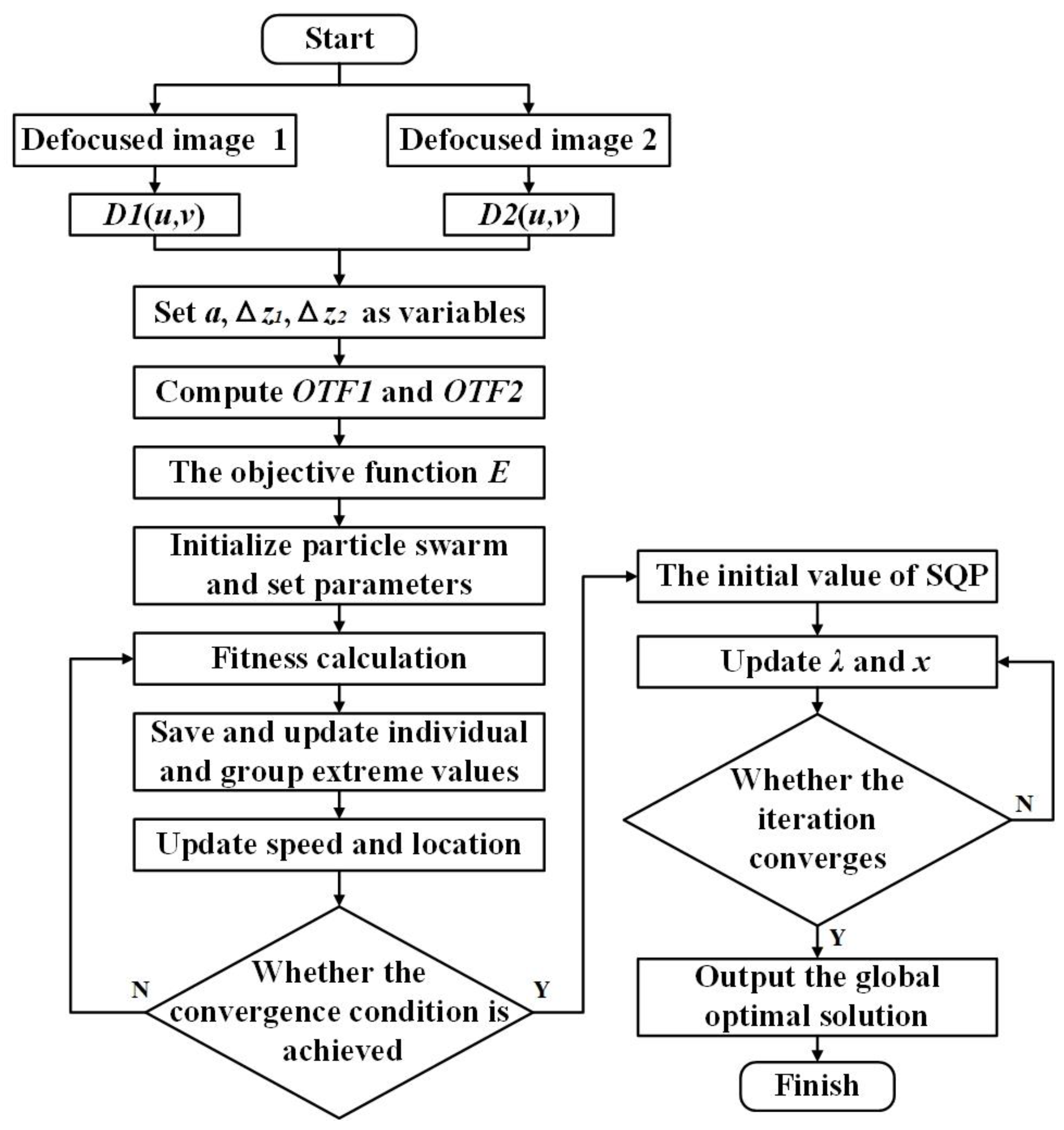
3. Improvements of PD and the Optimization Algorithms

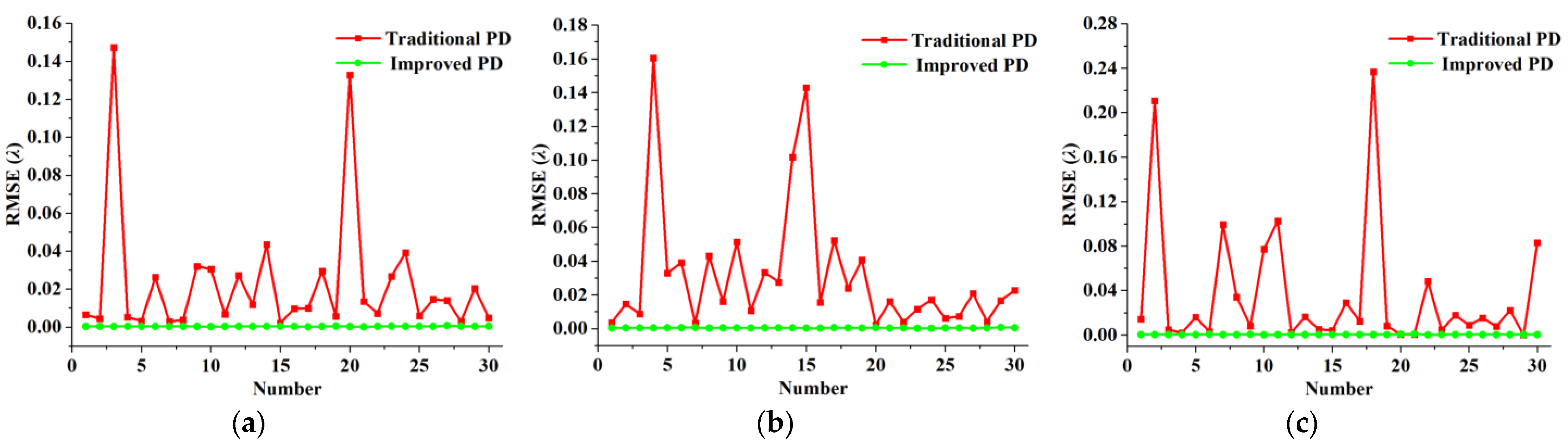
3.1. Improvement of PD

The PD method requires two images, one in focus and another with a known defocus amount as the calculation input. However, in a practical application, the accurate focus position and defocus amount of the optical system are often difficult to provide. When the PD method is applied to the co-phase error detection of OSAS, because OSAS has high requirements for the co-phase accuracy, the insufficiently accurate input of the PD method easily reduces the sensing accuracy of the co-phase error. As shown in Figure 1, in this paper, the PD method is adaptively changed to use the images at two defocus positions as the solution input. In the optimization process, the two defocus quantities and the piston error are calculated together as design variables to improve the sensing accuracy of the co-phase error.
Additionally, when PD is used for polychromatic light cases, the numerical value of the objective function is too large in the solving process, which often leads to various optimization algorithms failing to converge. In this paper, factor β is introduced when the PSF is calculated to solve this problem:
β = 1 ( p s f i d e a l ) m a x   ,
where (psfideal)max is the maximum value of the ideal PSF. Then, the frequency spectrum of the image received by the kth optical channel and the OTF of the kth optical channel can be expressed as
d k β x , y = β d k x , y D k β u , v = F ( d k β ( x , y ) )   , p s f k β x , y = β p s f k x , y O T F k β u , v = F ( p s f k β ( x , y ) )   .
According to Equation (7), the final objective function can be expressed as
E β = u , v k = 1 K D k β ( u , v ) 2 u , v k = 1 K D k β ( u , v ) O T F k β * ( u , v ) 2 γ + k = 1 K O T F k β ( u , v ) 2   .

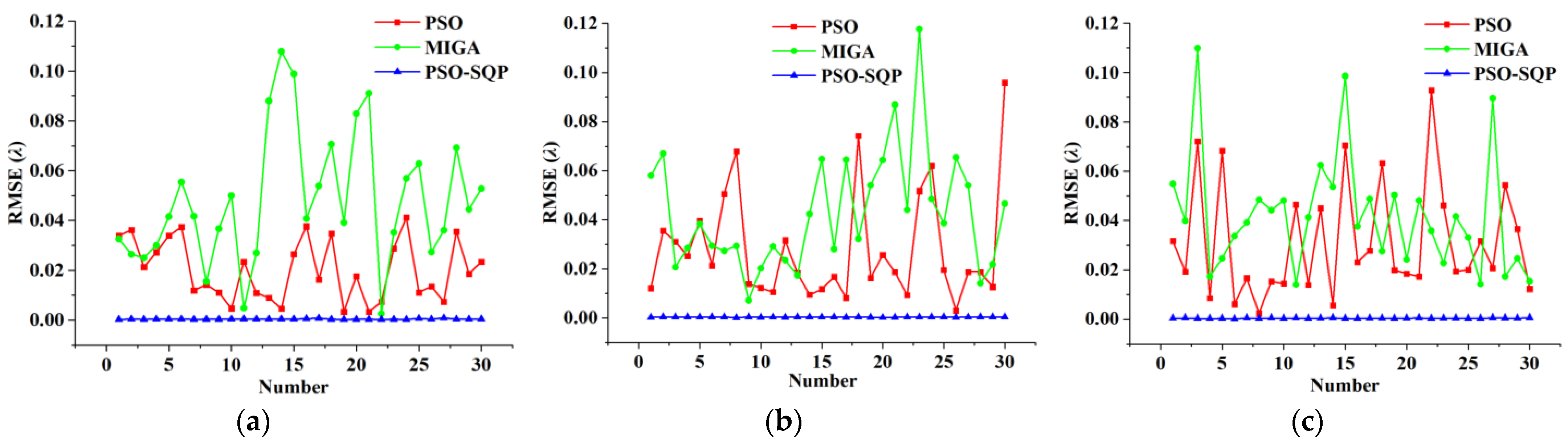
3.2. Improvement of the Optimization Algorithms

Although PSO has the advantages of a high information utilization rate, fast convergence speed, and simple operation, the information interaction between particles means that particles that are not in the current optimal position quickly converge to the global optimal position. If the flight speed is not limited, there is a high probability that the global optimal solution will be missed in the iteration process. The flight speed of particles directly affects the global convergence performance of the algorithm. Therefore, without effective control of the speed of the algorithm, defects can occur, such as slow convergence speed and premature optimization results in the post-optimization period.
Similarly, SQP also has inherent shortcomings. The selection of the initial value has a great influence on the calculation efficiency and accuracy of SQP; hence, a reasonable initial value is required to use this method. However, because of the lack of data support, it is usually difficult to provide a reasonable initial value at the beginning of the optimization calculation.
The combination of PSO and SQP is proposed in this paper to create the new hybrid optimization algorithm PSO-SQP. It mainly uses the global optimization ability of PSO and the accurate solution and fast convergence ability of SQP to avoid their shortcomings and complement their advantages. As shown in Figure 2, PSO is first used for iterative calculation and a global approximate optimal solution is obtained. After the specified PSO termination standard is reached, SQP is applied, the PSO solution is considered as the initial value, and the gradient method is used to search for the final global optimal solution. Thus, the PSO-SQP algorithm not only has strong development and exploration ability but can also determine the global optimal solution quickly and accurately.

4. Simulation

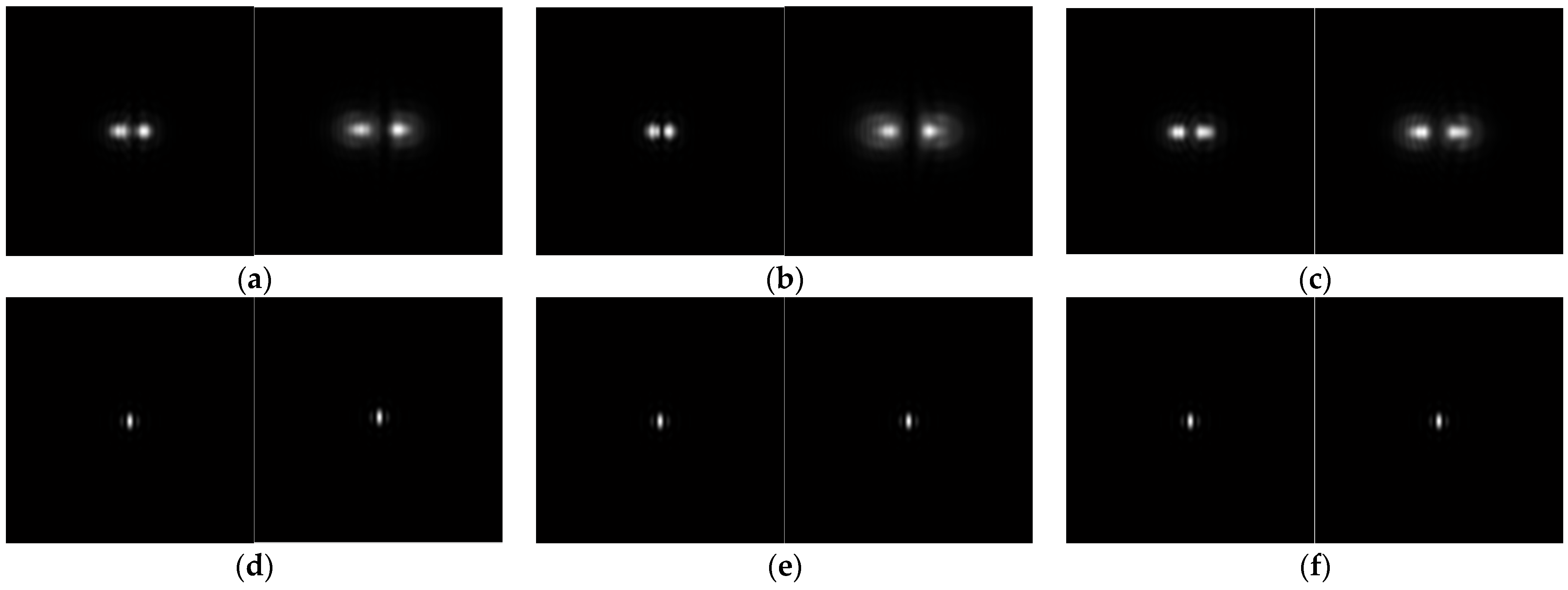
4.1. Piston Detection of Monochromatic Light Conditions

To conduct the numerical simulation and verify the effectiveness of the proposed algorithm improvements, a dual-aperture OSAS was established, as shown in Figure 3, where the diameter of the sub-aperture (D) was 30 mm, the length of the baseline (l) was 33 mm, the focal length (f) was 815 mm, and λ was 632.8 nm.
To avoid the effect of randomness, three groups of actual co-phase errors were chosen randomly at the initial time: the piston error (a), the first defocus error (Δz1), and the second defocus error (Δz2), as listed in Table 1. Then, the objective function established by Equation (23) was solved thirty times using the PSO-SQP algorithm. In addition, the multi-island genetic algorithm (MIGA) [27] and PSO were also used to compare with the proposed algorithm.
To evaluate the effect of piston detection, the root mean square error (RMSE) is defined as follows:
R M S E = ( a a r ) 2 + ( Δ z 1 Δ z 1 r ) 2 + ( Δ z 2 Δ z 2 r ) 2 3   ,
where ar is the actual piston error, Δz1r is the first actual defocus error, and Δz2r is the second actual defocus error. Figure 4 shows the RMSE comparison of the MIGA, PSO, and PSO-SQP algorithms. Figure 5 shows the PSF images before and after detection and correction of co-phase errors of the dual-aperture OSAS using the PSO-SQP algorithm.
According to Figure 4, both MIGA and PSO were unstable, although PSO was better than MIGA, and the maximum RMSE was approximately 0.1λ in the process of achieving thirty solutions, which does not meet the requirements of practical imaging. The RMSE solved by the PSO-SQP algorithm was guaranteed to be within 0.001λ, and the sensing accuracy of the co-phase error greatly improved compared with that of MIGA and PSO, which demonstrates the effectiveness of the proposed hybrid optimization algorithm.

4.2. Piston Detection of Polychromatic Light Conditions

To verify the effectiveness of the improved PD method in the detection of the co-phase error under polychromatic light conditions, a numerical simulation was conducted for the OSAS, as shown in Figure 3. The simulated illumination wavelength was 380–780 nm and the central wavelength was 580 nm. It is assumed that each wavelength component in the broadband was uniformly distributed.
The actual co-phase errors were the same as the monochromatic light conditions, as listed in Table 1. The traditional PD method was used to obtain the objective function shown in Equation (7) and the improved PD method was used to obtain the objective function shown in Equation (23). Subsequently, the PSO-SQP algorithm was used to optimize these two objective functions separately.
Figure 6 shows the RMSE of three groups of simulations using various PD methods based on the PSO-SQP algorithm. Figure 7 shows the PSF images before and after detection and correction of co-phase errors of the dual-aperture OSAS using the PSO-SQP algorithm.
According to Figure 6, the maximum RMSE of the traditional PD method was approximately 0.25λ, which does not meet the requirements of practical imaging. The RMSE using the improved PD method based on the PSO-SQP algorithm was guaranteed to be within 0.001λ and the sensing accuracy of the co-phase error greatly improved compared to the traditional PD method based on the PSO-SQP algorithm, which demonstrates the effectiveness of the improved PD method proposed in this paper.

5. Experimental Test

To demonstrate the performance of the improved PD method based on the PSO-SQP algorithm, a test system mainly composed of a He-Ne laser, two off-axis parabolic mirrors, two right-angle prisms, a convergent lens, a high precision parallel manipulator, and a CCD was constructed, as shown in Figure 8. The red lines with arrows in Figure 8 represent the optical path. The entire test system was placed on an air floating vibration isolation platform to reduce the influence of environmental disturbance on the test results.
After light from the laser was divided into two beams by the first right-angle prism, the two sub-apertures of the dual-aperture OSAS converted spherical waves into parallel light. Then, the light propagation direction was changed by the second right-angle prism. After the two beams of light passed through the convergent lens, they were finally interferometrically imaged on the CCD. There was a translation adjustment mechanism under the convergent lens, which changed the position of the lens to obtain two images at different defocus positions required by the improved PD method. There was a high precision parallel manipulator with a parallel plate on its mobile platform acting as the piston error adjustment mechanism between the sub-aperture and the second right-angle prism. When the parallel manipulator drove the parallel plate to rotate, the incident angle of the beam entering the parallel plate changed, and the optical path length of the beam in the parallel plate changed accordingly. The optical path length introduced by the parallel plate could correct the piston error between sub-apertures. Figure 9 shows the relationship between the rotation angle (θ) of the parallel plate and the compensated piston error (a).
The parameters of the test system are listed in Table 2, where s is the pixel size of the CCD and rθ is rotational repetitive positioning precision of the high precision parallel manipulator.
The experimental test process is shown in Figure 10. To detect and correct the unknown piston error between two sub-apertures, images on two unknown defocus positions were obtained first, as shown in Figure 11. Then, the objective function was obtained using the improved PD method and solved using the PSO-SQP algorithm. Finally, a, Δz1, and Δz2 were calculated to be 0.4098λ, 0.2389λ, and 0.0837λ, respectively.
After the co-phase error was obtained, it was corrected by the defocus error adjustment mechanism and the piston error adjustment mechanism, and then the recovered image was received by the CCD, as shown in Figure 12. Compared with the two images in Figure 11, the recovered image exhibited better interference fringes and contrast, with two side lobes distributed symmetrically. The RMSE of the residual error of the recovered image was 0.0074λ, which indicated the success of piston error detection and correction. The main error sources of the test included residual disturbances after vibration isolation of the air floating platform, environmental air flow, environmental stray light, surface errors of optical components, and correction residual of co-phase error adjustment mechanisms.

6. Discussion

Table 3 and Table 4 show the average values of RMSE after thirty calculations using different methods under the monochromatic and polychromatic light conditions in Section 4, respectively. The improved PD method based on the PSO-SQP algorithm proposed in this paper outperforms other methods in different situations. In Section 5, the experimental results showed that the imaging quality of the dual-aperture OSAS under monochromatic light was significantly improved after co-phase error detection and correction using the method proposed in this paper. The effectiveness of the improved PD method based on the PSO-SQP algorithm has been comprehensively verified by simulation and experiment.
In terms of the sensing accuracy of the piston error and the computation time, it is necessary to compare the method proposed in this paper with the convolutional neural network methods widely used in recent years. Taking the convolutional neural network based on ResNet-34 proposed by Wang [28] as an example, in terms of sensing accuracy, the average RMSE of a Golay-6 OSAS was less than 0.015λ; in terms of computation time, a solution took about 88 ms with the Intel Core Processor CPU (2.3 GHz) and NVIDIA GeForce RTX3060 GPU, but the early training time was about 172 min. In terms of sensing accuracy, the RMSE of the proposed method of a dual-aperture OSAS was less than 0.001λ; in terms of computation time, it took about 154 s and 409 s to solve once for monochromatic and polychromatic light conditions with the Intel Core Processor CPU (2.7 GHz) and NVIDIA GeForce RTX3050 GPU.

7. Conclusions

In this paper, an improved PD method based on the PSO-SQP algorithm was proposed to detect the piston error of the OSAS. The objective function was obtained using the improved PD method with images at two defocus positions, and the PSO-SQP algorithm was subsequently performed to calculate the two unknown defocus errors and the piston error. This piston detection method has the advantages of a simple optical system, wide range of application, high detection accuracy, and high solution stability. A dual-aperture OSAS simulation platform was built and numerical simulations of monochromatic light illumination and polychromatic light illumination were conducted. The simulation results showed that the RMSE using the improved PD method based on the PSO-SQP algorithm was guaranteed to be within 0.001λ, which satisfies the requirement of practical imaging. A piston error detection and correction experiment was conducted based on a dual-aperture OSAS. The recovered image exhibited better interference fringes and contrast than images with the co-phase error, which further demonstrated the reliability of the improved PD method based on the PSO-SQP algorithm. Future research will focus on co-phase error detection and correction, including the tip/tilt error.

Author Contributions

Conceptualization, Q.W., Z.X. and Y.Z.; methodology, Y.Z., J.L. and X.T.; software, Y.Z., J.L., T.L. and X.T.; validation, Y.Z., J.L. and T.L.; formal analysis, Y.Z., J.L. and T.L.; investigation, Q.W., Z.X. and Y.Z.; resources, Q.W., Z.X. and X.T.; data curation, Y.Z., J.L and T.L.; writing—original draft preparation, Y.Z., J.L. and T.L.; writing—review and editing, Q.W., Z.X. and X.T.; visualization, Y.Z. and J.L.; supervision, Q.W., Z.X. and Y.Z.; project administration, Q.W., Z.X. and Y.Z.; funding acquisition, Q.W. and Z.X. All authors have read and agreed to the published version of the manuscript.

Funding

This research was funded by the National Natural Science Foundation of China (grant numbers 61705223 and 62235018).

Institutional Review Board Statement

Not applicable.

Informed Consent Statement

Not applicable.

Data Availability Statement

Not applicable.

Acknowledgments

The authors would like to express our sincere gratitude to Key Laboratory of On-orbit Manufacturing and Integration for Space Optics System, Chinese Academy of Sciences for providing an experimental site and equipment.

Conflicts of Interest

The authors declare no conflict of interest.

References

  1. Yang, L.; Yang, D. Co-phase state detection for segmented mirrors by dual-wavelength optical vortex phase-shifting interferometry. Opt. Express 2022, 30, 14088–14102. [Google Scholar] [CrossRef]
  2. Aden, B.M.; Marjorie, P.M. Large sparse-aperture space optical systems. Opt. Eng. 2002, 41, 1983–1994. [Google Scholar]
  3. Wang, D.; Ji, H. Experimental study on imaging and image restoration of optical sparse aperture systems. Opt. Eng. 2007, 46, 103201. [Google Scholar] [CrossRef]
  4. Gardner, J.P.; Mather, J.C. The James Webb space telescope. Space Sci. Rev. 2006, 123, 485–606. [Google Scholar] [CrossRef]
  5. Spano, P.; Zerbi, F.M. Challenges in optics for Extremely Large Telescope instrumentation. Astron. Nachr. 2010, 327, 649–673. [Google Scholar] [CrossRef]
  6. Hill, J.M. The Large Binocular Telescope. Appl. Opt. 2010, 49, D115–D122. [Google Scholar] [CrossRef] [PubMed]
  7. Trumper, I.; Hallibert, P.A. Optics technology for large-aperture space telescopes: From fabrication to final acceptance tests. Adv. Opt. Photonics 2018, 10, 644–702. [Google Scholar] [CrossRef]
  8. Li, X.; Yang, X. The piston error recognition technique used in the modified Shack–Hartmann sensor. Opt. Commun. 2021, 501, 127388. [Google Scholar] [CrossRef]
  9. Larkin, J.E.; Glassman, T.M. Exploring the structure of distant galaxies with adaptive optics on the Keck II Telescope. Publ. Astron. Soc. Pac. 2000, 112, 1526–1531. [Google Scholar] [CrossRef]
  10. Haffert, S.Y.; Close, L.M. Phasing the Giant Magellan Telescope with the holographic dispersed fringe sensor. J. Astron. Telesc. Inst. 2022, 8, 021513. [Google Scholar] [CrossRef]
  11. Esposito, S.; Pinna, E. Pyramid sensor for segmented mirror alignment. Opt. Lett. 2005, 30, 2572–2574. [Google Scholar] [CrossRef] [PubMed]
  12. Deprez, M.; Bellanger, C. Piston and tilt interferometry for segmented wavefront sensing. Opt. Lett. 2016, 41, 1078–1081. [Google Scholar] [CrossRef] [PubMed]
  13. Qin, S.; Chan, W.K. A Tip–Tilt and Piston Detection Approach for Segmented Telescopes. Photonics 2020, 8, 3. [Google Scholar] [CrossRef]
  14. Vievard, S.; Cassaing, F. Large amplitude tip/tilt estimation by geometric diversity for multiple-aperture telescopes. J. Opt. Soc. Am. A 2017, 34, 1272–1284. [Google Scholar] [CrossRef] [PubMed]
  15. Mourard, D.; Dali, A.W. Group and phase delay sensing for cophasing large optical arrays. Mon. Not. R. Astron. Soc. 2014, 445, 2082. [Google Scholar] [CrossRef]
  16. Simar, J.F.; Stockman, Y. Single-wavelength coarse phasing in segmented telescopes. Appl. Opt. 2015, 54, 1118–1123. [Google Scholar] [CrossRef]
  17. Jiang, J.; Zhao, W. Phasing piston error in segmented telescopes. Opt. Express 2016, 24, 19123–19137. [Google Scholar] [CrossRef] [PubMed]
  18. Zhao, W.; Zeng, Q. Simultaneous multi-piston measurement method in segmented telescopes. Opt. Express 2017, 25, 24540–24552. [Google Scholar] [CrossRef]
  19. Xie, Z.; Ma, H. Adaptive piston correction of sparse aperture systems with stochastic parallel gradient descent algorithm. Opt. Express 2018, 26, 9541–9551. [Google Scholar] [CrossRef]
  20. Lamb, M.P.; Correia, C. Quantifying telescope phase discontinuities external to adaptive optics systems by use of phase diversity and focal plane sharpening. J. Astron. Telesc. Inst. 2017, 3, 039001. [Google Scholar] [CrossRef]
  21. Li, C.C.; Yan, F.T. Cophasing detection of the segmented diffractive optical elements with the phase diversity method. Opt. Eng. 2022, 61, 123105. [Google Scholar] [CrossRef]
  22. Campbell, H.I.; Zhang, S. Generalized phase diversity for wave-front sensing. Opt. Lett. 2004, 29, 2707–2709. [Google Scholar] [CrossRef] [PubMed]
  23. Bolcar, M.R.; Fienup, J.R. Sub-aperture piston phase diversity for segmented and multi-aperture systems. Appl. Opt. 2009, 48, A5. [Google Scholar] [CrossRef] [PubMed]
  24. Yann, C.M.; Clerc, P.S. Performance evaluation of TRIBES, an adaptive particle swarm optimization algorithm. Swarm Intell. 2009, 3, 149–178. [Google Scholar]
  25. Sun, Z.B.; Sun, Y.Y. A new trust region-sequential quadratic programming approach for nonlinear systems based on nonlinear model predictive control. Eng. Optim 2019, 51, 1071–1096. [Google Scholar] [CrossRef]
  26. Kennedy, J.; Eberhart, R. Particle swarm optimization. In Proceedings of the IEEE International Conference on Neural Networks, New York, NY, USA, 27 November–1 December 1995; pp. 1942–1948. [Google Scholar]
  27. Wang, J.; Wang, C. Airfoil shape and angle of attack optimization based on bézier curve and multi-island genetic algorithm. J. Fluid Eng. 2022, 144, 051203. [Google Scholar] [CrossRef]
  28. Wang, S.M.; Wu, Q.Y. Piston sensing for Golay-6 sparse aperture system with double-defocused sharpness metrics via ResNes-34. Sensors 2022, 22, 9484. [Google Scholar] [CrossRef]
Figure 1. Optical path of the PD method used in the OSAS.
Photonics 10 01039 g001
Figure 2. Flow chart of the PSO-SQP algorithm applied in the OSAS.
Photonics 10 01039 g002
Figure 3. Sub-aperture arrangement.
Photonics 10 01039 g003
Figure 4. RMSE of three groups of simulation examples using various optimization algorithms: (a) the first group; (b) the second group; and (c) the third group.
Photonics 10 01039 g004
Figure 5. PSF images of the dual-aperture OSAS under monochromatic light conditions: (a) distorted PSF of the first group; (b) distorted PSF of the second group; (c) distorted PSF of the third group (d) corrected PSF of the first group; (e) corrected PSF of the second group; and (f) corrected PSF of the third group.
Photonics 10 01039 g005
Figure 6. RMSE of three groups of simulation examples using various PD methods: (a) the first group; (b) the second group; and (c) the third group.
Photonics 10 01039 g006
Figure 7. PSF images of the dual-aperture OSAS under polychromatic light conditions: (a) distorted PSF of the first group; (b) distorted PSF of the second group; (c) distorted PSF of the third group (d) corrected PSF of the first group; (e) corrected PSF of the second group; and (f) corrected PSF of the third group.
Photonics 10 01039 g007
Figure 8. Experimental setup.
Photonics 10 01039 g008
Figure 9. Curve of the relationship between the rotation angle of the parallel plate and the compensated piston error.
Photonics 10 01039 g009
Figure 10. Flow chart of piston error correction for the dual-aperture OSAS.
Photonics 10 01039 g010
Figure 11. CCD images before co-phase error detection and correction: (a) the first defocused position; and (b) the second defocused position.
Photonics 10 01039 g011
Figure 12. CCD image after co-phase error detection and correction.
Photonics 10 01039 g012
Table 1. The actual co-phase errors of the dual-aperture OSAS.
Design VariablesGroup 1Group 2Group 3
a(λ)Δz1(λ)Δz2(λ)a(λ)Δz1(λ)Δz2(λ)a(λ)Δz1(λ)Δz2(λ)
Actual co-phase errors0.24750.56471.02450.51240.35751.24550.82870.63250.9874
Table 2. Parameters of the test system.
ParameterλfDlsrθ
Unitnmmmmmmmμm°
Value632.881530331.40.0024
Table 3. The average value of RMSE for different methods under monochromatic light conditions.
MethodsAverage Value of RMSE (λ)
Group 1Group 2Group 3
Improved PD based on MIGA0.04820.04270.0413
Improved PD based on PSO0.02020.02800.0313
Improved PD based on PSO-SQP0.00030.00030.0005
Table 4. The average value of RMSE for different methods under polychromatic light conditions.
MethodsAverage Value of RMSE (λ)
Group 1Group 2Group 3
Traditional PD based on PSO-SQP0.02300.03160.0365
Improved PD based on PSO-SQP0.00030.00040.0004
Disclaimer/Publisher’s Note: The statements, opinions and data contained in all publications are solely those of the individual author(s) and contributor(s) and not of MDPI and/or the editor(s). MDPI and/or the editor(s) disclaim responsibility for any injury to people or property resulting from any ideas, methods, instructions or products referred to in the content.

