Article

Terahertz Radiation from High Electron Mobility Avalanche Transit Time Sources Prospective for Biomedical Spectroscopy

1
Department of Electronics & Communication Engineering, National Institute of Technology Mizoram, Chaltlang, Aizawl 796012, Mizoram, India
2
Department of Electronics and Communication Engineering, Cooch Behar Government Engineering College, Harinchawra, Ghughumari, Cooch Behar 736170, West Bengal, India
3
Research Institute of Electronics, Shizuoka University, Hamamatsu 4328011, Japan
4
Centre for IoT and AI Integration with Education-Industry-Agriculture, Department of Mining Engineering, Kazi Nazrul University, Asansol 713340, West Bengal, India
5
Microsystem Design-Integration Lab, Physics Department, Bidhan Chandra College, Asansol 713303, West Bengal, India
6
Immanuel Kant Baltic Federal University, 236000 Kaliningrad, Russia
7
Amur State University, 675027 Blagoveshchensk, Russia
*
Authors to whom correspondence should be addressed.
Photonics 2023, 10(7), 800; https://doi.org/10.3390/photonics10070800
Submission received: 29 May 2023 / Revised: 27 June 2023 / Accepted: 6 July 2023 / Published: 10 July 2023
(This article belongs to the Special Issue Biomedical Spectroscopy: Techniques and Applications)

Abstract

:
A Schottky barrier high-electron-mobility avalanche transit time (HEM-ATT) structure is proposed for terahertz (THz) wave generation. The structure is laterally oriented and based on AlGaN/GaN two-dimensional electron gas (2-DEG). Trenches are introduced at different positions of the top AlGaN barrier layer for realizing different sheet carrier density profiles at the 2-DEG channel; the resulting devices are equivalent to high–low, low–high and low-high–low quasi-Read structures. The DC, large-signal and noise simulations of the HEM-ATTs were carried out using the Silvaco ATLAS platform, non-sinusoidal-voltage-excited large-signal and double-iterative field-maximum small-signal simulation models, respectively. The breakdown voltages of the devices estimated via simulation were validated by using experimental measurements; they were found to be around 17–18 V. Under large-signal conditions, the series resistance of the device is estimated to be around 20 Ω. The large-signal simulation shows that the HEM-ATT source is capable of delivering nearly 300 mW of continuous-wave peak power with 11% conversion efficiency at 1.0 THz, which is a significant improvement over the achievable THz power output and efficiency from the conventional vertical GaN double-drift region (DDR) IMPATT THz source. The noise performance of the THz source was found to be significantly improved by using the quasi-Read HEM-ATT structures compared to the conventional vertical Schottky barrier IMPATT structure. These devices are compatible with the state-of-the-art medium-scale semiconductor device fabrication processes, with scope for further miniaturization, and may have significant potential for application in compact biomedical spectroscopy systems as THz solid-state sources.

1. Introduction

Recently, the frequency gap between the millimeter-wave and infrared bands, known as the terahertz gap (THz-gap), is drawing the attention of researchers due to its enormous possible applications in the fields of imaging, astronomy and spectroscopy; the quality inspection of industrial, medical and pharmaceutical products; in bio-sensing; etc. [1,2,3,4,5,6,7,8]. Some solid-state devices such as high-electron-mobility transistors (HEMTs), heterojunction bipolar transistors (HBTs), quantum cascade lasers (QCLs), impact avalanche transit time (IMPATT) diodes, resonant tunneling diodes (RTDs), etc., have shown excellent possibilities for generating and detecting THz waves in the recent past [9,10,11,12,13,14,15,16,17,18,19,20,21,22,23,24]. Out of all possible solid-state THz sources, IMPATT diodes based on wide-bandgap materials such as GaN, SiC, etc., have emerged as the most powerful with regard to THz power output and DC to THz conversion efficiency [23,24]. The superior electronic and thermal properties of GaN establish it as the most suitable material for fabricating high-power, high-efficiency THz IMPATT sources. However, the most significant obstruction against the conventional vertical single-drift region (SDR: p+-n-n+ or n+-p-p+) and double-drift-region (DDR: p+-p-n-n+) IMPATT sources for THz wave generation is the high contact resistivity of the metal~p+-GaN ohmic contact. So far as the authors’ knowledge is concerned, the lowest experimentally achieved contact resistivity of metal~p+GaN contact is 1.0 Ω cm [25,26], which is significantly high. As a result, the parasitic series resistance of the SDR and DDR GaN IMPATT rises with relation to the diode negative resistance in the THz regime [27]. Significantly high series resistance at THz frequencies is the primary limitation against the possibilities of obtaining THz power from GaN IMPATT sources. One probable solution is to use the edge-terminated reverse IMPATT structure, in which the cross-sectional area of the metal~p+-GaN contact is increased in order to reduce the contact resistance [28]. However, several issues related to the fabrication of said structure may arise during practical realization [28]. Therefore, in order to avoid the parasitic effects of the metal~p+-GaN contact in the IMPATT diode structure for THz wave generation, a Schottky barrier IMPATT structure, an alternative to GaN SDR or DDR IMPATT, is recommended [29,30]. Moreover, the lateral orientation of the proposed structures possesses an additional advantage over the conventional vertically oriented IMPATT structures. Monolithic integration of these lateral structures by using state-of-the-art complementary metal–insulator–semiconductor (CMOS) technology is possible in near future, while the vertical IMPATT structures do not support CMOS integration.
The high spontaneous as well as piezoelectric polarization effects in the two-dimensional electron gas (2-DEG) at the AlGaN/GaN interface leads to the excellent THz performance of HEMT devices [31]. Significantly better electron mobility can be achieved in 2-DEG AlGaN/GaN HEMT structures compared to in the bulk GaN [32,33]. Therefore, if this HEMT structure based on AlGaN/GaN 2-DEG can be combined with the Schottky barrier SDR avalanche transit time (ATT) structure, then the resulting structure can utilize the THz potentialities of both HEMT and ATT structures; this blending of HEMT and ATT structures was first proposed and investigated by Zhang et al. in the year 2022 [34]. In this article, a quasi-Read Schottky barrier lateral HEM-ATT structure based on AlGaN/GaN 2-DEG is proposed for generating a 1.0 THz frequency. One and more than one trenches were introduced at different positions of the top AlGaN layer in order to realize different quasi-Read carrier density profiles at the 2-DEG channel region such as high–low (hi-lo), low–high (lo-hi) and low-high–low (lo-hi-lo). The static or DC simulation of HEM-ATTs was carried out by using the Silvaco ATLAS device simulation platform, whereas the THz and noise performances of the device were investigated by using a natively developed non-sinusoidal-voltage-excited (NSVE) large-signal model and double-iterative field maximum (DEFM) small-signal model, respectively. The DC simulation reveals that the breakdown of all the devices occurs nearly at 17 V. A maximum series resistance of around 20 Ω was found to be present in the device under large-signal operating conditions. The large-signal simulation shows that the HEM-ATT source is capable of delivering nearly 300 mW of continuous peak power with 11% conversion efficiency at 1.0 THz, which is a significant improvement compared to the achievable THz power output and efficiency from the conventional THz DDR IMPATT source. The noise performance of the THz source was found to be significantly improved by using the quasi-Read HEM-ATT structures compared to the conventional vertically oriented Schottky barrier IMPATT structure. By lateral integration of multiple HEM-ATT diodes, an oscillator array can be realized on the monolithic integrated circuit in order to implement a broadband THz source. Moreover, a third terminal (gate) can be included over the AlGaN layer for directly modulating power and frequency via an externally applied signal. In the proposed HEM-ATT structures, optical signal coupling and injection locking are also very much convenient through the thin AlGaN layer.

2. Prospect of Terahertz Biomedical Spectroscopy

Currently, there is enormous interest in the application of Terahertz waves (THz~300 GHz to 3 THz; wavelength: 100 μm to 1 mm), particularly around 1 THz, that can yield extremely high-resolution images, useful for non-contact, non-destructive sensing. Terahertz waves are best suited for biomedical spectroscopy as they do not induce any destructive chemical reactions in human tissue [35]. THz comes with the unique capability of detecting weak inter-molecule coupling, and hence identifying associated molecular networks, useful for biomedical spectroscopy and diagnosis (e.g., tooth decay, skin cancer, tumors protein, DNA, gene etc.) [36,37,38,39,40,41]. While the prospect of medical application of Terahertz waves is exciting, the current state of THz technology is still inadequate in providing compact, powerful sources and efficient detectors for detection systems technologically compatible with medical spectroscopy applications, particularly at room temperature. Technological advances in material sciences and microfabrication and device technologies in the last decade have facilitated the development of powerful sources, uncooled detectors and advanced imaging techniques, along with an extended scope for flexible electronics; biomedical, high-frequency sensing (particularly promising); and communication devices [42,43,44]. A few of the remarkable advancements in recent times leading the prospective application of THz in biomedical spectroscopy include [45,46]: THz wound and diabetic injury screening [47]; spectroscopy and imaging for cancer diagnosis [48,49,50]; a THz time-domain spectral (THz-TDS) system for biological macromolecule detection [51]; biomolecular and pathogen detection [52] and evaluation of transdermal drug delivery [53]; identification of tumor mutation in the central nervous system [54,55]; and intraoperative neurodiagnostics [56]. Further advancement in THz biophotonics, materials and instrumentation [57,58,59]; tissue imaging techniques [60,61,62]; and applied computing algorithms [63] may also open up newer frontiers in THz biomedical applications. In the current work, the possibility of a compact yet powerful solid-state THz source promising for biomedical spectroscopy applications is reported.

3. Device Structure and Fabrication

The cross-sectional views of the proposed Schottky barrier lateral HEM-ATT structure having flat, hi-lo, lo-hi and lo-hi-lo carrier density profiles are illustrated in Figure 1a–d, respectively. An unintentionally doped Al0.2Ga0.8N barrier layer of the thickness of 20 nm can be grown on the undoped GaN buffer layer in order to form the AlGaN/GaN based HEM-ATT structure. The 2-DEG formed below the AlGaN/GaN interface (channel region) results in impurities scattering the free transport of electrons through the bound states of the triangle quantum well. The length of the channel region was kept at Ld = 200 nm for the 1.0 THz operation of the device. The Schottky contact was formed at the anode side by using Ni (work function = 5.15 eV) deposition as shown in Figure 2a–d. The complete anode contact was formed by Ni (20 nm thick)/Au (100 nm thick) with a total height of 40 nm. On the right-hand side, first a 40 nm high, 100 nm thick n+-GaN (donor concentration = 4.00 × 1024 m−3) layer was formed, after which Ti (30 nm thick)/Au (150 nm thick) ohmic contact of the same height (40 nm) was deposited in order to realize the cathode contact. The width of the device (Wd) was set as 50 nm for supplying high DC bias current density of the order of 10−9 A m−2. The structure shown in Figure 1a is basically a Schottky barrier SDR HEM-ATT diode.
It is primarily the free electrons in the AlGaN barrier layer and GaN buffer layer that accumulate at the triangular shaped potential well in the GaN buffer layer close to the AlGaN/GaN interface due to the spontaneous and piezoelectric-polarization-induced electric fields in AlGaN and GaN. The bound state in the triangular quantum well in the GaN buffer layer close to the AlGaN/GaN interface is occupied by these accumulated electrons and forms the 2-DEG channel region (those electrons are confined along y- and z-directions). These 2-DEG electrons have significantly higher mobility along the x-direction in comparison to the electrons in the bulk GaN-buffer layer, since the 2-DEG electrons are spatially separated from the immobile space charges primarily present in the AlGaN-barrier and GaN buffer layers (free from impurity scattering) [64]. The improved mobility of the carriers (electrons) in HEM-ATT makes it superior to the normal vertically oriented Schottky barrier and p-n junction based SDR (p+-n-n+ or n+-p-p+) IMPATTs. Moreover, Schottky barrier HEM-ATT can avoid the parasitic series resistance caused by un-depleted p- and p+-layers, which are unavoidable in p-n junction based SDR and DDR structures.
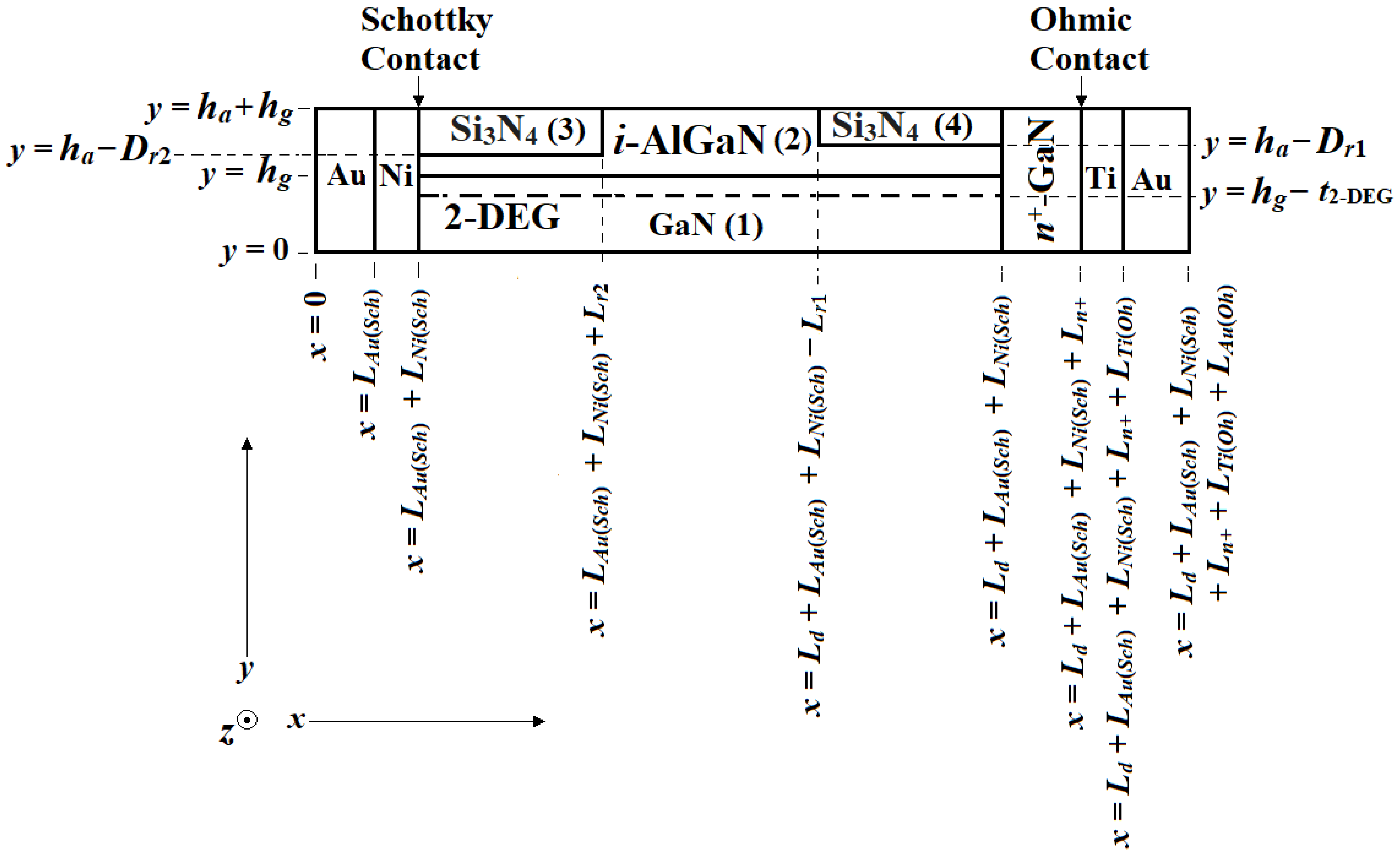
The unintentionally doped AlGaN barrier layer is the primary injector of 2-DEG electrons. Thus, a greater thickness of AlGaN layer causes a larger number of electrons to accumulate in the 2-DEG channel region (resulting in a larger sheet of electron concentration); similarly, the smaller the thickness of the AlGaN barrier layer, the smaller the sheet electron concentration in the 2-DEG channel [64,65]. Therefore, the sheet electron concentration in 2-DEG can be modulated by changing the thickness of the AlGaN-barrier layer [64,65]. By introducing a trench of finite length and depth (Figure 1b,c), i.e., by reducing the thickness of the AlGaN barrier at a particular region, the sheet electron concentration of the channel just below that region can be decreased without altering the sheet electron concentration throughout the rest of the channel region. Depending on the position of the trench (see Figure 1b,c), hi-lo and lo-hi sheet electron density profiles can be created. Similarly, by using two trenches (Figure 1d), a lo-hi-lo sheet electron density profile can be achieved. These quasi-Read electron density profiles were used to narrow down the avalanche region width of millimeter-wave and THz ATT devices, which resulted in a significant increase in DC to RF conversion efficiency and noteworthy improvement in the avalanche noise performance of the source [66,67]. The said trench or trenches of height Dr1,2 = 10 nm and length Lr1,2 = 50 nm can be formed at the top of the AlGaN barrier layer at the desired position by using the appropriate reactive ion etching (RIE) technique. Figure 1b–d show the hi-lo, lo-hi and lo-hi-lo quasi-Read HEM-ATT structures, respectively. The structural parameters of the four types of HEM-ATT diodes are listed in Table 1.
The starting material for the fabrication of the proposed structure is an n-type GaN substrate with a 400 nm thick undoped GaN buffer layer grown using the metal–organic chemical vapor deposition (MOCVD) technique. The 20 nm thick Al0.2Ga0.8N barrier layer was then grown on the n-GaN buffer layer by using the same MOCVD apparatus. Ideally, the AlGaN layer should be undoped; practically, this layer is unintentionally doped. After the formation of the top AlGaN layer, a SiO2 hard mask may be deposited over it. Appropriate masking and electron-beam lithography techniques were used to open the window for the Si ion implementation to form the n+-GaN layer (with the resulting doping concentration of 4.0 × 1024 m−3). Around 40 nm of AlGaN/GaN has to be etched away via Cl2-based inductively coupled plasma reactive ion etching (ICP-RIE) with a moderate etching rate in order to form the well for forming the Schottky contact. The oblique vacuum evaporation of Ni (20 nm) followed by Au (100 nm) was performed sequentially to form the Ni/Au Schottky contact on the anode side. After that, another masking step followed by the same Cl2-based ICP-RIE and vacuum evaporation of Ti (30 nm) and Au (150 nm) in the reverse direction were applied to form the ohmic contact at the cathode side. Nitrogen ion implantation (N+-ion implantation) based edge-termination technology was introduced to form a highly resistive layer outside of the active device area to laterally isolate the device and prevent electric field crowding and consequent premature breakdown under the reverse bias condition (edge-termination is not shown in Figure 1a–d.

4. Simulation Method

The steady-state DC simulation was performed using the Silvaco-ATLAS platform. The DC parameters of a HEM-ATT device for a given current density were obtained by solving a time-independent Poisson equation, carrier continuity equations and current density equations subject to appropriate boundary conditions. The simulations were carried out by assuming the junction temperature of the device is same as the ambient temperature (i.e., 300 K). The 2-DEG electron concentration was estimated by using the knowledge of the polarization-induced sheet charge density [68]. The AlGaN/GaN interface charges were also taken into consideration while calculating the polarization-induced 2-DEG electron concentration. The maximum sheet carrier concentration at the undoped AlGaN/GaN interface may be defined as
n s x = + σ x q ϵ 0 ϵ r x d q 2 q Φ b x + E F x Δ E c x
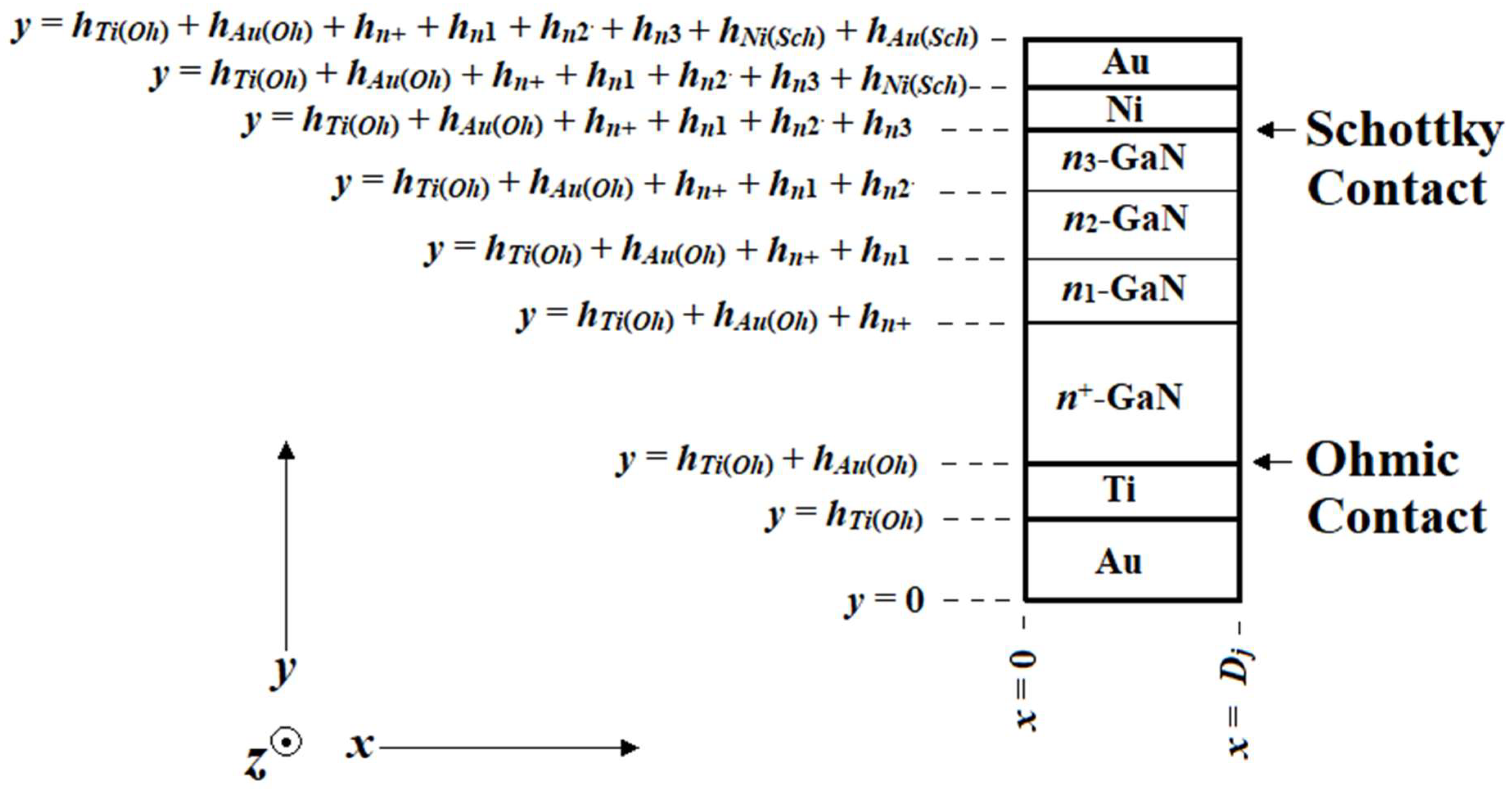
where d is the thickness of AlGaN layer, σ is the polarization-induced sheet charge concentration, ϵ r x is the space-dependent relative permittivity, ϵ 0 = 8.854 × 10⁻¹² F m−1 is the permittivity in vacuum, q = 1.6 × 10⁻¹⁹ C is the charge of the electron, EF is the Fermi energy level, ΔEc is the conduction band offset voltage and b is the Schottky barrier. The value of the local maximum sheet carrier concentration at the AlGaN/GaN interface depends on the thickness of the AlGaN layer [64,65,69]. The HEM-ATT device shown in Figure 1a does not have any trench; this device forms the classical SDR flat concentration profile in the 2-DEG channel. However, due to the existence of one trench at different positions, the HEM-ATT devices shown in Figure 1b,c form classical SDR hi-lo and lo-hi concentration profiles in the respective 2-DEG channel regions. On the other hand, the HEM-ATT structure illustrated in Figure 1d forms a lo-hi-lo concentration profile at the 2-DEG channel region due to the existence of two trenches. The generalized (lo-hi-lo) two-dimensional (2D) model for simulating the lateral Schottky barrier HEM-ATT structures is shown in Figure 2. The regions 1 and 2 correspond to the GaN buffer and AlGaN barrier layers, respectively, and regions 3 and 4 correspond to the Si3N4 passivation layers. For the simulation of a flat-profile HEM-ATT (Figure 1a), both region 3 and region 4 are absent, and the entire region corresponds to region 2 (AlGaN layer), whereas for simulating hi-lo and lo-hi HEM-ATTs (Figure 1b,c, respectively), either region 3 (for hi-lo) or region 4 (for lo-hi) is replaced by region 2. In order to compare the DC, THz and noise performances of the lateral HEM-ATT devices with the conventional vertical Schottky barrier SDR IMPATT and GaN DDR IMPATT diodes, the simulations were also extended for those conventional structures separately. The 2D models for simulating the vertical Schottky barrier SDR IMPATT and GaN DDR IMPATT are shown in Figure 3 and Figure 4, respectively, (both of these having lo-hi-lo doping profiles). The thicknesses of the n+-, n1-, n2- and n3-GaN layers in the vertical Schottky barrier SDR diode (Figure 3) were 100, 50, 100 and 50 nm, respectively, and the corresponding doping concentrations were 4.0 × 1024, 2.0 × 10²³, 6.0 × 10²³ and 2.0 × 10²³ m−3, respectively. The thicknesses of the p+- and p-layers in the GaN DDR structure (Figure 4) are the same as those of the n+- and n-GaN layers, these layers being at 100, 50, 100, 50 nm, respectively; the magnitudes of the doping concentrations are also symmetric and are 4.0 × 1024, 2.0 × 10²³, 6.0 × 10²³ and 2.0 × 10²³ m−3, respectively.
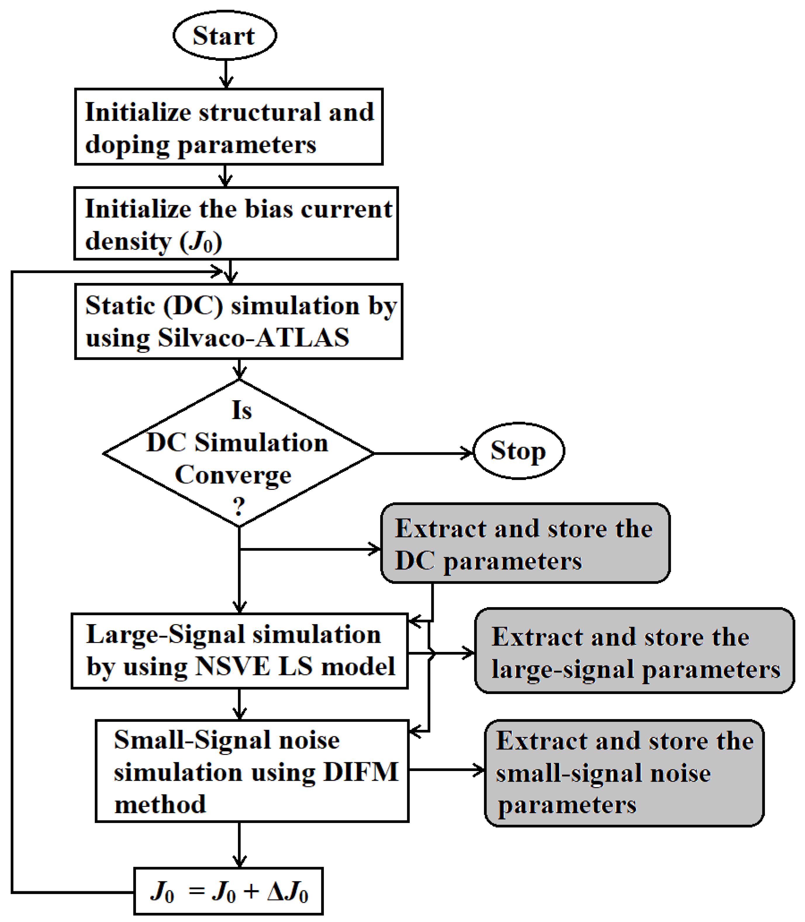
If the DC simulation converged for a given current density value (J0), the output DC parameters such as avalanche width, p- and n-layer drift widths, avalanche voltage, total drift voltage, breakdown voltage, etc., were extracted and stored. Those DC parameters were used as the initial conditions for the large-signal simulation for the same value of J0. A natively developed non-sinusoidal-voltage-excited (NSVE) large-signal model was used to carry out the large-signal simulation [70]. The output of the large-signal simulation for the given J0 was extracted and stored. The important large-signal parameters are time-domain terminal voltage, terminal current waveforms, frequency domain of the diode voltage and current and other parameters such as diode impedance, admittance, negative conductance, susceptance, quality factor, negative resistance, reactance, and series resistance as functions of frequency and current density. After that, the J0 value was updated, and the entire process was repeated until the DC simulation became non-convergent in order to obtain the full-band THz performance of the diode structure. Finally, the RF power output and the DC to RF conversion efficiency at a particular operating frequency (f) for a given J0 can be obtained as
P R F = 1 2 V R F 2 G p
η L = P R F I 0   V B
where VRF is the magnitude of the RF voltage (VRF = mxVB, where mx = 50–60% is the large-signal modulation index and VB is the breakdown voltage), |Gp| is the magnitude of the peak negative conductance and I0 is the DC bias current. The parasitic series resistance arising from the un-depleted channel, n+-GaN layer, Schottky barrier and cathode ohmic contact of the device were calculated by using an earlier reported method based on depletion width modulation phenomena [71] that also takes into account the influence of the skin effect [72].
The random impact ionization process introduces unwanted unsystematic fluctuations in particle current and electric field inside the DC components of an IMPATT device. These unsystematic current and field fluctuations appear as small-signal components to their corresponding steady-state DC values under reverse bias breakdown conditions. The open-circuit condition without any applied high-frequency AC voltage signal was considered for the small-signal avalanche noise simulation [73]. Two second-order differential equations corresponding to the real and imaginary parts of the noise field were simultaneously solved, subject to appropriate boundary conditions, by using the Runge–Kutta method in order to obtain the noise field distribution along the depletion layer [74]. Here, band-to-band tunneling is considered as a noiseless instantaneous process. This noise simulation method is known as the DIFM method [73,74]. Finally, from the knowledge of the mean square noise current and voltage, the transfer noise impedance at each space point of the depletion layer was calculated. Additionally, from the knowledge of the transfer noise impedance distribution along the depletion layer, the mean square noise voltage v n 2 can be obtained, from which the noise spectral density (NSD(f) = v n 2 / d f V2 s) or mean square noise voltage per bandwidth (df) can be obtained as a function of frequency (f). The noise performance of the IMPATT source was assessed by the parameter named noise measure (NM) [74], which is defined as
N M f = NSD f 4 k B T R d f R s
where kB = 1.38 × 10⁻²³ J K−1 is the Boltzmann constant, T = 300 K is the ambient temperature, R d f is the diode negative resistance and R s is the series resistance. Figure 5 illustrates the complete simulation methodology including the DC simulation, large-signal simulation and small-signal noise simulation in a single flowchart form.

5. Steady-State DC Characteristics

The modified drift–diffusion model including the Poisson equation, carrier continuity equation and current density equation was used in the Silvaco ATLAS platform in order to carry out the steady-state DC analysis of the lateral quasi-Read HEM-ATT structures. The effects of concentration and field-dependent mobility (conmob and fldmob), Shockley–Read–Hall and Auger recombinations (srh and auger), band-to-band tunneling (autobbt), trap-assisted tunneling, etc., were included in the simulation. Fermi statistics (fermi) and the effects of band gap narrowing (bgn), interface charges, charge trapping, passivation, mobile space charge, etc., were also considered in the simulation model. Initially, the entire simulation model was calibrated against the experimental data of earlier published reports [75,76]. The same DC simulation study was also repeated for the vertical SDR Schottky barrier and vertical GaN DDR quasi-Read IMPATT structures for the sake of comparison.
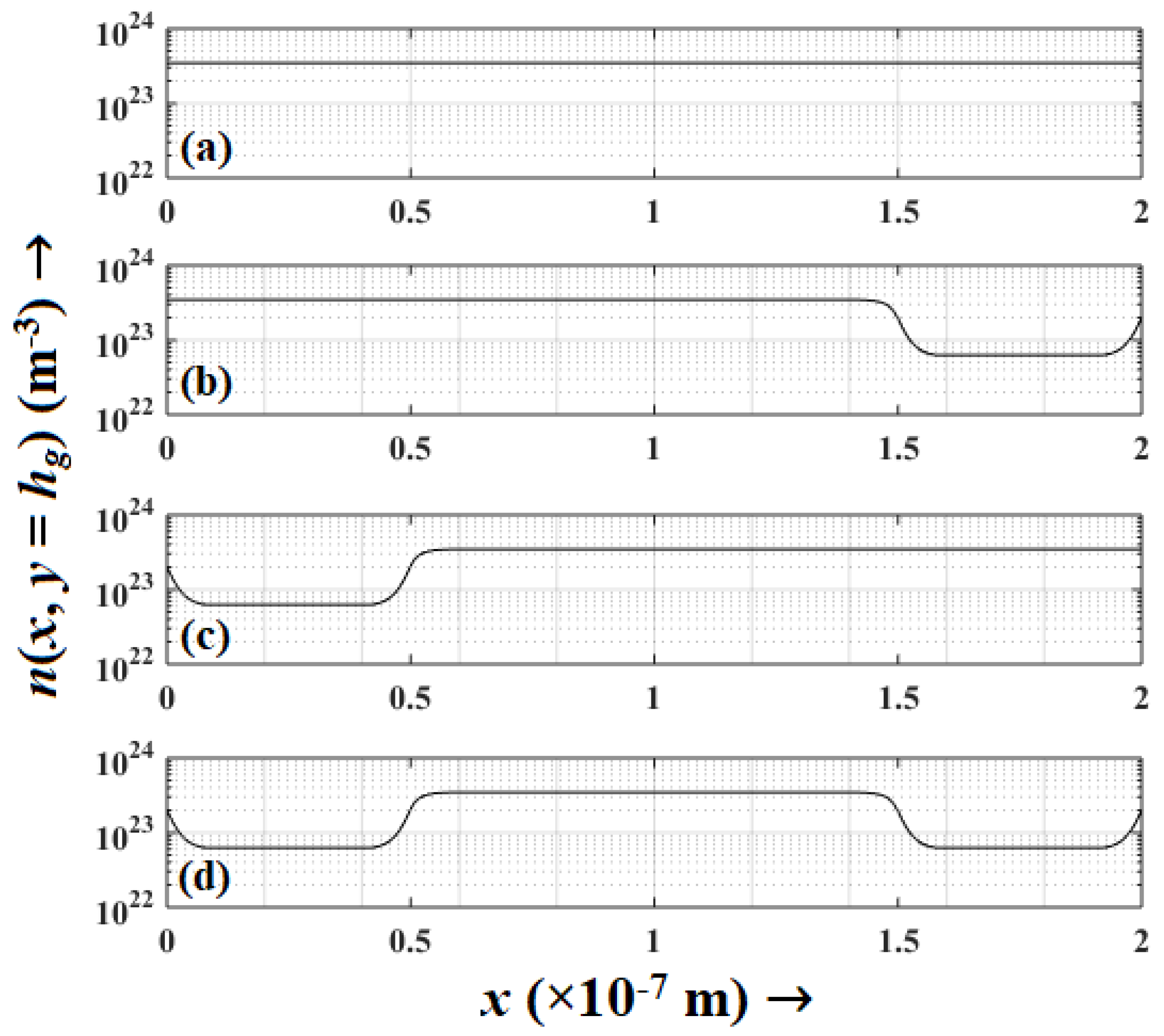
Initially, the flat and quasi-Read concentration profiles such as the hi-lo, lo-hi, lo-hi-lo profiles in the proposed HEM-ATT structures were confirmed by obtaining the partial electron distribution at the AlGaN/GaN interfaces (i.e., at y = hg for (LAu(Sch) + LNi(Sch)x ≤ (Ld + LAu(Sch) + LNi(Sch))) introduced by the polarization-induced sheet charges of the channel region. Figure 6a–d show the said distributions at the AlGaN/GaN interface along the 2-DEG channel region of HEM-ATT devices; clearly, the partial electron distributions exhibit the flat, hi-lo, lo-hi and lo-hi-lo density profiles in the corresponding HEM-ATT devices. Here, the partial electron density below the 20 nm thick AlGaN barrier layer was found to be 3.45 × 10²³ m−3, which corresponds to the high (hi) electron density region(s). Similarly, the partial electron density below the 10 nm thick trench regions was found to be 6.25 × 10²² m−3, which is associated with the low (lo) electron density regions. Therefore, by changing the thickness of the AlGaN barrier layer, the concentration profile of the channel region can be modified, and this property was utilized to realize the flat and quasi-Read density profile in the proposed structures.
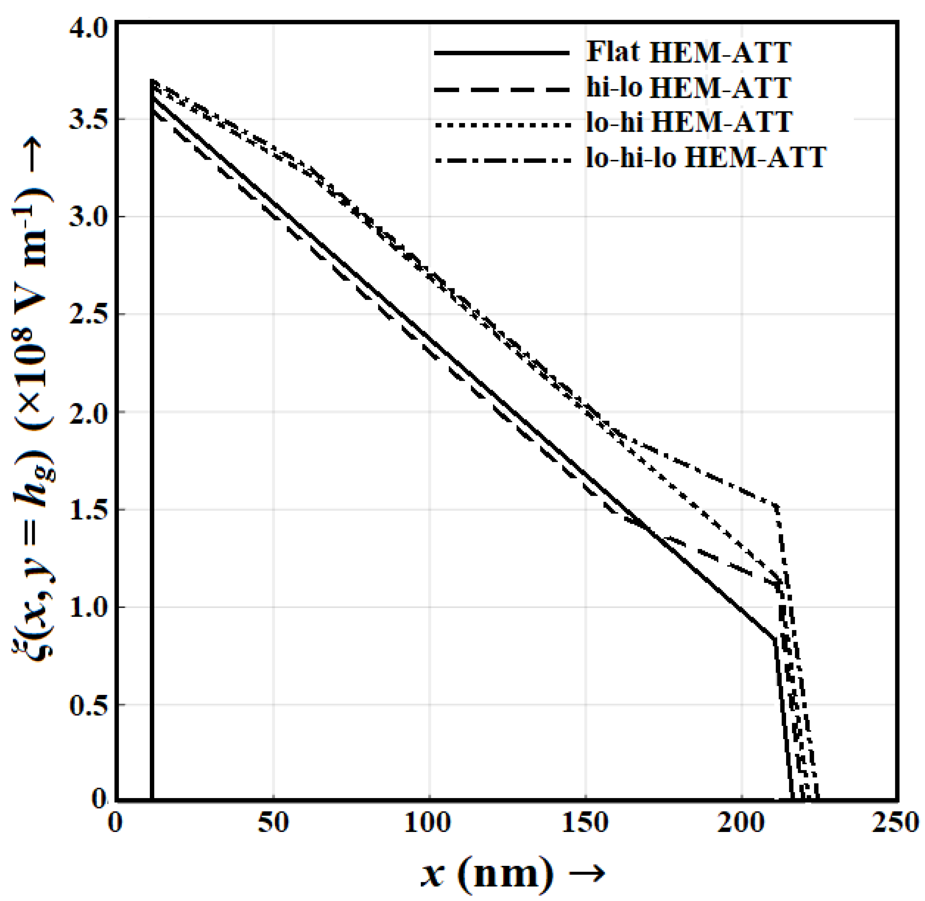
The electric field (ξ) profiles, that is, variations in electric field along the x-axis at the AlGaN/GaN interface, i.e., y = hg (ξ(x, y = hg) vs. x graphs) of the flat and quasi-read HEM-ATT diodes under reverse bias were obtained from the DC simulation. The electric field profiles of the device for the bias current density of 11.5 × 10⁸ A m−2 are shown in Figure 7. As per the Poisson equation, the electric field gradient ((x, y = hg)/dx) at any space point (x) in the 2-DEG is directly proportional to the electron concentration at that space point (n(x, y = hg)). It is evident from Figure 7 that the slope of the electric field profile in flat HEM-ATT throughout the channel is constant due to no variation in the electron concentration along the x-direction in 2-DEG (Figure 6a). However, the electric field profiles of quasi-Read HEM-ATT devices exhibit smaller slope within the regions having lower electron concentrations (i.e., lo-regions) and higher slope within the regions having higher electron concentrations (i.e., hi-regions); Figure 6b–d) exhibit the variations in electron concentrations in quasi-Read HEM-ATTs at the AlGaN/GaN interface. Additionally, the peak electric field value in HEM-ATT devices at the Schottky contact were found to be different due to the different electric field slopes and electron concentration variations throughout the channel region of the devices. The electric field punch-through effect at the cathode-side of the depletion layer was found to be more pronounced in quasi-Read HEM-ATTs as compared to a flat HEM-ATT due to the smaller average electric field slope in quasi-Read diodes along the channel region. Punch-through diodes have greater THz power delivery capability than the non-punch-through diodes, since the velocity saturation can be sustained throughout the channel region due to a non-zero high field at each space-points [77,78]. However, this effect slightly reduces DC to THz conversion efficiency [78].
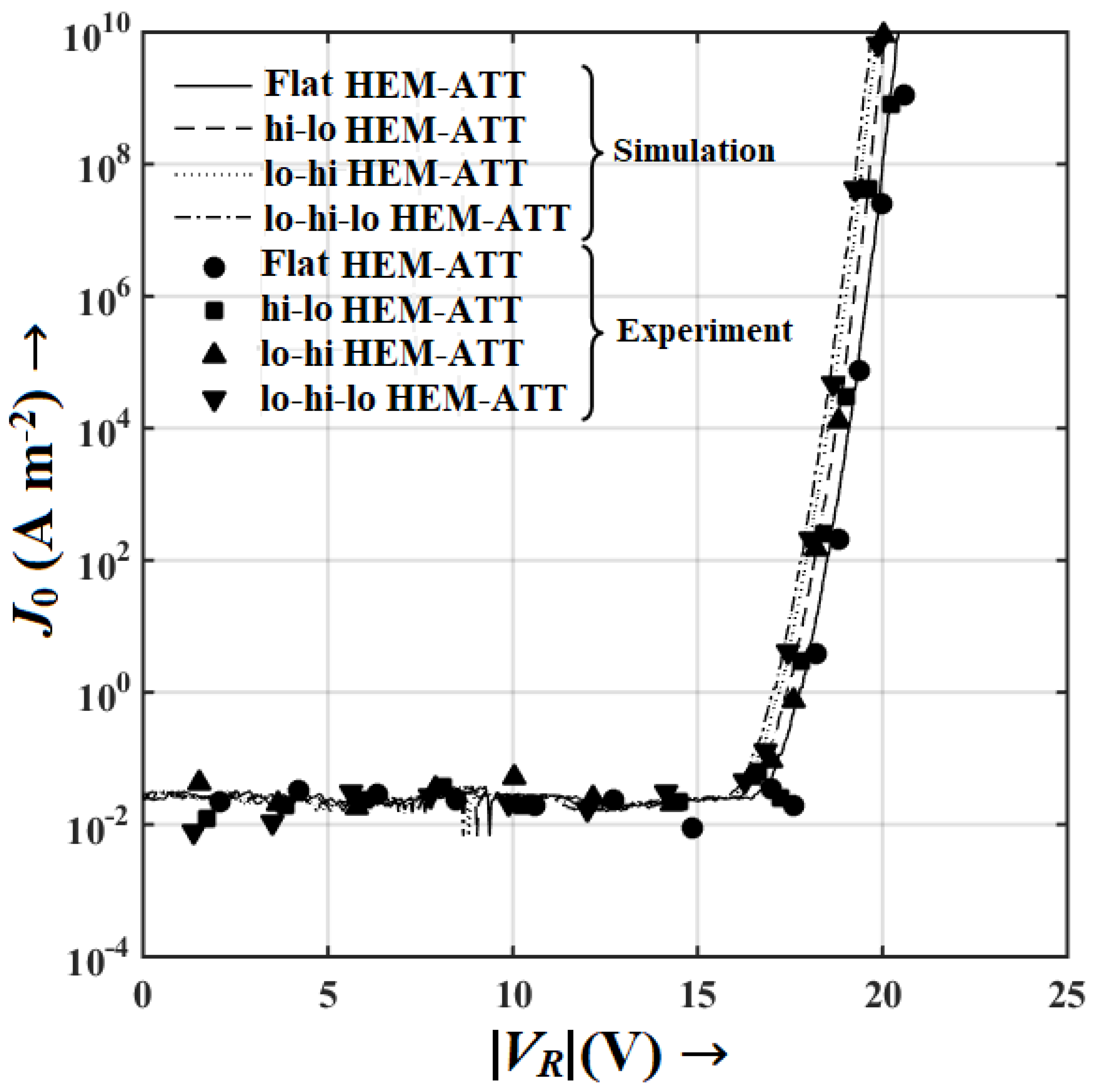
The Tektronix 4200A-SCS parameter analyzer and probe-station were used to carry out the current–voltage (I-V) characterization of HEM-ATT diode samples under reverse bias conditions. At first, two probes were connected to the SMU-1 (Source Measurement Unit—1) and GND (Ground) of the parameter analyzer. Then, SMU-1 and GND were loaded to the cathode and anode terminals of a diode sample, respectively. The Clarius software associated with the parameter analyzer was used to set up the voltage–current measurement steps. The magnitude of the reverse voltage (|VR|) was swept within the range of 0–24 V with a step size of 1.5 V and corresponding I0 values were measured and recorded. The current values were divided by the cross-sectional area in order to obtain the corresponding current density (J0) values. Finally, the experimentally measured J0 versus |VR| graphs for the flat, hi-lo, lo-hi and lo-hi-lo HEM-ATT diode samples were plotted and these graphs are shown in Figure 8. The I-V characteristics of the HEM-ATT diodes obtained from the DC simulation are also shown in Figure 8. It is noteworthy from Figure 8 that the I-V characteristics of the diodes obtained from the experimental measurements and DC simulation are in good agreement, which validates the simulation model adopted in the current work. All the HEM-ATT structures exhibit almost similar I-V characteristics. The breakdown voltages obtained from the DC simulation vary from 16.5 to 16.9 V. On the other hand, the experimentally measured breakdown voltages of the diodes varies from 17.0 to 18.1 V, which is in close agreement with the simulation results.
However, the breakdown voltage of a vertical SDR Schottky barrier quasi-Read diode (Figure 3) was found to be slightly smaller, i.e., 12.5 V, and the slope of the I-V curve after its breakdown was also observed to be smaller compared to that in the HEM-ATT diodes. On the other hand, due to the use of two drift regions (n- and p-GaN drift regions) in the DDR IMPATT diode (Figure 4), their breakdown voltage was found to be significantly higher, i.e., nearly 32 V. However, the slope of the breakdown curve after breakdown was observed to be much smaller as compared to that of the Schottky barrier HEM-ATT diodes. Therefore, the extraordinary properties of 2-DEG (primarily the improved mobility of 2-DEG electrons compared to bulky GaN electrons [64,65]) improve the breakdown characteristics of the HEM-ATT diodes, i.e., a significantly sharper breakdown can be achieved in HEM-ATT diodes compared to the SDR Schottky barrier quasi-Read diode and p-n junction-based DDR diode. The greater breakdown voltage of DDR IMPATT is a promising factor for obtaining a possible greater THz power output of the source. However, soft breakdown characteristics and greater parasitic series resistance as a result of the high-resistivity metal~p+-GaN ohmic contact result in a significant drop in the overall THz power output in the DDR IMPATT source, which will be discussed later.

6. Large-Signal Characteristics

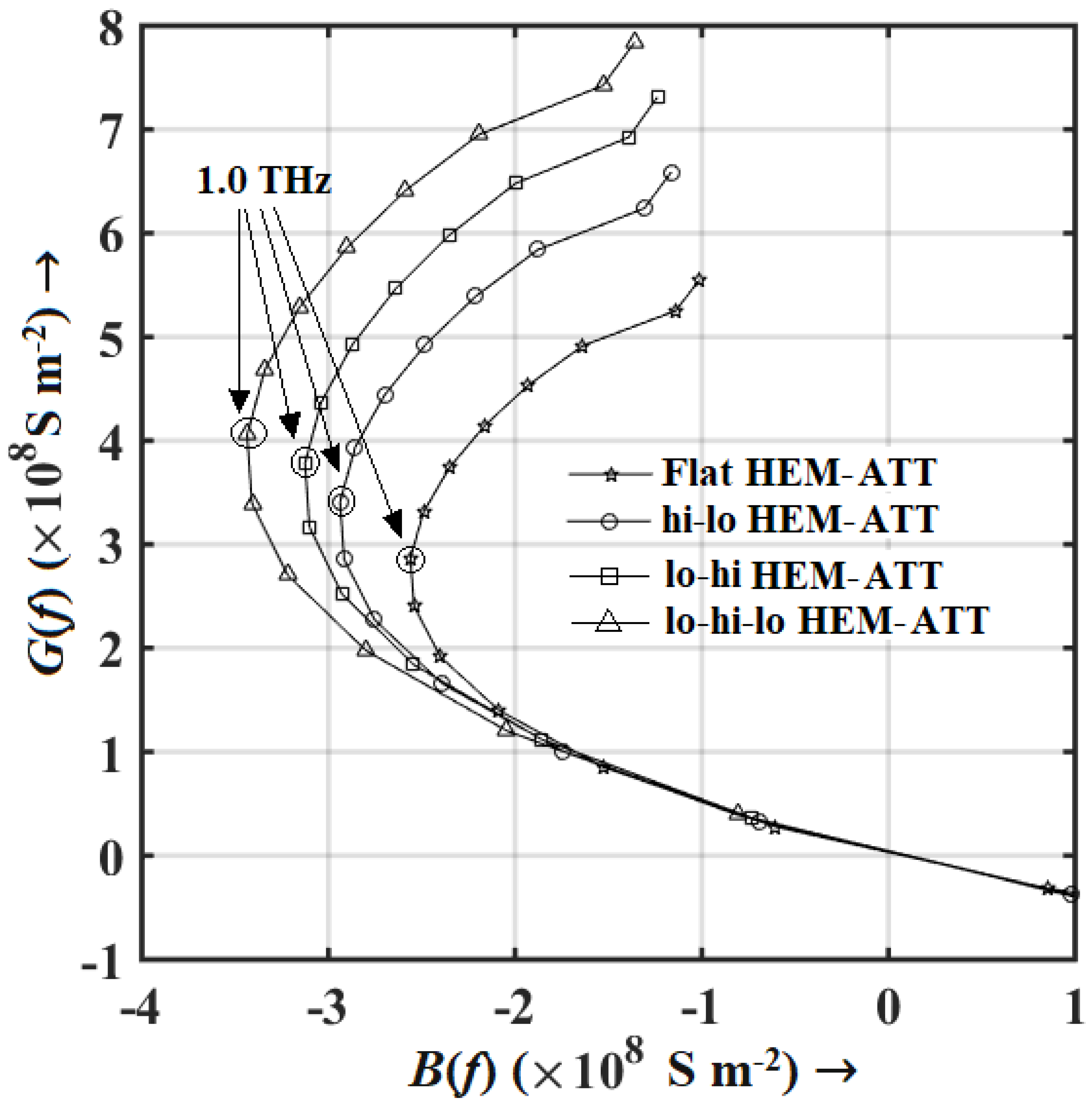
The large-signal simulation of HEM-ATT devices confirmed the region of oscillation and bandwidth. It was observed that the devices oscillate for the bias current density range of 6.0 × 10⁸–15.0 × 10⁸ A m−2, for which the operational frequency varies from 0.923 to 1.066 THz. Therefore, the oscillation bandwidth was found to be 143 GHz. An around 55% modulation index was achieved in a NSVE large-signal simulation for which the output THz power and conversion efficiency were maximum. The output parameters of the steady-state DC simulation, such as bias current density, breakdown voltage, avalanche region voltage drop, avalanche region width, etc., were used as the initial conditions for the time-dependent NSVE large-signal simulation of HEM-ATT sources. Large-signal time-domain terminal current and voltage waveforms (id(t) and vd(t)) were Fourier transformed (by using a suitable fast Fourier transform (FFT) algorithm) to obtain the frequency domain response of those (Id(f) and Vd(f)). The knowledge of the frequency domain response of the diode current and voltage provides the diode admittance (Yd(f) = Id(f)/Vd(f)) as a function of frequency. The real and imaginary parts of the diode admittance (Yd(f) = G(f) + j B(f)), i.e., conductance(G(f)) and susceptance (B(f) can easily be resolved in order to obtain the conductance–susceptance (G-B) plots or admittance characteristics of the diode for different bias current densities. The admittance characteristics of a HEM-ATT diode for the bias current density of 11.5 × 10⁸ A m−2 obtained from the large-signal simulation are shown in Figure 9. In these G-B curves, the effect of parasitic series resistance is not included. It is observed that the lo-hi-lo HEM-ATT exhibits the largest peak magnitude of negative conductance (−3.436 × 10⁸ S m−2), whereas the flat HEM-ATT exhibits the smallest, i.e., −2.56 × 10⁸ S m−2 at 1.0 THz. The magnitude of peak negative conductance at 1.0 THz in hi-lo and lo-hi HEM-ATT are −2.938 × 10⁸ and −3.126 × 10⁸ S m−2, respectively, which are considerably higher than that of the flat HEM-ATT diode. A narrower avalanche zone width in quasi-Read diodes is the primary reason behind their higher magnitude of negative conductance.
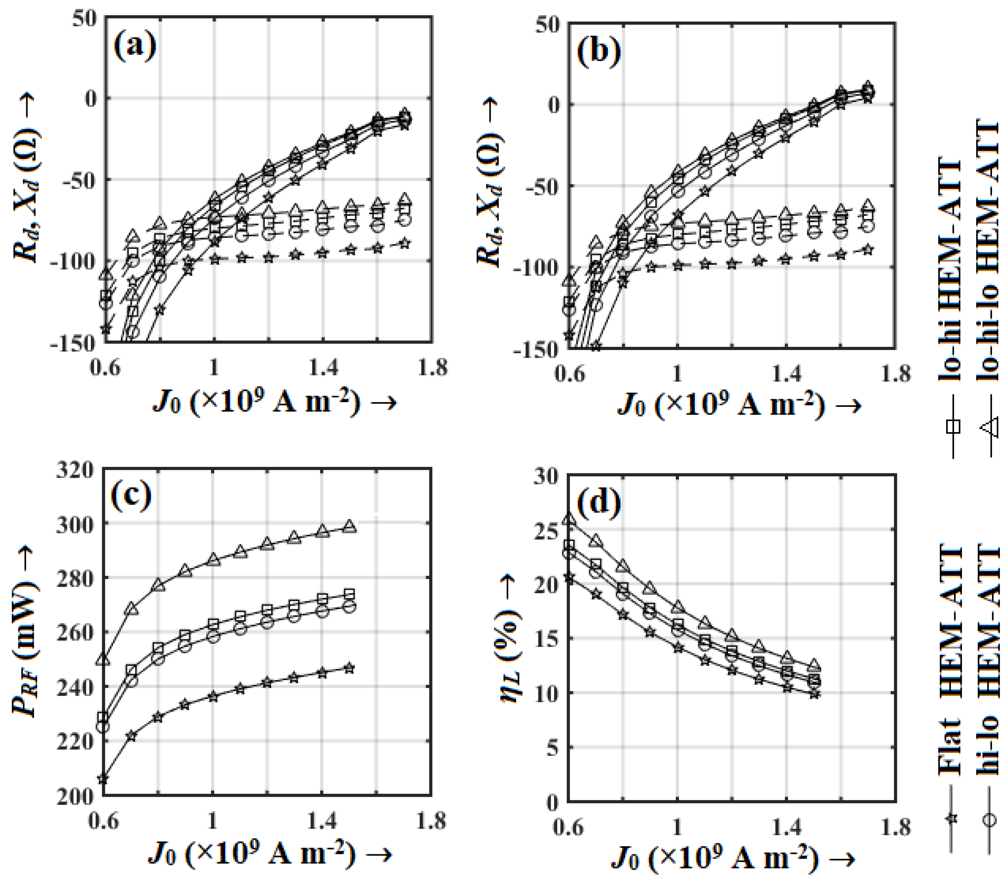
The series resistances of the diodes was calculated by using a large-signal technique based on depletion width modulation under large-signal operating conditions [71]. The influence of the skin effect at THz frequencies was also taken into consideration while estimating the series resistance (Rs) value [72]. The variation in diode resistance (Rd(f) = G(f)/(G2(f) + B2(f)) and reactance (Xd(f) = −B(f)/(G2(f) + B2(f)) with bias current density without considering the effect of series resistance and with considering it are shown in Figure 10a,b, respectively. The magnitude of series resistance was estimated to be in the range of 18–20 Ω in HEM-ATT diodes. The magnitude of negative resistance of the diode decreases due to the positive series resistance and changes the sign of the diode resistance (Rd(f)) from negative to positive beyond the bias current density of 15.0 × 10⁸ A m−2, which results in diodes being non-oscillating beyond that bias current density. If the value of the series resistance increases, then the upper bound of the operating bias current density range (here it is 6.0 × 10⁸–15.0 × 10⁸ A m−2) is further reduced, which results in a narrowing down of the oscillation bandwidth. The highest magnitude of the negative diode resistance without considering the series resistance varies between 110 and 150 Ω in the THz regime. Therefore, if the series resistance increases beyond 100 Ω, the power out is significantly smaller (since the sign of the overall diode resistance (Rd(f) + Rs) is negative but its magnitude is very low), and if the value of Rs increases beyond 150 Ω, then the diode does not oscillate (since the sign of the overall diode resistance (Rd(f) + Rs) becomes positive). The variation in peak power output (PRF) and DC to THz conversion efficiency of HEM-ATT diodes bias current density obtained from the large-signal simulation are shown in Figure 10c,d, respectively. The highest power output of nearly 300 mW is achievable in a lo-hi-lo HEM-ATT source with 11% conversion efficiency at 1.066 THz. The breakdown voltage (VB) and the magnitude of the peak negative conductance (|Gp|) of the ATT device increase with the increase in the bias current density (J0) [23,24]. However, the rates of increase in both VB and |Gp| with respect to J0, i.e., dVB/dJ0 and d|Gp|/dJ0 are considerably small compared to the rate of increase in DC power input (PDC = I0VB; where I0 = J0 × cross-sectional with the increase in bias current density (i.e., dPDC/dJ0 >> dVB/dJ0, d|Gp|/dJ0). Although the PRF, i.e., the numerator of Equation (3) increases due to the increase in both VB and |Gp|, the denominator of Equation (3) increases at a considerably larger rate with the increase in the bias current density. Consequently, the conversion efficiency (ηL) deteriorates with the increase in bias current density.
The comparison of THz power delivery capability and conversion efficiency between the lateral HEM-ATT source and vertical SDR Schottky barrier and GaN DDR IMPATT source is illustrated in Figure 11. It is clearly observable that the HEM-ATT is capable of delivering significantly higher THz power (250–300 mW) compared to the vertical SDR Schottky (56 mW) and GaN DDR (10 µW) sources. The primary cause of the significantly low THz power output of the GaN DDR IMPATT source (almost four orders smaller) is the high value of parasitic series resistance of the GaN DDR IMPATT diode. The minimum experimentally obtained resistivity of the metal~p+-GaN contact is around 1.0 Ω cm [25,26], which is about 3–4 orders larger than the metal~n+-GaN contact resistivity [79]. The compulsory metal~p+-GaN contact in p+-p-n-n+ structured DDR IMPATT rises the value of series resistance beyond 120 Ω under the large-signal operating condition in the THz regime and finally leads to very small (~few tens of µW) THz power output with considerably small conversion efficiency (nL << 1.0%). Therefore, the Schottky barrier SDR structures must be always preferred over the GaN DDR structure for realizing THz sources in order to avoid the highly resistive metal~p+-GaN contact. Moreover, the excellent properties of 2-DEG lead the HEM-ATT source to deliver almost one order higher THz power output compared to the vertical Schottky barrier SDR IMPATT source. Therefore, the proposed lateral quasi-Read Schottky barrier HEM-ATT structures excel over all other possible GaN based ATT structures with regard to THz performance. The hi-lo, lo-hi and lo-hi-lo quasi-Read density profiles of the channel regions of the Schottky barrier HEM-ATT diodes result in a narrowing down of the avalanche region width due to sharper avalanche growth [66] compared to the flat-profile Schottky barrier HEM-ATT and p-n junction-based DDR diodes. The sharper avalanche growth in quasi-Read Schottky barrier HEM-ATT diodes leads to greater DC to THz conversion efficiency and greater power output.

7. Noise Performance

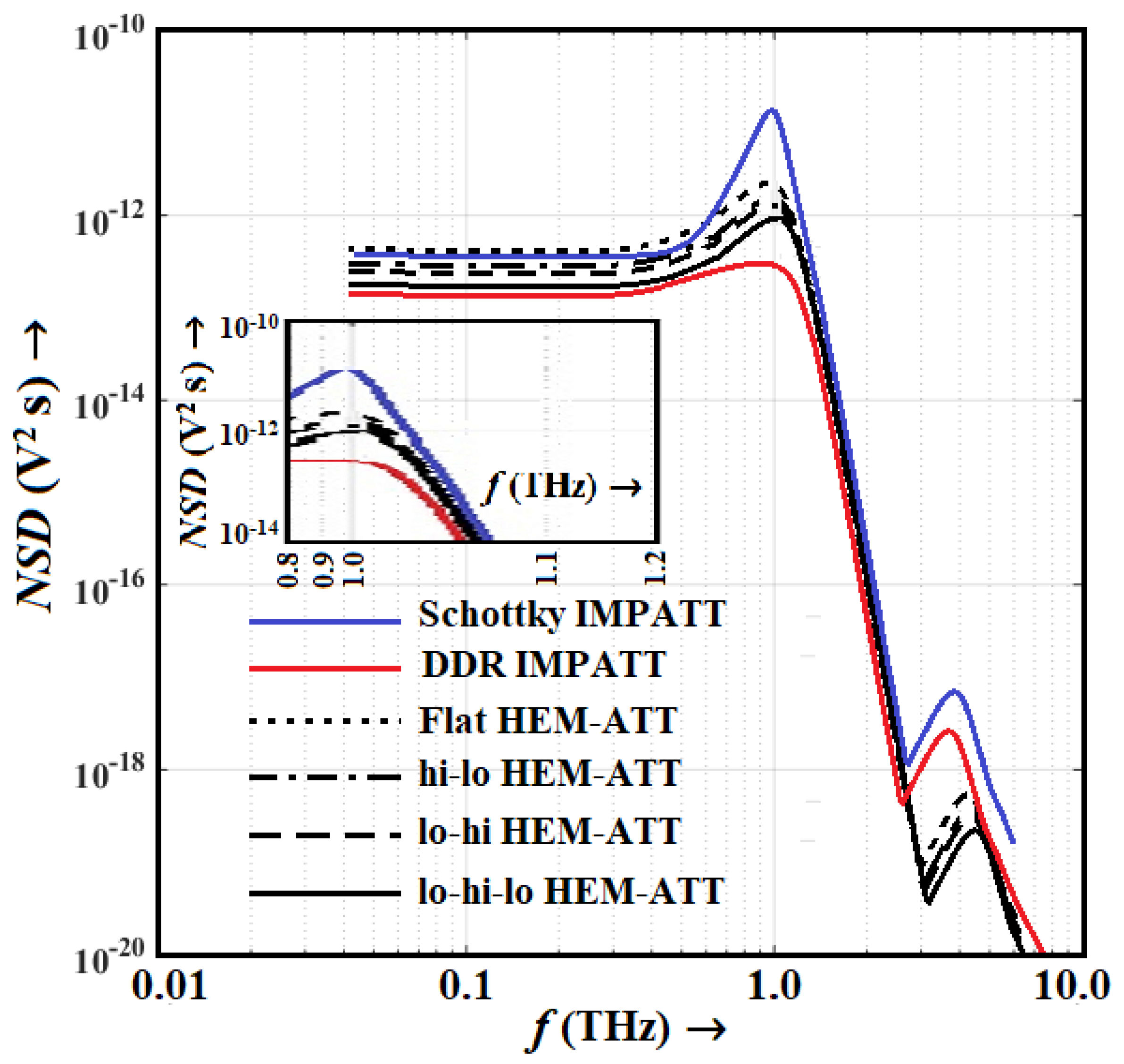
The avalanche noise performance of the lateral HEM-ATT source was analyzed using the DIFM small-signal noise simulation method [73,74]. The noise simulation of vertical Schottky barrier SDR and GaN DDR IMPATT sources was also carried out in order to compare their noise performance with the noise performance of lateral Schottky barrier HEM-ATT sources in the THz regime. The NSD versus frequency plots shown in Figure 12 show that peak NSD can be significantly suppressed by using the quasi-Read HEM-ATT structures compared to the conventional vertical Schottky barrier SDR structure. The HEM-ATT structures utilizes an intentionally undoped channel region, where the electrons remain confined within the quantized energy levels formed inside the triangular potential barrier situated just below the AlGaN/GaN interface; those electrons constitute the 2-DEG. The current-carrying electrons moving through the channel of HEM-ATT exhibit significantly improved mobility due to the reduced ionized impurity scattering mechanism in the 2-DEG compared to the impurity-scattering-limited mobility of electrons in the Schottky barrier SDR device. Moreover, the reduced impurity scattering probability in 2-DEG suppresses the probability of random fluctuations in noise field due to the very small amount of interaction of charge carriers with the ionized impurities within the active region of the HEM-ATT. As a result, the NSD peak in HEM-ATTs is considerably reduced compared to that in a Schottky barrier SDR device. The hi-lo, lo-hi and lo-hi-lo quasi-Read 2-DEG electron density profiles of HEM-ATT diodes result in a narrowing down of the avalanche region width due to the sharp avalanche growth within the avalanche region. As a result of the smaller avalanche region width in these quasi-Read HEM-ATT diodes, the random fluctuations in noise field are restricted to a narrower region compared to the flat 2-DEG electron density profile HEM-ATT diode. As a result, the overall noise performance of the quasi-Read HEM-ATT sources was found to be better than the flat HEM-ATT source. This improvement in noise performance was observed to be at its maximum in lo-hi-lo HEM-ATT due to the narrowest avalanche region width among all the HEM-ATT structures under consideration.
However, the NSD of a conventional GaN DDR IMPATT source is significantly smaller compared to the Schottky-barrier-diode-based sources. The noise measure versus frequency plots shown in Figure 13 also exhibit a similar trend. The noise measure of HEM-ATT sources varies from 11.92 to 13.85 dB at 1.0 THz, whereas the same is observed to be 16.09 dB at 1.0 THz in the vertical Schottky SDR source. However, the GaN DDR IMPATT source was proven to be the least noisy THz source, with a noise measure of 10.2 dB at 1.0 THz. That being said, while the noise performance of the vertical GaN DDR IMPATT source was found to be better than the Schottky barrier HEM-ATT based THz sources, its THz power output is significantly smaller (~10 μW). Thus, the vertical GaN DDR IMPATT diode is not a good recommendation for realizing THz sources. On the other hand, the high-power HEM-ATT sources with compatible noise performance are the most suitable candidates for experimentally realizing high-power, high-efficiency THz sources.

8. Comparison with Other THz Sources

A comparative study is presented in this section between different commercially available state-of-the-art THz oscillators operating nearly at 1.0 THz and 1.0 THz Schottky barrier HEM-ATT sources based on AlGaN/GaN 2-DEG. Some important specifications, frequency range of operation, peak THz power output and DC to THz conversion efficiency of the state-of-the-art THz sources such as carcinotrons, folded waveguide sources, backward wave oscillators (BWOs), quantum cascade lasers (QCLs), high-electron-mobility transistors (HEMTs), planner Schottky barrier diode multipliers and harmonic oscillator arrays are listed in Table 2 [80,81,82,83,84,85,86,87,88,89,90]. The most promising source for THz generation in the frequency range of 0.85–1.03 THz is observed to be the BWO with narrow corrugated waveguide slow wave structure fabricated and tested by Mineo et al. in the year 2012 [82]. They obtained 200 mW of RF power output within the tuning range of 0.85–1.03 THz. Other devices shown in Table 1 are capable of delivering very low THz power (few µW–mW) with considerably low conversion efficiency (<1.0%) at THz frequencies. In comparison, the Schottky barrier lo-hi-lo HEM-ATT source is capable of delivering comparatively higher THz power (250–300 mW) with appreciable higher DC to THz conversion efficiency (11–25%) within the frequency range of 0.923–1.066 THz (oscillation bandwidth is 0.143 THz). Moreover, very low voltage (16.5 to 16.9 V) is required to achieve the breakdown of Schottky barrier HEM-ATT diodes at the operational condition, while a minimum cathode voltage in the order of kilovolts (KV) is required to achieve the operational condition of THz BWOs. Thus, the proposed Schottky barrier HEM-ATT sources have immense potentiality to be established as more promising and reliable THz sources compared to the existing THz sources [80,81,82,83,84,85,86,87,88,89,90].

9. Background Prospective of Biomedical Application

Due to the recent rapid advancement in microfabrication and materials engineering, the possibility for Terahertz biomedical spectroscopy is approaching mainstream medical imaging techniques. THz is exciting due to the non-ionizing nature of the radiation yet simultaneous capability of high-resolution soft-tissue and cellular imaging for diagnostic application. Our previous reviews report on the prospect of the medical application of Terahertz waves with a comprehensive understanding of various imaging parameters (sample preparation, effect of water reflection in live tissue, signal-to-noise ratio, image resolution, image contrast, etc.) correlated with the highlighted and relevant clinical results [91,92,93,94,95]. Furthermore, we have experimentally reported on and extensively studied the development of on-chip Terahertz microbolometer detectors [96,97,98,99], and conceived the design concept for the chip integrable medical device and image processing for possible use in cancer cell screening [100]. These on-chip Terahertz microbolometers demonstrated peak responsivity ~1 THz with improved noise-equivalent power (NEP) and response speed at room temperature [97,98]; however, they may not be adequate for thermal imaging with acceptable integration times. However, the device arrays can be still employed in imaging systems that utilize an active THz source. Here, the possibility of a chip-integrable solid-state THz source is reported. The proposed AlGaN/GaN based Schottky barrier lateral HEM-ATT can deliver a notable ~300 mW, operating at 1.0 THz frequency, with significantly improved noise performance, suitable for compact biomedical spectroscopy systems as a solid-state source.

10. Conclusions

Schottky barrier lateral HEM-ATT structures based on AlGaN/GaN 2-DEG are proposed for generating a 1.0 THz frequency. One and more than one trenches were introduced at different positions of the top AlGaN barrier layer in order to realize different quasi-Read electron density profiles in the 2-DEG channel region such as hi-lo, lo-hi and lo-hi-lo. The static or DC simulation of HEM-ATTs was carried out in the Silvaco ATLAS device simulation platform, whereas the THz and noise performances of the device were investigated by using natively developed NSVE large-signal model and DEFM small-signal model-based simulation techniques, respectively. The breakdown voltages of the devices estimated via simulation were validated by using experimental measurements and those were found to be around 17–18 V. A maximum series resistance of around 20 Ω was found to be present in the device under large-signal operating conditions. The large-signal simulation shows that the Schottky barrier lo-hi-lo HEM-ATT source is capable of delivering 250–300 mW of THz power with an appreciably high DC to THz conversion efficiency ranging from 11 to 25% within the frequency range of 0.923–1.066 THz, i.e., the bandwidth of oscillation is nearly 0.143 THz; this is a significant improvement compared to the achievable THz power output and efficiency from the conventional THz DDR IMPATT source. The noise performance of the THz source was found to be significantly improved by using the quasi-Read HEM-ATT structures compared to the conventional vertically oriented Schottky barrier IMPATT structure. By the lateral integration of multiple HEM-ATT diodes, an oscillator array can be realized on the monolithic integrated circuit in order to implement broadband THz sources. Moreover, a third terminal (gate) can be realized over the AlGaN layer for directly modulating power and frequency via an externally applied signal. In the proposed HEM-ATT structures, optical signal coupling and injection locking were also very much convenient through the thin AlGaN barrier layer. The proposed HEM-ATT source is compatible with the state-of-the-art semiconductor fabrication technologies with the potential for application as on-chip integrable THz solid-state sources in compact biomedical spectroscopy systems.

Author Contributions

Methodology, S.K., A.A., H.I., H.S., A.B. (Arindam Biswas), R.S.D., A.B. (Amit Banerjee) and A.Y.S.; Formal analysis, S.K., A.A., H.I., H.S., A.B. (Arindam Biswas), R.S.D., A.B. (Amit Banerjee) and A.Y.S.; Investigation, S.K., A.A., H.I., H.S., A.B. (Arindam Biswas), R.S.D., A.B. (Amit Banerjee) and A.Y.S.; Writing—original draft preparation, S.K., A.A., H.I., H.S., A.B. (Arindam Biswas), R.S.D., A.B. (Amit Banerjee) and A.Y.S.; Writing—review and editing, S.K., A.A., H.I., H.S., A.B. (Arindam Biswas), R.S.D., A.B. (Amit Banerjee) and A.Y.S. All authors have read and agreed to the published version of the manuscript.

Funding

This research was supported by the Japan–India Science Cooperative Program between JSPS and DST, Grant number [JPJSBP120207708 (Japan), DST/INT/JNPS/P-310/2020 (India)] and the 2023 cooperative research project on Biomedical Engineering (Project No. 2055), funded by the Research Centre for Biomedical Engineering, Japan in association with RIE, Shizouka University, Japan. This research is partially supported by the Device Development Programme (DST/TDT/DDP-38/2021), by the Department of Science Technology, Ministry of Science and Technology, Government of India.

Acknowledgments

The authors are grateful to Hiroshi Amano, Manabu Arai and Seiya Kawasaki of Nagoya University for fruitful discussions.

Conflicts of Interest

The authors declare no conflict of interest.

References

  1. Siegel, P.H. THz Instruments for Space. IEEE Trans. Antennas Propag. 2007, 55, 2957–2965. [Google Scholar] [CrossRef]
  2. Grischkowsky, D.; Keiding, S.R.; Van Exter, M.; Fattinger, C. Far-infrared time-domain spectroscopy with terahertz beams of dielectrics and semiconductors. J. Opt. Soc. Am. B 1990, 7, 2006–2015. [Google Scholar] [CrossRef]
  3. Debus, C.; Bolivar, P.H. Frequency selective surfaces for high sensitivity terahertz sensing. Appl. Phys. Lett. 2007, 91, 184102. [Google Scholar] [CrossRef]
  4. Yasui, T.; Yasuda, T.; Sawanaka, K.-I.; Araki, T. Terahertz paintmeter for noncontact monitoring of thickness and drying progress in paint film. Appl. Opt. 2005, 44, 6849–6856. [Google Scholar] [CrossRef] [Green Version]
  5. Stoik, C.D.; Bohn, M.J.; Blackshire, J.L. Nondestructive evaluation of aircraft composites using transmissive terahertz time domain spectroscopy. Opt. Express 2008, 16, 17039–17051. [Google Scholar] [CrossRef]
  6. Jördens, C.; Koch, M. Detection of foreign bodies in chocolate with pulsed terahertz spectroscopy. Opt. Eng. 2008, 47, 037003. [Google Scholar] [CrossRef]
  7. Fitzgerald, A.J.; Cole, B.E.; Taday, P.F. Nondestructive Analysis of Tablet Coating Thicknesses Using Terahertz Pulsed Imaging. J. Pharm. Sci. 2005, 94, 177–183. [Google Scholar] [CrossRef]
  8. Siegel, P. Terahertz Technology in Biology and Medicine. IEEE Trans. Microw. Theory Tech. 2004, 52, 2438–2447. [Google Scholar] [CrossRef]
  9. Ward, J.; Schlecht, E.; Chattopadhyay, G.; Maestrini, A.; Gill, J.; Maiwald, F.; Javadi, H.; Mehdi, I. Capability of THz Sources based on Schotiky diode frequency multiplier chains. In Proceedings of the 2004 IEEE MTT-S International Microwave Symposium Digest (IEEE Cat. No.04CH37535), Fort Worth, TX, USA, 6–11 June 2004; pp. 1587–1590. [Google Scholar]
  10. Heyminck, S.; Güsten, R.; Graf, U.; Stutzki, J.; Hartogh, P.; Hübers, H.W.; Ricken, O.; Klein, B. GREAT: Ready for early science aboard SOFIA. In Proceedings of the 20th International Symposium on Space Terahertz Technology, Charlottesville, VA, USA, 20–22 April 2009; pp. 315–317. [Google Scholar]
  11. Crowe, T.W.; Hesler, J.L.; Retzloff, S.A.; Pouzou, C.; Schoenthal, G.S. Solid State LO Sources for Greater than 2 THz. In Proceedings of the 22nd International Symposium on Space Terahertz Technology, Tucson, AZ, USA, 25–28 April 2011. [Google Scholar]
  12. Crowe, T.W.; Hesler, J.L.; Retzloff, S.A.; Pouzou, C.; Hester, J.L. Multiplier based sources for frequencies above 2 THz. In Proceedings of the 36th International Conference on Infrared, Millimeter and Terahertz Sources (IRMMW-THz), Houston, TX, USA, 2–7 October 2011; pp. 1–4. [Google Scholar]
  13. Maestrini, A.; Mehdi, I.; Siles, J.V.; Ward, J.; Lin, R.; Thomas, B.; Lee, C.; Gill, J.; Chattopadhyay, G.; Schlecht, E.; et al. First Demonstration of a Tunable Electronic Source in the 2.5 to 2.7 THz Range. IEEE Trans. Terahertz Sci. Technol. 2012, 3, 1–10. [Google Scholar]
  14. Williams, B.S. Terahertz quantum-cascade lasers. Nat. Photonics 2007, 1, 617–626. [Google Scholar] [CrossRef] [Green Version]
  15. Lai, R.; Mei, X.B.; Deal, W.R.; Yoshida, W.; Kim, Y.M.; Liu, P.H.; Lee, J.; Uyeda, J.; Radisic, V.; Lange, M.; et al. Sub 50 nm InP HEMT device with Fmax greater than 1 THz. In Proceedings of the 2007 IEEE International Electron Devices Meeting, Washington, DC, USA, 10–12 December 2007; pp. 609–611. [Google Scholar]
  16. Deal, W.R.; Mei, X.B.; Radisic, V.; Leong, K.; Sarkozy, S.; Gorospe, B.; Lee, J.; Liu, P.H.; Yoshida, W.; Zhou, J.; et al. Demonstration of a 0.48 THz Amplifier Module Using InP HEMT Transistors. IEEE Microw. Wirel. Compon. Lett. 2010, 20, 289–291. [Google Scholar] [CrossRef]
  17. Urteaga, M.; Seo, M.; Hacker, J.; Griffith, Z.; Young, A.; Pierson, R.; Rowell, P.; Skalare, A.; Rodwell, M. InP HBT integrated circuit technology for terahertz frequencies. In Proceedings of the 2010 IEEE Compound Semiconductor Integrated Circuit Symposium (CSICS), Monterey, CA, USA, 3–6 October 2010; pp. 1–4. [Google Scholar]
  18. Lobisser, E.; Griffith, Z.; Jain, V.; Thibeault, B.; Rodwell, M.; Loubychev, D.; Snyder, A.; Wu, Y.; Fastenau, J.; Liu, A. 200-nm InGaAs/InP type-I DHBT employing a dual-sidewall emitter process demonstrating fmax >> 800 GHz and fT = 360 GHz. In Proceedings of the 2009 IEEE International Conference on Indium Phosphide & Related Materials, Newport Beach, CA, USA, 10–14 May 2009; pp. 16–19. [Google Scholar]
  19. Seo, M.; Urteaga, M.; Young, A.; Jain, V.; Griffith, Z.; Hacker, J.; Rowell, P.; Pierson, R.; Rodwell, M. >300 GHz fixed-frequency and voltage-controlled fundamental oscillators in an InP HBT process. In Proceedings of the 2010 IEEE MTT-S International Microwave Symposium, Anaheim, CA, USA, 23–28 May 2010; pp. 272–275. [Google Scholar]
  20. Hacker, J.; Seo, M.; Young, A.; Griffith, Z.; Urteaga, M.; Reed, T.; Rodwell, M. THz MMICs based on InP HBT technology. In Proceedings of the IEEE MTT-S International Microwave Symposium Digest, Anaheim, CA, USA, 23–28 May 2010; pp. 1126–1129. [Google Scholar]
  21. Seo, M.; Urteaga, M.; Hacker, J.; Young, A.; Griffith, Z.; Jain, V.; Pierson, R.; Rowell, P.; Skalare, A.; Peralta, A.; et al. In P HBT IC technology for terahertz frequencies: Fundumental oscillators up to 0.57 THz. IEEE J. Solid-State Circuits 2011, 46, 2203–2214. [Google Scholar] [CrossRef]
  22. Li, X.; Yang, L.A.; Ma, X.; Hao, Y. A new lattice-matched In0.17Al0.83N~ GaN based heterostructure IMPATT diode for terahertz application. Semicond. Sci. Technol. 2019, 34, 115011. [Google Scholar] [CrossRef]
  23. Acharyya, A.; Banerjee, J. Potentiality of IMPATT Devices as Terahertz Source: An Avalanche Response Time-based Approach to Determine the Upper Cut-off Frequency Limits. IETE J. Res. 2013, 59, 118. [Google Scholar] [CrossRef]
  24. Acharyya, A.; Banerjee, J.P. Prospects of IMPATT devices based on wide bandgap semiconductors as potential terahertz sources. Appl. Nanosci. 2012, 4, 1–14. [Google Scholar] [CrossRef] [Green Version]
  25. Horita, M.; Takashima, S.; Tanaka, R.; Matsuyama, H.; Ueno, K.; Edo, M.; Takahashi, T.; Shimizu, M.; Suda, J. Hall-effect measurements of metalorganic vapor-phase epitaxy-grown p-type homoepitaxial GaN layers with various Mg concentrations. Jpn. J. Appl. Phys. 2017, 56, 031001. [Google Scholar] [CrossRef]
  26. Liu, Y. Recent research on ohmic contacts on GaN-based materials. IOP Conf. Ser. Mater. Sci. Eng. 2020, 738, 012007. [Google Scholar] [CrossRef]
  27. Acharyya, A.; Biswas, A.; Kar, S.; Satoh, H.; Inokawa, H. Possibilities of Realizing an Integrated Power Module for Terahertz Wave Generation. In New Horizons in Millimeter-Wave, Infrared and Terahertz Technologies; Lecture Notes in Electrical Engineering; Springer: Singapore, 2022; Volume 953, pp. 21–40. [Google Scholar] [CrossRef]
  28. Banerjee, P.; Acharyya, A.; Biswas, A.; Inokawa, H.; Bhattacharjee, A.K. Edge Terminated GaN Reverse Double-Drift IMPATT Structure for Millimeter-Wave Generation. IETE J. Res. 2022. submitted. [Google Scholar]
  29. Zhang, X.-Y.; Yang, L.-A.; Yang, W.-L.; Li, Y.; Ma, X.-H.; Hao, Y. Improved performance of Ni/GaN Schottky barrier impact ionization avalanche transit time diode with n-type GaN deep level defects. Semicond. Sci. Technol. 2020, 36, 025001. [Google Scholar] [CrossRef]
  30. Zhang, X.-Y.; Yang, L.-A.; Ma, Y.; Liu, Y.-C.; Yang, W.-L.; Ma, X.-H.; Hao, Y. Noise characteristics of Ni/GaN Schottky barrier IMPATT diode based on polar- and nonpolar-oriented wurtzite GaN for terahertz application. Superlattices Microstruct. 2020, 139, 106405. [Google Scholar] [CrossRef]
  31. Li, X.; Yang, L.A.; Zhang, X.; Ma, X.; Hao, Y. GaN/Alx Ga1−x N/GaN heterostructure IMPATT diode for D-band applications. Appl. Phys. A Solids Surf. 2019, 125, 205–215. [Google Scholar] [CrossRef]
  32. Farahmand, M.; Garetto, C.; Bellotti, E.; Brennan, K.; Goano, M.; Ghillino, E.; Ghione, G.; Albrecht, J.; Ruden, P. Monte Carlo simulation of electron transport in the III-nitride wurtzite phase materials system: Binaries and ternaries. IEEE Trans. Electron Devices 2001, 48, 535–542. [Google Scholar] [CrossRef] [Green Version]
  33. Yu, T.-H.; Brennan, K.F. Monte Carlo calculation of two-dimensional electron dynamics in GaN–AlGaN heterostructures. J. Appl. Phys. 2002, 91, 3730–3736. [Google Scholar] [CrossRef]
  34. Zhang, X.-Y.; Yang, L.-A.; Hu, X.-L.; Yang, W.-L.; Liu, Y.-C.; Li, Y.; Ma, X.-H.; Hao, Y. Simulation Study of Lateral Schottky Barrier IMPATT Diode Based on AlGaN/GaN 2-DEG for Terahertz Applications. IEEE Trans. Electron Devices 2022, 69, 1006–1013. [Google Scholar] [CrossRef]
  35. Martyniuk, P.; Antoszewski, J.; Faraone, L.; Rogalski, A. New concepts in infrared photodetector designs. Appl. Phys. Rev. 2014, 1, 041102. [Google Scholar] [CrossRef] [Green Version]
  36. Woodward, R.M.; E Cole, B.; Wallace, V.P.; Pye, R.J.; Arnone, D.D.; Linfield, E.H.; Pepper, M. Terahertz pulse imaging in reflection geometry of human skin cancer and skin tissue. Phys. Med. Biol. 2002, 47, 3853–3863. [Google Scholar] [CrossRef]
  37. Nagel, M.; Bolivar, P.H.; Brucherseifer, M.; Kurz, H.; Bosserhoff, A.; Büttner, R. Integrated THz technology for label-free genetic diagnostics. Appl. Phys. Lett. 2002, 80, 154–156. [Google Scholar] [CrossRef]
  38. Karpowicz, N.; Zhong, H.; Zhang, C.; Lin, K.-I.; Hwang, J.-S.; Xu, J.; Zhang, X.-C. Compact continuous-wave subterahertz system for inspection applications. Appl. Phys. Lett. 2005, 86, 054105. [Google Scholar] [CrossRef] [Green Version]
  39. Tonouchi, M. Cutting-edge terahertz technology. Nat. Photonics 2007, 1, 97–105. [Google Scholar] [CrossRef]
  40. Senica, U.; Forrer, A.; Olariu, T.; Micheletti, P.; Cibella, S.; Torrioli, G.; Beck, M.; Faist, J.; Scalari, G. Planarized THz quantum cascade lasers for broadband coherent photonics. Light Sci. App. 2022, 11, 347. [Google Scholar] [CrossRef]
  41. Watts, C.M.; Shrekenhamer, D.; Montoya, J.; Lipworth, G.; Hunt, J.; Sleasman, T.; Krishna, S.; Smith, D.R.; Padilla, W.J. Terahertz compressive imaging with metamaterial spatial light modulators. Nat. Photonics 2014, 8, 605–609. [Google Scholar] [CrossRef]
  42. Yang, X.; Vorobiev, A.; Generalov, A.; Andersson, M.A.; Stake, J. A flexible graphene terahertz detector. Appl. Phys. Lett. 2017, 111, 021102. [Google Scholar] [CrossRef] [Green Version]
  43. But, D.B.; Drexler, C.; Sakhno, M.; Dyakonova, N.; Drachenko, O.; Sizov, F.F.; Gutin, A.; Ganichev, S.D.; Knap, W. Nonlinear photoresponse of field effect transistors terahertz detectors at high irradiation intensities. J. Appl. Phys. 2014, 115, 164514. [Google Scholar] [CrossRef] [Green Version]
  44. Huang, X.; Leng, T.; Zhu, M.; Zhang, X.; Chen, J.; Chang, K.; Aqeeli, M.; Geim, A.K.; Novoselov, K.S.; Hu, Z. Highly Flexible and Conductive Printed Graphene for Wireless Wearable Communications Applications. Sci. Rep. 2015, 5, 18298. [Google Scholar] [CrossRef] [PubMed] [Green Version]
  45. Gezimati, M.; Singh, G. Terahertz Imaging and Sensing for Healthcare: Current Status and Future Perspectives. IEEE Access 2023, 11, 18590–18619. [Google Scholar] [CrossRef]
  46. Markelz, A.G.; Mittleman, D.M. Perspective on Terahertz Applications in Bioscience and Biotechnology. ACS Photonics 2022, 9, 1117–1126. [Google Scholar]
  47. Shirkavand, A.; Tuchin, V.V.; Jahangiri, F.; Mohajerani, E. A review on terahertz non-destructive applications for wound and diabetic foot screening. Opt. Quantum Electron. 2022, 54, 467. [Google Scholar] [CrossRef]
  48. Zhan, X.; Liu, Y.; Chen, Z.; Luo, J.; Yang, S.; Yang, X. Revolutionary approaches for cancer diagnosis by terahertz-based spectroscopy and imaging. Talanta 2023, 259, 124483. [Google Scholar] [CrossRef]
  49. Gezimati, M.; Singh, G. Advances in terahertz technology for cancer detection applications. Opt. Quantum Electron. 2022, 55, 151. [Google Scholar] [CrossRef]
  50. Sadeghi, A.; Naghavi, S.M.H.; Mozafari, M.; Afshari, E. Nanoscale biomaterials for terahertz imaging: A non-invasive approach for early cancer detection. Transl. Oncol. 2023, 27, 101565. [Google Scholar] [CrossRef]
  51. Shi, W.; Li, C.; Wang, H.; Wang, Z.; Yang, L. Quantitative detection of THz-ATR spectra of aqueous samples under strong-field terahertz wave. iScience 2023, 26, 105871. [Google Scholar] [CrossRef]
  52. Fardelli, E.; D’arco, A.; Lupi, S.; Billi, D.; Moeller, R.; Guidi, M.C. Spectroscopic evidence of the radioresistance of Chroococcidiopsis biosignatures: A combined Raman, FT-IR and THz-TDs spectroscopy study. Spectrochim. Acta Part A Mol. Biomol. Spectrosc. 2023, 288, 122148. [Google Scholar] [CrossRef]
  53. Ding, X.; Costa, G.; Hernandez-Serrano, A.I.; Stantchev, R.I.; Nurumbetov, G.; Haddleton, D.M.; Pickwell-MacPherson, E. Quantitative evaluation of transdermal drug delivery patches on human skin with in vivo THz-TDS. Biomed. Opt. Express 2023, 14, 1146–1158. [Google Scholar] [CrossRef] [PubMed]
  54. Sun, Z.; Wu, X.; Tao, R.; Zhang, T.; Liu, X.; Wang, J.; Wan, H.; Zheng, S.; Zhao, X.; Zhang, Z.; et al. Prediction of IDH mutation status of glioma based on terahertz spectral data. Spectrochim. Acta Part A Mol. Biomol. Spectrosc. 2023, 295, 122629. [Google Scholar] [CrossRef] [PubMed]
  55. Wu, X.; Tao, R.; Zhang, T.; Liu, X.; Wang, J.; Zhang, Z.; Zhao, X.; Yang, P. Biomedical applications of terahertz spectra in clinical and molecular pathology of human glioma. Spectrochim. Acta Part A Mol. Biomol. Spectrosc. 2023, 285, 121933. [Google Scholar] [CrossRef] [PubMed]
  56. Chernomyrdin, N.V.; Musina, G.R.; Nikitin, P.V.; Dolganova, I.N.; Kucheryavenko, A.S.; Alekseeva, A.I.; Wang, Y.; Xu, D.; Shi, Q.; Tuchin, V.V.; et al. Terahertz technology in intraoperative neurodiagnostics: A review. Opto-Electronic Adv. 2023, 6, 220071. [Google Scholar] [CrossRef]
  57. Chen, X.; Lindley-Hatcher, H.; Stantchev, R.I.; Wang, J.; Li, K.; Serrano, A.H.; Taylor, Z.D.; Castro-Camus, E.; Pickwell-MacPherson, E. Terahertz (THz) biophotonics technology: Instrumentation, techniques, and biomedical applications. Chem. Phys. Rev. 2022, 3, 011311. [Google Scholar] [CrossRef]
  58. Jain, P.; Chhabra, H.; Chauhan, U.; Prakash, K.; Gupta, A.; Soliman, M.S.; Islam, S.; Islam, M.T. Machine learning assisted hepta band THz metamaterial absorber for biomedical applications. Sci. Rep. 2023, 13, 1792. [Google Scholar] [CrossRef]
  59. Liu, Y.; Lin, Y.-S. Terahertz metamaterial using reconfigurable H-shaped resonator with tunable perfect absorption characteristic. Mater. Today Commun. 2023, 35, 105700. [Google Scholar] [CrossRef]
  60. Yang, S.; Ding, L.; Wang, S.; Du, C.; Feng, L.; Qiu, H.; Zhang, C.; Wu, J.; Fan, K.; Jin, B.; et al. Studying Oral Tissue via Real-Time High-Resolution Terahertz Spectroscopic Imaging. Phys. Rev. Appl. 2023, 19, 034033. [Google Scholar] [CrossRef]
  61. Pongrac, B.; Sarjaš, A.; Gleich, D. Frequency Range Optimization for Continuous Wave Terahertz Imaging. Appl. Sci. 2023, 13, 974. [Google Scholar] [CrossRef]
  62. Chen, Z.; Wang, C.; Feng, J.; Zou, Z.; Jiang, F.; Liu, H.; Jie, Y. Identification of blurred terahertz images by improved cross-layer convolutional neural network. Opt. Express 2023, 31, 16035–16053. [Google Scholar] [CrossRef] [PubMed]
  63. Jiang, Y.; Li, G.; Ge, H.; Wang, F.; Li, L.; Chen, X.; Lu, M.; Zhang, Y. Machine Learning and Application in Terahertz Technology: A Review on Achievements and Future Challenges. IEEE Access 2022, 10, 53761–53776. [Google Scholar] [CrossRef]
  64. Ambacher, O.; Smart, J.; Shealy, J.R.; Weimann, N.G.; Chu, K.; Murphy, M.; Schaff, W.J.; Eastman, L.F.; Dimitrov, R.; Wittmer, L.; et al. Two-dimensional electron gases induced by spontaneous and piezoelectric polarization charges in N- and Ga-face AlGaN/GaN heterostructures. J. Appl. Phys. 1999, 85, 3222–3233. [Google Scholar] [CrossRef] [Green Version]
  65. Ambacher, O.; Foutz, B.; Smart, J.; Shealy, J.R.; Weimann, N.G.; Chu, K.; Murphy, M.; Sierakowski, A.J.; Schaff, W.J.; Eastman, L.F.; et al. Two dimensional electron gases induced by spontaneous and piezoelectric polarization in undoped and doped AlGaN/GaN heterostructures. J. Appl. Phys. 2000, 87, 334–344. [Google Scholar] [CrossRef]
  66. Banerjee, S.; Acharyya, A.; Mitra, M.; Banerjee, J.P. A Four-step Iterative Design Optimization Technique for DLHL IMPATTs. IETE J. Res. 2014, 60, 303–308. [Google Scholar] [CrossRef]
  67. Ghosh, M.; Ghosh, S.; Bandyopadhyay, P.K.; Biswas, A.; Bhattacharjee, A.K.; Acharyya, A. Noise Performance of 94 GHz Multiple Quantum Well Double-Drift Region IMPATT Sources. J. Act. Passiv. Electron. Devices 2018, 13, 195–207. [Google Scholar]
  68. Majewski, J.; Miskys, C.; Link, A.; Hermann, M.; Eickhoff, M.; Stutzmann, M.; Bernardini, F.; Fiorentini, V.; Tilak, V.; Schaff, B.; et al. Pyroelectric properties of Al(In)GaN/GaN hetero and quantum well structures. J. Phys.-Condens. Matter 2002, 14, 3399–3434. [Google Scholar]
  69. Yu, E.T.; Sullivan, G.J.; Asbeck, P.M.; Wang, C.D.; Qiao, D.; Lau, S.S. Measurement of piezo-electrically induced charge in GaN/AlGaN heterostructure field-effect transistors. Appl. Phys. Lett. 1998, 71, 2794–2796. [Google Scholar] [CrossRef] [Green Version]
  70. Acharyya, A.; Banerjee, S.; Banerjee, J.P. Effect of junction temperature on the large-signal properties of a 94 GHz silicon based double-drift region impact avalanche transit time device. J. Semicond. 2013, 34, 024001. [Google Scholar] [CrossRef]
  71. Acharyya, A.; Banerjee, S.; Banerjee, J.P. A Proposed Simulation Technique to Study the Series Resistance and Related Millimeter-Wave Properties of Ka-Band Si IMPATTs from the Electric Field Snap-Shots. Int. J. Microw. Wirel. Technol. 2013, 5, 91–100. [Google Scholar] [CrossRef]
  72. Acharyya, A.; Banerjee, S.; Banerjee, J.P. Influence of skin effect on the series resistance of millimeter-wave IMPATT devices. J. Comput. Electron. 2013, 12, 511–525. [Google Scholar] [CrossRef]
  73. Banerjee, S.; Acharyya, A.; Banerjee, J.P. Noise Performance of Heterojunction DDR MITATT Devices Based on Si~Si1-xGex at W-Band. Act. Passiv. Electron. Compon. 2013, 2013, 1–7. [Google Scholar] [CrossRef]
  74. Bandyopadhyay, P.K.; Biswas, A.; Bhattacharjee, A.K.; Acharyya, A. Influence of Carrier–Carrier Interactions on the Noise Performance of Millimeter-Wave IMPATTs. IETE J. Res. 2018, 65, 515–522. [Google Scholar] [CrossRef]
  75. Kawasaki, S.; Ando, Y.; Deki, M.; Watanabe, H.; Tanaka, A.; Nitta, S.; Honda, Y.; Arai, M.; Amano, H. Experimental demonstration of GaN IMPATT diode at X-band. Appl. Phys. Express 2021, 14, 046501. [Google Scholar] [CrossRef]
  76. Chakraborty, D.; Maity, B.; Mukherjee, M. Design and development of an AlGaN/GaN heterostructure nano-ATT oscillator: Experimental feasibility studies in THz domain. Micro Nano Lett. 2020, 15, 41–46. [Google Scholar] [CrossRef]
  77. Sridharan, M.; Roy, S.K. Computer studies on the widening of the avalanche zone and decrease on efficiency in silicon X-band symmetrical DDR. Electron Lett. 1978, 14, 635–637. [Google Scholar] [CrossRef]
  78. Sridharan, M.; Roy, S.K. Effect of mobile space charge on the small signal admittance of silicon DDR. Solid State Electron. 1980, 23, 1001–1003. [Google Scholar] [CrossRef]
  79. Fan, Z.; Mohammad, S.N.; Kim, W.; Aktas, O.; Botchkarev, A.E.; Morkoc, H. Very low resistance multilayer Ohmic contact to n-GaN. Appl. Phys. Lett. 1996, 68, 1672–1674. [Google Scholar] [CrossRef] [Green Version]
  80. Guidee, P.; Teyssier, L. A 850–1000 GHz backward-wave oscillator for advanced applications. In Instrumentation for Submillimeter Spectroscopy; Kollberg, E., Ed.; Society of Photo-Optical Instrumentation Engineers (SPIE): Bellingham, WA, USA, 1986; Volume 598, pp. 93–98. [Google Scholar]
  81. Tucek, J.; Gallagher, D.; Kreischer, K.; Mihailovich, R. A compact, high power, 0.65 THz source. In Proceedings of the IEEE International Vacuum Electronics Conference (IVEC 2008), Monterey, CA, USA, 22–24 April 2008; pp. 16–17. [Google Scholar]
  82. Mineo, M.; Paoloni, C. Comparioson of THz backward wave oscillators based on corrugated waveguides. Prog. Electromagn. Res. Lett. 2012, 30, 163–171. [Google Scholar] [CrossRef] [Green Version]
  83. Garcin, P. New technologies used for the 1 THz backward wave oscillator. In Proceedings of the International Electron Devices Meeting Technical Digest, San Francisco, CA, USA, 11–14 December 1988; pp. 850–853. [Google Scholar]
  84. Insight Products Co., Ltd. Sub-mm Sources from 178 to 1250 GHz Based on BWO (Backward Wave Oscillators). Available online: https://insight-product.com/submmbwo3.htm (accessed on 16 February 2023).
  85. Fujita, K.; Hayashi, S.; Ito, A.; Dougakiuchi, T.; Hitaka, M.; Nakanishi, A. Broadly tunable lens-coupled nonlinear quantum cascade lasers in the sub-THz to THz frequency range. Photon. Res. 2022, 10, 703. [Google Scholar] [CrossRef]
  86. Hayashi, S.; Ito, A.; Hitaka, M.; Fujita, K. Room temperature, single-mode 1.0 THz semiconductor source based on long-wavelength infrared quantum-cascade laser. Appl. Phys. Express 2020, 13, 112001. [Google Scholar] [CrossRef]
  87. Fujita, K.; Hayashi, S.; Ito, A.; Hitaka, M.; Dougakiuchi, T. Sub-terahertz and terahertz generation in long-wavelength quantum cascade lasers. Nanophotonics 2019, 8, 2235–2241. [Google Scholar] [CrossRef]
  88. El Fatimy, A.; Suemitsu, T.; Otsuji, T.; Dyakonova, N.; Knap, W.; Meziani, Y.M.; Vandenbrouk, S.; Madjour, K.; Théron, D.; Gaquiere, C.; et al. Tunable room temperature terahertz sources based on two dimensional plasma instability in GaN HEMTs. J. Phys. Conf. Ser. 2009, 193, 012072. [Google Scholar] [CrossRef]
  89. Mehdi, I.; Siles, J.V.; Lee, C.; Schlecht, E. THz Diode Technology: Status, Prospects, and Applications. Proc. IEEE 2017, 105, 990–1007. [Google Scholar] [CrossRef]
  90. Hu, Z.; Kaynak, M.; Han, R. High-Power Radiation at 1 THz in Silicon: A Fully Scalable Array Using a Multi-Functional Radiating Mesh Structure. IEEE J. Solid-State Circuits 2018, 53, 1313–1327. [Google Scholar] [CrossRef]
  91. Banerjee, A.; Vajandar, S.; Basu, T. Prospects in Medical Applications of Terahertz Waves. In Terahertz Biomedical and Healthcare Technologies; Elsevier: Amsterdam, The Netherlands, 2020; pp. 225–239. [Google Scholar]
  92. Banerjee, A.; Chakraborty, C.; Rathi, M., Sr. Medical Imaging, Artificial Intelligence, Internet of Things, Wearable Devices in Terahertz Healthcare Technologies. Terahertz Biomed. Healthc. Technol. 2020, 145–165. [Google Scholar]
  93. Basu, T.; Banerjee, A.; Vajandar, S. 2D Materials as THz Generators, Detectors, and Modulators: Potential Candidates for Biomedical Applications. In Terahertz Biomedical and Healthcare Technologies; Elsevier: Amsterdam, The Netherlands, 2020; pp. 75–87. [Google Scholar] [CrossRef]
  94. Karthikeyan, M.P.; Samanta, D.; Banerjee, A.; Roy, A.; Inokawa, H. Design and Development of Terahertz Medical Screening Devices. In Trends in Wireless Communication and Information Security; Lecture Notes in Electrical Engineering; Chakraborty, M., Jha, R.K., Balas, V.E., Sur, S.N., Kandar, D., Eds.; Springer: Singapore, 2021; Volume 740. [Google Scholar] [CrossRef]
  95. Samanta, D.; Karthikeyan, M.P.; Agarwal, D.; Biswas, A.; Acharyya, A.; Banerjee, A. Trends in Terahertz Biomedical Applications. In Generation, Detection and Processing of Terahertz Signals; Springer: Berlin/Heidelberg, Germany, 2021; pp. 285–299. [Google Scholar] [CrossRef]
  96. Banerjee, A.; Satoh, H.; Tiwari, A.; Apriono, C.; Rahardjo, E.T.; Hiromoto, N.; Inokawa, H. Width dependence of platinum and titanium thermistor characteristics for application in room-temperature antenna-coupled terahertz microbolometer. Jpn. J. Appl. Phys. 2017, 56, 04CC07. [Google Scholar] [CrossRef]
  97. Banerjee, A.; Satoh, H.; Elamaran, D.; Sharma, Y.; Hiromoto, N.; Inokawa, H. Optimization of narrow width effect on titanium thermistor in uncooled antenna-coupled terahertz microbolometer. Jpn. J. Appl. Phys. 2018, 57, 04FC09. [Google Scholar] [CrossRef]
  98. Banerjee, A.; Satoh, H.; Sharma, Y.; Hiromoto, N.; Inokawa, H. Characterization of platinum and titanium thermistors for terahertz antenna-coupled bolometer applications. Sens. Actuators A Phys. 2018, 273, 49–57. [Google Scholar] [CrossRef]
  99. Banerjee, A.; Satoh, H.; Elamaran, D.; Sharma, Y.; Hiromoto, N.; Inokawa, H. Performance improvement of on-chip integrable terahertz microbolometer arrays using nanoscale meander titanium thermistor. J. Appl. Phys. 2019, 125, 214502. [Google Scholar] [CrossRef]
  100. Samanta, D.; Karthikeyan, M.; Banerjee, A.; Inokawa, H. Tunable graphene nanopatch antenna design for on-chip integrated terahertz detector arrays with potential application in cancer imaging. Nanomedicine 2021, 16, 1035–1047. [Google Scholar] [CrossRef] [PubMed]
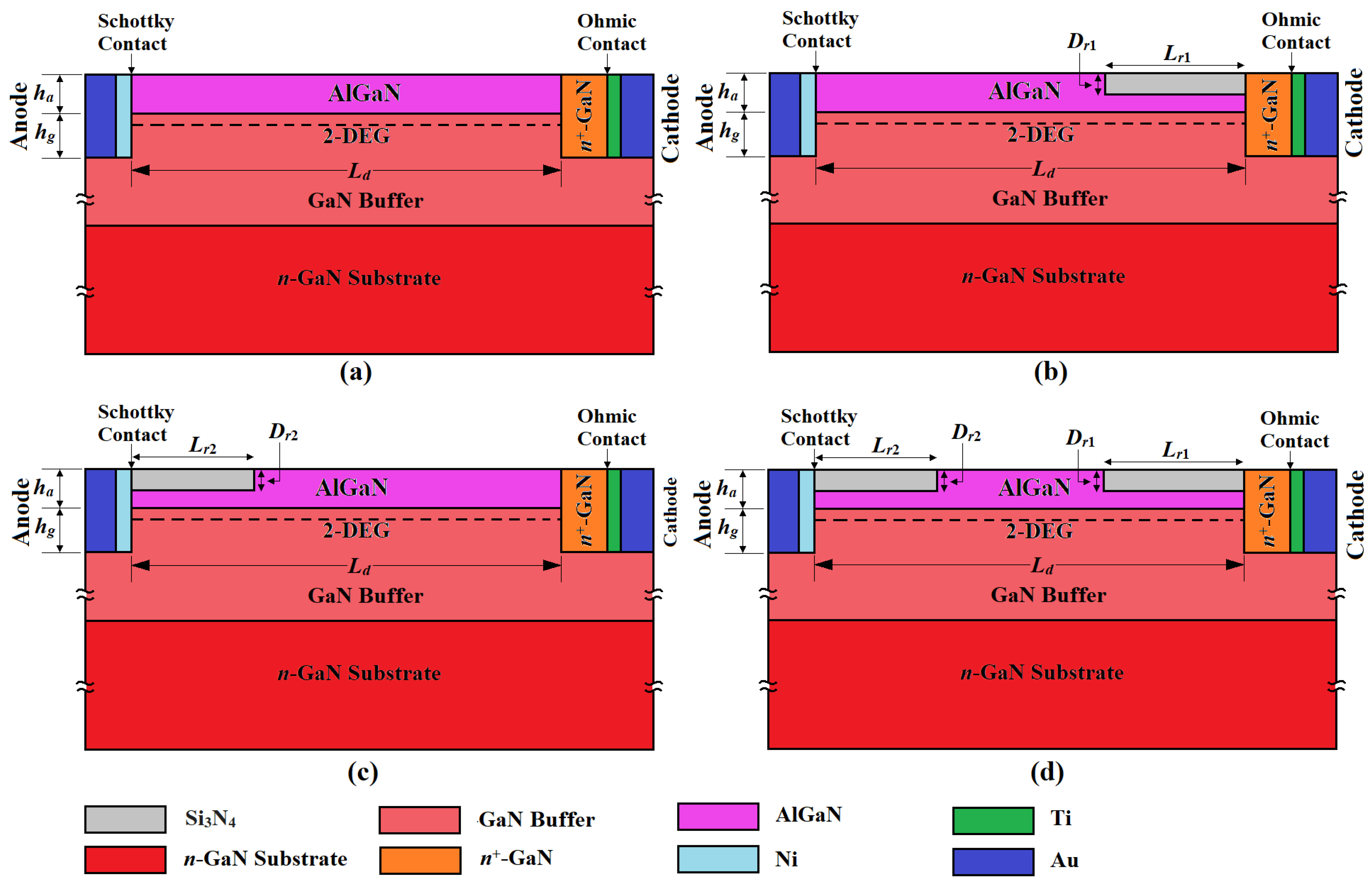
Figure 1. Cross-sectional view of (a) flat, (b) high–low (hi-lo), (c) low–high (lo-hi), and (d) low-high–low (lo-hi-lo) profile Schottky barrier lateral HEM-ATT structures; doping concentration on the n+-GaN layer is 4.0 × 1024 m−3.
Photonics 10 00800 g001
Figure 2. Two-dimensional simulation model for the lateral SDR Schottky barrier quasi-Read HEM-ATT structure.
Photonics 10 00800 g002
Figure 3. Two-dimensional simulation model for the vertical SDR Schottky barrier quasi-Read IMPATT structure.
Photonics 10 00800 g003
Figure 4. Two-dimensional simulation model for the vertical DDR quasi-Read IMPATT structure.
Photonics 10 00800 g004
Figure 5. Flowchart of the complete simulation program.
Photonics 10 00800 g005
Figure 6. Partial electron distribution introduced by polarization-induced sheet charge at the AlGaN/GaN interface of (a) flat, (b) hi-lo, (c) lo-hi and (d) lo-hi-lo HEM-ATT diodes.
Photonics 10 00800 g006
Figure 7. Electric field profiles along the channel region at the AlGaN/GaN interface of the HEM-ATT diodes for the reverse bias current density of 11.5 × 10⁸ A m−2.
Photonics 10 00800 g007
Figure 8. Reverse bias I–V characteristics of flat and quasi-Read HEM-ATT diodes obtained from both simulation and experimental measurements.
Photonics 10 00800 g008
Figure 9. Admittance characteristics of the HEM-ATT diodes without considering the effect of series resistance obtained from the large-signal simulation for the bias current density of 11.5 × 10⁸ A m−2.
Photonics 10 00800 g009
Figure 10. Device resistance and reactance (a) without and (b) with considering the effect of series resistance versus bias current density plots of the HEM-ATT diodes obtained from the large-signal simulation; variations in (c) RF power output and (d) DC to RF conversion efficiency with the bias current density obtained from the large-signal simulation.
Photonics 10 00800 g010
Figure 11. Variation in THz power output of the flat and quasi-Read HEM-ATTs, vertical Schottky IMAPTT and vertical GaN DDR IMPATT sources predicted by the large-signal simulation with frequency; inset of the figure shows the variation in DC to THz conversion efficiency of the THz sources under consideration obtained from large-signal simulation with frequency.
Photonics 10 00800 g011
Figure 12. Variation in noise spectral density of the THz sources with frequency; the inset of the figure illustrates enlarged view of the noise spectral density vs. frequency plots within the frequency range under consideration (0.8–1.2 THz).
Photonics 10 00800 g012
Figure 13. Variation in noise measure of the THz sources with frequency.
Photonics 10 00800 g013
Table 1. Structural parameters.
ParametersFlat HEM-ATThi-lo HEM-ATTlo-hi HEM-ATTlo-hi-lo HEM-ATT
Ld (nm)200200200200
Ln+ (nm)100100100100
ha (nm)20202020
hg (nm)20202020
LNi(Sch) (nm)20202020
LAu(Sch) (nm)100100100100
LTi(Oh) (nm)30303030
LAu(Oh) (nm)150150150150
Dr1 (nm)-10-10
Lr1 (nm)-50-50
Dr2 (nm)--1010
Lr2 (nm)--5050
Wd (μm)50505050
Table 2. List of some state-of-the-art THz sources (operating frequency ≈ 1.0 THz).
Sl. No.Type of the SourceImportant SpecificationsOperational Frequency Range (THz)THz Power Output (W)DC to THz
Conversion
Efficiency (%)
Citation
1Schottky barrier lateral HEM-ATT sourceBased on AlGaN/GaN two-dimensional electron gas0.923–1.0660.25–0.3011–25Present work
2Carcinotron-0.852 × 10⁻³-[80]
3Folded waveguide source-0.6559 × 10⁻³-[81]
4Backward wave oscillatorNarrow corrugated waveguide as slow wave structure0.85–1.030.20-[82]
5Backward wave oscillatorVane circuit using 20 mA of current at 7.1 KV, made by milling0.80–0.962.0 × 10−3<1.0[83]
6Backward wave oscillator6 KV, 60 A, 15 kg BWO, water-cooled1.03–1.250.5 × 10−3–2.0 × 10⁻³<1.0[84]
7Backward wave oscillatorFrequency-multiplied BWOs1.10–1.501.0 × 10−6<1.0[82]
8Backward wave oscillator10 MHz linewidth, semioptical-BWO hybrid devices, 6 KV cathodes, CW devices1.20–1.400.2 × 10−3<1.0[82]
9Quantum cascade laser (QCL)Monolithic THz source comprises 13.7 QCL coupled with a high-resistivity Si lens0.60–6.000.2 × 10−3-[85]
10Quantum cascade laser (QCL)Electrically pumped monolithic source based on long-wavelength dual-upper-state active region 1.031.8 × 10−5-[86]
11Quantum cascade laser (QCL)Electrically pumped monolithic semiconductor source with intra-cavity non-linear frequency mixing 1.2–5.9 2.87 × 10⁻³ at 1.5 THz (110 K temperature)<1.0[87]
12High-electron-mobility transistor (HEMT)Tunable room temperature source utilizes the two-dimensional plasma insability in GaN HEMTs0.75–2.2 0.15 × 10⁻⁶<1.0[88]
13Planner Schottky diode multipliers-1.75–2.0 0.40 × 10⁻⁴<1.0[89]
14Harmonic oscillator arraySi-based fully scalable coherent harmonic oscillator array1.010.81 × 10−40.73 × 10⁻⁴[90]
Disclaimer/Publisher’s Note: The statements, opinions and data contained in all publications are solely those of the individual author(s) and contributor(s) and not of MDPI and/or the editor(s). MDPI and/or the editor(s) disclaim responsibility for any injury to people or property resulting from any ideas, methods, instructions or products referred to in the content.