Abstract
Free-space optical (FSO) communication is widely used in satellites, ships, aircraft, and ground stations due to its advantages of high speed, large capacity, good confidentiality, and strong anti-interference ability. Variable-beam divergence angle (VBDA) technology makes FSO systems more flexible; this has the benefits of higher acquisition probability, stronger tracking ability, wider communication link range, and lower energy consumption. In other words, the study of VBDA has both theoretical significance and practical relevance. This paper conducts a comprehensive search of relevant scientific databases, journals, conference proceedings, patents, and books to identify publications related to VBDA technology. We analyze these publications, classify and organize various VBDA techniques based on their respective methods. To the best of our knowledge, this is the first review of VBDA technology. In this paper, we first explain the basic principle of changing the beam divergence angle by employing the ABCD matrix, and further furnish a detailed overview of the methods used for VBDA along with their corresponding advantages and disadvantages. In addition, we provide a comprehensive summary of the research conducted using VBDA technology across different link types. Lastly, we identify the challenges and potential future research directions for VBDA technology.
1. Introduction
Compared to 5G, 6G will use more advanced communication technology to support faster and wider communication scenarios [1,2], as shown in Figure 1. As the demand for data transmission and communication increases during the development of 6G, a large number of base stations will be required to support the expanding networks. Traditional base stations may not meet the requirements of high speed and large capacity communication that 6G demands. Therefore, new technologies and methods need to be explored to fulfill these requirements. In this case, free-space optical (FSO) communication technology is a viable solution, as it can significantly improve the performance and reliability of communication networks [3,4]. In particular, when building 6G networks in remote areas, deploying traditional base stations may not be practical or may be too costly. Therefore, FSO can be used to relay communication signals through satellites, high-altitude platforms (HAP), unmanned aerial vehicles (UAV), and other means to achieve seamless connections across long distances, thereby improving the coverage and availability of 6G networks for users in rural and remote areas.
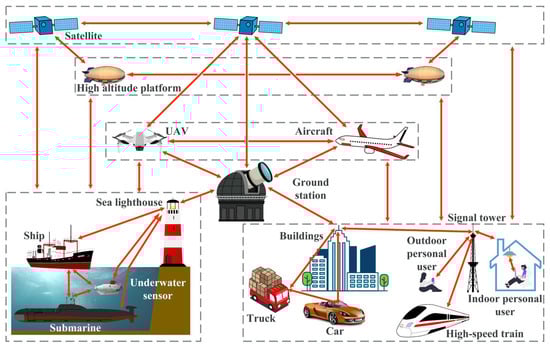
Figure 1.
The extensive communication scenario contained in 6G.
Thus, FSO technology will occupy a significant proportion of 6G communication technology and become one of the driving forces in the development of 6G technology. Its application will help address the bandwidth and rate bottlenecks faced by current 5G networks, and lay the foundation for faster, smarter, and more reliable communication services in the future.
Taking the intensity modulation/direct detection (IM/DD) with on-off keying (OOK) FSO communication system as an example, Figure 2 illustrates its typical optical path. A laser diode (LD) is commonly used as the light source, although some manufacturers may use high-power LEDs [5]. At the transmitting end, the data is encoded and modulated [6]. The modulated light beam is then amplified and shaped by an optical amplifier, collimator, and optical antenna before entering free space. At the receiving end, the optical antenna focuses the received beam onto an optoelectronics diode (PD), which converts the received optical signal into electrical current. Finally, the demodulation process is performed to obtain the original transmission data.
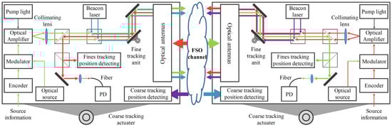
Figure 2.
Optical path diagram of FSO communication terminal.
At present, FSO communications mostly use fixed-beam divergent angle scheme. It has several benefits, such as a wide selection of commercial components, compact structure, and ease of installation. However, there is still room for improvement in areas such as link reliability, communication link range, and power consumption [7]. Compared to fixed-beam divergent angle scheme, the variable-beam divergent angle (VBDA) scheme offers four significant advantages, which are illustrated in Figure 3. Each of these advantages will be discussed in detail below:
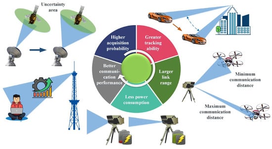
Figure 3.
Advantages of FSO communication systems with VBDA scheme.
Higher acquisition probability. When targeting objects with a large uncertain area (such as targets moving at high speeds or drifting due to Global Positioning System (GPS) unavailability), traditional solutions involve using a large divergence angle beam to cover the uncertain area or scanning with a small divergence angle beam. However, these methods have drawbacks, such as reduced detection range or increased acquisition time. To address this problem, a solution using VBDA can be employed. As in [8], the beam divergence angle θ is set to 1/(2𝜙 + 1) times the size of the uncertain area, whose angle value is θ0, as shown in Figure 4. Here, 𝜙 = 0, 1, 2, … represents the scanning phase, and scanning starts from the 𝜙 = 0 phase. If the beam is not detected, the system enters the next phase and continues to scan. At this time, 𝜙 = 1, and the value of θ becomes θ0/(2 × 1 + 1). This process is repeated until the receiver detects the beam and starts tracking. Simulation results demonstrate that this new scanning strategy reduces acquisition time by approximately 80%, leading to a significant improvement in the probability of acquisition.
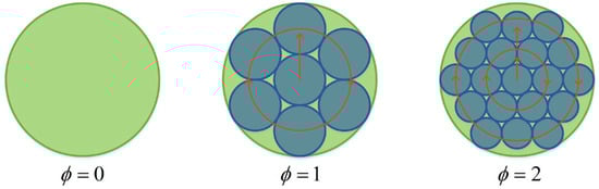
Figure 4.
The acquisition strategy of using VBDA scheme [8]. Reprinted/adapted with permission from Ref. [8]. 2017, SPIE.
Greater tracking ability. Upon entering the tracking phase, the beam divergence angle can be further compressed by utilizing information from the coarse and fine tracking residuals. This results in improved optical power received by the coarse and fine tracking units, typically cameras and four quadrant detectors, respectively. The increase in optical power enhances the tracking ability. When coarse and fine tracking residuals increase due to turbulence or jitter in platform itself, appropriately increasing the beam divergence angle can improve the robustness of the coarse and fine tracking units to these disturbances, leading to more reliable communication due to an enlarged allowable pointing error.
Larger communication link range. In certain 6G use cases, the distance between FSO nodes would dynamically change [9], such as for communication between ground stations and UAVs. When the communication distance decreases, the beam radius has not yet significantly expanded, resulting in a smaller allowable pointing error. Consequently, the pointing error occurring during the beam steering interval easily exceeds the allowable limit. This indicates that the FSO link is more likely to be disconnected as the moving node approaches its paired node. To address this, appropriately increasing the beam divergence angle can effectively cover the uncertain area, thereby potentially reducing the minimum communication distance.
When the communication distance increases, the optical power loss increases by 6 dB every time the communication distance doubles [10]. Although it could be compensated for by a larger receiving aperture or higher transmission power, these compensation methods are very limited because a larger aperture or higher power light source will increase the SWaP (size, weight, and power) requirements of the optical system [11]. At this time, appropriately reducing the beam divergence angle can increase the received optical power, thereby further increasing the maximum communication distance. In summary, the use of a VBDA scheme could effectively increase the FSO communication link range.
Less power consumption. Fixed-beam divergence angle systems are often designed based on the worst-case scenario. In addition, the beam divergence angle will be slightly larger than the optimal beam divergence angle (OBDA) during communication, which results in a certain amount of energy waste. In applications where energy consumption is a critical factor, such as in satellites, UAVs, and personal handheld terminals, it is desirable to reduce unnecessary energy waste to extend the equipment’s endurance time. By selecting the appropriate beam divergence angle and optical power based on real-time link conditions, it is possible to reduce energy consumption while maintaining communication rates.
Better communication performance. During FSO communication, the performance of the link can be influenced by various factors. These include system parameters such as beam divergence angle, transmitted optical power, receiver’s field of view (FOV) angle, attenuation loss, atmospheric turbulence, pointing error, and angle-of-arrival (AOA) fluctuations. By adjusting the beam divergence angle and transmitted optical power, improved communication performance can be attained, resulting in lower outage probability (OP) and bit error rate (BER). In the existing studies, considering the aforementioned influencing factors, closed-form expressions of communication performance metrics such as OP and BER have been derived and simulated. This was achieved by deriving the expressions of probability density function (PDF) and cumulative distribution function (CDF) under different channel fading models, such as K distribution [12,13], Log-Normal distribution [14,15], distribution [16,17,18,19], and generalized Málaga distribution [20,21], etc. The results demonstrate a strong dependence of performance indices on adjustable system parameters, such as beam divergence angle, transmitted optical power, and receiver’s FOV angle [14,21,22,23]. Additionally, the OBDA varies with different factors, such as transmitted optical power [14,21,24,25,26,27]. Therefore, VBDA technology can facilitate achieving better communication performance.
In this paper, leveraging over 10 years of extensive experience in FSO communication [28,29,30,31,32,33,34], we present a comprehensive review of VBDA technology. To the best of our knowledge, this is the first review of VBDA technology. Distinguishing itself from previous studies, which focused on specific VBDA methods, this review classifies and organizes various VBDA techniques according to their respective methods, while summarizing the advantages and disadvantages of each method. By providing this comprehensive analysis, we aim to enhance the overall understanding of VBDA methods. The structure of this paper is as follows: Section 1 introduces the demand for FSO communication in the development of 6G, the basic structure of FSO communication systems, and the advantages of VBDA scheme; Section 2 introduces the transmission theory of the Gaussian beam and the basic optical principles of the VBDA method; and Section 3 provides a comprehensive overview of the currently employed VBDA methods, highlighting their respective advantages and disadvantages in detail. Additionally, the paper summarizes research on the utilization of VBDA technologies for different types of links. Finally, the challenges and possible future research directions of VBDA technology are summarized.
2. Optical Principle of VBDA Method
Single-mode fiber (SMF) has been widely used in FSO communication due to its advantages of low attenuation, low dispersion, and high-bandwidth capacity. Since the beam emitted in SMF can be approximated as a fundamental mode Gaussian beam, the transmission theory of Gaussian beams is used to analyze the principle of VBDA. Assume that the SMF emits a Gaussian beam with a waist radius of , which is located on the end face of SMF, as shown in Figure 5. The ideal single lens is placed at a distance of from the source, has a focal length of , and transforms the Gaussian beam into an outgoing beam with a waist radius of . The distance from the rear surface of the lens to the outgoing beam waist is denoted as . The parameters of the incident Gaussian beam at the waist and at the rear surface of the lens are denoted as and , respectively. In the following analysis, we will use the ABCD law of Gaussian beam propagation [35] to determine the divergence angle of the outgoing beam.
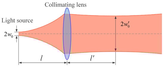
Figure 5.
Characteristic schematic diagram of the basic Gaussian beam after lens transformation.
The parameter of incident Gaussian beam is:
The ABCD matrix transmitted from the waist of the incident Gaussian beam to the front surface of the lens is given by . The ABCD matrix transmitted from the front surface of the lens to the rear surface of the lens is . By the ABCD law, the ABCD transmission matrix from the beam waist position of the incident Gaussian beam to the rear surface of the lens is given by:
The parameter of Gaussian beam at the rear surface of the lens can be obtained as follows:
And the parameter of Gaussian beam at the rear surface of the lens is:
So:
The solution is:
According to the calculation formula , the far-field divergence angle of a Gaussian beam can be obtained as follows:
The outgoing beam divergence angle is minimized when , i.e., when the beam waist is positioned at the front focal plane of the collimating lens. This corresponds to the state of optimal collimation. As a result, the outgoing beam exhibits a minimized divergence angle of . According to Equation (7), any changes in the values of , , or will result in changes to the divergence angle of the outgoing beam. Since the mode field radius of SMF at a specific wavelength cannot be easily modified, the divergence angle of the exit beam can be altered by adjusting the focal length of the collimating lens or by varying the distance between the SMF end face and the collimating lens. The influence of and on the divergence angle of the outgoing beam is shown in Figure 6.
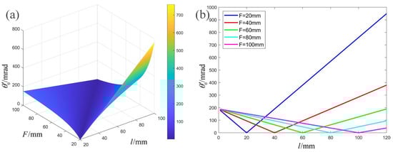
Figure 6.
(a) The divergence angle versus and . (b) The divergence angle versus with different values of .
Furthermore, one way to change is by altering the optical path length between the SMF end face and collimating lens. For example, one can insert a parallel flat glass as shown in Figure 7, which alters the ABCD matrix. The ABCD matrix transmitted from the waist of the incident Gaussian beam to the front surface of the plate is . The ABCD matrix transmitted from the front surface of the plate to the back surface of the plate is . The ABCD matrix transmitted from the back surface of the plate to the front surface of the lens is .
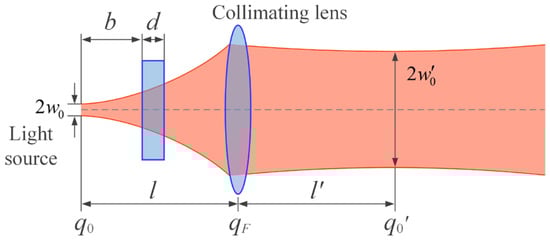
Figure 7.
Schematic diagram of the method for changing the optical path length between the light source and the collimating lens.
Therefore, the ABCD transmission matrix from the beam waist position of the incident Gaussian beam to the rear surface of the lens is changed to:
Substituting this into Equation (3), we obtain:
The solution is:
Substituting this into , we obtain:
According to Equation (11), altering the refractive index or thickness of the parallel flat glass can change the divergence angle of the outgoing beam, as shown in Figure 8.
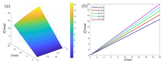
Figure 8.
(a) The divergence angle versus and . (b) The divergence angle versus with different values of .
As mentioned above, the divergence angle of the outgoing beam can be modified by adjusting the focal length of the collimating lens or the optical path length between the beam waist and the collimating lens. Based on these two categories, the existing techniques for achieving VBDA are classified and depicted in Figure 9. The following sections provide a detailed description of these methods.
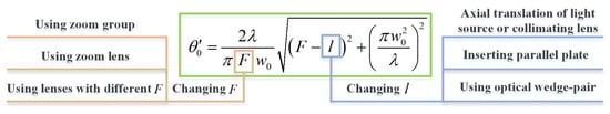
Figure 9.
Existing methods of varying divergence angle.
3. Existing Methods for VBDA
In this section, we will delve into the two main VBDA methods. We will highlight how each method works, how it is implemented, and its pros and cons. With a thorough examination of these methods, readers will be able to better understand the two main VBDA methods and choose the technique that best suits their application scenarios.
3.1. Vary Beam Divergence by Adjusting the Focal Length F of the Collimating Lens
3.1.1. Using Zoom Group
Figure 10 illustrates the operating principle, which involves adjusting the distance between two or more zoom lenses to alter the focal length of the lens group, subsequently changing the beam divergence angle. The technique offers several advantages, including a wide range of continuous divergence angle changes and the relatively mature technology of the zoom lens group. However, designing a zoom lens group with a large zoom ratio is costly, and high-quality guide rails or actuators are necessary, which can be a potential disadvantage.
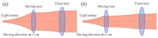
Figure 10.
The principal diagram of VBDA by using zoom group. (a) Collimation state, (b) Large divergence angle state.
The research on this method is as follows: K.K. Han [36] and J.J. Ma et al. [37] used two positive lenses combined as a VBDA mechanism. Y.L. Yang et al. [38] varied the beam divergence angle from 0.7 mrad to 1.2 mrad by moving the rod lens connected with optical fiber along the axial direction. X.L. Xie et al. [39] designed a VBDA mechanism by altering the distance between the primary mirror and the secondary mirror of a Cassegrin transmitting antenna. The VBDA mechanism designed and fabricated by A. Carrasco-Casado et al. [40] is shown in Figure 11. Its beam divergence angle can be continuously adjusted between 90 and 6250 μrad (full width at half maximum, FWHM), with optical axis stability of less than 5% during the transformation process. The system’s optical aberrations were evaluated using a shear interferometer, and the outgoing beam exhibited good wavefront quality.
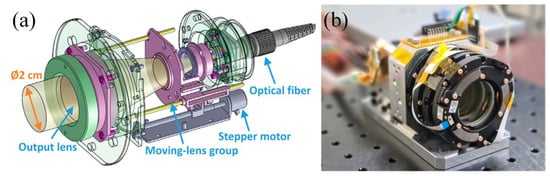
Figure 11.
(a) 3D model of the beam divergence angle control system, (b) first prototype of the beam divergence angle control system [40]. Reprinted/adapted with permission from Ref. [40]. 2022, Carrasco-Casado, A.
3.1.2. Using Zoom Lens
This method involves using the adjustable focal length of a liquid lens to introduce defocus and change the beam divergence angle. At present, there are three types of liquid lenses commonly used:
Electro-wetting liquid lens. Figure 12a shows the cavity of this liquid lens, which contains two liquids of similar density and mutually insoluble. The liquid–liquid contact surface forms a refractive surface [41,42], and the radius of curvature of the surface can be changed by voltage, thereby changing the focal length. The advantage of using it to change the beam divergence angle is that the principle is simple, the zoom range is large, and no mechanical displacement element is needed. Additionally, it can spontaneously form lenses with very high-surface quality. However, it also faces the challenge of difficulty in making the aperture larger. When the lens aperture is greater than 5 mm, the wavefront aberration caused by gravity becomes non-negligible [43].
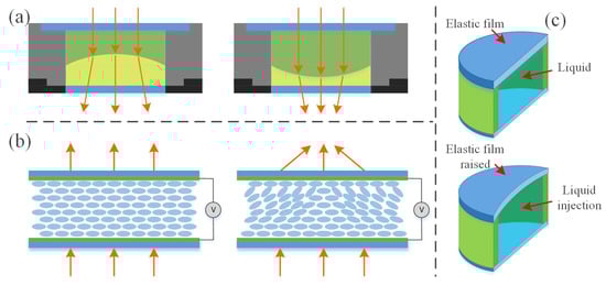
Figure 12.
Working principal diagram of liquid lens. (a) Electro-wetting liquid lens. (b) Liquid crystal material liquid lens. (c) Mechanical hydraulic-driven liquid lens.
Liquid crystal material liquid lens. By applying a voltage to a specially shaped electrode, the liquid lens generates a gradient-varying electric field which changes the refractive index and focal length of the lens [44,45], as shown in Figure 12b. One advantage of it is that the liquid crystal layer can be made very thin, down to tens of μm. And the required driving voltage is small. However, the lens is usually used with a polarizer, which results in low light transmittance and makes it unsuitable for high-power laser applications.
Mechanical hydraulic-driven liquid lens. Typically, this technique involves confining the liquid within a closed cavity using a stretchable elastic film [46,47], as shown in Figure 12c. By applying external pressure to change the curvature radius of the elastic film, the focal length of the liquid lens can be changed. One advantage of it is its short response time. However, its disadvantage is that the rough surface of the elastic film would affect light transmittance, the uneven deformation of the film layer would reduce image quality, and the outer surface of the elastic film is prone to absorbing dust and other small particles.
Overall, using a liquid lens to change the beam divergence angle has several advantages, including a short response time, a large variation range for the divergence angle, a simple structure, and the ability to reduce the mechanical actuator and terminal volume. However, it also faces the challenge of the difficulty of making the aperture larger. Therefore, liquid lenses with larger apertures are best used in vertical and downward positions and are not suitable for rotation with a turntable.
A. J. Williams et al. [48] and V. V. Mai et al. [49] used liquid lenses to change beam divergence angles. M. ZOHRABI et al. [50] used three mechanical hydraulic liquid lenses in combination with wide-angle fisheye lenses to achieve 2D beam scanning of ±75°, as shown in Figure 13. Tunable liquid lens 1 was used to maintain the beam divergence angle while tunable liquid lens 2 and tunable liquid lens 3 were decentered in the Y and X directions, respectively, acting as prisms to control the beam deflection angle. V. V. Mai et al. [51] also used three liquid lenses to achieve adaptive control of beam steering and divergence angle, as shown in the inset of Figure 14, called VFL system. The authors found that deterioration of the beam quality can be clearly observed when the liquid lens is aligned horizontally. Therefore, a vertical arrangement of the liquid lens was suggested. Later V. V. Mai et al. [52,53,54] used the above system to perform an experimental demonstration of wavelength-division-multiplexing (WDM) transmission, as shown in Figure 14. The channel spacing of WDM is 0.8 nm, and the four communication wavelengths are 1549.2 nm, 1550 nm, 1550.8 nm, and 1551.6 nm, respectively. It was the first study on a WDM FSO system capable of non-mechanical optical beam steering and divergence control realized by liquid lenses.
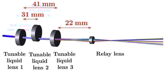
Figure 13.
The schematic of the full 2D scan setup [50]. Reprinted/adapted with permission from Ref. [50]. 2016, The Optical Society.
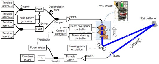
Figure 14.
Experimental light path diagram of WDM based on liquid lens beam steering and divergence angle control system [53]. Reprinted/adapted with permission from Ref. [53]. 2022, Kim, H.
3.1.3. Using Lens with Different F
This method of VBDA can switch between small and large angles. There are two main ways to do this: switching collimators with different focal lengths or inserting different defocus lenses, as shown in Figure 15. Figure 15a demonstrates the use of an optical switch to select a collimator with a different focal length for transmitting the beam. K. H. Heng et al. [55] used this method to change the beam divergence angle.
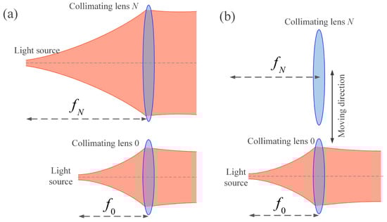
Figure 15.
Schematic diagram of VBDA method by: (a) switching collimators with different focal lengths. (b) inserting different defocus lenses.
Figure 15b shows lenses with different focal lengths that are moved to the optical axis using an electric drive. Y. Hu et al. [56] used this method. N. Yang et al. [57] fixed multiple collimating lenses with different focal lengths on a disk and switched between them by driving the rotation of the disk, achieving a graded and adjustable beam divergence angle.
This VBDA method has the advantage of a simple principle and easy operation. However, its disadvantage lies in the high requirements for repeated positioning accuracy of the electric displacement mechanism. Failure to meet these requirements may result in significant beam drift. This method can only be used in grades and cannot continuously change the divergence angle. Furthermore, the communication link will experience an outage when the divergence angle is switched.
3.2. Vary Beam Divergence by Adjusting the Optical Path Length between the Beam Waist and the Collimating Lens
3.2.1. Axial Translation of Light Source or Collimating Lens
Figure 16 is the schematic diagram of this method. (Note that the mode field diameter of a normal 1550 nm SMF is only about 10.4 μm and is exaggerated for convenience in this and the following figures). The lens or light source is fixed on a linear electric stage, which adjusts the beam divergence angle by changing the distance between the light source and the collimating lens. This method has the advantages of a simple principle and device and could achieve a large range of divergence angle changes. The risk of introducing additional wavefront distortion is reduced because no extra zoom elements are inserted into the optical path. Despite its benefits, this method has a notable disadvantage; it demands an exceptionally high level of parallelism in the linear electric stage. In [58], it was suggested that the lateral motion (eccentricity) of the lens or light source should not exceed 3 μm.
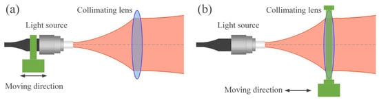
Figure 16.
Schematic diagram of VBDA by axial translation light source or collimating lens (a) Moving light source. (b) Moving collimating lens.
Previous studies [57,59,60,61,62,63,64] adjusted the beam divergence angle by moving the light source, while only [65] moved the lens. The light source, often a fiber head of a SMF, is smaller and easier to manipulate than collimating lenses, making it a more popular choice in experiments.
By using this VBDA method, N. Yang et al. [57] and L. Zhu et al. [60] achieved the beaconless acquisition function of an FSO system. C.M. Kelway [59] and V. Gianfranco et al. [61] mitigated the influence of different atmospheric attenuation on the received optical power. J. Ma et al. [62] designed a satellite FSO communication terminal test device with VBDA. Refs. [63,64,65] improved optical tracking characteristics. The VBDA mechanism and its FSO terminal, as presented in [63], are shown in Figure 17.
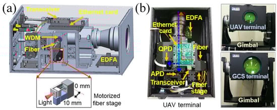
Figure 17.
(a) FSO terminal and its VBDA mechanism. (b) Prototype of FSO communication terminal principle [63]. Reprinted/adapted with permission from Ref. [63]. 2021, Elsevier.
3.2.2. Inserting Parallel Plate
The schematic diagram in Figure 18 illustrates the method. A motor drives a parallel plate glass to insert into the optical path, thereby altering the optical path length between the light source and the collimating lens. This enables the switch between small and large divergence angles. The advantages of this method are its simplicity in principle and ability to greatly relax the requirement for lateral positioning accuracy. Additionally, it does not require precise location determination, so the mechanical properties of the motor driver can be simple and economical. However, the method cannot continuously change the divergence angle, and switching between large and small divergence angles introduces scintillation, which causes the link to experience an outage during insertion time.
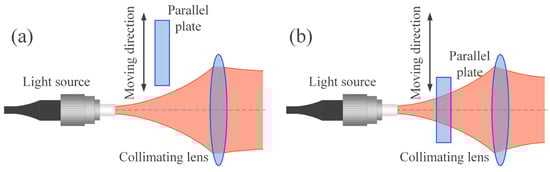
Figure 18.
Schematic diagram of VBDA achieved by inserting a parallel plate. (a) Collimation state. (b) Large divergence angle state.
G.A. Mitchell [66] applied this method to pickup and camera systems, enabling quick and easy focusing between different film surfaces by moving in and out of parallel plate glass. In the context of laser communication systems, this method can be implemented using a group of parallel plates of varying thickness. The plates can be selected and moved into the optical path by electric actuators, allowing for different beam divergence angles to be achieved by using plates of different thickness or by simultaneously selecting multiple plates.
3.2.3. Using Optical Wedge Pair
The schematic diagram in Figure 19 shows the optical wedge pair used in the optical path, where the thickness of the pair is adjusted by adjusting the moving optical wedge to change the beam divergence angle. This method offers several advantages, including a wide range of divergence angle changes, low impact on the optical axis deflection during adjustment, and a large tolerance for lateral positioning errors. This method requires a tradeoff between the range of VBDA and wavefront aberrations. If the wedge angle is reduced, the range of VBDA will be narrowed. Conversely, if the wedge angle is increased, astigmatism will be introduced, causing the outgoing beam to become oval.
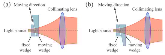
Figure 19.
Schematic diagram of the VBDA method using wedge-pair. (a) Collimation state. (b) Large divergence angle state.
R.F. Schuma et al. [67] used a set of optical wedge pair of the same size between two lens groups in the beam expander to achieve the function of VBDA. M.H. Keith et al. [58] placed the wedge pair in front of the collimating lens and achieved continuous adjustment of the beam divergence angle between 38 μrad and 300 μrad (full width at half maximum (FWHM)), as shown in the green dotted box in Figure 20. Building upon this mechanism, J.M. Roth et al. [68] designed and manufactured a FSO communication system with continuously adjustable beam divergence angle and optical power, also shown in Figure 20. To minimize the terminal SWaP, the beacon and signal beams (at different wavelengths) were amplified by the same HPOA, and the relative power level of each beam was dynamically controlled using an electronically controlled variable optical attenuator (VOA).
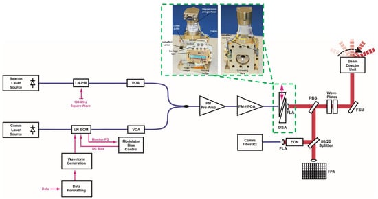
Figure 20.
Optical path diagram of FSO communication system with continuously adjustable beam divergence angle and optical power [58,68]. Reprinted/adapted with permission from Ref. [58]. 2015, SPIE. Reprinted/adapted with permission from Ref. [68]. 2019, Roth, J.M.
In summary, we have thoroughly investigated various VBDA methods in FSO communication systems. The key parameters of all current VBDA mechanisms in Table 1, including the wavelength, range of beam divergence angles, power range, communication distance, data rate, and bit error rate (BER). Moreover, we have assessed the advantages and disadvantages of different VBDA methods and compiled them in Table 2. This comprehensive overview can help designers and researchers compare and evaluate the performance of different VBDA techniques for various FSO applications. By highlighting the benefits and limitations of each method, we aim to provide readers with a clear understanding of the trade-offs involved in selecting a particular VBDA technique.

Table 1.
Summary of variable-beam diverging angle methods.
Table 2.
Summary of the characteristics of several methods of VBDA.
Furthermore, we have presented Table 3, which summarizes the current studies that have applied VBDA technology to different link types, such as ground terminal platforms, air platforms, high-speed train (HST) platforms, underwater platforms, and satellite platforms. It is worth noting that each VBDA method described in this paper has its unique characteristics, and designers should choose the appropriate technique for the given FSO link situation and communication terminal conditions. Factors such as power consumption, beam quality, cost, and environmental robustness must be carefully considered when selecting a VBDA method. We hope that the comprehensive analysis and discussion in this paper will contribute to the advancement of VBDA technology and its successful integration into practical FSO systems.
Table 3.
The platform/link types have applied VBDA technology.
4. Challenges and Future Work
This paper provides a comprehensive overview of various VBDA methods used in FSO communication, focusing on the advantages and disadvantages of different methods. It also sorts out the research on the use of VBDA methods for different link types. Despite significant advances in VBDA technology, several challenges still remain. To address these challenges, we propose several promising research directions and provide potential measures for overcoming these challenges, which will be discussed below.
4.1. Reduce the Computational Cost of OBDA
Computing the OBDA involves complex mathematical calculations and requires a large amount of computing resources, which would consume considerable power. This presents a significant challenge for FSO communication remote nodes with limited SWaP budgets. To promote the widespread adoption of FSO communication on various platforms, the computational cost of OBDA must be reduced to some extent. Potential measures for overcoming this challenge are shown below:
- Algorithm Optimization: Use different algorithms of varying complexity to compute the OBDA for different types of terminals. Large communication terminals, such as ground stations, can use relatively complex and advanced OBDA algorithms due to their high tolerance for high computing costs. For remote small units, relatively simple OBDA algorithms can be used, and the computational accuracy can be appropriately reduced to alleviate the computational pressure;
- Distributed Computing: Assign the task of computing the OBDA for each communication party to a node with powerful computing capabilities. And the computing results are then transmitted to the remote communication node via FSO communication or RF link. This measure could reduce the computational burden and power consumption of small communication nodes. However, it introduces additional delay. Therefore, it is essential to comprehensively consider the capabilities of terminal and relay equipment, communication environment, and application requirements to achieve optimal performance and efficiency;
- Machine Learning Techniques: Utilize machine learning to improve the accuracy and efficiency of the OBDA algorithm. By leveraging the complex relationship between the link factors and OBDA, machine learning can improve accuracy and efficiency, resulting in reduced computational costs. In addition, neural network hardware accelerators combined with field-programmable gate array (FPGA) can be reconfigured for different target applications while maintaining low power consumption. This measure leverages the ability of FPGA parallel computing to achieve low-delay processing.
By implementing these measures, the computational cost of OBDA can be reduced, leading to lower power consumption. This can enable FSO communication on platforms with limited power supplies and facilitate its proliferation in various scenarios, such as military operations, disaster relief, and remote sensing applications.
4.2. Achieve Better Reliability and Environmental Adaptability
FSO communication terminals must operate in a wide range of environments, including varying temperatures, humidity levels, and vibrations. As a result, there are high expectations for the reliability and adaptability of the VBDA system. Temperature, in particular, is a crucial factor that affects the system’s performance. For instance, reference [40] reported that the beam’s divergence angle was 7.5 times wider than expected at −30 °C and 4.7 times wider than expected at 60 °C. Therefore, designing and manufacturing a VBDA mechanism with strong environmental adaptability and temperature insensitivity is of great significance. Various measures can be used to achieve this goal, such as:
- Reducing the impact of temperature: There are two ways to approach this issue. ① Selecting materials with low thermal expansion coefficients. This helps to maintain the stability and performance of the VBDA mechanism across a wide range of temperatures. ② Adding a temperature compensation mechanism. This compensates for any thermal-induced changes, ensuring the VBDA mechanism remains within the appropriate temperature range;
- Real-time measurement of transmitted beam divergence angle: By continuously measuring the beam divergence angle in real time, feedback can be provided to the VBDA mechanism. This feedback can be adjusted immediately to compensate for changes caused by temperature fluctuations, ensuring accurate beam alignment and reliable communication;
- Performing temperature tests and creating a lookup table: Conducting temperature tests on the VBDA mechanism helps to understand its performance characteristics under different temperature conditions. Based on the results, a lookup table can be created that maps temperature variations to the corresponding correction values for the beam divergence angle. This lookup table can then be used to apply real-time corrections during operation, compensating for the effects of temperature changes.
These examples demonstrate various approaches to enhance the reliability and environmental adaptability of the VBDA mechanism in FSO communication terminals. By implementing such measures, the performance of the system can be improved, resulting in more effective and dependable communication capabilities.
4.3. Reduce Hardware Costs
While VBDA technology has been successfully verified in experiments [8,38,40,49,50,51,52,53,54,56,58,63,64,65,68], it has not yet been commercialized on a large scale. Therefore, it is necessary to consider the challenges and opportunities associated with scaling up the technology. One critical factor in making this technology more accessible and appealing to potential users is to reduce its cost. Several measures can be employed to achieve this goal.
- Modular design: Implement a modular design for the VBDA system, where different components are divided into modules that can be easily replaced when a failure occurs. This can significantly reduce the cost of maintenance and repair, improving the system’s overall maintainability. Additionally, by adding new modules, the system’s functionality can be easily extended without significantly affecting its overall design. This makes the system more adaptable and able to meet various application scenarios and requirements;
- Design for Manufacturing (DFM): The design should apply principles that prioritize ease of manufacturing and assembly. It should be simplified to reduce the number of complex parts and manufacturing steps. The use of materials should be optimized to minimize waste and lower production costs. It is important to ensure that the design is compatible with existing manufacturing processes and technologies, thereby avoiding the need for expensive production modifications;
- Utilize commercially manufactured components: Consider using commercially available components to minimize the number of unique parts needed. This can significantly reduce the costs and time associated with producing custom components. Commercial components are often mass produced and have established quality standards, which ensure the reliability and consistency of the final product.
It is important to note that reducing the cost of this technology should not come at the expense of its quality and performance. Maintaining a high standard of performance and reliability is essential to ensure that VBDA technology meets the needs and expectations of users. By addressing this challenge, researchers and industry professionals can unlock the potential of this innovative technology and create new opportunities for growth and innovation.
4.4. Other Future Trends
In addition to the above trends, VBDA technology can be combined with other technologies in FSO communication to achieve better performance. For example:
4.4.1. To Realize UAV Swarm Communication and Positioning under Electromagnetic Suppression Conditions
During UAV swarm flight on the battlefield, the communication and navigation systems may be disrupted by electromagnetic suppression, which may result in failure. To maintain the safety and stability of the swarm, the VBDA system can be used for communication and navigation at different distances. For instance, when swarm members are closer together, the beam divergence angle can be increased to cover uncertain areas. However, when the leader directs the swarm members to depart from the swarm to perform independent tasks, the beam divergence angle can be reduced to maintain communication under the increasing communication distance. This flexibility enhances the ability of UAV swarm to perform a wide range of operations.
4.4.2. Applied to Quantum Key Distribution (QKD)
VBDA technology can be applied to QKD to improve its performance. QKD is a novel cryptographic technique used to establish private encryption keys. One of the challenges of QKD is the loss of photons during transmission, which would reduce the signal-to-noise ratio (SNR) and transmission distance [96,97]. The use of VBDA can help reduce this loss by adjusting the beam divergence angle based on the communication distance and the link quality, thereby improving the received optical power. This can enable secure distribution of quantum keys over longer communication distances.
4.4.3. Applied to MIMO
Multiple-input multiple-output (MIMO) technology achieves diversity through the use of multiple-transmit and receive antennas, which improves the SNR at the receiver and minimizes the outage probability [98]. Because the impact of spot quality variations on the receiving end can vary significantly [99,100,101], VBDA technology can be applied to MIMO to adjust the beam divergence angle and optical power of multiple transmitting inputs, achieving a good compromise between link availability and communication rate. For example, the dartboard scheme proposed in reference [102] uses two concentric laser beams with different divergence angles for superposition, significantly improving the average data rate of the link. Simulations showed that, at 10 dBm transmit power, the dartboard scheme provides 53% higher data rate than 4-level pulse-amplitude modulation (4-PAM) and 79% higher than OOK. Therefore, VBDA technology can be applied to MIMO in FSO communication in the future to further improve the performance and reliability of the communication link.
5. Conclusions
This paper organizes a comprehensive overview of various VBDA techniques used in FSO communication. It mainly contains the following content:
- Explanation of the application significance of VBDA technology in FSO communication, emphasizing its ability to enhance system performance in terms of higher acquisition probability, greater tracking ability, larger communication link range, and lower power consumption;
- Introduction to the transmission theory of Gaussian beams and the basic principle of the VBDA method, laying the foundation for the following discussion;
- In-depth research on different types of VBDA methods, including:
- a.
- Using zoom groups or axial translation of fiber or lens: This method has the advantage of mature zoom lens groups technology and simple principles. However, it requires high-quality guide rails and actuators;
- b.
- Using zoom lenses: This method has the advantages of having no mechanical mechanism and being small in size, but the system may be affected by gravity, and enlarging the aperture may be difficult;
- c.
- Using lenses with different F or inserting parallel plates: These methods, respectively, have the advantage of simplicity and can greatly relax the requirement for lateral positioning accuracy. However, the communication link will experience an outage when switching angles;
- d.
- Using an optical wedge-pair: The advantage is that the influence on the optical axis deflection is small. However, a trade-off must be made between the VBDA range and larger astigmatism;
- e.
- The research on using VBDA technologies for different types of links and how they can enhance performance.
These characteristics require the appropriate choose of VBDA method for the given FSO link situation and communication terminal conditions. Factors such as power consumption, beam quality, cost, and environmental robustness must be carefully considered;
- 4.
- Emphasis on the challenges faced by VBDA technology and potential future research directions.
The comprehensive analysis and discussion provided in the paper aim to contribute to the advancement of VBDA technology and its successful integration into practical FSO systems.
Author Contributions
Writing—original draft preparation, G.Z.; writing—review and editing, G.Z., X.W., J.W., L.M., Y.L., X.Y., and S.G.; and supervision, S.G. All authors have read and agreed to the published version of the manuscript.
Funding
This work was supported by National Natural Science Foundation of China (No. 62101527), Funding Program of Innovation Labs by CIOMP (Y9J132E).
Institutional Review Board Statement
Not applicable.
Informed Consent Statement
Not applicable.
Data Availability Statement
Not applicable.
Acknowledgments
We would like to express our gratitude to https://pixabay.com (accessed on 1 May 2023), https://www.pexels.com (accessed on 1 May 2023), https://illlustrations.co (accessed on 1 May 2023), https://lukaszadam.com/illustrations (accessed on 3 May 2023), https://undraw.co/illustrations (accessed on 3 May 2023), https://www.flaticon.com/free-icon/analysis_10711078 (accessed on 7 May 2023), and https://www.manypixels.co (accessed on 5 May 2023) for providing the images used in this article. Their contributions greatly enhanced the visual presentation and overall quality of our work.
Conflicts of Interest
The authors declare no conflict of interest.
References
- Majumdar, A.K. Laser Communication with Constellation Satellites, UAVs, HAPs and Balloons: Fundamentals and Systems Analysis for Global Connectivity; Springer International Publishing: Cham, Switzerland, 2022; p. 48. ISBN 978-3-031-03971-3. [Google Scholar]
- Alraih, S.; Shayea, I.; Behjati, M.; Nordin, R.; Abdullah, N.F.; Abu-Samah, A.; Nandi, D. Revolution or Evolution? Technical Requirements and Considerations towards 6G Mobile Communications. Sensors 2022, 22, 762. [Google Scholar] [CrossRef] [PubMed]
- Jahid, A.; Alsharif, M.H.; Hall, T.J. A contemporary survey on free space optical communication: Potentials, technical challenges, recent advances and research direction. J. Netw. Comput. Appl. 2022, 200, 103311. [Google Scholar] [CrossRef]
- Al-Gailani, S.A.; Mohd Salleh, M.F.; Salem, A.A.; Shaddad, R.Q.; Sheikh, U.U.; Algeelani, N.A.; Almohamad, T.A. A Survey of Free Space Optics (FSO) Communication Systems, Links, and Networks. IEEE Access 2020, 9, 7353–7373. [Google Scholar] [CrossRef]
- Chowdhury, M.Z.; Hossan, M.T.; Islam, A.; Jang, Y.M. A Comparative Survey of Optical Wireless Technologies: Architectures and Applications. IEEE Access 2018, 6, 9819–9840. [Google Scholar] [CrossRef]
- Mohsan, S.A.H.; Khan, M.A.; Amjad, H. Hybrid FSO/RF networks: A review of practical constraints, applications and challenges. Opt. Switch. Netw. 2023, 47, 100697. [Google Scholar] [CrossRef]
- Ali, M.H.; Ajel, R.I.; Abdul-Kader Hussain, S. Performance analysis of beam divergence propagation through rainwater and snow pack in free space optical communication. Bull. Electr. Eng. Inform. 2021, 10, 1395–1404. [Google Scholar] [CrossRef]
- Laycock, L.; Rowe, D.P.; Williams, A.J.; Griffith, M.S.; McCarthy, A.G. Acquisition and tracking for underwater optical communications. In Advanced Free-Space Optical Communication Techniques and Applications III; SPIE: Warsaw, Poland, 2017; p. 1043707. [Google Scholar] [CrossRef]
- Harada, R.; Shibata, N.; Kaneko, S.; Imai, T.; Kani, J.-I.; Yoshida, T. Adaptive Beam Divergence for Expanding Range of Link Distance in FSO with Moving Nodes toward 6G. IEEE Photonics Technol. Lett. 2022, 34, 1061–1064. [Google Scholar] [CrossRef]
- Heng, K.H.; Zhong, W.-D.; Cheng, T.H.; Liu, N.; He, Y. Beam divergence changing mechanism for short-range inter-unmanned aerial vehicle optical communications. Appl. Opt. 2009, 48, 1565–1572. [Google Scholar] [CrossRef]
- Trinh, P.V.; Carrasco-Casado, A.; Okura, T.; Tsuji, H.; Kolev, D.R.; Shiratama, K.; Munemasa, Y.; Toyoshima, M. Experimental Channel Statistics of Drone-to-Ground Retro-Reflected FSO Links with Fine-Tracking Systems. IEEE Access 2021, 9, 137148–137164. [Google Scholar] [CrossRef]
- Ansari, I.S.; Al-Ahmadi, S.; Yilmaz, F.; Alouini, M.-S.; Yanikomeroglu, H. A New Formula for the BER of Binary Modulations with Dual-Branch Selection over Generalized-K Composite Fading Channels. IEEE Trans. Commun. 2011, 59, 2654–2658. [Google Scholar] [CrossRef]
- Sandalidis, H.G.; Tsiftsis, T.A.; Karagiannidis, G.K.; Uysal, M. BER Performance of FSO Links over Strong Atmospheric Turbulence Channels with Pointing Errors. IEEE Commun. Lett. 2008, 12, 44–46. [Google Scholar] [CrossRef]
- Dabiri, M.T.; Sadough, S.M.S.; Khalighi, M.A. Channel Modeling and Parameter Optimization for Hovering UAV-Based Free-Space Optical Links. IEEE J. Sel. Areas Commun. 2018, 36, 2104–2113. [Google Scholar] [CrossRef]
- Navidpour, S.M.; Uysal, M.; Kavehrad, M. BER Performance of Free-Space Optical Transmission with Spatial Diversity. IEEE Trans. Wirel. Commun. 2007, 6, 2813–2819. [Google Scholar] [CrossRef]
- Zedini, E.; Ansari, I.S.; Alouini, M.-S. Performance Analysis of Mixed Nakagami- m and Gamma–Gamma Dual-Hop FSO Transmission Systems. IEEE Photonics J. 2014, 7, 2381657. [Google Scholar] [CrossRef]
- Zedini, E.; Soury, H.; Alouini, M.-S. Dual-Hop FSO Transmission Systems Over Gamma–Gamma Turbulence with Pointing Errors. IEEE Trans. Wirel. Commun. 2016, 16, 784–796. [Google Scholar] [CrossRef]
- Ansari, I.S.; Alouini, M.-S.; Yilmaz, F. A Unified Performance Analysis of Free-Space Optical Links over Gamma-Gamma Turbulence Channels with Pointing Errors. 2013. Available online: https://eprints.gla.ac.uk/171230/ (accessed on 8 June 2023).
- Ding, J.; Xie, X.; Wang, L.; Tan, L.; Ma, J.; Kang, D. Performance of dual-hop FSO/RF systems with fixed-gain relaying over Fisher–Snedecor F and κ-μ shadowed fading channels. Appl. Opt. 2022, 61, 2079. [Google Scholar] [CrossRef]
- Xu, G.; Zhang, N.; Xu, M.; Xu, Z.; Zhang, Q.; Song, Z. Outage Probability and Average BER of UAV-assisted Dual-hop FSO Communication with Amplify-and-Forward Relaying. IEEE Trans. Veh. Technol. 2023, 1–16. [Google Scholar] [CrossRef]
- Singh, D.; Swaminathan, R. Comprehensive Performance Analysis of Hovering UAV-Based FSO Communication System. IEEE Photonics J. 2022, 14, 3205704. [Google Scholar] [CrossRef]
- Farid, A.A.; Hranilovic, S. Outage Capacity Optimization for Free-Space Optical Links with Pointing Errors. J. Light Technol. 2007, 25, 1702–1710. [Google Scholar] [CrossRef]
- Zhang, K.; Zhu, B.; Zhang, Z.; Wang, H. Tracking System for Fast Moving Nodes in Optical Mobile Communication and the Design Rules. IEEE Trans. Wirel. Commun. 2020, 20, 2716–2728. [Google Scholar] [CrossRef]
- Sandalidis, H.G.; Tsiftsis, T.A.; Karagiannidis, G.K. Optical Wireless Communications with Heterodyne Detection Over Turbulence Channels with Pointing Errors. J. Light Technol. 2009, 27, 4440–4445. [Google Scholar] [CrossRef]
- Song, T.; Wang, Q.; Wu, M.-W.; Kam, P.-Y. Performance of laser inter-satellite links with dynamic beam waist adjustment. Opt. Express 2016, 24, 11950–11960. [Google Scholar] [CrossRef] [PubMed]
- Mai, V.V.; Kim, H. Adaptive beam control techniques for airborne free-space optical communication systems. Appl. Opt. 2018, 57, 7462–7471. [Google Scholar] [CrossRef] [PubMed]
- Mitsev, T.; Kovachev, Y. Availability of Free-Space Optical Systems Depending on Atmospheric Conditions and System Parameters. Int. J. Wirel. Commun. Netw. Technol. 2016, 5, 21–27. [Google Scholar]
- Ma, J.; Ma, L.; Yang, Q.; Ran, Q. Statistical model of the efficiency for spatial light coupling into a single-mode fiber in the presence of atmospheric turbulence. Appl. Opt. 2015, 54, 9287–9293. [Google Scholar] [CrossRef]
- Wu, J.B.; Chen, Y.S.; Gao, S.J.; Wu, Z.Y. High precision spot position detection model for the near infrared light. Infrared Laser Eng. 2016, 45, 0717001:1–0717001:7. (In Chinese) [Google Scholar]
- Li, L.; Geng, T.; Wang, Y.; Li, X.; Wu, J.; Li, Y.; Ma, S.; Gao, S.; Wu, Z. Free-Space Optical Communication Using Coherent Detection and Double Adaptive Detection Thresholds. IEEE Photonics J. 2018, 11, 2885542. [Google Scholar] [CrossRef]
- Ma, L.; Gao, S.; Chen, B.; Liu, Y. Theoretical and Experimental Analysis on Statistical Properties of Coupling Efficiency for Single-Mode Fiber in Free-Space Optical Communication Link Based on Non-Kolmogorov Turbulence. Appl. Sci. 2022, 12, 6075. [Google Scholar] [CrossRef]
- Li, Y.-T.; Geng, T.-W.; Gao, S.-J. Likelihood based synchronization algorithms in optical pulse position modulation systems with photon-counting receivers. Opt. Express 2022, 30, 31472. [Google Scholar] [CrossRef]
- Gao, S.J.; Li, Y.T.; Geng, T.W. Deep Reinforcement Learning-Based Relay Selection Algorithm in Free-Space Optical Cooperative Communications. Appl. Sci. 2022, 12, 4881. [Google Scholar] [CrossRef]
- Li, Y.T.; Geng, T.W.; Gao, S.J. Improve the Throughput of M-to-1 Free-Space Optical Systems by Employing Uniquely Decodable Codes. Chin. Opt. Lett. 2023, 21, 030603.35. [Google Scholar] [CrossRef]
- Zhou, B.K.; Gao, Y.Z.; Chen, T.R.; Chen, J.H. Laser Principle, 7th ed.; Defense Industry Press: Beijing, China, 2014; pp. 70–96. ISBN 978-7-118-09665-1. (In Chinese) [Google Scholar]
- Han, K.K. Study of Optical System for Divergence Angle Changed of The System on Laser Radar Cross Section. Master’s Thesis, Xidian University, Xian, China, 2014. (In Chinese). [Google Scholar]
- Ma, J.J.; Sun, H.; Zhu, H.T.; Guo, J.; Jiang, P.; Wei, M.; Wu, Y.M.; Deng, C.; Wang, C.; Long, Y.Z. Wireless Light Communication Antenna Variable-Divergence Angle Light Beam Transmitting Device. CN Patent 106772809A, 31 May 2017. (In Chinese). [Google Scholar]
- Yang, Y.L.; Liu, B.; Zhang, W.M. Design and Simulation of Divergence Angle of Atmospheric Laser Communication System. Semicond. Optoelectron. 2018, 39, 294–297+304. (In Chinese) [Google Scholar] [CrossRef]
- Xie, X.L.; Lu, G.Y.; Wen, L.K.; Xue, J.Y.; Wang, W.Z.; Ding, R.W.; Luo, T.; Zhang, Q.Y. Method for Controlling Beam Divergence Angle, Laser Transmitting System, Terminal and Storage Medium. CN Patent 115242305A, 25 October 2022. (In Chinese). [Google Scholar]
- Carrasco-Casado, A.; Shiratama, K.; Kolev, D.; Trinh, P.V.; Fuse, T.; Fuse, S.; Kawaguchi, K.; Hashimoto, Y.; Hyodo, M.; Sakamoto, T.; et al. Prototype Development and Validation of a Beam-Divergence Control System for Free-Space Laser Communications. Front. Phys. 2022, 10, 878488. [Google Scholar] [CrossRef]
- Gu, H.P.; Hong, H.J.; Fan, J.H. Research status and development of liquid lens. J. Appl. Opt. 2019, 40, 1126–1138. [Google Scholar] [CrossRef]
- Lv, W.M. Simulation and Experiment Study of Liquid Adaptive Lens. Master’s Thesis, Tianjin University, Tianjin, China, 2018. (In Chinese). [Google Scholar]
- Zhang, W.; Liu, P.; Wei, X.; Zhuang, S.; Yang, B. The Analysis of the Wavefront Aberration Caused by the Gravity of the Tunable-focus Liquid-Filled Membrane Lens. Master’s Thesis, Tianjin University, Tianjin, China, 2018. (In Chinese). [Google Scholar]
- Huang, X.; Lin, S.Y.; Gu, D.D.; Bu, Z.X.; Yi, W.J.; Xie, P.Q.; Wang, L.Y. Review on progress of variable-focus liquid lens. Chin. Opt. 2019, 12, 1179–1194. [Google Scholar] [CrossRef]
- Gao, K.; Bhowmik, A.; McGinty, C.; Bos, P.J. A non-mechanical zoom lens fabricated from liquid crystal reactive mesogens. In Proceedings of the Liquid Crystals XX, San Diego, CA, USA, 23 September 2016; SPIE: Warsaw, Poland, 2016; Volume 9940, pp. 125–133. (In Chinese). [Google Scholar]
- Lu, J.W.; Yuan, D.C.; Liu, Q. Study on characteristics of transmission wavefront of liquid lens. J. Appl. Opt. 2021, 42, 339–345. [Google Scholar] [CrossRef]
- Gan, J.J.; Li, L. PDMS liquid lens with corrected abberations. Opto-Electron. Eng. 2022, 49, 65–72. (In Chinese) [Google Scholar] [CrossRef]
- Zhao, Y.R.; Xu, J.B.; Liu, C.; Wang, Q.H. Large Aperture Electrowetting-Based Liquid Lens. Chin. J. Vac. Sci. Technol. 2021, 41, 877–882. (In Chinese) [Google Scholar] [CrossRef]
- Mai, V.V.; Kim, H. Beaconless PAT and adaptive beam control using variable focus lens for free-space optical communication systems. APL Photon. 2021, 6, 020801. [Google Scholar] [CrossRef]
- Zohrabi, M.; Cormack, R.H.; Gopinath, J.T. Wide-angle nonmechanical beam steering using liquid lenses. Opt. Express 2016, 24, 23798–23809. [Google Scholar] [CrossRef]
- Mai, V.V.; Kim, H. Non-Mechanical Beam Steering and Adaptive Beam Control Using Variable Focus Lenses for Free-Space Optical Communications. J. Light Technol. 2021, 39, 7600–7608. [Google Scholar] [CrossRef]
- Mai, V.; Kim, H. Beam Steering and Divergence Control Using Variable Focus Liquid Lenses for WDM FSO Communications. IEEE Photonics Technol. Lett. 2022, 34, 1226–1229. [Google Scholar] [CrossRef]
- Mai, V.V.; Kim, H. Variable Focus Lens-Based Beam Steering and Divergence Control for WDM Free-Space Optical Communication. In Proceedings of the Optical Fiber Communication Conference (OFC), San Diego, CA, USA, 6–10 March 2022; Optica Publishing Group: Washington, DC, USA, 2022; pp. M1C.6:1–M1C.6:3. [Google Scholar]
- Mai, V.V.; Kim, H. Optical Beam Control Based on Variable Focus Lenses for WDM FSO Communications. In Proceedings of the Conference on Lasers and Electro-Optics, San Jose, CA, USA, 15–20 May 2022; Optica Publishing Group: Washington, DC, USA, 2022; pp. STh2M.6:1–STh2M.6:2. [Google Scholar]
- Heng, K.H.; Liu, N.; He, Y.; Zhong, W.D.; Cheng, T.H. Adaptive Beam Divergence for Inter-UAV Free Space Optical Communications. In Proceedings of the 2008 IEEE PhotonicsGlobal@Singapore, Singapore, 8–11 December 2008; IEEE: Singapore, 2008; pp. 1–4. [Google Scholar]
- Hu, Y.; Gao, T.Y.; Jiang, L.; Cheng, D.W.; Dong, K.Y. Intensity Distribution and Realization Method of Divergence Angle Amplification in Ground Test of Space Laser Communication. Opt. Eng. 2015, 42, 82–88. (In Chinese) [Google Scholar] [CrossRef]
- Yang, N.; Lv, S.M.; Xie, T. An Optical Antenna with Variable Divergence Angle for Laser Communication. CN Patent 217443581U, 16 September 2022. (In Chinese). [Google Scholar]
- Hinrichs, K.M.; DeCew, A.E.; Narkewich, L.E.; Williams, T.H. Continuous beam divergence control via wedge-pair for laser communication applications. In Continuous Beam Divergence Control via Wedge-Pair for Laser Communication Applications; Hemmati, H., Boroson, D.M., Eds.; SPIE: San Francisco, CA, USA; Warsaw, Poland, 2015; pp. 166–177. [Google Scholar] [CrossRef]
- Presby, H.M.; Tyson, J.A. Method and Apparatus for Controlling Received Power Levels within a Free Space Optical Communication System. U.S. Patent 6,643,467, 4 November 2003. [Google Scholar]
- Zhu, L.; Song, C.J.; Zhang, J.; Wang, J.S.; Tian, B.; Liu, J.L.; Zhong, Y.; Cui, Y.P. Fiber Free Laser Communication Optical Transceiver with Variable Beam Divergence Angle and Its Control Method. CN Patent 1457154A, 19 November 2003. (In Chinese). [Google Scholar]
- Gianfranco, V. Method and Device for the Control of the Power Radiated in a Free-Space Optical Transmission System. EP Patent EP1411653A3, 8 June 2004. [Google Scholar]
- Ma, J.; Tan, L.Y.; Liu, J.F.; Han, Q.Q.; Yu, S.Y.; Yu, J.J.; Yang, Y.Q. High Precision Variable Beam Divergence Laser Emission Device Based on Precision Displacement Sensor. CN Patent 101210818A, 2 July 2008. (In Chinese). [Google Scholar]
- Park, S.; Yeo, C.I.; Heo, Y.S.; Ryu, J.H.; Kang, H.S.; Kim, S.C.; Jang, J.H. Common path-based mobile free-space optical terminal with adaptive beamforming function for Gbps out-of-band full-duplex connectivity to UAVs. Opt. Commun. 2021, 494, 127041. [Google Scholar] [CrossRef]
- Park, S.; Yeo, C.I.; Heo, Y.S.; Ryu, J.H.; Kang, H.S.; Lee, D.-S.; Jang, J.-H. Tracking Efficiency Improvement According to Incident Beam Size in QPD-Based PAT System for Common Path-Based Full-Duplex FSO Terminals. Sensors 2022, 22, 7770. [Google Scholar] [CrossRef]
- Lopresti, P.; Refai, H.; Sluss, J.; Varela-Cuadrado, I. Adaptive divergence and power for improving connectivity in free-space optical mobile networks. Appl. Opt. 2006, 45, 6591–6597. [Google Scholar] [CrossRef] [PubMed]
- Mitchell, G.A. Focus Adjustment for Motion-Picture Sound Pickups. U.S. Patent 2554679, 29 May 1951. [Google Scholar]
- Schuma, R.F.; Teppo, E. Optical Wedges Used in Beam Expander for Divergence Control of Laser. U.S. Patent 4846550, 11 July 1989. [Google Scholar]
- Roth, J.M.; Ramakrishnan, S.; Murphy, R.J.; Volpicell, A.M.; Rauch, S.; Andrle, M.S.; King, A.J.; Reynolds, B.; Taylor, J.A.; Parenti, R.R.; et al. Variable, two-color acquisition beam for free-space laser communication terminals. In Free-Space Laser Communications XXXI; SPIE: Warsaw, Poland, 2019; pp. 10910:144–10910:159. [Google Scholar] [CrossRef]
- Arnon, S. Optimization of urban optical wireless communication systems. IEEE Trans. Wirel. Commun. 2003, 24, 626–629. [Google Scholar] [CrossRef]
- Sandalidis, H. Optimization Models for Misalignment Fading Mitigation in Optical Wireless Links. IEEE Commun. Lett. 2008, 12, 395–397. [Google Scholar] [CrossRef]
- Bonev, B.G. Influence of random fluctuations of laser beam propagation direction on FSO power design. In Proceedings of the 2013 Conference on Microwave Techniques (COMITE), Pardubice, Czech Republic, 17–18 April 2013; IEEE: Piscataway, NJ, USA, 2013; pp. 95–100. [Google Scholar]
- Bonev, B. Impact of Laser Beam Divergence on Power Design of Free Space Optics Communication Systems. Available online: http://rcvt.tu-sofia.bg/ICEST2013_1_91.pdf (accessed on 25 April 2013).
- Safi, H.; Dargahi, A.; Cheng, J.; Safari, M. Analytical Channel Model and Link Design Optimization for Ground-to-HAP Free-Space Optical Communications. J. Light Technol. 2020, 38, 5036–5047. [Google Scholar] [CrossRef]
- Kaymak, Y.; Ansari, N.; Zhou, M. On Divergence-Angle Efficiency of a Laser Beam in Free-Space Optical Communications for High-Speed Trains. IEEE Trans. Veh. Technol. 2017, 66, 7677–7687. [Google Scholar] [CrossRef]
- Khallaf, H.S.; Uysal, M. Comprehensive study on UAV-based FSO links for high-speed train backhauling. Appl. Opt. 2021, 60, 8239–8247. [Google Scholar] [CrossRef] [PubMed]
- Al-Mohammed, H.A.; Yaacoub, E. Free Space Optics Communication for Ultra-High-Speed Train Running in Evacuated Tube. Appl. Sci. 2022, 12, 8545. [Google Scholar] [CrossRef]
- Vaiopoulos, N.; Sandalidis, H.G.; Varoutas, D. Using a HAP Network to Transfer WiMAX OFDM Signals: Outage Probability Analysis. J. Opt. Commun. Netw. 2013, 5, 711–721. [Google Scholar] [CrossRef]
- Mai, V.V.; Kim, H. Mitigation of Effects of Angle-of-Arrival Fluctuation and Pointing Error on Airborne Free-Space Optical Systems. In Proceedings of the Optical Fiber Communication Conference (OFC) 2019, San Diego, CA, USA, 3–7 March 2019; OSA: Washington, DC, USA, 2019; pp. W2A.40:1–W2A.40:4. [Google Scholar] [CrossRef]
- Mai, V.V.; Kim, H. Beam Size Optimization and Adaptation for High-Altitude Airborne Free-Space Optical Communication Systems. IEEE Photonics J. 2019, 11, 2901952. [Google Scholar] [CrossRef]
- Mai, V.V.; Kim, H. Beam Control and Tracking Techniques for High- Altitude Airborne Free-Space Optical Communication Systems. In Proceedings of the 2020 International Topical Meeting on Microwave Photonics (MWP), Matsue, Japan, 24–26 November 2020; IEEE: Piscataway, NJ, USA, 2020; pp. 5–8. [Google Scholar] [CrossRef]
- Arnon, S. Minimization of outage probability of WiMAX link supported by laser link between a high-altitude platform and a satellite. J. Opt. Soc. Am. A 2009, 26, 1545–1552. [Google Scholar] [CrossRef] [PubMed]
- Song, T.; Wang, Q.; Wu, M.-W.; Ohtsuki, T.; Gurusamy, M.; Kam, P.-Y. Impact of Pointing Errors on the Error Performance of Intersatellite Laser Communications. J. Light Technol. 2017, 35, 3082–3091. [Google Scholar] [CrossRef]
- Wan, X.; Hao, S.; Zhang, D.; Zhao, Q.; Tang, J.; Xu, C. Dynamic Beam Waist Adjustment of Inter-Satellite Optical Communication Based on Marcum Q-Function. Acta Opt. Sin. 2018, 38, 0906005. [Google Scholar] [CrossRef]
- Do, P.X.; Carrasco-Casado, A.; Hosonuma, T.; Toyoshima, M.; Nakasuka, S. A Study on Optimizing Laser Beam Waist for LEO-To-GEO Communication for 100 Kg-Class Satellite. In Proceedings of the 2020 International Conference on Communications, Computing, Cybersecurity, and Informatics (CCCI), Sharjah, United Arab Emirates, 3–5 November 2020; IEEE: Piscataway, NJ, USA, 2020; pp. 1–6. [Google Scholar] [CrossRef]
- Do, P.X.; Carrasco-Casado, A.; Van Vu, T.; Hosonuma, T.; Toyoshima, M.; Nakasuka, S. Numerical and analytical approaches to dynamic beam waist optimization for LEO-to-GEO laser communication. OSA Contin. 2020, 3, 3508. [Google Scholar] [CrossRef]
- Farid, A.A.; Hranilovic, S. Optimization of beam width, bit error rate and availability for free-space optical links. In Proceedings of the 2008 6th International Symposium on Communication Systems, Networks and Digital Signal Processing, Porto, Portugal, 29 August 2008; IEEE: Piscataway, NJ, USA, 2008; pp. 92–96. [Google Scholar] [CrossRef]
- Liu, C.; Yao, Y.; Sun, Y.X.; Xiao, J.J.; Zhao, X.H. Average capacity optimization in free-space optical communication system over atmospheric turbulence channels with pointing errors. Opt. Lett. 2010, 35, 3171–3173. [Google Scholar] [CrossRef]
- Zhao, Z.; Liao, R.; Zhang, Y. Impacts of laser beam diverging angle on free-space optical communications. In Proceedings of the 2011 Aerospace Conference, Big Sky, MT, USA, 5–12 March 2011; IEEE: Piscataway, NJ, USA, 2011; pp. 1–10. [Google Scholar] [CrossRef]
- Mitsev, T.; Dimitrov, K.; Ivanov, H.; Kolev, N. Optimum Divergence of Laser Radiation in FSO Systems. In Proceedings of the 7th International Conference on Communications, Electromanetics and Medical Applications, Athens, Greece, 10–15 June 2012; pp. 42–45. [Google Scholar]
- Soni, G.; Malhotra, J.S. Impact of Beam Divergence on the Performance of Free Space Optical System. Int. J. Sci. Res. Publ. 2012, 2, 57–61. [Google Scholar]
- Poliak, J.; Pezzei, P.; Leitgeb, E.; Wilfert, O. Analytical Expression of FSO Link Misalignments Considering Gaussian Beam. In Proceedings of the 2013 18th European Conference on Network and Optical Communications & 2013 8th Conference on Optical Cabling and Infrastructure (NOC-OC&I), Graz, Austria, 10 July 2013; IEEE: Piscataway, NJ, USA, 2013; pp. 99–104. [Google Scholar]
- Mitsev, T.A.; Kolev, N.K. Optimal Divergence of Laser Beam in Optical Wireless Communication Systems. Elektrotechnica Elektron. 2014, 49, 15–20. [Google Scholar]
- Mitsev, T.; Ferdinandov, E. Methodology for realization of given BER in FSO systems under effect of internal and external noises. In Proceedings of the 2015 Conference on Microwave Techniques (COMITE), Pardubice, Czech Republic, 22–23 April 2015; IEEE: Piscataway, NJ, USA, 2015; pp. 1–4. [Google Scholar] [CrossRef]
- Ivanov, H.; Leitgeb, E.; Plank, T.; Bekhrad, P.; Mitsev, T. Link Budget Optimization of Free Space Optical Systems in Relation to the Beam Diverging Angle. In Proceedings of the 2015 13th International Conference on Telecommunications (ConTEL), Graz, Austria, 13–15 July 2015; IEEE: Piscataway, NJ, USA, 2015; pp. 1–5. [Google Scholar]
- Liu, X.S.; Zou, G.N.; Zhou, W.F. Optimization Analysis of the Beam Divergence Angle over Pointing Error and Gamma-Gamma Atmospheric Turbulence. Semicond. Optoelectron. 2017, 38, 857–861. (In Chinese) [Google Scholar] [CrossRef]
- Bedington, R.; Arrazola, J.M.; Ling, A. Progress in satellite quantum key distribution. NPJ Quantum Inf. 2017, 3, 30. [Google Scholar] [CrossRef]
- Dervisevic, E.; Mehic, M. Overview of Quantum Key Distribution Technique within IPsec Architecture. arXiv 2021, arXiv:2112.13105. [Google Scholar]
- Filgueiras, H.R.D.; Lima, E.S.; Cunha, M.S.B.; Lopes, C.H.d.S.; De Souza, L.C.; Borges, R.M.; Pereira, L.A.M.; Brandao, T.H.; Andrade, T.P.V.; Alexandre, L.C.; et al. Wireless and Optical Convergent Access Technologies Toward 6G. IEEE Access 2023, 11, 9232–9259. [Google Scholar] [CrossRef]
- Khorasani, M.; Ghasemi, A.; Leary, M.; Sharabian, E.; Cordova, L.; Gibson, I.; Downing, D.; Bateman, S.; Brandt, M.; Rolfe, B. The effect of absorption ratio on meltpool features in laser-based powder bed fusion of IN718. Opt. Laser Technol. 2022, 153, 108263. [Google Scholar] [CrossRef]
- Weaver, J.; Schlenoff, A.; Deisenroth, D.; Moylan, S. Assessing the influence of non-uniform gas speed on the melt pool depth in laser powder bed fusion additive manufacturing. Rapid Prototyp. J. 2023; ahead-of-print. [Google Scholar] [CrossRef]
- Stutzman, C.; Przyjemski, A.; Nassar, A.R. Effects of gas flow speed on bead geometry and optical emissions during laser powder bed fusion additive manufacturing. Rapid Prototyp. J. 2023; ahead-of-print. [Google Scholar] [CrossRef]
- Nasr, N.H.; Mohamed, M.-D.A.; Khairy, M. Dartboard Scheme for Rate Enhancement of Mobile Free-Space Optical Channels. In Proceedings of the 2018 IEEE Global Communications Conference (GLOBECOM), Abu Dhabi, United Arab Emirates, 9–13 December 2018; IEEE: Piscataway, NJ, USA, 2018; pp. 1–6. [Google Scholar]
Disclaimer/Publisher’s Note: The statements, opinions and data contained in all publications are solely those of the individual author(s) and contributor(s) and not of MDPI and/or the editor(s). MDPI and/or the editor(s) disclaim responsibility for any injury to people or property resulting from any ideas, methods, instructions or products referred to in the content. |
© 2023 by the authors. Licensee MDPI, Basel, Switzerland. This article is an open access article distributed under the terms and conditions of the Creative Commons Attribution (CC BY) license (https://creativecommons.org/licenses/by/4.0/).