1. Introduction
The optical wireless coherent communication system adopts the coherent detection method, which has a detection sensitivity of about 20 dB gain compared with the traditional direct detection method and is more suitable for long-distance communication [
1]. However, during long-distance transmission the signal beam is disturbed by turbulence and fluctuates randomly, which leads to a decrease in the efficiency of coherent detection at the receiving end, and the communication quality cannot be guaranteed [
2].
Initially, people studied wavefront distortion and its suppression and compensation under atmospheric turbulence [
3]. Noll gave the generation method of wavefront Zernike coefficients under the Kolmogorov atmospheric turbulence theory, which laid the foundation for the numerical calculation of multi-phase screens in atmospheric turbulence [
4]. Dayton, D. et al. combined a 127-unit liquid crystal phase modulator with a Shack–Hartmann wavefront sensor and proposed an area control algorithm to achieve full-order correction of wavefront distortion [
5]. Browne, S. et al. completed the adaptive optics closed-loop control experiment using a dual-frequency liquid crystal device, and the results showed that a 3 dB bandwidth gain can be obtained after closed-loop tilt correction using this system [
6]. Tyson improved the performance of the communication system by studying the low-order tilt distortion correction method. When the transmission distance is 6 km, the correction of the low-order tilt distortion in the adaptive optics (AO) system reduces the system bit error rate (BER) by 10
−4 [
7]. Weyrauch et al. proposed an adaptive optics system using a stochastic parallel gradient descent algorithm and proved through a 2.3 km horizontal link experiment that the system can effectively suppress atmospheric turbulence and optimize the signal light in the single-mode fiber at the receiving end [
8]. Vorontsov, M. et al. discussed the cost of an adaptive optics system and its application in strong scintillation channels, and pointed out that the use of optical wireless communication scenarios can greatly simplify adaptive optics beam control and effectively reduce system cost [
9]. Liu et al. analyzed the improvement in the performance of the coherent detection system with adaptive optical wavefront correction under different atmospheric turbulence intensities [
10]. Kudryashov, A. V. et al. designed an adaptive optics system controlled by FPGA to suppress wavefront distortion in atmospheric turbulence. Experimental results show that the system can correct the wavefront of the beam with a frequency of 1850 Hz, improving the intensity distribution of the signal beam in the far field [
11]. With an in-depth study of turbulence models, it is found that the actual atmosphere deviates from the statistical characteristics of Kolmogorov turbulence, and the influence of wavefront distortion in non-Kolmogorov turbulence has attracted more and more attention [
12,
13]. Tang, H. gave a closed-form expression of the Zernike-coefficient variances of the wavefront under non-Kolmogorov turbulence [
14]. Voitsekhovich analyzed the time characteristics of the Zernike mode when the beam propagates in non-Kolmogorov turbulence. The research results show that with the increase in the distortion order, the time correlation generated in non-Kolmogorov turbulence gradually decreases [
15]. At the same time, the Karhunen–Loeve function in the case of non-Kolmogorov turbulence can be calculated, and the simulation results verify that the Karhunen–Loeve function can be used as the basis for modeling and compensation of wavefront distortion in non-Kolmogorov turbulence [
16]. Tan et al. applied non-Kolmogorov turbulence to the field of optical wireless coherent communication and deduced the fiber-coupling efficiency of plane waves and spherical waves under non-Kolmogorov turbulence conditions. The research results show that the fiber-coupling efficiency of plane waves and spherical waves has a similar trend. When the receiving aperture is 0.1 m and the spectral power-law index
α is 3.4, the maximum coupling efficiency of the plane wave is 0.3 and that of the spherical wave is 0.18 [
17].
Optical wireless communication usually adopts multiple-input and multiple-output (MIMO) technology, which can effectively suppress signal fading and fluctuation during transmission and improve channel capacity [
18]. The AO technology is applied to the MIMO system, and the received signal of the combined beam is corrected, which can effectively suppress the wavefront distortion. At present, most of the research on MIMO technology is mainly concentrated in the fields of diversity and spatial multiplexing [
19,
20], while there are relatively few studies on the superposition and synthesis of wavefront phases under MIMO system transmissions and the impact on the performance of optical wireless coherent communication systems. This paper mainly discusses the influence of wavefront distortion during multi-beam transmission at the transmitting end on the performance of the coherent detection system at the receiving end under non-Kolmogorov turbulence conditions. Taking the mixing efficiency and BER of the coherent detection system at the receiving end as evaluation indicators, theoretical models of spectral power-law exponent, zenith angle, transmission distance, Fresnel zone, and other factors in non-Kolmogorov turbulence, mixing efficiency, and BER are established. The influence of wavefront distortion in non-Kolmogorov turbulence on slant path is comprehensively considered. Combined with theoretical simulation, this paper provides a quantitative reference for the application of optical wireless coherent communication in MIMO systems.
2. Theoretical Research
An optical wireless coherent communication system based on a multi-beam transmission structure is shown in
Figure 1. After the signal beam is transmitted by multiple transmitting antennas, it is transmitted through atmospheric turbulence. After being received by the receiving antenna, the signal beam reaches the adaptive optics system and is processed through subsequent mixing and coherent detection.
The laser light source is used as the signal beam, and the transmitting end uses
N signal beams to transmit. After atmospheric turbulence, one beam is synthesized on the end face of the receiving antenna, which is expressed as follows:
where the wave number
k = 2π/
λ, and
λ is the wavelength,
θg is the tilt angle of the
g-th signal beam
Eg(
r,
θ),
L is the transmission distance, and (
r,
θ) is the polar coordinate in the unit circle domain. Assuming that the
N signal beams are all sent out by the same type of laser, after the
g-th signal light at the transmitting end is transmitted through the atmosphere, the light field on the plane of the receiving antenna can be expressed as follows:
where
Ag,
ωg, and
φg are the amplitude, frequency, and phase of the
g-th signal beam, respectively, and Δ
φ is the phase wavefront distortion caused by atmospheric turbulence, which can be described with Zernike polynomials as follows [
21]:
where
N is the number of Zernike terms,
ai is the coefficient of the
i-th Zernike polynomial, and
Zi is the
i-th Zernike polynomial. We need to determine the Zernike coefficients
ai. Considering the orthogonality of the Zernike polynomials, the correlation function between the coefficients
ai and
ai′ of any two corresponding Zernike polynomials is given 〈
ai ai′〉:
where 〈
ϕ(
r)
ϕ(
r′)〉 is the phase covariance function. The Fourier transform of Equation (4) gives the following:
where
Qi(
f) is the Fourier transform equation of
Zi(
r,
θ),
Qi′(
f′) is the
Zi′(
r′,
θ′) Fourier transform equation, and
f is the spatial frequency of the optical wave. In non-Kolmogorov turbulence transmission, the normalized power spectral density Φ
n(
f,
f′) is expressed as follows [
14,
22]:
where Γ(*) is denoted as the gamma function,
α is the spectral power-law exponent of non-Kolmogorov turbulence (3 <
α < 4),
D is the receiver antenna aperture,
is the atmospheric coherence length in non-Kolmogorov turbulence, and
δff′ is the
Kronecker function. Substituting Equation (6) into Equation (5), the Zernike polynomial coefficient correlation function under non-Kolmogorov turbulence conditions is obtained with integral transformation:
where
n,
m and
n′,
m′ are the Zernike polynomial order and angular frequency numbers corresponding to
ai and
ai′, respectively, and
δmm′ is the
Kronecker function. The atmospheric coherence length,
in non-Kolmogorov turbulence is expressed as follows:
In Equation (8), the non-Kolmogorov atmospheric refractive index structure constant,
, can be expressed in terms of the atmospheric refractive index structure constant,
, for Kolmogorov turbulence [
23]:
In Equation (9), the unit of
is m
−α+11/3.
degenerates to the refractive index structure constant
under Kolmogorov turbulence when
α = 11/3 is satisfied. The refractive index structure constant
is expressed as follows:
where
r0 is the Fried parameter, which can be expressed as follows [
24]:
In Equation (11),
ψ is the zenith angle,
hw is the height parameter, and
h0 denotes the height of the uplink transmitter or downlink receiver from the ground. The following geometric relationship exists for the link height,
H:
When the beam is transmitted on the slant path, the refractive index structure constant,
, satisfies the Hufnagel–Valley model:
where
(0) is the ground refractive index structure constant, which is generally taken as
(0) = 1.7 × 10
−14 m
–2/3 and
νw is the wind speed at high altitude. The wind speed,
νw, at high altitude can be expressed as follows:
In Equation (14), when the ground wind speed is unknown, the approximate value of ground wind speed vg = 2.8 m/s is taken to obtain νw = 21 m/s.
Introducing the Karhunen–Loeve polynomial to expand the wavefront yields the following equation:
where
bi is the statistically independent random coefficient and
Vij is the transformation matrix. Combining with Equation (3), the wavefront phase coefficient vector
A is expressed as follows:
In Equation (16), vector B = [b1, b2,…, bn]T and V is the Karhunen–Loeve polynomial transformation matrix. The obtained wavefront coefficient vector A generates the wavefront distortion in non-Kolmogorov turbulence.
Using the expression of Fresnel diffraction, the expression of the signal light field at the focal plane of the lens at this point is given by the equation [
25]:
where
γ is the coupling lens focal length, and the upper limit of the radial component integration Ω represents the radius of the beam waist after the transmission distance
L. Due to the limitation of the end-face detector of the receiving end with an effective radius
R, the light field distribution of the signal light on the receiving end can be expressed as follows:
In Equation (18),
ε is the occlusion ratio. Meanwhile, the optical field of the local oscillation light located in the focal plane can be expressed as follows:
where
Al,
ωl, and
φl are the local oscillation light amplitude, angular frequency, and phase, respectively. Then, the power of the output intermediate frequency (IF) signal through the detector is given by the equation [
1]:
where 〈 〉 denotes average system synthesis,
e is the unit electron charge,
η is the quantum efficiency of the detector,
h is Planck’s constant,
v is the carrier frequency,
S is the detector area with effective radius
R, and |*| denotes the modulo operation on *. For the coherent detection system, the scattered particle noise caused by the local oscillation light is much larger than other noise, and it can be considered that the noise at the receiver side mainly comes from the local oscillation light:
where
B = 2Δ
f and Δ
f is the effective noise bandwidth. The signal-to-noise ratio (SNR) of the output can be expressed as follows:
where
Ps=
. Then, the mixing efficiency can be expressed as follows:
According to the mixing efficiency calculation in Equation (23), the BER of the coherent detection system receiver when used for synchronous binary phase-shift keying (BPSK) is expressed as follows [
26]:
In Equation (24), the function erfc is the complementary error function and Np is the number of photons received within a single bit.
The signal light is transmitted in the atmospheric channel, and the influence of atmospheric turbulence on the mixing efficiency of the receiving-end system cannot be ignored. In addition, the actual multi-transmission system and the alignment of optical paths will inevitably introduce pointing errors, which will lead to a decrease in the mixing efficiency of the system and an increase in the BER. The following formula and paragraph discuss the pointing error caused along the radial direction of the optical axis, while assuming that the azimuth pointing error and the pitch pointing error are independent of each other and have a standard Gaussian distribution with a mean value of zero.
f(
ϑ) represents the probability density function of pointing error attenuation
ϑ:
where pointing error attenuation
ϑ = (
+ )
1/2 and the corresponding variance is
. Among them,
ϑH and
are the azimuth’s pointing error and its corresponding variance, and
ϑV and
are the pitch’s pointing error and its corresponding variance, respectively. According to the theory of probability and statistics, the mixing efficiency under the influence of pointing error is expressed as follows:
3. Numerical Simulation
In non-Kolmogorov turbulence, the wavefront is superimposed after multi-beam transmission at the transmitting end. To analyze the influence of wavefront distortion on the performance of multi-beam transmission coherent detection systems in non-Kolmogorov turbulence more intuitively and specifically, we aim at different spectral power-law exponents, zenith angles, transmission distances, and Fresnel zone conditions, in that order, and the mixing efficiency and BER of the coherent detection system are analyzed in detail when passing through the atmospheric turbulence slant propagation. The numerical simulation in this paper uses polynomial curve fitting, and the fitting curves are shown in
Figure 2,
Figure 3,
Figure 4,
Figure 5 and
Figure 6.
Under the non-Kolmogorov turbulence condition, according to Equation (3), the signal optical phase is subject to wavefront distortion during multi-beam transmission, and the spectral power-law exponent
α is in the range of 3–4. Numerical simulations are performed to combine Equations (23) and (24) for the variation relationship between the mixing efficiency and BER of the coherent detection system during oblique range transmission. Simulation conditions are set as follows [
1]: wavelength
λ = 1550 nm, electron charge
e = 1.6 × 10
−19 C, quantum efficiency of the detector
η = 0.8, Planck constant
h = 6.63 × 10
−34 J·s, carrier frequency
v = 1.94 × 10
14 Hz, the number of photons received within a single bit
Np = 25, detector radius
R = 100 μm, tilt angle
θg = 2°, amplitude
Al = 1000
Ag(
Ag = 0.001), initial phase
φg =
φl = 0, receiving aperture
D = 200 mm, wind speed
νw = 21 m/s, effective noise bandwidth of Δ
f = 200 MHz, receiving antenna horizontal height
h0 = 10m, refractive index structure constant
(0) = 1.7 × 10
−14 m
−2/3, transmission distance
L = 10 km, zenith angle
ψ = π/3, and coupling lens focal length
γ = 125 mm. The simulation results are shown in
Figure 2, where
N is the number of transmitted signal beams.
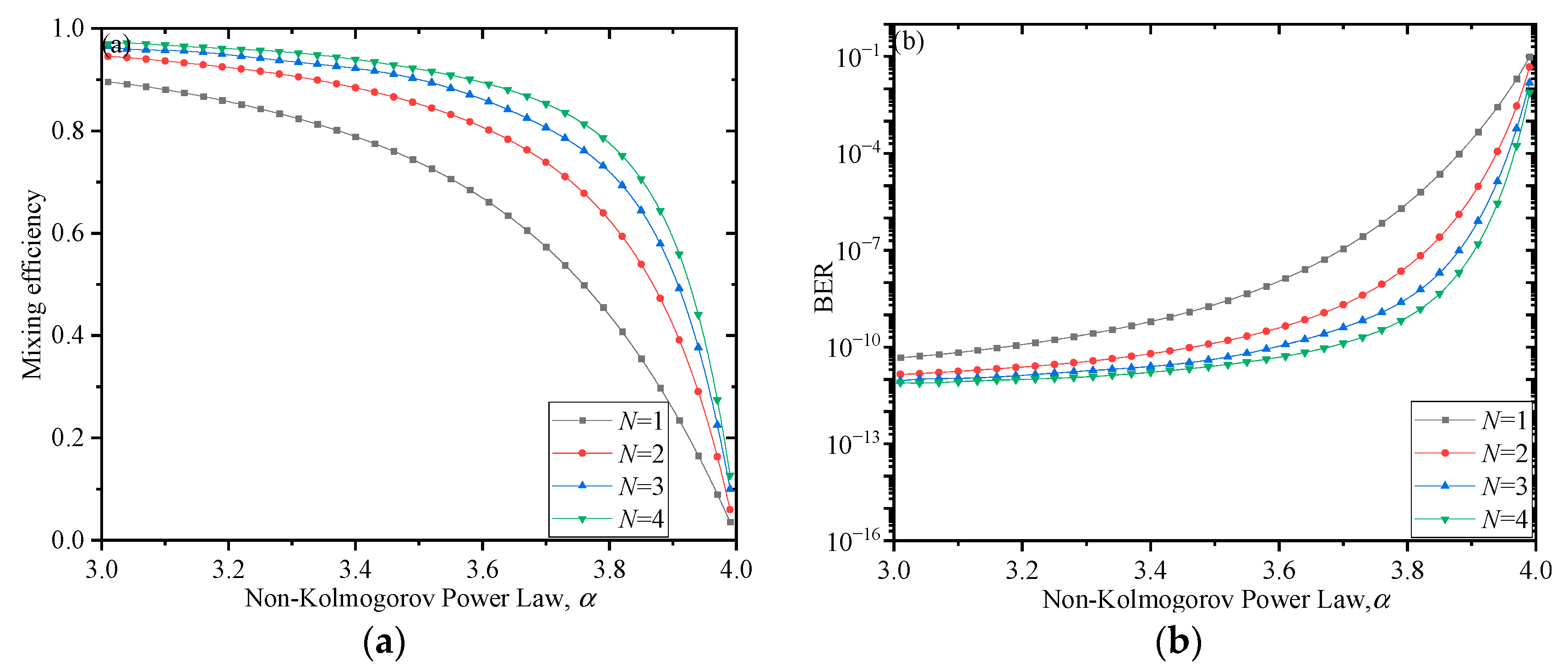
Figure 2a,b show the variation in the mixing efficiency and BER of the coherent detection system with the spectral power-law exponent
α under the conditions of the atmospheric turbulence slant propagation.
Figure 2a,b show that with the increase in the spectral power-law exponent
α, the mixing efficiency of the coherent detection system tends to decrease, and the BER tends to increase; the number of signal beams increases, the mixing efficiency of the coherent detection system at the receiving end increases, and the BER gradually decreases. We compare the single-beam and four-beam conditions at the transmitting end, and when the spectral power-law index
α is 3.9, the corresponding mixing efficiency of the single beam at the receiving end is 0.26, and the BER is lower than 10
−4; when the transmitting end has four beams, the receiving end’s mixing efficiency is 0.6, and the BER tends to be on the order of 10
−8. Among them, the mixing efficiency increased by 0.34, and the BER decreased proportionally. It can be concluded that as the number of signal beams transmitted by the transmitting end increases, when passing through the atmospheric turbulence slant propagation, the wavefront is superimposed, and it can partially compensate for the decrease in mixing efficiency and increase in BER of the coherent detection system at the receiving end as the spectral power-law index
α increases.
Under the condition that the spectral power-law exponent
α = 10/3, the other parameters are given in the numerical simulation in
Figure 2. In non-Kolmogorov turbulence, the phase of the signal light is distorted by the wavefront, when multi-beam transmission is used, according to Equation (3); when the zenith angle
ψ is in the range of 0–0.5 π, the mixing efficiency and BER of the coherent detection system change with the zenith angle during oblique transmission, as shown in
Figure 3.
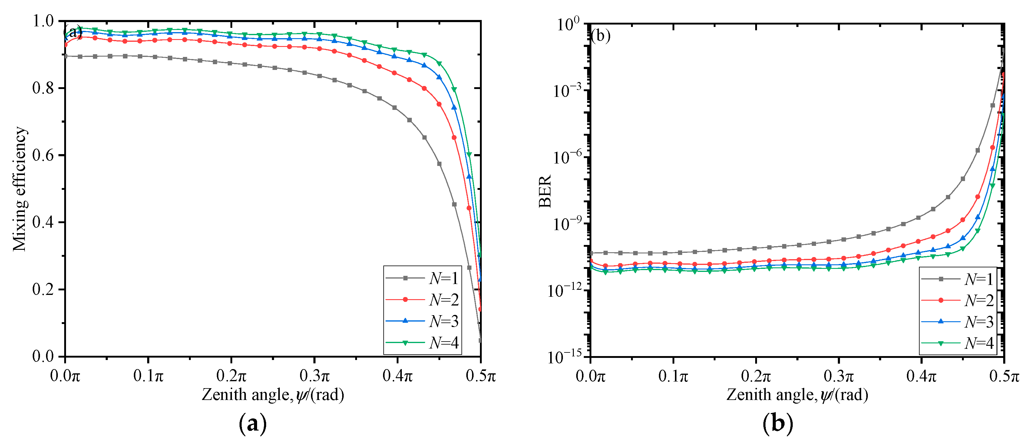
Figure 3a,b are the variation curves of the zenith angle
ψ versus the mixing efficiency and BER of the coherent detection system when different signal beams are transmitted at the transmitting end.
Figure 3a shows that in non-Kolmogorov turbulence, when the zenith angle
ψ is 0 (vertical transmission), the mixing efficiency is the largest, and then as the zenith angle
ψ increases, the mixing efficiency of the coherent detection system gradually decreases; as the zenith angle
ψ increases to 0.5 π (horizontal transmission), the mixing efficiency drops to a minimum. When a single beam is transmitted at the transmitting end, the zenith angle
ψ is 0, corresponding to a mixing efficiency of 0.89. When the zenith angle
ψ increases to 0.5 π, the mixing efficiency drops to 0.05.
Figure 3b shows that when the four-beam transmission is used at the transmitting end, as the zenith angle
ψ increases, the BER increases slowly, and when the zenith angle continues to increase to 0.5 π, the BER deteriorates to 10
−5. We find that as the number of signal beams transmitted by the transmitting end increases, when passing through the atmospheric turbulence slant propagation, the wavefront is superimposed, and it can partially compensate for the decrease in mixing efficiency and increase in BER of the coherent detection system at the receiving end as the zenith angle
ψ increases.
In the non-Kolmogorov turbulence slant propagation, under the conditions of the spectral power-law exponent
α = 10/3 and zenith angle
ψ = π/3, the rest of the parameters are set to the same simulation parameters as those in
Figure 2. When the transmission distance
L is changed, the mixing efficiency and BER at the receiving end calculated in Equations (22) and (23) can be obtained with simulation. The simulation results are shown in
Figure 4.
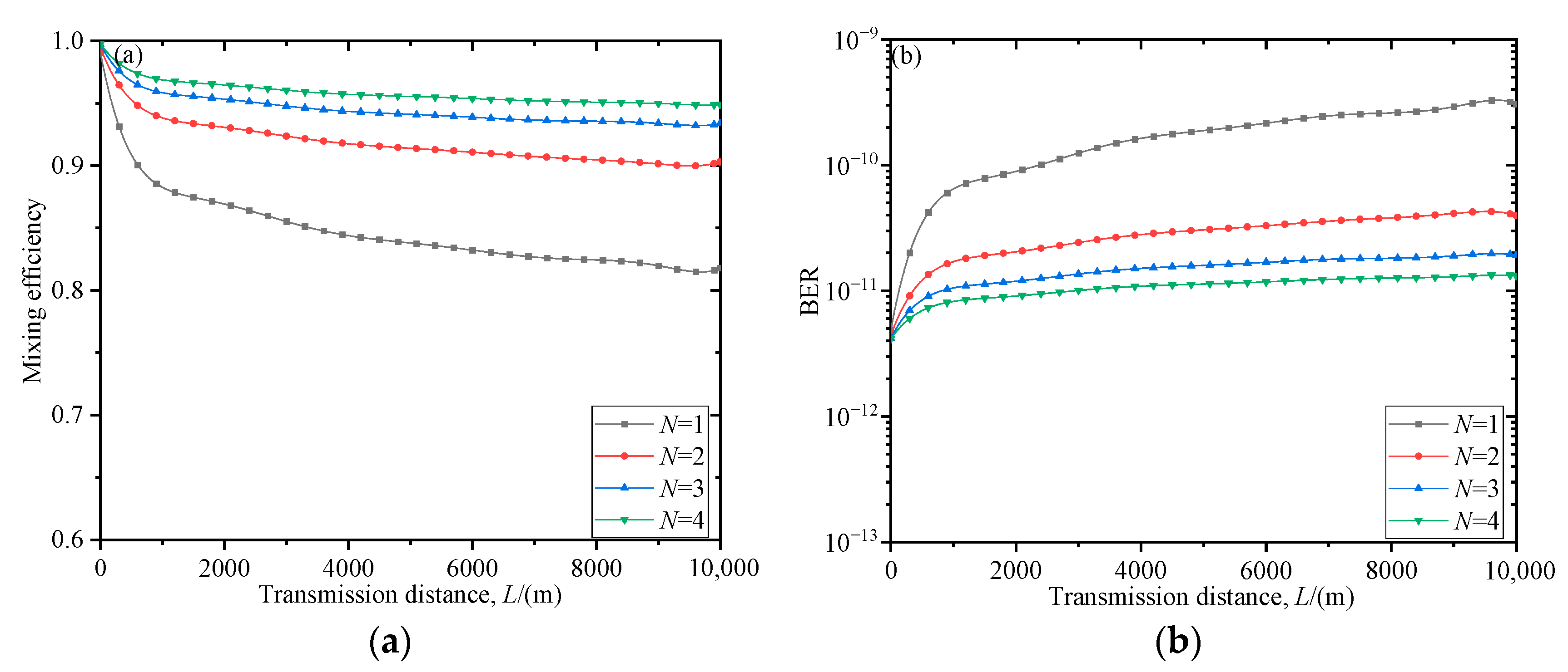
Figure 4a,b show the variation in the system’s mixing efficiency and BER with the transmission distance
L using the non-Kolmogorov turbulence slant propagation. It can be seen from
Figure 4a,b that as the transmission distance
L increases, the mixing efficiency of the coherent detection system decreases, and the BER increases. We compare the single-beam and four-beam conditions at the transmitting end. When the transmission distance
L is 10 km, the corresponding mixing efficiency of the single beam at the receiving end is 0.81, and the BER tends to be around 10
−9; when the transmitting end has four beams, the mixing efficiency of the receiving end is 0.94, and the BER tends to be around 10
−11. From the single beam to four beams, the mixing efficiency is increased by 0.13 and the BER is reduced by two orders of magnitude. It can be concluded that as the number of signal beams transmitted by the transmitting end increases, when passing through the atmospheric turbulence slant propagation, the wavefront is superimposed, and it can partially compensate for the decrease in mixing efficiency and increase in BER of the coherent detection system at the receiving end as the transmission distance
L increases.
In the non-Kolmogorov turbulence slant propagation, under the condition that the spectral power-law exponent
α = 10/3, the rest of the parameters are set to the same simulation parameters as those in
Figure 2. When the Fresnel zone (
λL)
1/2 changes, the mixing efficiency and BER at the receiving end calculated in Equations (22) and (23) can be obtained with simulation. The simulation results are shown in
Figure 5.
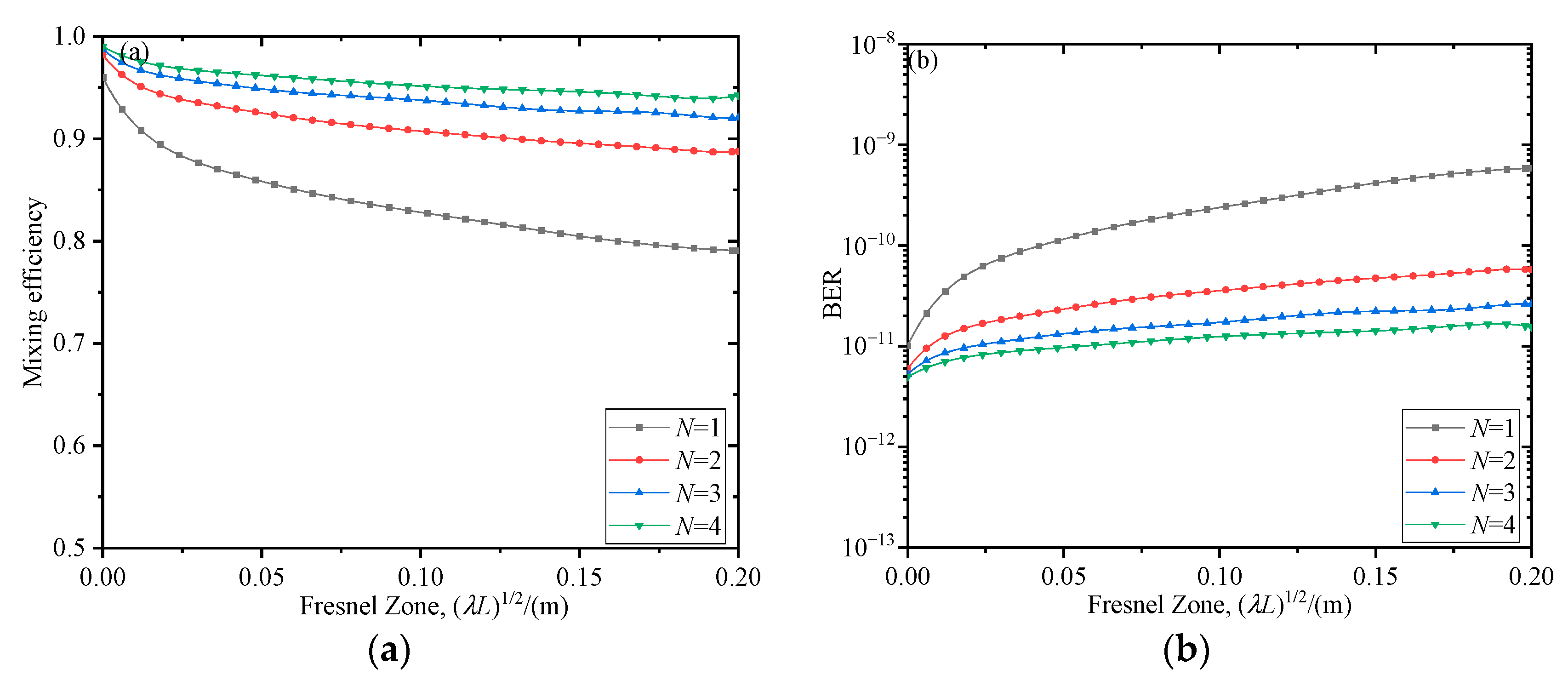
Figure 5a,b examine the relationship between the mixing efficiency and BER of the coherent detection system at the receiving end as a function of the Fresnel zone (
λL)
1/2 during non-Kolmogorov turbulence slant propagation. It can be seen that as the Fresnel zone (
λL)
1/2 increases, the mixing efficiency decreases gradually, and the BER increases gradually. We compared the single-beam and four-beam transmission conditions at the transmitting end in non-Kolmogorov atmospheric turbulence. When the Fresnel zone (
λL)
1/2 is 0.18 m, the mixing efficiency of the receiving end is maintained at 0.79 for a single beam, and the BER tends to be around 10
−9; when the transmitting end has four beams, the receiving end has a mixing efficiency of 0.94 and a BER of around 10
−11. From the single beam to four beams, the mixing efficiency is increased by 0.15, and the BER is reduced by two orders of magnitude. It can be concluded that as the number of signal beams transmitted by the transmitting end increases, when passing through the atmospheric turbulence slant path link, the wavefront is superimposed, and it can partially compensate for the decrease in mixing efficiency and increase in BER of the coherent detection system at the receiving end as the Fresnel zone (
λL)
1/2 increases.
In non-Kolmogorov turbulence conditions, the phase of the signal light is distorted by the wavefront with multi-beam transmission according to Equation (3). The values of the main parameters are set to be the same as those given in the numerical simulation in
Figure 2. Under different occlusion ratios, the mixing efficiency of the system and the corresponding BER vary with the pointing error attenuation variance as shown in
Figure 6.
Figure 6a,b show that as the pointing error attenuation variance increases, the mixing efficiency of the coherent detection system decreases, and the BER increases. For both mixing efficiency and BER, the pointing error attenuation variance is around 10
−12. When a single beam is transmitted, the mixing efficiency of the system decreases from 0.89 to 0.82 with the increase in the shading ratio. We compare the single-beam and two-beam situations at the transmitter, and when the occlusion ratio is the same, the mixing efficiency of the system is effectively improved and the BER is reduced. It can be concluded that as the number of signal beams transmitted by the transmitting end increases, when passing through the atmospheric turbulence slant path link, the wavefront is superimposed, and it can partially compensate for the decrease in mixing efficiency and increase in BER of the coherent detection system at the receiving end as the pointing error attenuation variance increases.
4. Experimental Research
To study the effect of multi-beam transmission at the transmitting end on the performance of the optical wireless coherent detection system in atmospheric turbulence, a system measurement experiment was first set up, as shown in
Figure 7. The beam output from the laser is divided into two beams using a 50:50 1 × 2 coupler, and then output using a collimator. One beam passes through the frosted glass to produce a constant wavefront distortion phase, and after being reflected by the mirror and the beam splitter, it finally passes through the 4F system to measure the wavefront phase. After the other beam is transmitted through the beam splitter, the beam is narrowed with the 4F system composed of lens 1 and lens 2, and finally, the wavefront sensor measures the wavefront phase.
In the experiment, the wavefront phases of each output and simultaneous output were measured. The laser wavelength is 650 nm, and the wavefront sensor model is Imagine Optic’s HASO4 First.
Figure 8 corresponds to the wavefront Zernike coefficient and wavefront phase measurement results collected from collimator 1 output, collimator 2 output, and collimator 1 and collimator 2 output, simultaneously.
Figure 8 shows that the wavefront phase of the composite beam is equal to the spatial accumulation of the wavefront phases of the independent beams, and the wavefront Zernike coefficient of the composite beam is equal to the numerical sum of the wavefront Zernike coefficients of the independent beams.
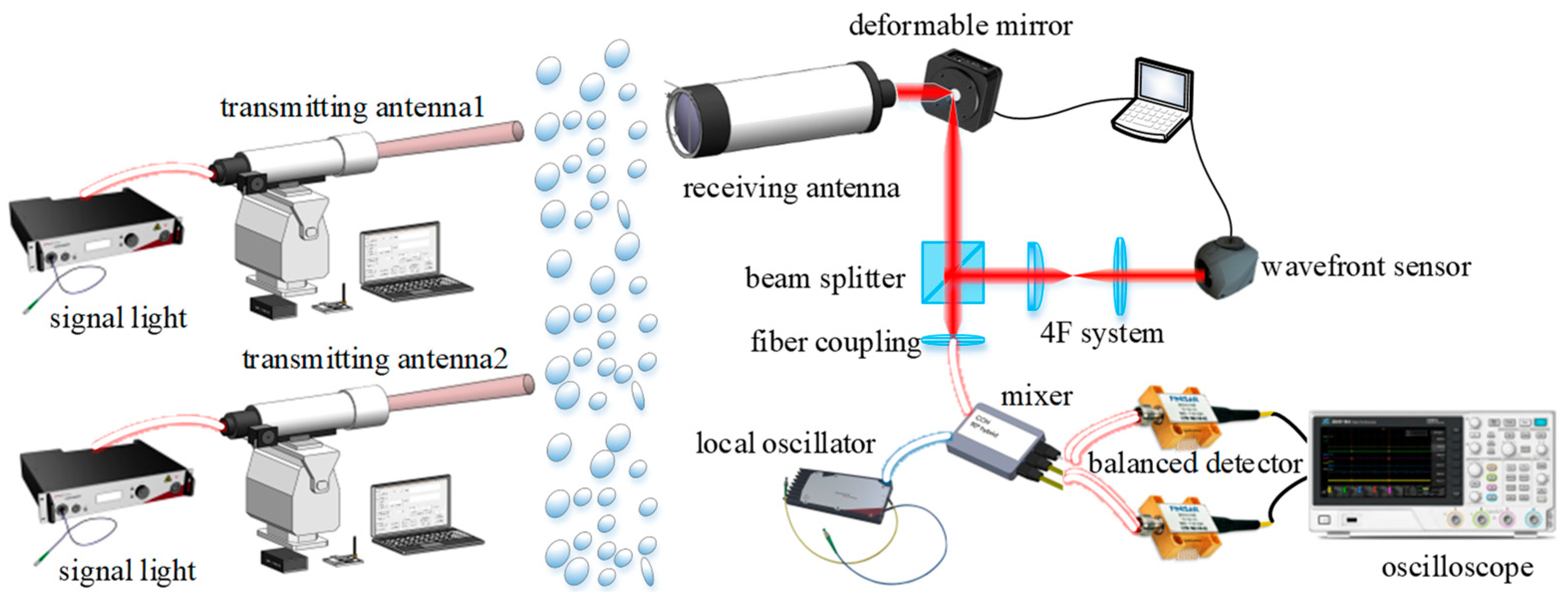
To further verify the correctness of the influence of multi-beam transmission on the performance of the receiving end system in the theoretical analysis, an optical wireless coherent communication system for multi-beam transmission is built. In the case of two beams at the transmitting end, the experimental principle is shown in
Figure 9. After the signal beam is transmitted to the receiving end through the receiving antenna, it is reflected by the piezoelectric deformable mirror and passes through the beam splitter in the parallel exit. When the light beam enters the wavefront correction system, it first narrows the beam through the 4F system to match the size of the photosensitive surface of the wavefront sensor, and then passes through the computer-controlled piezoelectric deformable mirror to perform closed-loop correction of the wavefront distortion. The corrected beam is transmitted into the coupling lens in the direction parallel to the optical axis, mixed with the local oscillator laser in the experimental control box, and then passed through the balanced detector, and the IF signal is viewed through the oscilloscope. For the setup: both the signal beam and the local oscillator beam are narrow-linewidth lasers from NKT Photonics, the wavefront sensor model is Imagine Optic’s HASO4 NIR, the piezoelectric deformable mirror model is Thorlabs’ FBH750-40, and the mixer model is Kylia’s COH24. The balanced detector’s model is BPDV2150R. The experimental link is from the sixth floor of Xi’an University of Technology to Kaisen Fujing Yayuan; the communication distance is 1.3 km, the weather environment is cloudy, and the north wind is level 2.
When the communication distance
L = 1.3 km, the receiving aperture
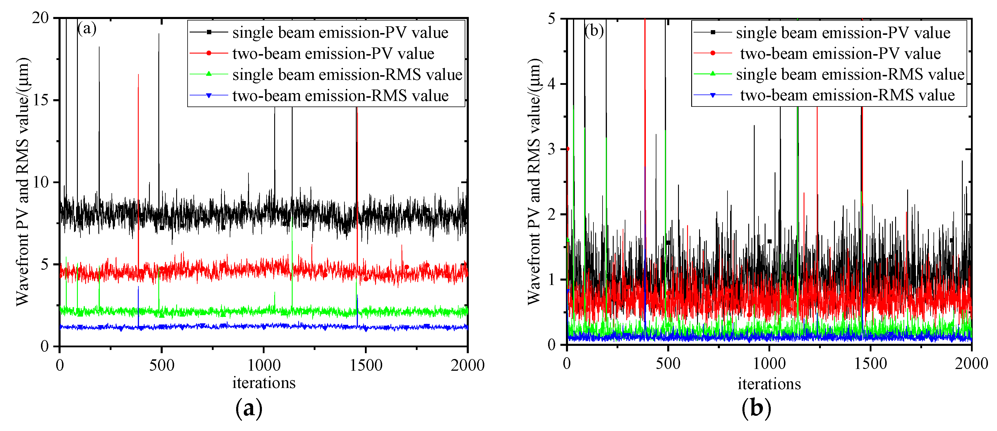
D = 200 mm, the signal optical power is about 1 mW, and the local oscillator optical power is about 10 mW. For single-beam and two-beam transmission, the peak-to-valley (PV) and root mean square (RMS) values of the wavefront before and after correction were measured, in that order, as shown in
Figure 10. The self-noise inside the wavefront sensor leads to partial synaptic data in the wavefront slope and wavefront phase measurements.
Figure 10 shows that when the wavefront is studied uncorrected, the mean values of the wavefront PV and RMS of the single-beam transmissions are 8.06 μm and 2.13 μm, respectively, and the variances are 1.59 μm
2 and 0.06 μm
2. The mean values of PV and RMS of the two-beam transmissions are 4.56 μm and 1.19 μm, respectively, and the variances are 0.06 μm
2 and 0.01 μm
2. These measurements further show that the wavefront smoothing effect and jitter suppression effect under multi-beam transmission are better than those under single-beam transmission, and the suppression effect is more obvious as the number of beams in transmissions increase; after wavefront correction using a 40-element piezoelectric deformable mirror, the mean values of wavefront PV and RMS are 1.15 μm and 0.22 μm, respectively, and the variances are 1.68 μm
2 and 0.05 μm
2 during single-beam transmission at the transmitting end, while the mean values of wavefront PV and RMS during transmission of the two beams are 0.73 μm and 0.19 μm, respectively, and the variances are 0.23μm
2 and 0.01 μm
2. It is concluded that after two beams are used for transmission, the corrected wavefront convergence degree at the receiving end is smoother.
When the experimental environment and experimental parameters are the same as those given in
Figure 10, the wavefront-corrected IF signals transmitted by a single beam and two beams are collected, and the amplitude changes of the obtained IF signals are shown in
Figure 11.
Figure 11 shows the waveform of the IF signal output from the detector after the wavefront correction is performed at the receiving end for single-beam transmission and two-beam transmission at the transmitting end. It can be seen that when a single beam of light is transmitted at the transmitting end, the transverse scanning speed is 5 ns/div, and the sinusoidal waveform of the IF signal obtained after correction is relatively irregular. When the transverse scanning speed is 4 μs/div, the amplitude fluctuation of the IF signal is more obvious; when the transverse scanning speed is 5 ns/div, after two beams of light are transmitted, the sinusoidal waveform of the IF signal is regular, and when the transverse scanning speed is 4 μs/div, the amplitude of the IF signal is relatively stable. Therefore, the gain brought by the multi-beam transmission can be directly reflected in the amplitude stability of the IF signal, which is beneficial for subsequent demodulation processing.
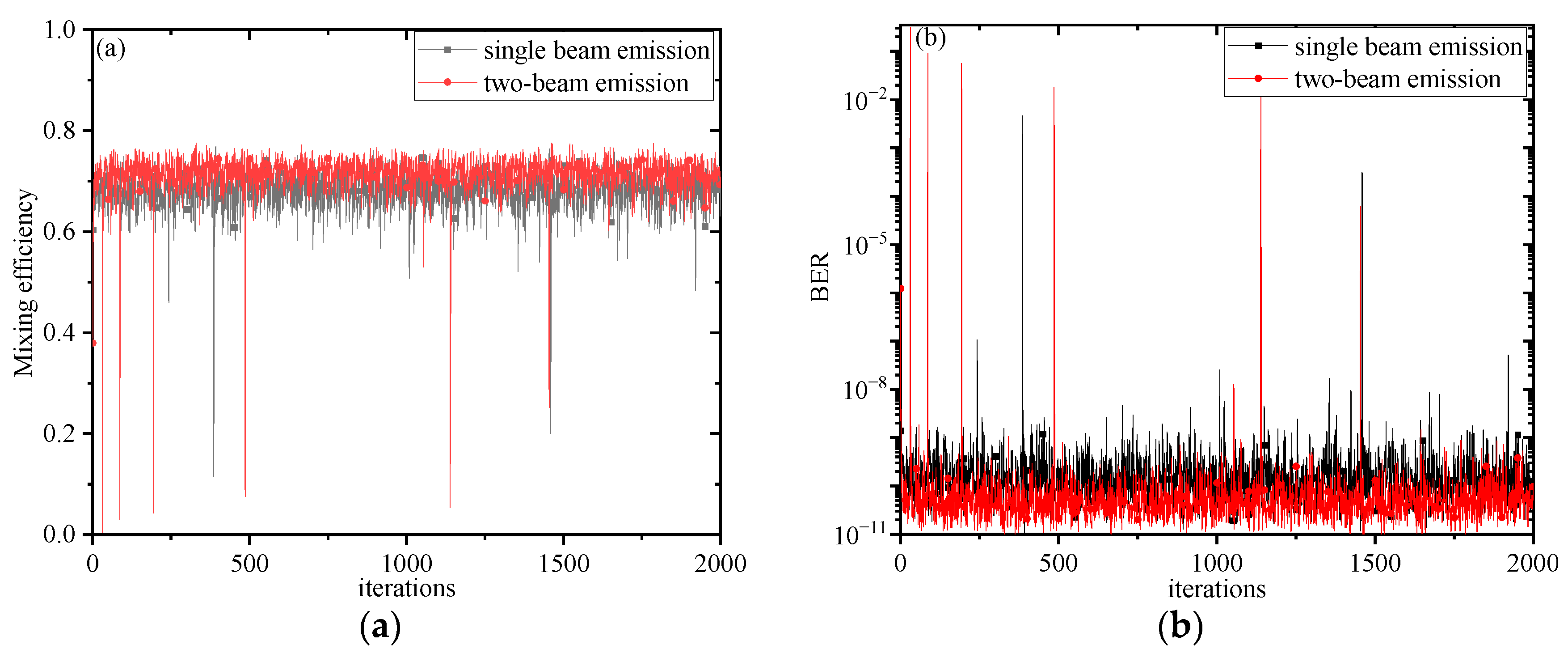
Using single-beam transmission and two-beam transmission, the mixing efficiency and BER curves obtained after wavefront correction at the receiving end are shown in
Figure 12.
Figure 12 shows that the advantages of two-beam transmission are more than single-beam transmission in terms of mixing efficiency and BER, and the fluctuation is smaller. The BER is stable around 10
−9 during single-beam transmission, but the BER is stable around 10
−10 during multi-beam transmission. It is further proved that multi-beam transmission has a greater gain in improving the optical wireless coherent detection system than single-beam transmission.
6. Conclusions
In this paper, under non-Kolmogorov turbulence conditions, a theoretical model of system mixing efficiency and BER is established for multi-beam slant transmission at the transmitter. Considering the transmission characteristics of signal beams, the effects of various factors on the mixing efficiency and BER of the system under different numbers of transmission beams in non-Kolmogorov turbulence are compared, and corresponding experimental verification is carried out. Numerical analysis results show that the mixing efficiency and BER of the system will be affected by the spectral power-law exponent α and the zenith angle ψ. When the spectral power-law exponent α increases gradually and different transmission beams are used for coherent detection, the mixing efficiency of the system decreases, and the BER increases accordingly. When the corresponding single beam at the transmitting end is increased to four beams, the spectral power-law index α is 3.9, and the corresponding mixing efficiency is increased by 0.34. When multiple beams are transmitted vertically, the system mixing efficiency is the highest. As the zenith angle ψ increases, the system mixing efficiency decreases, the BER increases, and the performance of the coherent detection system at the receiving end is seriously attenuated. Under the same conditions, as the transmission distance L increases, the mixing efficiency of the coherent detection system for multi-beam transmission at the transmitting end decreases gradually, and the BER increases gradually. When the single beam at the transmitting end is increased to four beams and the transmission distance L is 10 km, the corresponding mixing efficiency is increased by 0.13, and the BER is reduced by two orders of magnitude. When the Fresnel zone (λL)1/2 and pointing error attenuation variance increase, and different transmission beams are used for coherent detection, the mixing efficiency of the system decreases, and the BER increases accordingly. When the single beam at the transmitting end is increased to four beams, the Fresnel zone (λL)1/2 is 0.18 m, and the corresponding mixing efficiency is increased by 0.15. Combined with experimental verification, we found that wavefront distortion and wavefront jitter can be improved by the superposition of multi-beam transmission wavefronts, which effectively reduces the influence of atmospheric turbulence on beam transmission. With the increase in the transmission beam number, the mixing efficiency and BER of the receiving end system can be effectively improved.

