Article

Multi-Channel Long-Distance Audio Transmission System Using Power-over-Fiber Technology

1
School of Science, Hubei University of Technology, Wuhan 430068, China
2
Hubei Engineering Technology Research Center of Energy Photoelectric Device and System, Hubei University of Technology, Wuhan 430068, China
*
Authors to whom correspondence should be addressed.
Photonics 2023, 10(5), 521; https://doi.org/10.3390/photonics10050521
Submission received: 20 March 2023 / Revised: 9 April 2023 / Accepted: 23 April 2023 / Published: 1 May 2023

Abstract

:
To establish stable communication networks in harsh environments where power supply is difficult, such as coal mines and underwater, we propose an effective scheme for co-transmission of analog audio signals and energy. By leveraging the advantages of optical fibers, such as corrosion resistance and strong resistance to electromagnetic interference, the scheme uses a 1550 nm laser beam as the carrier for analog audio signal propagation, which is then converted to electrical energy through a custom InGaAs/InP photovoltaic power converter (PPC) for energy supply and information transfer without an external power supply after a 25 km fiber transmission. In the experiment, with 160 mW of optical power injection, the scheme not only provides 4 mW of electrical power, but also transmits an analog signal with an acoustic overload point (AOP) of 105 dBSPL and a signal-to-noise ratio (SNR) of 50 dB. In addition, the system employs wavelength division multiplexing (WDM) technology to transform from single-channel to multi-channel communication on a single independent fiber, enabling the arraying of receiving terminals. The passive arrayed terminals make the multi-channel long-distance audio transmission system using power-over-fiber (PoF) technology a superior choice for establishing a stable communication network in harsh environments.

1. Introduction

Power-over-fiber (PoF) is an attractive power supply technology with higher insulation characteristics and lower transmission losses than traditional cable-based power supply [1]. In particular, in some special applications, such as underground mines due to the presence of flammable and explosive gases, it will be safer to use optical fibers with strong anti-electromagnetic interference capabilities for power supply, and communication lines based on PoF will also be more stable [2]. Based on the existing optical fiber architecture, powering a communication system through PoF links does not require the installation of additional power supply facilities or power lines, which makes the installation of remote communication equipment easier and more adaptable to a wider range of installation environments [3].
PoF is a considerably mature technology, and its research and development have been conducted since the late 1970s [4,5]. A summary of the main achievements in PoF applied to radio-over-fiber (RoF) for different types of fibers and commercial products is reported in [6]. Higher PoF power levels are fed using multimode fibers (MMFs) and high-power lasers (HPLs) at around 808 nm, and one of the latest experiments achieved the goal of providing 6.2 W of electrical power over a 1.5 m MMF [7]. The Motoharu team in Japan has long worked on the design and improvement of high-power PoF systems. They presented a PoF technique using double-clad fibers (DCFs) [2,8,9,10,11,12]. Recently, DCFs have been able to feed up to 150 W of optical power [11] in a 1 km-long link with a 4.84% optical-to-electrical (O/E) power transmission efficiency, from HPL optical power to photovoltaic (PV) converter electrical power. For the schemes based on multicore fiber (MCF), the power light and signal light at the same wavelength of 1549.3 nm are propagated with different dedicated cores, whereas the total optical power arising in the seven-core fiber is generally smaller than 1 W, due to crosstalk and nonlinearity [13,14].
All the above schemes are used to achieve the common transmission of energy and information through DCF, MCF, and MMF, with emphasis on further improving the energy or transmission rate of the system transmission. However, the link length also needs to be considered in practical applications. Usually, the depth of a mine will reach tens of kilometers or even longer distances. In long-distance transmission scenarios, the losses in the fiber gradually become more significant than those caused by photoelectric conversion and device connections as the transmission distance increases. As a result, it is crucial to pay special attention to the losses incurred due to optical fiber transmission. To address this issue, single-mode fiber (SMF) with low mode dispersion and signal crosstalk effects becomes the preferred choice for long-distance transmission application scenarios. Several PoF systems using SMFs have been reported thus far [15,16,17,18,19], and one of them experimentally demonstrated a PoF system based on 14.43 km of an SMF fed by 2.24 W, yielding 226 mW of electrical power at the low-power remote radio heads (RRHs) for control, battery charge, load operation, and communication purposes [17]. To improve the power supply capability of PoF technology, the development of photovoltaic power converters (PPCs) plays a crucial role. Among the continuous development of PPCs, the low transmission loss of long-wavelength PPCs in silica fibers has attracted much attention [20]. For example, An-Cheng Wang et al. prepared an eight-junction In0.53Ga0.47As laser power converter for 1520 nm laser energy conversion, with a maximum conversion efficiency of 36.9% at room temperature [21]. In addition, Simon Fafard et al. developed a 10-junction InP-based PPC that can produce electrical output voltages greater than 4~5 V with 7 W of 1466 nm laser irradiation by connecting more sub-cells in vertical series [22]. These PPC advancements provide higher energy transfer efficiency for PoF technology, giving it a greater potential to deliver more power over longer distances.
In this paper, we proposed a multichannel long-distance audio transmission system based on PoF and wavelength division multiplexing (WDM). To enhance the electric power driving the electro-acoustic converter, we employed a custom InGaAs/InP PPC capable of directly converting optical power to electrical power. This PPC can receive up to 400 mW of optical power input and boasts a photoelectric conversion efficiency of over 35%. The system achieved the co-transmission of 160 mW of optical power and optically carried analog audio signals over a 25 km SMF. The acoustic overload point (AOP) of the transmitted audio signal is 105 dBSPL, and the signal-to-noise ratio (SNR) is 50 dB. Since the signals transmitted by the system are analog audio signals, no specialized demodulation equipment is needed at the receiving end. The electrical power obtained from the PPC conversion is sufficient to drive the electro-acoustic converter for outputting audio signals without requiring an additional power supply. This feature provides the system with significant advantages in establishing a stable communication network in challenging scenarios, such as coal mines and underwater environments, where power supply is difficult. Moreover, by employing WDM technology, long-distance communication between multiple users is realized, adding an audio-locating function to the system. In the event of an earthquake or mining disaster, this communication system can quickly pinpoint the disaster location, saving valuable time for rescue efforts.

2. Experimental Setup for the Passive Audio Transmission System

Figure 1 shows the experimental setup for downlink analog audio signal transmission using a 25 km SMF. This multichannel audio transmission system consists mainly of a transmitter, a receiver, and the SMF, connecting two stations.
Considering that the lowest transmission loss window is located near the 1550 nm band, the transmitter adopts a distributed feedback laser diode (DFB-LD) with a central wavelength of 1549.74 nm. The DFB-LD has excellent single-frequency stability and temperature characteristics, which enable it to suppress laser mode jumps over a wide range of operational temperatures and currents, delivering a constant output mode that meets the requirements of SMF for light sources. The transmitter of the system mainly implements the function of modulating the signal. In optical communication links, there are two main methods to modulate the electrical signal on the optical carrier: external modulation and direct modulation [23]. The external modulation method passes the electronic signal to the optical domain with the use of a separate modulator, such as the LiNbO3 modulator, electric absorption modulator (EAM), etc., with high costs and optical insertion loss. In the system of this paper, the direct modulation method was chosen. This method modulates the laser current with the analog electronic signal, enabling the analog electronic signal to be placed on an optical carrier. The main advantage of this approach is the lower cost level and the reduced system complexity, with respect to the external modulation case. At the transmitter side, the audio signal is first converted into a weak alternating current (AC) signal through a microphone, which has a peak-to-peak value of only 10 mV and is amplified 30 times by an in-phase amplifier. The amplified electrical signal passes through a band-pass filter (20 Hz to 8 kHz) and is then loaded on the drive current of the DFB-LD at 200 mA to achieve direct modulation of the analog electronic signal, and the modulation depth is 78.9%. With a DFB-LD emitting 40 mW (16 dBm) of power light, the total power output of the four channels is 160 mW. The four modulated power light beams are combined through a C-band dense wavelength division multiplexer (DWDM) with a 100 GHz spacing and transmitted into the 25 km SMF. The SMF is a commercially available optical fiber with an SM core diameter of 9 µm, suitable for transmitting the power and audio signals with minimal loss.
After the 25 km SMF transmission, the power light is separated by the DWDM and transmitted to multiple users according to the wavelength. The receiver circuit comprises a photovoltaic power converter (PPC) and an AC/DC separation circuit. The PPC is responsible for converting optical signals into electrical signals. The separation circuit consists of two parallel-connected branches. In the first branch, an inductor and a resistor are connected in series to extract the DC portion of the signal, which subsequently powers the electro-acoustic converter. In the second branch, a capacitor and a resistor are employed to separate the AC portion of the signal, which is then further transformed into an audio signal by the electro-acoustic converter. The system utilizes a low-impedance, high-sensitivity dynamic earphone as the electro-acoustic converter, which necessitates a relatively low driving power. This characteristic renders it ideally suited for low-power, long-distance applications, while its high sensitivity enables the amplification of weak signals.
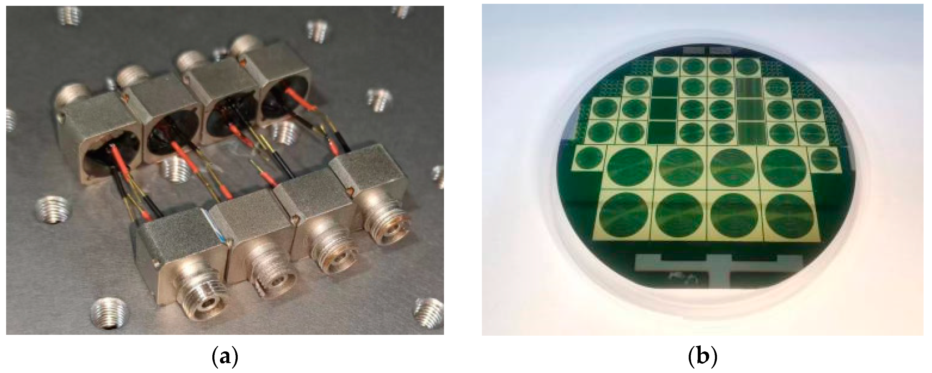
In actual coal mine applications, energy and signal loss after long-distance transmission is a very obvious problem due to the lack of introduction of optical amplification technology, making the PPC used in long-distance PoF technology have some special requirements that are more suitable for our scenario applications. Since the lowest transmission loss window of the single-mode silica fiber is located near the 1550 nm band, the PPC suitable for the long-distance audio transmission system in this paper is made of the best material suitable for absorption of this C-band wavelength. The PPC with the TO coaxial package is shown in Figure 2a.
To overcome the drawback of low voltages (≤1 V) for a single-junction PPC, we fabricated a monochromatic PPC containing six sub-cells using InGaAs/InP materials to boost their output voltage and raise the output impedance, meeting the requirements of the electronic devices, and the chip of the cell is shown in Figure 2b. These sub-cells were connected in series by InP/InP tunneling connections. Each sub-cell consisted of an N-type window (doping concentration of 6 × 10¹⁸/cm−3), an N-type emitter layer (doping concentration of 1 × 10¹⁸/cm−3), a P-type base layer (doping concentration of 5 × 10¹⁷/cm−3), and a P-type back-side field (BSF) layer (doping concentration of 2.5 × 10¹⁸/cm−3). The lengths of each sub-cell were 147 nm, 180 nm, 210 nm, 327 nm, 559 nm, and 2555 nm, respectively. N-type-doped Si or P-type-doped Zn were used for all the layers, except the InP/InP tunnel junction layer. For better performance of the PPC, a heavily doped 1.5 µm-thick window layer as a top lateral current layer was necessary, and it was grown on the top cell. Finally, a 300 nm-thick N-type cap layer was grown on the window layer as an ohmic contact to minimize the contact resistance. The low contact resistivity front grid was 6 µm-wide and 5 µm-thick. The thickness of this PPC chip was 150 µm, and the optimal absorption wavelength was around 1520~1530 nm. The specific characteristics of the PPC are shown in Figure 3.
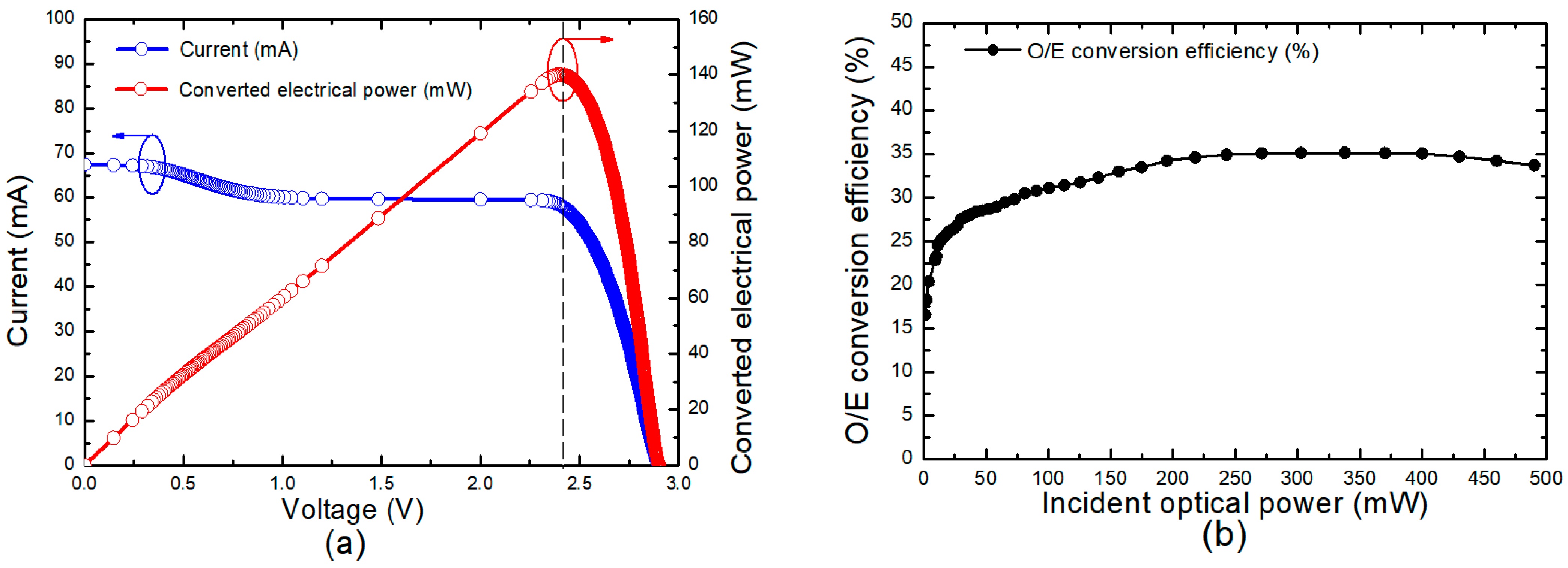
In order to test the maximum conversion efficiency of the PPC, a 1510 nm butterfly multimode PUMP laser (FOL1437) was used as the light source to provide sufficient incident light to the prepared 6-junction PPC for testing. Figure 3a shows its P-V and I-V characteristic curves at an input optical power of 400 mW. As the voltage for an electric load was increased, the converted electric power was linearly increased. The maximum electric power of 140.17 mW was obtained at approximately 2.4 V, and the voltage was called the maximum power point (MPP), as shown by the dashed line in Figure 3a. After that, the power was decreased as the voltage was increased. The open-circuit voltage corresponding to PPC was 2.93 V, and the short-circuit current was 67.4 mA. It is worth noting that the optimal operating wavelength for this PPC lies within the range of 1520 to 1530 nm. Consequently, the I-V curve exhibited slight distortion, attributable to a certain degree of mismatch between the incident light wavelength and the PPC. To better understand the performance of the PPC, we further tested the conversion efficiency variation of the PPC at different incident light powers, as shown in Figure 3b. When the incident light power increased from 1 mW to 480 mW, the conversion efficiency of the PPC showed a trend of first increasing and then decreasing. This phenomenon is mainly because high-power light irradiation caused the temperature of the PPC to rise, and the photogenerated current and reverse saturation current of the PPC showed nonlinear changes with the temperature. The conversion efficiency of the PPC can reach a maximum of 35.1% under a 400 mW light intensity incidence. Therefore, we can use the self-powered characteristic of the PPC and the third window characteristic of low-loss optical fiber transmission to achieve passive transmission of audio signals.

3. Transmission Performance Measurement

The purpose of building the long-distance audio transmission system based on POF was to achieve a stable power supply through a single optical fiber, while still transmitting audio signals with high quality. In order to comprehensively evaluate the performance of the audio transmission system, we tested and evaluated the system from two aspects: power transmission performance and audio transmission effect.

3.1. Power Transmission Performance

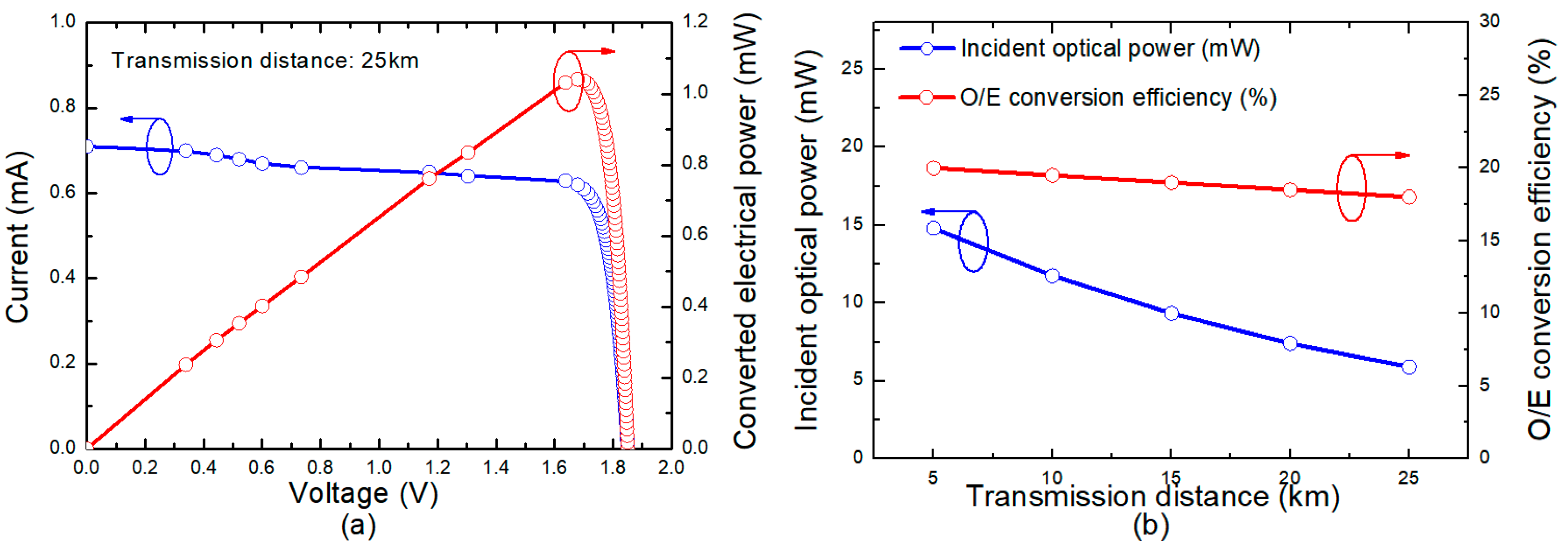
The optical power transmitted by the PoF link is converted into electrical power at the PPC, so the conversion efficiency of the PPC is an important factor in determining the total power transmission efficiency (PDE) of the PoF transmission. To test the output electrical power condition of the PPC, we used a parameter analyzer (Keithley 4200A-SCS) to measure the output of the PPC after a 25 km SMF transmission. Due to the long transmission distance, the 40 mW (16 dBm) laser emitted from each channel was reduced to only 6 mW (7.7 dBm) received by the PPC. The 8.3 dB power loss includes a total of 3.3 dB from transmission, reflection, and connection losses on the two DWDMs, as well as a 5 dB transmission loss in the fiber. Due to the weak incident optical power, the PPC was not operating at its optimal conversion efficiency state, as shown in Figure 3a. Nonetheless, the conversion efficiency of the PPC in this low-light condition still surpassed that of most conventional PPCs, reaching approximately 18%. The P-V and I-V characteristic curves of the PPC are shown in Figure 4a. When the MPP was 1.68 V, the maximum output power was 1 mW.
In long-distance transmission scenarios, as the transmission distance increases, the loss in the fiber will gradually become dominant over the losses due to photoelectric conversion and device connections. In this situation, special attention should be paid to the losses caused by fiber transmission. Therefore, we measured the incident PPC optical power and the conversion efficiency of the PPC at different transmission distances, from 5 km to 25 km. The results are shown in Figure 4b. The optical power incident on the PPC decreased almost linearly with the increasing distance, and the O/E conversion efficiency also decreased. Specifically, when the transmission distance was 25 km, the O/E conversion efficiency of the PPC decreased to 18%, and the transmitted electrical power of the system was 4 mW. This phenomenon is due to the increasing absorption and scattering losses in the optical fiber, which increased with distance and resulted in a subsequent decrease in the strength of the optical signal. This shows that if there are measures to suppress the attenuation in the fiber, the transmission power and conversion efficiency can be further improved.

3.2. Transmission Performance of Analog Audio Signals

To evaluate the quality of the audio signal transmitted through the system, we measured the total harmonic distortion (THD), AOP, and SNR characteristics of the analog audio signal output at the headphones. The acoustic test platform for this experiment is shown in Figure 5. The audio system (GENELEC 8040B) sent out a sine wave with a frequency of 1 kHz and a sound pressure of 60 dBSPL~120 dBSPL, which was used as the analog signal input for the whole system. After long-distance SMF transmission, the output audio in the earphones was transmitted to a professional audio precision analyzer (ABTEC A2) to test its THD, AOP, and SNR. In the experiment, the impedance of the earphones was 150 ohms, and the sensitivity was 111 dB/mW. To prevent the interference of external environmental sound, the entire test experiment was carried out in a low-noise anechoic chamber with a cutoff frequency of 125 Hz and a background noise level below 15 dB(A). This type of soundproof chamber has excellent acoustic isolation properties, which effectively reduces the interference of external noise and provides a stable testing environment for the audio transmission system.
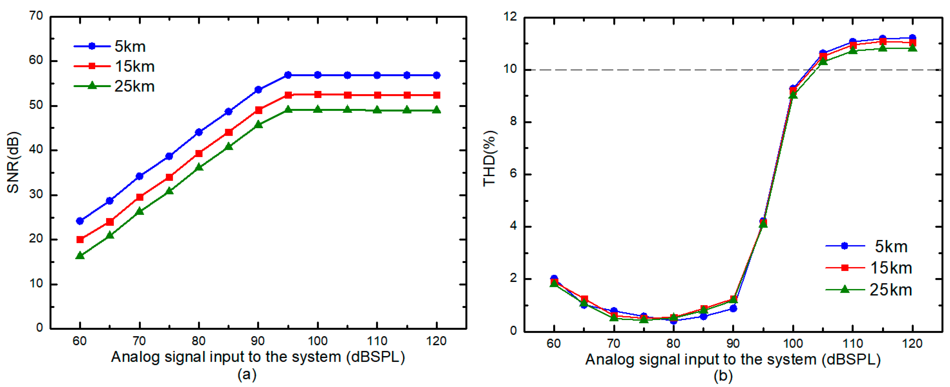
Due to the influence of various physical phenomena, nonlinear distortion will appear in the optical fiber transmission process. The degree of distortion received at the output depends on a variety of factors, including the characteristics of the optical fiber, its length, and the input power level of the audio signal. Therefore, this experiment measured the THD and SNR of the output audio signal at different transmission distances and different input sound pressures to evaluate the transmission effectiveness. With a fixed transmission distance and input frequency, the noise power level in the system remained stable. As shown in Figure 6a, when the input sound pressure was low, the signal strength was weak, and the noise was relatively large, resulting in a low SNR. As the input sound pressure increased, the signal strength also increased, leading to a linear increase in the measured SNR. However, when the input sound pressure reached 95 dBSPL, the output optical power of the DFB-LD saturated, at which point further increases in the input current would not significantly increase the output power, and the SNR would also tend to be stable. The SNR reached a maximum of 56.8 dB when the transmission distance was 5 km. As the transmission distance became longer, the SNR decreased, mainly due to the increased attenuation during fiber transmission, resulting in a weakened optical power. In addition, stray light and photon scattering in the fiber also introduced noise, further reducing the SNR. When the transmission distance reached 25 km, the SNR dropped to 50 dB.
The THD is a measure of the degree of harmonic distortion of the transmitted signal compared to the original signal. The smaller the THD is, the lower the distortion rate, and the better the signal transmission performance of the entire system. As shown in Figure 6b, when the input sound pressure was between 60 dBSPL and 95 dBSPL, the THD value of the output analog audio was almost always maintained below 2%, indicating a very low level of distortion. Nevertheless, as the input sound pressure was gradually raised, both the signal strength and the nonlinear effects in the optical fiber also increased. Consequently, the proportion of harmonic components in the audio signal gradually increased, causing an increase in the THD value. The AOP corresponds to the input sound pressure when the THD reaches 10%. As the transmission distance increased to 5 km, 15 km, and 25 km, the corresponding AOPs were measured to be 103.3 dBSPL, 103.5 dBSPL, and 105 dBSPL, respectively. The high AOP values are indicative of the larger dynamic range and strong anti-interference capability of the system. These results highlight that even under long-distance transmission of 25 km, the system exhibited an excellent signal transmission performance.

4. Discussion

To analyze the performance of the system, every single channel was characterized both individually and as a complete system. In this paper, to reduce the transmission loss of power light in an optical fiber, we used C-band power light and an SMF. In addition to the loss resulting from device connection and coupling, the nonlinear optical effect of light in the fiber also contributed to the loss. This is because the laser outputs 40 mW (16 dBm) of optical power, which surpasses the threshold for Brillouin scattering (SBS) in the single-mode fiber [24]. As the transmission distance increased, the loss caused by this effect also increased. The specific transmission loss is shown in Table 1. As the transmission distance increased, the transmission loss increased from 4.3 dB at 5 km to 8.3 dB at 25 km. For low-impedance, high-sensitivity headphones, 1 mW of power is sufficient to drive them. Combined with the conversion efficiency of the PPC of 18% (shown in Section 3), when the output power of the LD was 40 mW, it could output 1.0 mW of electrical power after the 25 km SMF transmission, which is sufficient to drive the headphones. Meanwhile, the audio signal transmitted by the whole system had a high AOP value of 105 dBSPL, which indicates that the system can transmit audio signals with high quality while supplying power.
The total transmitted power of the 25 km, four-channel audio transmission system implemented in this experiment was 4.0 mW. In addition to powering the headphones, this power level can drive different low-power electronic components (amplifiers, photodiodes, transmitters, etc.) to achieve different functions. This is an effective way to power long-range sensor networks in Internet of Things (IoT) applications. It is worth noting that if the output power of the laser could be further increased or attenuation in the fiber could be suppressed, then driving cameras, remote antenna units, and other devices for high-power applications will also be possible. By combining POF technology with WDM technology, it becomes possible to power multiple terminals while simultaneously enabling communication, thus enhancing both channel utilization and transmission capacity. This represents one of the possible directions for the future development of this technology. With the continuous development of IoT and intelligent technology, long-distance multi-channel transmission systems will gain more attention and play a role in more applications.

5. Conclusions

Focusing on a long-distance, low-power communication system, this paper successfully demonstrated the simultaneous transmission of audio signals and power over a 25 km SMF. To enhance the electrical power driving the electro-acoustic converter at the communication terminal, a customized InGaAs/InP PPC was employed to convert optical energy into electrical energy. This PPC was designed with six sub-cells connected in series through InP/InP tunneling, resulting in a higher conversion efficiency and output power for the C-band laser compared to the conventional single-junction PPC. With an optical power injection of 400 mW, the PPC achieved a conversion efficiency of up to 35%. Notably, this receiver has a simple structure and requires no additional power supply, making the system node passive and providing an effective mobile communication solution for harsh environments, such as mines or underwater, where the power supply is difficult to obtain. Furthermore, the analog audio signal transmitted by the system was subjected to various acoustic tests, which showed an AOP of 105 dBSPL and a SNR of 50 dB, demonstrating the high transmission performance and reliability of the system. With the addition of WDM technology, the system can transmit multiple optical powers on the same fiber, improving channel utilization and transmission capacity, which leads to new possibilities for practical applications.

Author Contributions

Conceptualization, C.G. (Can Guo) and C.G. (Chenggang Guan); methodology, C.G. (Can Guo) and C.G. (Chenggang Guan); software, C.G. (Can Guo); validation, C.G. (Can Guo); formal analysis, S.C. and H.C.; investigation, C.G. (Can Guo); resources, C.G. (Chenggang Guan) and H.L.; data curation, C.G. (Can Guo); writing—original draft preparation, C.G. (Can Guo); writing—review and editing, H.L.; supervision, C.G. (Chenggang Guan) and H.L.; funding acquisition, H.L. All authors have read and agreed to the published version of the manuscript.

Funding

This research was funded by the project of outstanding young and middle-aged science and technology innovation teams of colleges and universities in Hubei Province under Grant (No. T201907) and the International Science and Technology Cooperation Key Research and Development Program of Science and Technology Agency in Hubei Province (No. 2021EHB018).

Institutional Review Board Statement

Not applicable.

Informed Consent Statement

Not applicable.

Data Availability Statement

Not applicable.

Conflicts of Interest

The authors declare no conflict of interest.

References

  1. Matsuura, M. Recent Advancement in Power-over-Fiber Technologies. Photonics 2021, 8, 335. [Google Scholar] [CrossRef]
  2. Matsuura, M.; Sato, J. Bidirectional Radio-Over-Fibre Systems Using Double-Clad Fibre for Optically Powered Remote Antenna Units. IEEE Photonics J. 2015, 7, 1669. [Google Scholar] [CrossRef]
  3. Kuboki, H.; Matsuura, M. Optically powered radio-over-fibre system based on center- and offset-launching techniques using a conventional multimode fibre. Opt. Lett. 2018, 43, 1067. [Google Scholar] [CrossRef]
  4. DeLoach, B.C.; Miller, R.C.; Kaufman, S. Sound Alerter Powered Over an Optical Fibre. Bell Syst. Tech. J. 1978, 57, 3309–3316. [Google Scholar] [CrossRef]
  5. Miller, R.C.; Lawry, R.B. Optically Powered Speech Communication Over a Fibre Lightguide. Bell Syst. Tech. J. 1979, 58, 1735–1741. [Google Scholar] [CrossRef]
  6. Matsuura, M. Power-Over-Fibre Using Double-Clad Fibre. J. Light. Technol. 2022, 40, 3187–3196. [Google Scholar] [CrossRef]
  7. Helmers, H.; Armbruster, C.; von Ravenstein, M.; Derix, D.; Schoner, C. 6-W Optical Power Link With Integrated Optical Data Transmission. IEEE Trans. Power Electron. 2020, 35, 7904–7909. [Google Scholar] [CrossRef]
  8. Sato, J.; Matsuura, M. Radio-over-Fibre Transmission With Optical Power Supply Using a Double-Clad Fibre. In Proceedings of the 2013 18th OptoElectronics and Communications Conference Held Jointly with 2013 International Conference on Photonics in Switching (OSA, 2013), Kyoto, Japan, 30 June–4 July 2013; p. TuPO_8. [Google Scholar]
  9. Matsuura, M.; Sato, J. Power-over-fibre using double-clad fibre for radio-over-fibre systems. In Proceedings of the 2014 19th European Conference on Networks and Optical Communications—(NOC) (IEEE, 2014), Milan, Italy, 4–6 June 2014; pp. 126–131. [Google Scholar]
  10. Matsuura, M.; Furugori, H.; Sato, J. 60 W power-over-fibre feed using double-clad fibre for radio-over-fibre systems with optically powered remote antenna units. Opt. Lett. 2015, 40, 5598. [Google Scholar] [CrossRef]
  11. Matsuura, M.; Tajima, N.; Nomoto, H.; Kamiyama, D. 150-W Power-Over-Fibre Using Double-Clad Fibre. J. Light. Technol. 2020, 38, 401–408. [Google Scholar] [CrossRef]
  12. Matsuura, M.; Nomoto, H.; Mamiya, H.; Higuchi, T.; Masson, D.; Fafard, S. Over 40-W Electric Power and Optical Data Transmission Using an Optical Fibre. IEEE Trans. Power Electron. 2021, 36, 4532–4539. [Google Scholar] [CrossRef]
  13. Sakano, T.; Fadlullah, Z.M.; Kato, N.; Takahara, A.; Kumagai, T.; Kasahara, H.; Kurihara, S. Disaster-resilient networking: A new vision based on movable and deployable resource units. IEEE Netw. 2013, 27, 40. [Google Scholar] [CrossRef]
  14. Wu, J.J.; Zhang, Y.J.; Zukerman, M.; Yung, E.K.-N. Energy-efficient base-stations sleep-mode techniques in green cellular networks: A survey. IEEE Commun. Surv. Tutor. 2015, 17, 803. [Google Scholar] [CrossRef]
  15. Al-Zubaidi, F.M.A.; Lopez-Cardona, J.D.; Montero, D.S.; Vazquez, C. Optically Powered Radio-over-Fibre Systems in Support of 5G Cellular Networks and IoT. J. Light. Technol. 2021, 39, 4262–4269. [Google Scholar] [CrossRef]
  16. Diouf, C.; Quintard, V.; Ghisa, L.; Guegan, M.; Perennou, A.; Gautier, L.; Tardivel, M.; Barbot, S.; Dutreuil, V.; Colas, F. Design, Characterization, and Test of a Versatile Single-Mode Power-Over-Fibre and Communication System for Seafloor Observatories. IEEE J. Ocean. Eng. 2020, 45, 656–664. [Google Scholar] [CrossRef]
  17. Lopez-Cardona, J.D.; Altuna, R.; Montero, D.S.; Vazquez, C. Power Over Fibre in C-RAN with Low Power Sleep Mode Remote Nodes Using SMF. J. Light. Technol. 2021, 39, 4951–4957. [Google Scholar] [CrossRef]
  18. Wang, S.; Yang, H.; Qin, Y.; Peng, D.; Fu, S. Power-over-Fibre in Support of 5G NR Fronthaul: Space Division Multiplexing versus Wavelength Division Multiplexing. J. Light. Technol. 2022, 40, 4169–4177. [Google Scholar] [CrossRef]
  19. Yang, H.; Peng, D.; Qin, Y.; Li, J.; Xiang, M.; Xu, O.; Fu, S. 10-W power light co-transmission with optically carried 5G NR signal over standard single-mode fibre. Opt. Lett. 2021, 46, 5116. [Google Scholar] [CrossRef]
  20. Wang, A.-C.; Sun, Y.-R.; Yu, S.-Z.; Yin, J.-J.; Zhang, W.; Wang, J.-S.; Fu, Q.-X.; Dong, J.-R. A method to analyze current mismatch in a multijunction laser power converter based on I–V measurements. Appl. Phys. Lett. 2021, 118, 233902. [Google Scholar] [CrossRef]
  21. Wang, A.-C.; Sun, Y.-R.; Yu, S.-Z.; Yin, J.-J.; Zhang, W.; Wang, J.-S.; Fu, Q.-X.; Han, Y.-H.; Qin, J.; Dong, J.-R. Characteristics of 1520 nm InGaAs multijunction laser power converters. Appl. Phys. Lett. 2021, 119, 243902. [Google Scholar] [CrossRef]
  22. Fafard, S.; Masson, D.P. High-Efficiency and High-Power Multijunction InGaAs/InP Photovoltaic Laser Power Converters for 1470 nm. Photonics 2022, 9, 438. [Google Scholar] [CrossRef]
  23. Zhu, N.H.; Shi, Z.; Zhang, Z.K.; Zhang, Y.M.; Zou, C.W.; Zhao, Z.P.; Liu, Y.; Li, W.; Li, M. Directly Modulated Semiconductor Lasers. IEEE J. Sel. Top. Quantum Electron. 2018, 24, 1–19. [Google Scholar] [CrossRef]
  24. Al-Asadi, H.A.; Al-Mansoori, M.; Ajiya, M.; Hitam, S.; Saripan, M.I.; Mahdi, M.A. Effects of pump recycling technique on stimulated Brillouin scattering threshold: A theoretical model. Opt. Express 2010, 18, 22339–22347. [Google Scholar] [CrossRef] [PubMed]
Figure 1. Experimental setup for the multi-channel passive analog audio signal transmission based on POF using a 25 km SMF.
Photonics 10 00521 g001
Figure 2. (a) PPC with the TO coaxial package. (b) Flow chip of the PPC.
Photonics 10 00521 g002
Figure 3. (a) I-V and P-V characteristic curves of PPC when the incident light power is 400 mW. (b) O/E conversion efficiency change curve of PPC at different incident light intensities.
Photonics 10 00521 g003
Figure 4. (a) I-V and P-V characteristic curves of PPC at a transmission distance of 25 km. (b) Optical power incident to PPC and conversion efficiency of PPC as a function of transmission distance.
Photonics 10 00521 g004
Figure 5. Experimental setup for audio testing. The right inset of the picture shows the low noise environment of the anechoic chamber.
Photonics 10 00521 g005
Figure 6. (a) SNR curve and (b) THD curve of the output analog audio signal at the transmission distance of 5 km, 15 km, and 25 km.
Photonics 10 00521 g006
Table 1. Transmission performance of a single channel.
Transmission
Distance/km
LD Emission Optical Power/dBmTransmission Loss/dBReceived Optical Power/dBmOutput
Electrical Power/mW
AOP of Audio Signal/dBSPL
5164.311.72.5103.3
15166.39.71.6103.5
25168.37.71.0105
Disclaimer/Publisher’s Note: The statements, opinions and data contained in all publications are solely those of the individual author(s) and contributor(s) and not of MDPI and/or the editor(s). MDPI and/or the editor(s) disclaim responsibility for any injury to people or property resulting from any ideas, methods, instructions or products referred to in the content.