1. Introduction
Many studies have been performed on various types of photovoltaic devices in order to improve the efficiency of solar cells [
1,
2,
3]. The de facto standard of typical solar cells is that the site where electric power is generated is exactly the same site where photons are harvested, i.e., two functions of the photoreception and the photoelectro-conversion are spatially degenerated, one of the direct consequences of which is that a very large area of semiconductor is needed for mega-solar power generation. Recently, a new cylindrical solar cell [
4] was proposed and demonstrated, but this device is still within the category of solar cells in which these two functions are degenerated. On the other hand, if we can removed the degeneracy, i.e., if we can decouple the function of photo-harvesting from that of photoelectro-conversion, we would just need a small number of semiconductors. Thus, in the approach to achieve a potentially lower cost in solar photovoltaic generation, luminescent solar concentrators (LSCs) have been developed [
5,
6,
7], to the edges of which solar cells are attached. Based on LSC, new technologies are being investigated to integrate solar-harvesting devices into building façades in the form of photovoltaic windows or envelope elements [
8,
9]. Sharing that purpose, but essentially through a different approach, we have been investigating the two-dimensional photoreceptor-conversion scheme (2DPRCS) [
10,
11], in which the photo-harvesting is spatially decoupled from but two-dimensionally connected to the photoelectric conversion taking place at the edge of the 2D waveguide. One example of 2DPRCS is a new type of waveguide, a redirection waveguide (RWG) [
10], for concentration solar-cell systems. Although our approach and the LSC share a common goal of receiving sunlight, confining it in a planar waveguide, and conveying it to a solar cell unit placed at the periphery of the waveguide, the basic concept for accomplishing this goal is different. We have been pursuing the harvesting of photons with the RWG, which is a reflection-based catoptric system, and the sunlight coming from the sky above with various incident angles results in 2D propagating light [
12]. The first layer of RWG is designed for the sunlight coming at various tilt angles to go perpendicularly upward. The first layer serves as a photo-propagation direction converter (PDC) [
10]. The sunlight goes, via the PDC, into the 2D waveguide of the RWG, virtually at a right angle. The PDC with a paraboloid sheet is fabricated using imprinting. In 2DPRCS, the whole sunlight spectrum can contribute equally, independent of its wavelength, which is in marked contrast to the case of LSC where sunlight is absorbed by dyes or quantum dots, and the photons re-emitted from those species, suffering from those possible scatterers, eventually reach the photovoltaic devices set at the end of the system.
On the other hand, in the coming years, not only high-efficiency solar cells, but also optical wireless transmission (OWPT) systems [
13,
14] will become very important for many applications. OWPT is promising, but there exists a concern that the optical power conversion efficiency is affected by fluctuations in the arrival location of the laser beam in the photovoltaic conversion system [
15,
16]. Again, it is important to decouple photo-harvesting from photoelectro-conversion and to obtain tolerance to the fluctuation.
In this paper, we propose an extension of 2DPRCS to cylindrical surfaces, enabling its application to streetlamp posts, as shown in
Figure 1. The solar streetlamp basically has a solar panel on top of it [
17,
18] as shown in
Figure 1a, and the performance of the streetlamp is not necessarily satisfactory enough, having strong sunlight angle dependence and needing many countermeasures against bad weather, such as windstorms or typhoons with heavy rain, which can damage the solar panel. As a new type of solar-powered streetlamp post, we propose the configuration shown in
Figure 1b, in which a solar power generator is built on the side surface of the lamp post, replacing the conventional solar panel located on top. The new structure has the cross-section depicted in
Figure 1c, with the PDC consisting of a thin transparent sheet, one side of which is covered with densely packed paraboloids [
19]. Thanks to the PDC, as shown in
Figure 1d, the sunlight enters the side surface of the lamppost perpendicularly [
10,
19]. By placing a cylindrical waveguide around the lamp post, we can utilize the sunlight that comes not only from the south side but also from the east and west sides, which means that the light-absorption is less dependent on the time in a day, thanks to the isotropy or the cylindrical symmetry of the lamppost.
Although the density of solar energy on Earth is not very high, when it is concentrated [
20], the efficiency of solar cells can be much improved due to the increase in operating voltage [
21]. Although concentrator solar cell systems and solar thermoelectric power generation have already been shown to be very effective [
22,
23], the sunlight in these systems propagates three-dimensionally in space. Thus, these systems inevitably become very bulky and cannot be installed in megalopolises. In our system, the sites of photo-harvesting and photoelectric conversion are decoupled but connected two-dimensionally, not three-dimensionally [
10], and our system can be very compact in volume. In 2DPRCS, the light-absorbing area demands only very small devices such as multijunction solar cells [
10,
11]. We would be able to simultaneously increase the photoelectric conversion efficiency and provide significant cost savings. Furthermore, the photoelectric conversion parts can be set in a small, limited volume of the system so that they are protected even in bad weather conditions.
2. Experiments on Cylindrical Waveguide
Since only a small photo converter needs to be located at the edge of the waveguide, 2DPRCS requires only a very little amount of photovoltaic material to achieve high photoelectric efficiency [
10]. To implement this structure, we chose dimethylpolysiloxane (PDMS) for the waveguide material.
Unlike stiff materials such as glasses, PDMS can be bent, while it is not as soft as liquids. The mechanical properties of polymers differ from those of other materials. The PDMS is a high-molecular-weight organosilicon compound, commonly referred to as organosilicon [
24,
25]. It is optically transparent and, in general, considered to be inert, nontoxic, and nonflammable. Layers of PDMS have been investigated in a configuration in which light goes across the layers [
26,
27]. Here, we study PDMS in another configuration, in which the light propagates in the PDMS layers along the extension of the layer. After testing products from several companies, we found that KE-108 (produced by Shin-Etsu Chemical Industry) has good transparency and rigidity with the CAT 108 curing agent (Shin-Etsu Chemical Industry). Below, we focus on the experimental results of optical loss in the PDMS waveguide. We use laser beams of red, green, and blue/violet, with powers of 6.2 W/m
2, 3.7 W/m
2, and 209.2 W/m
2, respectively. The RGB laser beams are used to represent most of the sunlight spectrum that can be absorbed by semiconductor pn-junctions.
2.1. Measurement of Optical Loss in Planar Waveguide with Edge Light Injection
We designed a series of waveguides to investigate the optical loss of the PDMS with respect to the incident light. As shown in the inset of
Figure 2, we made a case that holds the laser pointer firmly for the reproducibility of the experiment. The pointer-holding case is also made of PDMS, which is not as soft due to its large size. The case holds both the PDMS waveguide and the laser pointer closely to each other. Thus, the emitter port of the laser pointer placed in the case is in tight contact with the face of the PDMS waveguide, while the other end of the strip PDMS is placed firmly against an optical power meter. The laser beam power, shown in
Figure 2, is measured at the end of the PDMS waveguide as a function of its length,
L, using a long waveguide with an initial length of ~80 mm. Then, we cut the PDMS waveguide by ~10 mm each time and measured the power of the guided light. We repeated this process several times with the light source side untouched so that the possible air gap between the laser and PDMS waveguide could be minimized and remain constant throughout the course of the experiment. Note that the coupling of the LD to WG or even the presence of a finite air gap does not affect the slope of the plot in
Figure 2; thus, the estimation of a is unaffected, as long as the coupling or the air gap remains constant for each waveguide with different
L.
After testing samples provided by a company, we performed experiments using our handmade PDMS waveguides. The specifications of the planar PDMS waveguide were 3.5 mm × 11 mm × 78 mm. Since the sunlight went along the circumference in
Figure 1c, the length of 78 mm was on the same order of circumference as a lamp post with a diameter of 50 mm. The ratio of PDMS raw material and curing agent was 10 to 1. The blue/violet laser pointer had a wavelength λ of 405 nm. As can be seen from
Figure 2, the power of the blue laser beam itself at
L = 0 was about 340 W/m
2. The beam power decreased with
L; the power at
L = 78 mm was 268 W/m
2. From the
L dependence, we could get the optical loss coefficient α = 3/m for the blue/violet laser beam with λ = 405 nm. The loss of light through the PDMS waveguide was low enough for usage as a 2DPRCS waveguide around a lamppost cylinder with a diameter of 50–60 mm.
2.2. Measurement of Optical Loss in Cylindrical Waveguide with Edge Light Injection
Because we were interested in applying 2DPRCS on a streetlamp post, we also investigated whether the loss of light propagation was affected by the bending of the PDMS waveguide around a cylinder.
Figure 3 provides a comparison of optical loss for planar and cylindrical waveguides made from PDMS in the edge light injection configuration. The optical loss for the cylindrical waveguide (orange solid circles) is plotted with that for the planar waveguide (blue solid circles) using red, green, and blue lasers. The insets show the pictures of the experiment using laser pointers with different wavelengths (red, green, and blue/violet). As shown in
Figure 3a, when the red laser beam was introduced from the edge along the PDMS waveguide, the light was well guided and reached the other end, where its power was measured by the power meter. Although the insets of
Figure 3b,c show only the edge of the waveguide where the power measurement was performed, we confirmed that the laser beams were well guided as in the case of red lasers (this could be confirmed by the small amounts of scattered green and blue laser beams at the edge as seen in the inset of
Figure 3a for the read laser beam). The orange solid circles were also on the line defined by the blue solid circles regardless of the laser wavelength. Thus, we confirmed that there was no extra loss caused by the cylindrical geometry compared to the planar waveguides, at least for a curvature radius of 30 mm–∞. The application of the 2DPRCS waveguide based on PDMS to lampposts is quite promising.
2.3. Planar Waveguide for Reflection Solar Concentrator (RSC)
As indicated by the results in
Figure 2 and
Figure 3, once the light is well injected from the edge of the PDMS waveguide, it can propagate a long distance. In the lamppost application, however, the sunlight incident on the surface of the waveguide around the lamppost has to be well waveguided. Note that, when we use a PDC [
10,
19] on top of the waveguide surrounding the cylindrical surface of the lamp post, we can assume that the sunlight virtually hits the side surface perpendicularly. Thus, we placed the light source such that the light beam entered the waveguide at a right angle in the subsequent experiments. When we apply our 2DPRCS to a lamppost, the best mode would be the usage of a discrete translational symmetry waveguide (DTSWG) [
10,
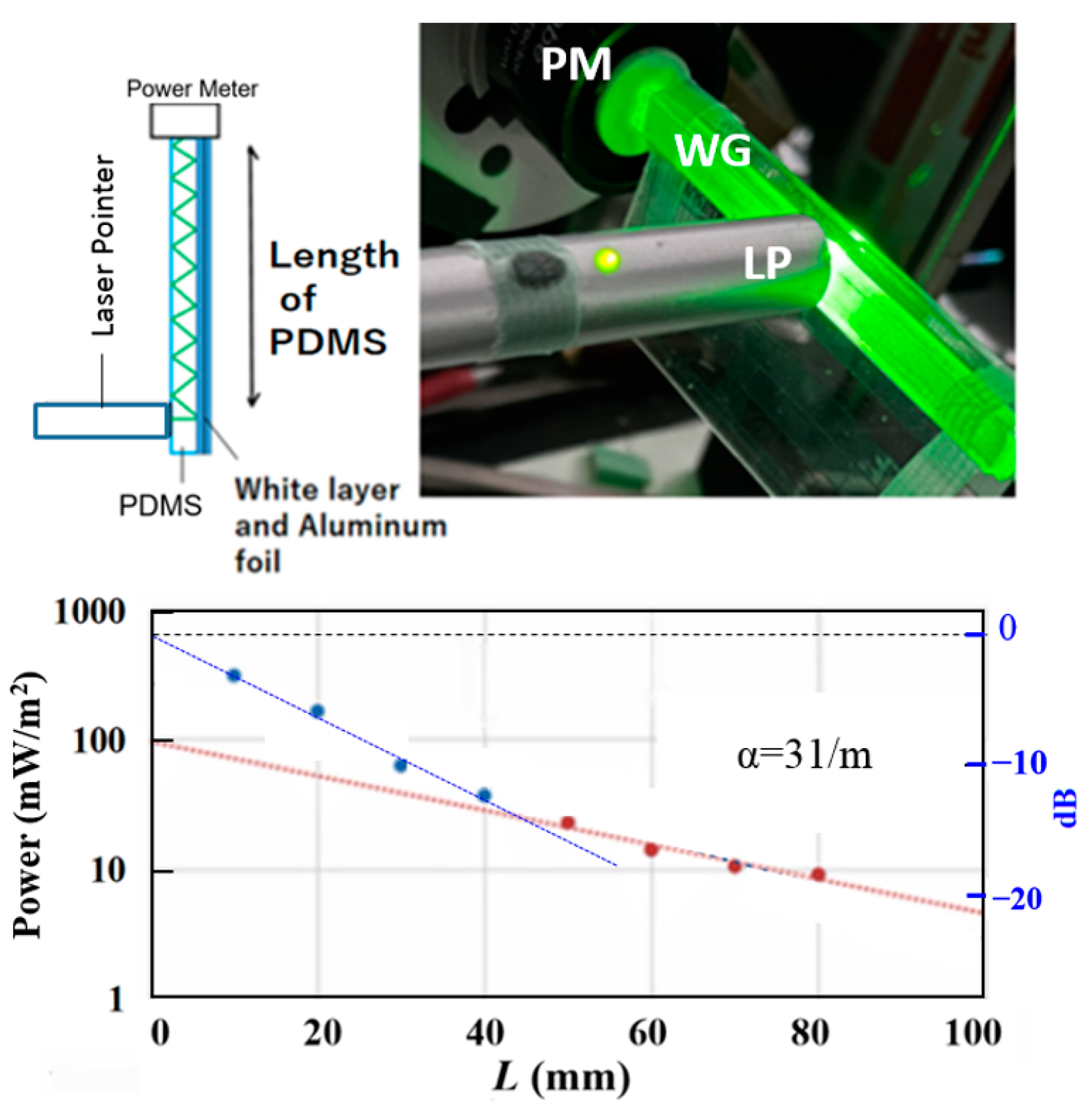
28]. It is, however, not an easy task to fabricate a DTSWG with a very fine structure; thus, we decided to take another approach to establish a lamppost that can utilize solar power with 2DPRCS, albeit not necessarily with a high efficiency (this can be addressed in the near future by using 2DPRCS with DTSWG). Thus, we established the idea of light transmittance in a PDMS waveguide based on diffusive reflection provided by a white paper embedded in one side of the cladding layer of the waveguide. We constructed a PDMS planar waveguide where one side was covered with white paper, as shown in the inset of
Figure 4. In making such PDMS samples, we used a high-gloss color printing paper (white paper) for diffuse light reflection, and then placed aluminum foil on the back side of the white paper, as shown in the top left inset of
Figure 4, illustrating the waveguiding experiment of the light incident on the surface of the waveguide, whereby reflection of the light is repeated until it reaches the solar cell at the end of the waveguide. This system can be referred to as a reflection solar cell (RSC). The purpose of the RSC is indeed similar to that of the LSC, but the main difference is that the core of the waveguide has no light scatterers, which can lead to better waveguiding characteristics with respect to the waveguide’s core. In the experiment shown in
Figure 4, we placed an optical power meter instead of a solar cell. The top right inset of
Figure 4 depicts the experiment, in which we placed a laser pointer perpendicular to the PDMS waveguide and an optical power meter at one end of the waveguide. Upon changing the distance
L from the power meter to the position of the laser pointer, we measured the optical power at the end of the waveguide to analyze the waveguiding efficiency of the RSC. As shown by the blue circles in
Figure 4, the detected power dropped sharply when
L was less than 50 mm due to the extra optical loss that occurred when the laser pointer was close to the other end of the RSC. Thus, using the data (orange circles) for which
L was large enough, we estimated the optical loss coefficient α for the waveguide as ~31/m. This is higher by one order of magnitude than for the case of edge injection (shown in
Figure 2); the reflection layer structure was optimized by inserting an extra layer between PDMS and the white layer.
2.4. Cylindrical Waveguide for Reflection Solar Concentrator (RSC)
Next, we placed the RSC waveguide on the surface of a 50 mm diameter cylinder. The basic principle of the diffusive reflection experiment is the same as that shown in the top left inset of
Figure 4; however, here, we measured the power of the light at one end of the RSC waveguide placed around the cylinder after a series of reflections depending on the distance between the power meter and the light injection point by the laser pointer set vertical to the cylindrical RSC waveguide, as shown in
Figure 5. Here, we also minimized the possible air gap between the laser and the PDMS waveguide, maintaining it during the experiment. The red line was obtained from red solid circles excluding the data from positions near the edges to extract the intrinsic characteristics of the waveguide, while the blue line was fitted to the blue solid circles to extrapolate the value at
L = 0. The distance along the circumference between the beam injection position and the power meter at the edge ranged from 7 mm to 73 mm. We could estimate the optical losses in PDMS-based cylindrical RSC waveguides to be α = 27/m for red, α = 45/m for green, and α = 41/m for blue. The smaller α for red was presumably due to the larger difference between the wavelength and scatterer in the white paper. Since these values of α (27–45/m) are not necessarily much deteriorated from that (α = 31/m) obtained in the case of a planar waveguide (shown in
Figure 4), the new cylindrical waveguide is promising. The bending configuration does not affect α much even when compared to the case of the planar waveguide. In addition, by using the RSC waveguide around a lamppost, we would be able to realize a new 2DPRCS because the power available is twofold greater when utilizing both clockwise and counterclockwise propagating light.
2.5. Further Possible Improvement of 2DPRCS around Cylindrical Surface
2.5.1. Simulation for Nonconcentric Cylindrical Waveguide
In the cylindrical waveguide in
Figure 5, we can regard the waveguide as defined by two concentric circles because the thickness of the RSC waveguide placed around the cylinder is constant. Here, we should note that the nonconcentric cylindrical waveguide is another potentially important option to implement our 2DPRCS around the circumference of a streetlamp post, as shown in
Figure 1. This is because it becomes easier for the light to be totally reflected with the reflection angle increasing as the guided light propagates in a nonconcentric cylindrical waveguide, as shown in
Figure 6. Here,
R and
r are the radii of the outer and inner circles, respectively, and
d is the distance between the centers of those two circles. Because we need to maximize the efficiency of the waveguide achieving total reflection of light, we simulated the light reflection in the nonconcentric waveguide, and the results are shown in
Figure 6. In this type of waveguide, the reflection angle increases in a zigzag pattern during the propagation; hence, the reflection angle of light soon reaches above the critical angle of total reflection during propagation in the nonconcentric cylindrical waveguide, in marked contrast to the case of the concentric waveguide for which the reflection angle is constant. Thus, obtaining higher waveguiding efficiency is easier when we use cross-sectionally nonconcentric circle waveguides than when we use concentric waveguides.
2.5.2. Planar Tapered Waveguide Experiment
When the nonconcentric circle waveguide around a cylinder (see bottom inset of
Figure 6), cut at the thinnest and widest position, is placed into a planar configuration, we can obtain a tapered waveguide, as shown in
Figure 7. Therefore, we fabricated an asymmetric waveguide (WG) with periodic parabola mirrors (PPMs) [
11] using a tapered planar waveguide but using the concentric PPM configuration shown in
Figure 7a. The right and left sides of
Figure 7a show a picture and the design of the PPMs, respectively. The PPM was made using acryl-based 3D printing. The rectangular parallelepiped shown in
Figure 6 containing the PPM was 20 mm along x, 55 mm along y, and 6 mm along z. On the 3D-printed structure, Ag metal was vacuum-evaporated to establish the parabola mirrors. The mirror shape was carefully designed so as to never block the incoming light, and the focus point was located 0.6 mm below the bottom xy-plane of the rectangular parallelepiped. We simulated another type of RWG [
11] using the PPM described above with a tapered thin waveguide.
We cut a flat transparent cone with an apex angle of 166° and a refractive index of 1.6 into a rectangle that fit the PPM shown in
Figure 7a to be used as a thin tapered waveguide with the PPMs having rotational symmetry in the xy-plane. Then, we measured the optical field at the edge of the tapered waveguide (the top inset of
Figure 7b) with the PPMs immersed in water. Next, we put a Si solar cell at the edge of the tapered waveguide and measured the I–V characteristics of the solar cell as a concentrator system. As depicted in the bottom inset of
Figure 7b, with the PPM designed so as to not block the incoming light, a concentration factor of ~4 was obtained in this experiment, demonstrating the high potential of 2DPRCS. We investigated the PPM–tapered waveguide system as an example of 2DPRCS, featuring a naturally built concentrator system. The ability to harvest or integrate photons applies not only to uniformly distributed photons (e.g., sunlight) but also for δ-functions (e.g., laser beam profile), leading to robustness of the OWPT system against spatial beam fluctuations [
15,
16]. Note that this robustness is a direct consequence of 2DPRCS, where photoreception is decoupled from photoelectric conversion.
3. Multijunction Solar Cell Embedded in Nonconcentric Cylindrical Waveguide
For 2DPRCS, both waveguides and solar cells are needed. In the previous section, we discussed the waveguide; in this section, we show the results of the photovoltaic device (solar cell). Our ultimate goal is to realize a 2DPRCS that can decouple the site where light absorption occurs from the site where photoelectric conversion takes place [
10]. To maximize the efficiency of solar cells, we used multijunction, rather than single-junction solar cells.
Figure 8 shows the I–V characteristics of a solar cell [
29] made by a Taiwanese company. The size of the solar cell was 3 mm × 3 mm × 0.4 mm. The short-circuit currents were 5.4 mA and 4.1 mA for light incident on the front and back, respectively, while the open-circuit voltages were 8.1 V and 7.3 V, respectively.
The output electric power was slightly smaller presumably because the light enters through a transparent substrate film and adhesive material; however, as a whole, there was no real difference in performance when light was incident from both sides. Accordingly, we believe that this device can be used to create multijunction solar cells in the future [
10]. Thus, as shown in
Figure 9, we established a cylindrical 2DPRCS photovoltaic system, in which a multijunction solar cell was set up inside a nonconcentric cross-section waveguide, and the sunlight hitting the lamppost from all directions was directed to the multijunction solar cell through counterclockwise and clockwise routes. When two tapered waveguides are placed around the cylinder along the
circumference, the cross-section is as shown in
Figure 9 (left), in which two cross-sections of the tapered waveguide shown in the inset of
Figure 7b are combined, going form the south point to the north point around the lamppost, resulting in a nonconcentric circle in the xz-plane. This system can serve as a natural concentrator system that is expected to integrate very well with the multijunction system shown in
Figure 8a. As for the concentration ratio
R, the multijunction Si solar cell by MIH
TM VMJ worked best at
R ≈ 100; thus, we set the waveguide thickness to ~1–2 mm for a lamppost with a diameter of 50–60 mm. This concentrator photovoltaic system is possible for a system with a 2DPRCS featuring RWG consisting of DTSWG and a thin (2D) waveguide.
In general, the 2DPRCS frees us from the heavy use of semiconductors. By minimizing degeneracy, we can build new energy-efficient environmentally friendly systems [
30,
31] for achieving sustainable development goals (SDGs).
4. Conclusions
We proposed a cylindrical reflection solar concentrator (RSC) by implementing the two-dimensional photoreceptor-conversion scheme (2DPRCS), in which the photon collection part is decoupled from the photoelectric conversion part in space, but connected two-dimensionally by a thin (2D) waveguide. We identified PDMS as a potential material for RSC cylindrical waveguide fabrication. The new waveguide has discrete translational symmetry and can be used as a key component of concentrating photovoltaic systems.
PDMS-based waveguides were constructed, and the edge-input light transmission efficiency and diffuse reflection efficiency of the cylindrical PDMS were tested. We found that the intrinsic optical loss of our PDMS (~3 m−1) for a planar waveguide was low enough to be used for 2DPRCS. Although the optical loss of the cylindrical waveguide was larger by about an order of magnitude than the intrinsic loss, presumably due to the extrinsic effect caused by the unoptimized reflection at the white layer region of the waveguide, the loss of light was independent of whether the waveguide was flat or had a curvature of 25 mm radius. We also demonstrated the feasibility of nonconcentric waveguides compared to concentric waveguides using a simulation. The results showed that, after the light is incident, the reflection angle of the light inside the waveguide tends to increase, thus using the principle of total reflection to obtain a higher propagation efficiency than the concentric cylindrical waveguide. We also demonstrated that multijunction solar cells are suitable for 2DPRCS around a cylindrical surface. By combining multijunction solar cells with nonconcentric cylindrical waveguides, we can obtain a novel and efficient solar-cell system. Robustness of the optical wireless power transmission (OWPT) is achievable through 2DPRCS, in which the site of photoreception is decoupled from that of photoelectric conversion. With 2DPRCS, we can build new energy-efficient environmentally friendly systems for achieving sustainable development goals (SDGs).
The simulation and experimental results indicated that the new waveguide can serve as a key component for excellent photovoltaic concentration systems with high conversion efficiency. Using this new waveguide, the 2DPRCS is expected to be implemented around a cylindrical surface in the near future.


