Abstract
Photonic integrated circuits (PICs) have been a research hotspot in recent years. Programmable PICs that have the advantages of versatility and reconfigurability that can realize multiple functions through a common structure have been especially popular. Leveraging on-chip couplers and phase shifters, general-purpose waveguide meshes connected in different topologies can be manipulated at run-time and support a variety of applications. However, current waveguide meshes suffer from relatively a low cell amount and limited bandwidth. Here, we demonstrate a reconfigurable photonic integrated computing chip based on a quadrilateral topology network, where typical analog computing functions, including temporal differentiation, integration, and Hilbert transformation, are implemented with a processing bandwidth of up to 40 GHz. By configuring an optical path and changing the splitting ratio of the optical switches in the network, the functions can be switched and the operation order can be tuned. This approach enables wideband analog computing of large-scale PICs in a cost-effective, ultra-compact architecture.
1. Introduction
With the rapid development of information technology and the continuous emergence of new frontiers such as the Internet of Things, autonomous driving, and virtual reality, the demand for network capacity in various industries has witnessed a great surge, which will inevitably lead to higher requirements for the transmission bandwidth and speed of communication systems [1,2]. To serve these needs, photonic integrated circuits (PICs) have become a promising and powerful solution thanks to their unique combined characteristics of low cost, fast speed, large bandwidth, small footprint, and high power efficiency [3,4]. Additionally, PICs have enabled various application scenarios involving telecommunications, microwave photonics, artificial intelligence, and quantum computing [5,6,7,8]. However, traditional PICs are mainly designed for specific applications, and the lack of variability presents problems in terms of having a single function and poor versatility [9,10]. Programmable PICs [11,12,13] are of particular interest in the reconfiguration of various functions, thus avoiding the lengthy iterative process of traditional PICs’ design–fabrication–packaging–testing flow [14].
Programmable PICs can realize switching and tunability among multiple functions of the system by employing electrical control signals [15,16,17,18], which superbly reduce the cost and increase the flexibility of the hardware configuration [19,20,21,22,23,24]. A reconfigurable photonic signal processor has been realized based on a semiconductor optical amplifier (SOA)-activated InP circuit [25]. The optical path can be switched between the on or off state by changing the forward and reverse currents injected to the SOA. However, the function is hard to enrich while keeping the same layout. A more universal architecture is to employ a field programmable photonic gate array which is comprised of configured interconnections and an array of photonic analog blocks [26]. Based on two-dimensional (2D) waveguide mesh networks, several representative advances have been reported in the implementation of various functions via different material platforms [27,28,29,30]. Zhuang et al. proposed a programmable optical framework based on a square-shaped waveguide mesh connected by a grid of Mach–Zehnder interferometers (MZIs) [31]. Each MZI can be independently controlled by inducing external electronic signals to synthesize a desired light path through the mesh and thereby enable a diversity of signal processing functions. However, it features a restricted bandwidth and a limited cell number. For example, the free spectral range (FSR) is 14 GHz, and a large cell area occupies a large footprint on the Si3N4 platform. Reconfigurable waveguide mesh on a silicon platform has also been demonstrated, with seven hexagonal MZI waveguide cells providing more functionalities and an improved FSR of 18.4 GHz [32]. Although the field of reconfigurable optical computing chips has made rapid development and great improvement, challenges remain in terms of large-scale photonic topology networks being implemented in reconfigurable ultra-wideband photonic analog computing. For networks with higher bandwidth and smaller coverage cells, a general-purpose waveguide mesh core should be suited to programmability.
In this paper, we present a reconfigurable analog optical signal computing chip based on a quadrilateral MZI topology network on a silicon platform. Utilizing a fabricated mesh composed of nine quadrilateral waveguide cells, the light path can be tuned at run-time and three typical computing functions are experimentally demonstrated (temporal differentiation, Hilbert transformation, and integration). The functions can be switched and the operation order can be tuned with a wide processing bandwidth of up to 40 GHz. This network architecture enables wideband operation with complementary metal–oxide–semiconductor (CMOS) compatibility, and also provides scalable and common integrated optical hardware that can meet the needs of multiple optical computing in a simple and compact structure.
2. Methods
The basic building block for universal programmable PICs is based on a 2 × 2 MZI-configured optical gate, as depicted in Figure 1a, which is constituted by two multimode interferometers (MMIs) and two parallel waveguides loaded with phase shifters, Φupper and Φlower, on each arm. The linear transmission matrix can be written as:
where θ is (Φupper − Φlower)/2 and Δ is (Φupper + Φlower)/2. It can be seen that the value of θ determines the splitting ratio of the MZI, and the value of Δ determines the phase shift of the MZI. Figure 1b shows three typical states of the optical gate. When the value of θ is 0, the MZI unit is in the cross state, and when the value of θ is π/2, the MZI unit is in the bar state as an optical switch. Otherwise, the MZI unit will split light with a specific splitting ratio as a tunable coupler. The direction and phase of light flow in the MZI can be changed by adjusting the thermal electrodes on the two arms of the MZI. According to the above-mentioned principle, optical signal control with an arbitrary splitting ratio and arbitrary phase shift can be realized by using this basic unit. Replicating these basic units in a certain 2D topology can form waveguide meshes. Figure 1c–e show three common network structures, including a hexagonal topology, quadrilateral topology, and triangular topology. Among them, the hexagonal device has excellent performance in terms of power consumption and reconfigurability and has been highly praised by many researchers. The propagation direction of the quadrilateral structure is compatible with the traditional transmission network, and it offers a larger bandwidth in the confined space. In contrast, the triangular structure has certain limitations in terms of reconstruction diversity. Thus, we herein choose the quadrilateral waveguide mesh as the interconnection topology architecture. See Appendix A for more comparisons of these three topologies.
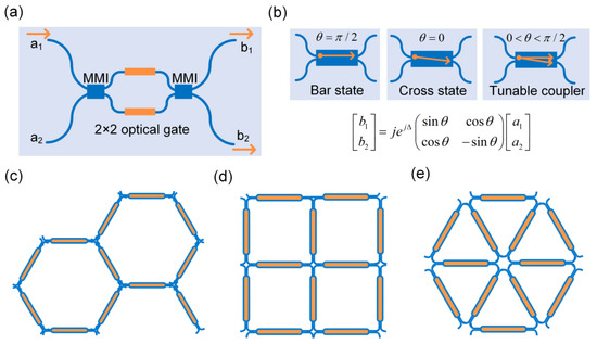
Figure 1.
Universal 2 × 2 optical gate. (a) The magnitude and phase of output light b1 and b2 are controlled through the 2 × 2 optical gate. (b) The gate can be tuned in bar, cross, and tunable coupler states. (c–e) Reconfigurable waveguide meshes based on a hexagonal topology (c), quadrilateral topology (d), and triangular topology (e).
Figure 2a shows the schematic of the proposed 3 × 3 waveguide mesh architecture, which is composed of 9 quadrilateral cells, 20 optical ports, and 52 phase shifters. By properly setting the electronic control signals loaded on the thermal heaters, the MZI unit can be configured in any state (as shown in Figure 2b), allowing for the synthesis of various optical paths, including both finite and infinite impulse response as required. Therefore, different transfer functions can be constructed to implement analog signal computing. The designed chip has an overall size of 3.3 × 3 mm2. The length of the basic MZI unit is set to 390 µm and is composed of two MMIs and the connected waveguide so as to meet the goal of a large bandwidth of over 40 GHz. The length and width of the MMI are 27.5 µm and 2.8 µm, respectively. The chip is fabricated on a silicon-on-insulator (SOI) wafer with 220 nm thick top silicon and a 2 µm thick buried oxide layer. TiN heaters are deposited with a width of 2.5 µm on top of the silicon planar waveguide serving as the thermo-optic phase shifters. Figure 2c,d present the microscope images of the fabricated chip and a zoomed-in view of a test MZI cell. Figure 2e shows the hybrid optoelectronic package of the chip. The chip is wire-bonded to a printed circuit board (PCB) and a thermoelectric cooler (TEC) segment is assembled underneath, which was connected to a commercial TEC controller to mandate careful control of chip temperature to 24 °C during the experiment.
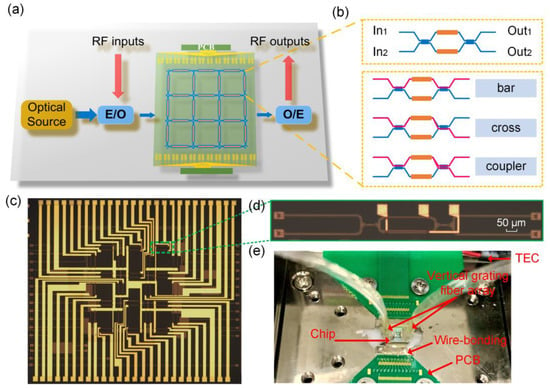
Figure 2.
Schematic of the proposed programmable photonic integrated computing chip. (a) Reconfigurable hardware core and the possible electrical and optical peripherals. (b) Schematic representation of the basic MZI unit. (c) Microscope image of the fabricated photonic computing chip. (d) Zoomed-in image of a basic optical gate. (e) Overall photo of the packaged chip with TEC temperature control.
3. Results
We first characterized the basic MZI unit. Insertion loss of 0.7 dB ensures that a certain degree of interconnection complexity can be achieved. For large-scale waveguide meshes, the homogeneous performance of waveguide uniformity is rather important. The extinction ratio is over 36 dB, with a π-shift power of 21 mW. The chip is characterized by the optical spectrum analyzer (OSA, Yokokawa, AQ6370C) to verify its reconfigurability. A homemade multi-channel programmable power supply is used to control the state of each MZI unit to construct different photonic circuits. The overall insertion losses for temporal differentiation, Hilbert transformation, and integration are 1.6 dB, 2 dB, and 10 dB, respectively. The relevant spectra are shown in the next subsection. Figure 3 shows the experimental setup. For temporal differentiation and Hilbert transformation, a 40-bit “0101” signal with a speed of 30 GHz is generated by the bit pattern generator (BPG) and loaded onto the intensity modulator. High nonlinear fiber (HNLF) and single-mode fiber (SMF) are subsequently used to compress the output signal to generate an ultra-narrow optical pulse with a full width at half maximum (FWHM) less than 25 ps. Polarization controllers (PCs) are used to match the polarization state and maximize the power. The output signal is amplified by an erbium-doped fiber amplifier (EDFA), with a variable optical attenuator (VOA) then used to control the optical power. The signal is then detected by a high-speed photodetector (PD, Finisar, XPDV2120R) and the waveform is finally observed by an oscilloscope (OSC, Keysight, N1000A). For the temporal integration, a homemade mode-locked laser (MLL) source with a repetition rate of 50 MHz was used to provide a femtosecond pulse. The output signal is filtered by a tunable optical bandpass filter (BPF) to filter out a range of resonant peaks before photodetection.
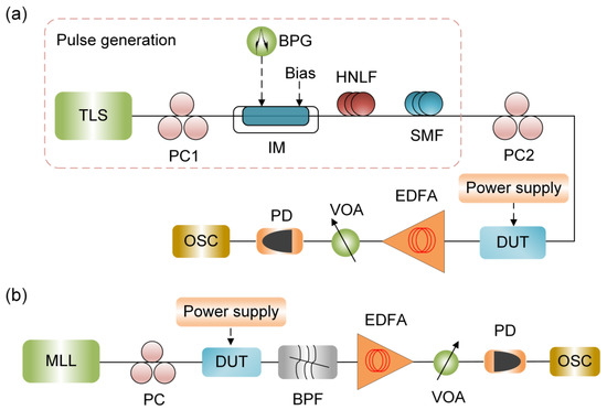
Figure 3.
Experimental setup for temporal differentiation, Hilbert transformation (a), and temporal integration (b). TLS, tunable laser source; PC, polarization controller; BPG, bit pattern generator; IM, intensity modulator; HNLF, high nonlinear fiber; SMF, single-mode fiber; DUT, device under test; EDFA, erbium-doped fiber amplifier; VOA, variable optical attenuator; PD, photodetector; OSC, oscilloscope; MLL, mode-locked laser; BPF, bandpass filter.
3.1. Photonic Temporal Differentiation
A photonic temporal differentiation has applications in many fields, such as waveform shaping, pulse generation, and image edge detection [33,34,35]. The transfer function of an nth-order differentiator can be expressed as:
where , ω is optical angular frequency, n is the differentiation order, and ω0 is the carrier frequency of the processing signal. According to the formula, different orders of a temporal optical differentiator have different magnitude responses that are proportional to . The phase response has a jump of nπ at ω0. Such a transfer function can be implemented using an MZI. By adjusting the splitting ratio of the two arms of the structure, the amplitude response and phase jump of the MZI will also change; therefore, the order of the fractional differentiator can be tuned. The network is firstly configured to be an MZI, as shown in Figure 4a. Different color bars indicate the different statuses of the basic MZI unit. Figure 4b shows the corresponding circuit layout, which has an unbalanced arm length of two MZI units. In the experiment, a Gaussian pulse with an FWHM of 22.6 ps is coupled into the waveguide mesh. The measured transfer function (blue curve) of the differentiator and the optical spectrum of input pulse (red curve) are shown in Figure 4c and indicate an FSR of 80 GHz and a processing bandwidth of 40 GHz. The fractional order can be tuned by changing the amplitude splitting ratio of the coupler state MZI. Measured results (blue curve) and theoretical results (orange curve) are shown in Figure 4e–g. Three differentiated pulses corresponding to three differentiation orders of 0.76, 1, and 1.16 were respectively obtained. To evaluate the signal processing accuracy of the mesh, we define the processing error Err as the difference between the cosine similarity between the measured waveform and the theoretical waveform and 1, which is given by:
where is the time domain sequence of the measured waveform and is the time domain sequence of the theoretical waveform, both with a time window of one pulse period. The processing error mainly comes from two aspects. One is the difference between the ideal transfer function and the transmission spectrum implemented by the reconfigurable PICs. The other is the spectral width of the input signal. If the spectral width of the signal is far beyond the working bandwidth of the differentiator, it will bring a relatively large error. Using this formula, the errors between the experimental values and the theoretical values of different operation orders are calculated to be 2.01%, 2.58%, and 2.58%, respectively. A small processing error less than 3% is achieved.
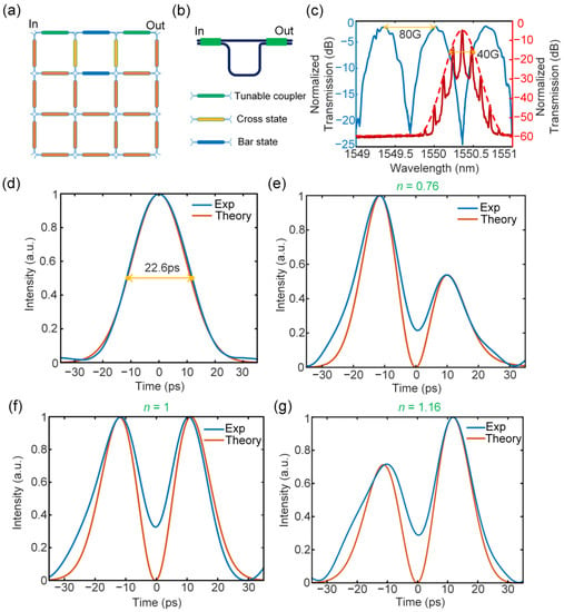
Figure 4.
Experimental results for fractional differentiation. (a) Waveguide mesh configuration diagram. (b) Mesh connection layout. (c) Measured transfer function of the reconfigured MZI (blue curve) and the optical spectrum of the Gaussian input (red curve). (d) The input Gaussian pulse with a temporal width of 22.6 ps. (e–g) The calculated (orange curve) and measured (blue curve) fractional differentiation of the input Gaussian pulse with fraction orders of 0.76 (e), 1 (f), and 1.16 (g).
3.2. Photonic Temporal Hilbert Transformation
Hilbert transformation [36,37] executes a phase regulation that is a fundamental signal processing operation for applications in single-sideband modulation, radar [38], 5G, and 6G communications [39]. The transfer function of an nth-order Hilbert transformer can be expressed as:
It can be seen that the ideal Hilbert transformation has a magnitude response of 1 and a phase jump of either π or a fraction of π at the filter’s central frequency. Therefore, a fractional Hilbert transformer can be implemented using a critical coupling MRR. Figure 5a,b show the waveguide mesh configuration and the circuit layout, with MZI status labeled with different colors. An MRR with a cavity length of four MZI units was built. The transfer function has an FSR of 40 GHz and a Q factor of 6.0 × 10⁵, as shown in Figure 5c. If the bandwidth is narrow enough, the spectral response will be close to a complete pass, leading a smaller error. Here, tunable fractional Hilbert transformation with tunable orders at 1, 0.91, and 1.04 for the same input Gaussian pulse is present, as shown in Figure 5e–g. Similar to the fractional order differentiator, the fractional order of the Hilbert transformer can also be tuned through the coupling coefficient of the MRR by altering the loaded voltage on the MZI unit as a tunable coupler. The blue curve is the experimental measured waveform and the orange curve is the theoretical calculation waveform. The operation error is also measured by the above formula, and the corresponding errors are 0.85%, 0.78%, and 0.57%, respectively. Good agreement with an error less than 1% was achieved.
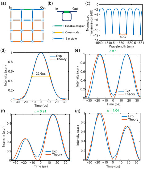
Figure 5.
Experimental results for Hilbert transformation. (a) Waveguide mesh configuration diagram. (b) Mesh connection layout. (c) Measured transfer function of the reconfigured MRR. (d) The input Gaussian pulse with a temporal width of 22.6 ps. (e–g) The calculated (orange curve) and measured (blue curve) fractional differentiation of the input Gaussian pulse with fraction orders of 1 (e), 0.91 (f), and 1.04 (g).
3.3. Photonic Temporal Integration
A photonic temporal integration performs the time integral of an arbitrary input that can be applied to scenarios such as photonic bit counting [40], optical memory [41], and analog computing of differential equations [42,43,44]. The transfer function of an ideal integrator can be expressed as:
The spectral transfer function of an ideal integrator can be realized by an add–drop MRR. The network configuration is presented in Figure 6a. The corresponding transmission spectrum is shown in Figure 6c with an operational bandwidth of 40 GHz. An optical Gaussian pulse generated by an MLL with a temporal width of 300 fs and a repetition rate of 50 MHz was used to verify the temporal integrator, as shown in Figure 6d. The integration time is an important indicator when measuring the integration effect. Figure 6e shows that integration time was measured to be 77 ps.
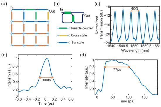
Figure 6.
Experimental results for temporal integration. (a) Waveguide mesh configuration diagram. (b) Mesh connection layout. (c) Measured transfer function of the reconfigured add–drop MRR. (d) The input Gaussian pulse with a temporal width of 300 fs. (e) The integration of the Gaussian pulse with an integration time of 77 ps.
4. Discussion
Table 1 presents a comprehensive comparison of our proposed scheme with the state-of-art programmable PICs. It can be seen that our approach exhibits high overall performance by offering the largest processing bandwidth alongside a simple passive waveguide mesh and compact size. Our work surpasses the bandwidth and dimension capabilities of existing waveguide meshes, marking a significant step towards enabling wideband analog computing with large-scale PICs. In contrast to application-specific devices, programmable PICs provide reconfigurable structures that use the same hardware configuration, thus allowing for versatility in a range of applications. In addition, the proposed 3 × 3 quadrilateral waveguide mesh is capable of more functionalities thanks to its feed-backward loops, such as photonic filtering, optical beamforming, and pulse shaping in the field of RF signal processing. Moreover, through multiple input and output ports, linear unitary transformation can also be implemented. The current approach relies on a TEC module to accelerate heat dissipation and reduce thermal crosstalk. By incorporating electro-optic phase shifters, the tuning mechanism can be further optimized in terms of speed, power consumption, and unit length.

Table 1.
Comparison of programmable photonic circuits.
In summary, we have designed, fabricated, and demonstrated a reconfigurable photonic integrated analog computing chip based on a 3 × 3 network topology. By building MZI basic units through a quadrilateral architecture, the chip is fully circuit programmable and has the potential to implement a variety of complex functions. Typical functions incorporating temporal differentiation, integration, and Hilbert transformation with a tunable order were realized. Experimental results prove that the network offers good reconfigurability and tunability at a processing bandwidth of over 40 GHz. Owing to the remarkably large scale of network cells, the functions of the proposed waveguide mesh are not limited by a specific application, which is universal and can be configured to execute more fields, including but not limited to reconfigurable delay lines, optical beamforming, finite and infinite photonic filtering, and linear matrix transformation.
Author Contributions
Conceptualization, Y.Y. and Y.W.; methodology, Y.Y and Y.W.; data curation, Y.Y.; writing—original draft preparation, Y.Y.; writing—review and editing, Y.W., J.D. and M.L.; supervision, X.Z.; funding acquisition, J.D. All authors have read and agreed to the published version of the manuscript.
Funding
This research was supported by the National Key Research and Development Project of China (2018YFB2201901), the National Natural Science Foundation of China (U21A20511, 62075075), and the Innovation Project of Optics Valley Laboratory (Grant No. OVL2021BG001).
Institutional Review Board Statement
Not applicable.
Informed Consent Statement
Not applicable.
Data Availability Statement
The data that support the findings of this study are available from the corresponding author upon reasonable request.
Conflicts of Interest
The authors declare no conflict of interest.
Appendix A
For a processing unit, its FSR directly determines the maximum signal processing bandwidth, which can be expressed as:
where ng is the group refractive index and Lneff is the length of the effective optical path. Taking the processing bandwidth of 40 GHz as the primary indicator, the length of the MZI unit is calculated to be 390 µm. Here, we compared the number of units required to construct MZI and MRR structures with hexagonal, quadrilateral, and triangular topologies, respectively, and some figures of merit are also compared, as shown in Table A1. It can be seen that the hexagonal waveguide mesh has the highest reconfigurability since it offers the minimum reconfigurable resolution step. However, as far as bandwidth is concerned, regarding the configurations of both MZIs and MRRs, the quadrilateral waveguide mesh is optimal for providing the maximum achievable FSR.

Table A1.
Comparison of parameters for constructing MZIs and MRRs with different topologies.
Table A1.
Comparison of parameters for constructing MZIs and MRRs with different topologies.
| Figure of Merit | Hexagonal | Quadrilateral | Triangular |
|---|---|---|---|
| Possible arm length mismatch for constructing MZIs/unit | 2n | 2,4n | 3n |
| Possible cavity length for constructing MRRs/unit | 6,10 + 2n | 4n | 3n |
| MZI reconfiguring resolution step/unit | 2 | 4 | 3 |
| MRR reconfiguring resolution step/unit | 2 | 4 | 3 |
| MZI maximum achievable FSR/GHz | 80 | 80 | 53.3 |
| MRR maximum achievable FSR/GHz | 26.67 | 40 | 53.3 |
References
- Tsai, C.-W.; Lai, C.-F.; Chao, H.-C.; Vasilakos, A.V. Big data analytics: A survey. J. Big Data 2015, 2, 21. [Google Scholar] [CrossRef]
- Chen, X.; Milosevic, M.M.; Stankovic, S.; Reynolds, S.; Bucio, T.D.; Li, K.; Thomson, D.J.; Gardes, F.; Reed, G.T. The Emergence of Silicon Photonics as a Flexible Technology Platform. Proc. IEEE 2018, 106, 2101–2116. [Google Scholar] [CrossRef]
- Coldren, L.A.; Nicholes, S.C.; Johansson, L.; Ristic, S.; Guzzon, R.S.; Norberg, E.J.; Krishnamachari, U. High Performance InP-Based Photonic ICs—A Tutorial. J. Light. Technol. 2011, 29, 554–570. [Google Scholar] [CrossRef]
- Heck, M.J.R.; Bauters, J.F.; Davenport, M.L.; Doylend, J.K.; Jain, S.; Kurczveil, G.; Srinivasan, S.; Tang, Y.; Bowers, J.E. Hybrid Silicon Photonic Integrated Circuit Technology. IEEE J. Sel. Top. Quantum Electron. 2013, 19, 6100117. [Google Scholar] [CrossRef]
- Zhang, W.; Yao, J. Photonic integrated field-programmable disk array signal processor. Nat. Commun. 2020, 11, 406. [Google Scholar] [CrossRef]
- Shen, Y.; Harris, N.C.; Skirlo, S.; Prabhu, M.; Baehr-Jones, T.; Hochberg, M.; Sun, X.; Zhao, S.; Larochelle, H.; Englund, D.; et al. Deep learning with coherent nanophotonic circuits. Nat. Photonics 2017, 11, 441–446. [Google Scholar] [CrossRef]
- Harris, N.C.; Steinbrecher, G.R.; Prabhu, M.; Lahini, Y.; Mower, J.; Bunandar, D.; Chen, C.; Wong, F.N.C.; Baehr-Jones, T.; Hochberg, M.; et al. Quantum transport simulations in a programmable nanophotonic processor. Nat. Photonics 2017, 11, 447–452. [Google Scholar] [CrossRef]
- Qiang, X.; Zhou, X.; Wang, J.; Wilkes, C.M.; Loke, T.; O’Gara, S.; Kling, L.; Marshall, G.D.; Santagati, R.; Ralph, T.C.; et al. Large-scale silicon quantum photonics implementing arbitrary two-qubit processing. Nat. Photonics 2018, 12, 534–539. [Google Scholar] [CrossRef]
- Wang, J.; Shen, H.; Fan, L.; Wu, R.; Niu, B.; Varghese, L.T.; Xuan, Y.; Leaird, D.E.; Wang, X.; Gan, F.; et al. Reconfigurable radio-frequency arbitrary waveforms synthesized in a silicon photonic chip. Nat. Commun. 2015, 6, 5957. [Google Scholar] [CrossRef]
- Jiang, H.; Yan, L.; Marpaung, D. Chip-based arbitrary radio-frequency photonic filter with algorithm-driven reconfigurable resolution. Opt. Lett. 2018, 43, 415–418. [Google Scholar] [CrossRef] [PubMed]
- Capmany, J.; Pérez, D. Programmable Integrated Photonics; Oxford University Press: Oxford, UK, 2020. [Google Scholar] [CrossRef]
- Bogaerts, W.; Perez, D.; Capmany, J.; Miller, D.A.B.; Poon, J.; Englund, D.; Morichetti, F.; Melloni, A. Programmable photonic circuits. Nature 2020, 586, 207–216. [Google Scholar] [CrossRef] [PubMed]
- Xu, X.; Ren, G.; Feleppa, T.; Liu, X.; Boes, A.; Mitchell, A.; Lowery, A.J. Self-calibrating programmable photonic integrated circuits. Nat. Photonics 2022, 16, 595–602. [Google Scholar] [CrossRef]
- Carroll, L.; Lee, J.-S.; Scarcella, C.; Gradkowski, K.; Duperron, M.; Lu, H.; Zhao, Y.; Eason, C.; Morrissey, P.; Rensing, M.; et al. Photonic Packaging: Transforming Silicon Photonic Integrated Circuits into Photonic Devices. Appl. Sci. 2016, 6, 426. [Google Scholar] [CrossRef]
- Annoni, A.; Guglielmi, E.; Carminati, M.; Ferrari, G.; Sampietro, M.; Miller, D.A.; Melloni, A.; Morichetti, F. Unscrambling light-automatically undoing strong mixing between modes. Light. Sci. Appl. 2017, 6, e17110. [Google Scholar] [CrossRef]
- Pérez, D.; Gasulla, I.; Capmany, J. Software-defined reconfigurable microwave photonics processor. Opt. Express 2015, 23, 14640–14654. [Google Scholar] [CrossRef] [PubMed]
- Xie, Y.; Geng, Z.; Zhuang, L.; Burla, M.; Taddei, C.; Hoekman, M.; Leinse, A.; Roeloffzen, C.G.H.; Boller, K.-J.; Lowery, A.J. Programmable optical processor chips: Toward photonic RF filters with DSP-level flexibility and MHz-band selectivity. Nanophotonics 2017, 7, 421–454. [Google Scholar] [CrossRef]
- Miller, D.A.B. Perfect optics with imperfect components. Optica 2015, 2, 747. [Google Scholar] [CrossRef]
- Miller, D.A.B. Self-configuring universal linear optical component [Invited]. Photonics Res. 2013, 1, 1–15. [Google Scholar] [CrossRef]
- Clements, W.R.; Humphreys, P.C.; Metcalf, B.J.; Kolthammer, W.S.; Walmsley, I.A. Optimal design for universal multiport interferometers. Optica 2016, 3, 1460–1465. [Google Scholar] [CrossRef]
- Harris, N.C.; Carolan, J.; Bunandar, D.; Prabhu, M.; Hochberg, M.; Baehr-Jones, T.; Fanto, M.L.; Smith, A.M.; Tison, C.C.; Alsing, P.M.; et al. Linear programmable nanophotonic processors. Optica 2018, 5, 1623–1631. [Google Scholar] [CrossRef]
- Zheng, D.; Doménech, J.D.; Pan, W.; Zou, X.; Yan, L.; Pérez, D. Low-loss broadband 5 × 5 non-blocking Si3N4 optical switch matrix. Opt. Lett. 2019, 44, 2629–2632. [Google Scholar] [CrossRef]
- Miller, D.A.B. Self-aligning universal beam coupler. Opt. Express 2013, 21, 6360–6370. [Google Scholar] [CrossRef]
- Ribeiro, A.; Ruocco, A.; Vanacker, L.; Bogaerts, W. Demonstration of a 4 × 4-port universal linear circuit. Optica 2016, 3, 1348–1357. [Google Scholar] [CrossRef]
- Liu, W.; Li, M.; Guzzon, R.S.; Norberg, E.J.; Parker, J.S.; Lu, M.; Coldren, L.A.; Yao, J. A fully reconfigurable photonic integrated signal processor. Nat. Photonics 2016, 10, 190–195. [Google Scholar] [CrossRef]
- Perez, D.; Gasulla, I.; Capmany, J. Field-programmable photonic arrays. Opt. Express 2018, 26, 27265–27278. [Google Scholar] [CrossRef] [PubMed]
- Perez-Lopez, D.; Lopez, A.; DasMahapatra, P.; Capmany, J. Multipurpose self-configuration of programmable photonic circuits. Nat. Commun. 2020, 11, 6359. [Google Scholar] [CrossRef] [PubMed]
- Perez, D.; Gasulla, I.; Capmany, J.; Soref, R.A. Reconfigurable lattice mesh designs for programmable photonic processors. Opt. Express 2016, 24, 12093–12106. [Google Scholar] [CrossRef] [PubMed]
- Perez, D.; Gasulla, I.; Fraile, F.J.; Crudgington, L.; Thomson, D.J.; Khokhar, A.Z.; Li, K.; Cao, W.; Mashanovich, G.Z.; Capmany, J. Silicon Photonics Rectangular Universal Interferometer. Laser Photonics Rev. 2017, 11, 1700219. [Google Scholar] [CrossRef]
- Pérez, D.; Capmany, J. Scalable analysis for arbitrary photonic integrated waveguide meshes. Optica 2019, 6, 19–27. [Google Scholar] [CrossRef]
- Zhuang, L.; Roeloffzen, C.G.H.; Hoekman, M.; Boller, K.-J.; Lowery, A.J. Programmable photonic signal processor chip for radiofrequency applications. Optica 2015, 2, 854–859. [Google Scholar] [CrossRef]
- Pérez, D.; Gasulla, I.; Crudgington, L.; Thomson, D.J.; Khokhar, A.Z.; Li, K.; Cao, W.; Mashanovich, G.Z.; Capmany, J. Multipurpose silicon photonics signal processor core. Nat. Commun. 2017, 8, 636. [Google Scholar] [CrossRef] [PubMed]
- Li, F.; Park, Y.; Azaña, J. Complete temporal pulse characterization based on phase reconstruction using optical ultrafast differentiation (PROUD). Opt. Lett. 2007, 32, 3364–3366. [Google Scholar] [CrossRef] [PubMed]
- Park, Y.; Azaña, J.; Slavík, R. Ultrafast all-optical first- and higher-order differentiators based on interferometers. Opt. Lett. 2007, 32, 710–712. [Google Scholar] [CrossRef]
- Mathieu, B.; Melchior, P.; Oustaloup, A.; Ceyral, C. Fractional differentiation for edge detection. Signal Process. 2003, 83, 2421–2432. [Google Scholar] [CrossRef]
- Tan, M.; Mitchell, A.; Moss, D.J.; Xu, X.; Corcoran, B.; Wu, J.; Boes, A.; Nguyen, T.G.; Chu, S.T.; Little, B.E.; et al. Microwave and RF Photonic Fractional Hilbert Transformer Based on a 50 GHz Kerr Micro-Comb. J. Light. Technol. 2019, 37, 6097–6104. [Google Scholar] [CrossRef]
- Shahoei, H.; Dumais, P.; Yao, J. Continuously tunable photonic fractional Hilbert transformer using a high-contrast germanium-doped silica-on-silicon microring resonator. Opt. Lett. 2014, 39, 2778–2781. [Google Scholar] [CrossRef]
- Ghelfi, P.; Laghezza, F.; Scotti, F.; Serafino, G.; Capria, A.; Pinna, S.; Onori, D.; Porzi, C.; Scaffardi, M.; Malacarne, A.; et al. A fully photonics-based coherent radar system. Nature 2014, 507, 341–345. [Google Scholar] [CrossRef] [PubMed]
- Waterhouse, R.; Novack, D. Realizing 5G: Microwave Photonics for 5G Mobile Wireless Systems. IEEE Microw. Mag. 2015, 16, 84–92. [Google Scholar] [CrossRef]
- Carolan, J.; Harrold, C.; Sparrow, C.; Martín-López, E.; Russell, N.J.; Silverstone, J.W.; Shadbolt, P.J.; Matsuda, N.; Oguma, M.; Itoh, M.; et al. Universal linear optics. Science 2015, 349, 711–716. [Google Scholar] [CrossRef] [PubMed]
- Hill, M.T.; Dorren, H.J.S.; de Vries, T.; Leijtens, X.J.M.; den Besten, J.H.; Smalbrugge, B.; Oei, Y.-S.; Binsma, H.; Khoe, G.-D.; Smit, M.K. A fast low-power optical memory based on coupled micro-ring lasers. Nature 2004, 432, 206–209. [Google Scholar] [CrossRef]
- Ferrera, M.; Park, Y.; Razzari, L.; Little, B.E.; Chu, S.T.; Morandotti, R.; Moss, D.J.; Azana, J. On-chip CMOS-compatible all-optical integrator. Nat. Commun. 2010, 1, 29. [Google Scholar] [CrossRef] [PubMed]
- Ferrera, M.; Park, Y.; Razzari, L.; Little, B.E.; Chu, S.T.; Morandotti, R.; Moss, D.J.; Azaña, J. All-optical 1st and 2nd order integration on a chip. Opt. Express 2011, 19, 23153–23161. [Google Scholar] [CrossRef] [PubMed]
- Zangeneh-Nejad, F.; Fleury, R. Topological analog signal processing. Nat. Commun. 2019, 10, 2058. [Google Scholar] [CrossRef] [PubMed]
Disclaimer/Publisher’s Note: The statements, opinions and data contained in all publications are solely those of the individual author(s) and contributor(s) and not of MDPI and/or the editor(s). MDPI and/or the editor(s) disclaim responsibility for any injury to people or property resulting from any ideas, methods, instructions or products referred to in the content. |
© 2023 by the authors. Licensee MDPI, Basel, Switzerland. This article is an open access article distributed under the terms and conditions of the Creative Commons Attribution (CC BY) license (https://creativecommons.org/licenses/by/4.0/).