1. Introduction
To date, several technologies for the production of ordered arrays of carbon nanotubes (CNTs) with controlled parameters have been established [
1,
2,
3,
4,
5]. Such structures are of great practical interest for generating and controlling electromagnetic radiation. In particular, they could be used to design compact sources of coherent terahertz (THz) radiation [
6,
7,
8,
9,
10].
Such technical solutions exploit the following unique properties of CNTs:
- (a)
Individual CNTs (and their arrays) are capable of conducting currents of high density (over 10 A/mm
2 in direct current (DC) and 10
9 A/mm
2 in pulsed modes) [
11,
12];
- (b)
CNTs support propagation of “fast” drift currents with a velocity of about 10
6 m/s (approximately equal to the Fermi velocity) [
13,
14];
- (c)
CNTs support the propagation of ultraslow (with a velocity down to ~10
6 m/s) surface plasmon polaritons (SPPs) with a long mean free path [
15,
16,
17,
18,
19].
It is important that the huge values of the wavenumber associated with slow SPPs hinder their excitation using standard optical techniques (for example, using prisms in the Otto and Kretschmann geometry). The huge SPP effective refractive index leads to its localization within the plasmonic waveguide. The possible solution in this case could be an excitation of SPPs in the ordered CNT arrays by one or two laser beams. The beating of two laser beams with detuned frequencies is widely used for THz generation [
7,
8,
20,
21,
22]. In particular, in [
22] we proposed a scheme for exciting SPPs in a CNT array irradiated by two counter-propagating laser beams with slightly different frequencies in the near-infrared range. The analysis of phase-matching conditions for this wave process shows that by changing the angles of incidence of the laser beams on the structure under study, one can achieve a match between the length of the nanotubes in the array and the wavelength of the laser sources.
To enhance the efficiency of converting optical radiation into terahertz radiation, we propose using the effect of amplifying SPPs with a drift current. This effect has been reported in [
23,
24,
25,
26,
27] for SPPs in single-walled CNTs and other graphene-containing structures. SPP amplification occurs when the condition of synchronism is met, when the SPP phase velocity is close to the drift velocity of charge carriers in CNTs. This amplification can not only compensate the SPP attenuation but exceed the value of ohmic losses by several orders of magnitude [
27]. These properties of the CNT arrays could potentially be used to design traveling-wave tube-type amplifiers or backward-wave tube-type oscillators [
15]. However, the inhomogeneity of the gain spectrum prevents the implementation of this idea. Different CNTs support slow SPP modes at different frequencies, so their simultaneous excitation leads to noise generation. This situation is similar to that of the first solid-state (ruby and neodymium) lasers when the appearance of whispering gallery modes on the surface of active elements (cylindrical rods) led to the disruption of generation [
28]. To prevent this effect, one can either use an external resonator providing a high Q-factor for modes of a particular frequency or seeding with a coherent laser source exciting SPPs of a specific frequency [
22]. In the latter case, each CNT forms a resonator for SPPs due to the reflection of a plasmon from the CNT edge–vacuum interfaces.
In this work, we develop the concept of generators based on arrays of CNTs enabling the THz radiation of high power (both continuous and pulsed), in which a DC current flowing through the system is used as a pump, and the initial optical excitation of the system as a whole ensures the coherence of the emitted radiation. For this reason, we introduce current pumping into the two-beam THz generation scheme. Thus, unlike previously described THz generation schemes, we consider a CNT array simultaneously pumped by laser radiation and a drift current. To implement this idea, several interlinked tasks are to be considered:
- (1)
The coherent optical excitation of SPP modes in the CNT array by laser beams as a way for the initial excitation of the structure;
- (2)
The amplification of slow SPP modes by a drift current flowing through the CNTs;
- (3)
The generation of coherent THz radiation by an array of optically synchronized CNTs with DC electric current pumping.
In the following sections, we consider a scheme for the excitation and amplification of slow high-Q SPPs in the ordered double-walled CNT (DWCNT) array using two laser beams with slightly different frequencies. The dispersion dependences for the SPP modes in the DWCNTs are calculated numerically. It is shown that there are slow “interlayer” SPP modes with a relatively high Q-factor (up to 103). It is demonstrated that current amplification of super-slow SPPs in a DWCNT array is possible, and calculations of the SPP amplification increment under the phase synchronism condition with the drift current are performed. DWCNTs with SPPs generated in the array can be considered as antennas emitting radiation in the THz frequency range. The conditions of the current standing wave generation in the DWCNT array are elaborated. The power of THz radiation produced by the DWCNT array as a system of coherent emitters is estimated.
2. The CNT Conductivity Model
The study of the plasmonic properties of CNTs should rely on the model of CNT conductivity. Various models could describe the properties of multi-walled CNTs (MWCNTs). These are the effective medium model [
1,
4,
29,
30] and various ab initio models [
15,
16], with some degree of rigor, taking into account the influence of the structural features of CNTs on their conductivity. The structure of MWCNTs has been studied in detail by X-ray diffraction methods [
31]. MWCNTs are imagined as hollow or solid cylinders with diameters ranging from several nanometers to tens of nanometers with a distance between layers of 0.34 nm. Within the layer, carbon atoms are linked by strong covalent bonds. Atoms of different layers are bound by much weaker van der Waals forces [
32] that commonly have little effect on the electron shells and the band structure of individual graphene layers comprising MWCNTs [
33]. It is shown in Ref. [
34] that the static conductivity along the layers is much higher than the interlayer conductivity. Using the random phase approximation (RPA) method, the influence of the structural properties of CNTs, in particular, their chirality, on the plasmonic properties of single-walled CNTs has been analyzed [
17,
33]. In addition, the curvature of the walls of MWCNTs (rolled graphene layer) has practically no effect on the band structure for nanotubes with a diameter on the order of 1 nm or more.
Thus, to simulate the plasmonic properties of MWCNTs of a relatively large diameter, the frequency dependence of the conductivity
calculated for planar graphene [
35,
36] can be used. Up to frequencies on the order of tens of THz, the main role is played by the term
[
37], which determines the contribution of intraband transitions:
Here,
e is the electron charge,
is the Plank constant,
is the Boltzmann constant,
T is the temperature,
is the graphene chemical potential, and
is the momentum relaxation time. For numerical calculations, we use the following parameters:
T = 300 K,
= 0.2 eV и
0.1 meV [
38]. The used value of the chemical potential corresponds to the concentration of surface carriers
= 4 × 10
12 cm
–2 [
39], which means the doping level is one additional charge carrier per thousand carbon atoms [
33]. Under the condition
that is well satisfied for the chosen values of
and
T, Equation (1) transforms into the well-known Drude-type expression [
35]. In our calculations, we use a modified Drude-type formula:
where the denominator contains a term that takes into account the spatial dispersion in the electron gas associated with the finiteness of the perturbation propagation velocity [
19,
40]. In Equation (2),
is the Fermi velocity and
is the complex propagation constant of SPPs.
Thus, to study the plasmonic properties of MWCNTs with a diameter of 5–10 nm, it seems reasonable to model them as a set of independent nested layers with conductivity of the type given by Equation (2).
3. Dispersion Properties of SPP Modes in an Array of DWCNTs
The MWCNT model can describe complex waveguides formed by a set of conducting sheets. Therefore, the spectrum of SPP modes in MWCNTs is too complex and challenging to analyze. We limit our consideration to DWCNTs as the simplest MWCNTs that allow us to reveal the main regularities in the interaction of MWCNTs with electromagnetic radiation. The dispersion properties of the SPPs in arrays of DWCNTs have been studied within the conductivity model given by Equation (2), and the research methodology has been described in Ref. [
18]. It should be noted that the approach used is based on considering the interaction of SPPs with the electric current in a “cold” system, when the dispersion characteristics of the SPP are determined by the parameters of the DWCNT array in the absence of the electric current pump.
To plot the dispersion dependences of the SPPs in a “cold” system, we use the modal analysis tools implemented in the COMSOL Multiphysics software product. A 2D model with periodic boundary conditions is used to analyze the SPP modes. These methods allow solving the eigenvalue problem for the given geometry and given boundary conditions. In this way, one can find the complex mode propagation constant ( determines the spatial period of the SPP and is the attenuation constant) for a given frequency .
Figure 1 shows the dispersion curves
(a) and
(b) for the three lowest-order SPP modes in the DWCNT. The calculations are performed for an array of parallel DWCNTs with an external radius of
a = 5 nm, a distance between walls of 0.34 nm, and a grating period of
d = 3
a = 15 nm. It is found that the selected values of these parameters have practically no effect on the calculated dispersion curves (for
d of about 10–100 nm and
a of 1–10 nm, which are typical for MWCNTs). In our model, we assume that the length of the DWCNTs is
L >> a, d. One can see from
Figure 1 that in the frequency range up to 22 THz, there is only one propagating mode (curves 1). It is the fundamental mode with the field possessing no azimuthal dependence (see
Figure 1c). The relationship between the frequency and the propagation constant for this SPP mode is close to linear.
Figure 1c shows that the electric field of the considered SPP modes is localized mainly between the CNT walls. This is the exciting property of DWCNT plasmonic modes, allowing high deceleration of SPPs at a relatively low attenuation coefficient (less than 10
6 m
–1). Another essential feature of such modes is that neighboring DWCNTs practically do not affect each other due to the strong SPP localization in the interlayer space. This allows the designing of slow-wave systems based on dense arrays of DWCNTs with a high efficiency of pump energy conversion into the energy of SPPs.
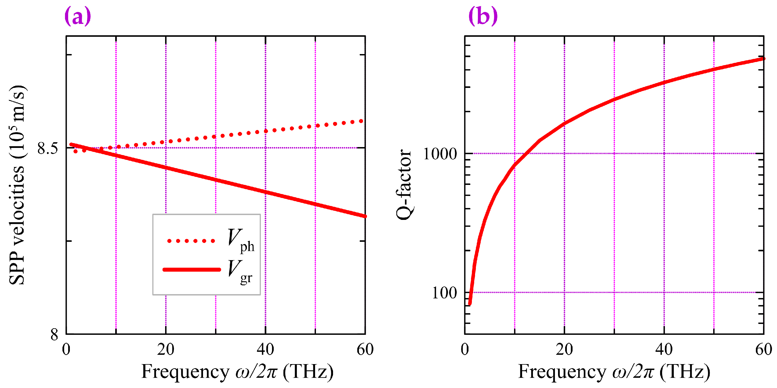
Figure 2a shows the frequency dependencies of the group
and phase
velocities for the fundamental “interlayer” SPP mode. In the presented frequency range, the group velocity
is a positive, slightly varying, almost linear function on a frequency. The phase velocity
takes the values of about 8.5 × 10
5 m/s, which provides an effective refractive index (i.e., the deceleration of SPPs
, where
c is the speed of light in vacuum) of approximately 350. Such a strong deceleration allows an SPP to interact with a drift current flowing through the CNT possessing a charge carrier velocity
(0.5–1) × 10
6 m/s [
13,
14]. As follows from
Figure 2b, the Q-factor of the fundamental interlayer SPP mode, defined as
, reaches significantly high values of ~10
2–10
3.
A specific feature of the obtained “interlayer” modes is the presence of a longitudinal component of the electric field
. We have found that the SPP “longitudinal” parameter [
41] averaged over the CNT cross section
(where
is the modulus of the electric field strength of the SPPs) is about 0.6 at frequencies of several THz, making the SPP interaction with the drift current efficient.
Thus, a DWCNT is a promising candidate for application in CNT-based devices employing the plasmon amplification by the drift current. The theoretical prerequisites for their operation are set out in Refs. [
24,
26,
27,
41].
4. Two-Beam Scheme of Super-Slow SPPs Excitation in the Array of DWCNTs
The mechanism of slow SPP generation in the THz and far-IR ranges by laser irradiation of the ordered CNT arrays has been considered in Ref. [
22]. Two schemes for the implementation of this process have been proposed. In the first scheme, self-decay (like parametric three-photon interaction in a periodic structure) of the initial laser wave occurs in a diffracted wave and the SPPs on the surface of the CNTs. The slow SPPs are excited in the CNT array due to the interaction of the incident narrow-band laser radiation and the diffracted waves with the periodically arranged CNTs. In the second case, two laser sources with slightly different frequencies excite the SPPs in the CNTs, and the slow SPP is generated at a difference frequency. The second scheme to be considered in this work is technically more complicated but does not require a strict periodicity of parallel CNTs in array.
Let us consider a two-dimensional ordered array of identical DWCNTs of external radius
a and length
L, located parallel to each other by the same distance
d (
Figure 3). Two laser beams with close frequencies
,
(
) and with wave numbers
are incident on this structure at angles
and
to the axis
x (perpendicular to the nanotube axes). When the conditions of phase-matching are met, the SPP generation occurs at the difference frequency
. The following parameters are used for the calculations: the first beam corresponds to the second harmonic of an erbium-doped fiber laser operating at
~ 1.55 µm; and the frequency
of the second beam is tunable over the range sufficient to generate the SPP at the difference frequency
of several THz.
In the projection onto the
z-axis (
Figure 3), the phase-matching condition for two incident laser beams is written as
where
is the wave number of the SPP excited in CNTs. The plasmon frequency in Equation (4) is up-limited by
, which is the solution of the equation
In the range of frequencies, where
is approximated by a linear dependence with a constant phase velocity
,
is found using Equation (5) as
Therefore, the highest is achieved when the first beam is directed along the CNTs in the array ().
For the numerical analysis of Equation (4), we use the characteristics of the fundamental “interlayer” SPP mode. So, we consider the SPPs with a constant phase velocity of
8.5·10
5 m/s. This gives the maximum frequency of the excited SPP
. For incident radiation with a wavelength of 0.775 µm and angle of incidence
, we get from Equation (6)
= 2.19 THz.
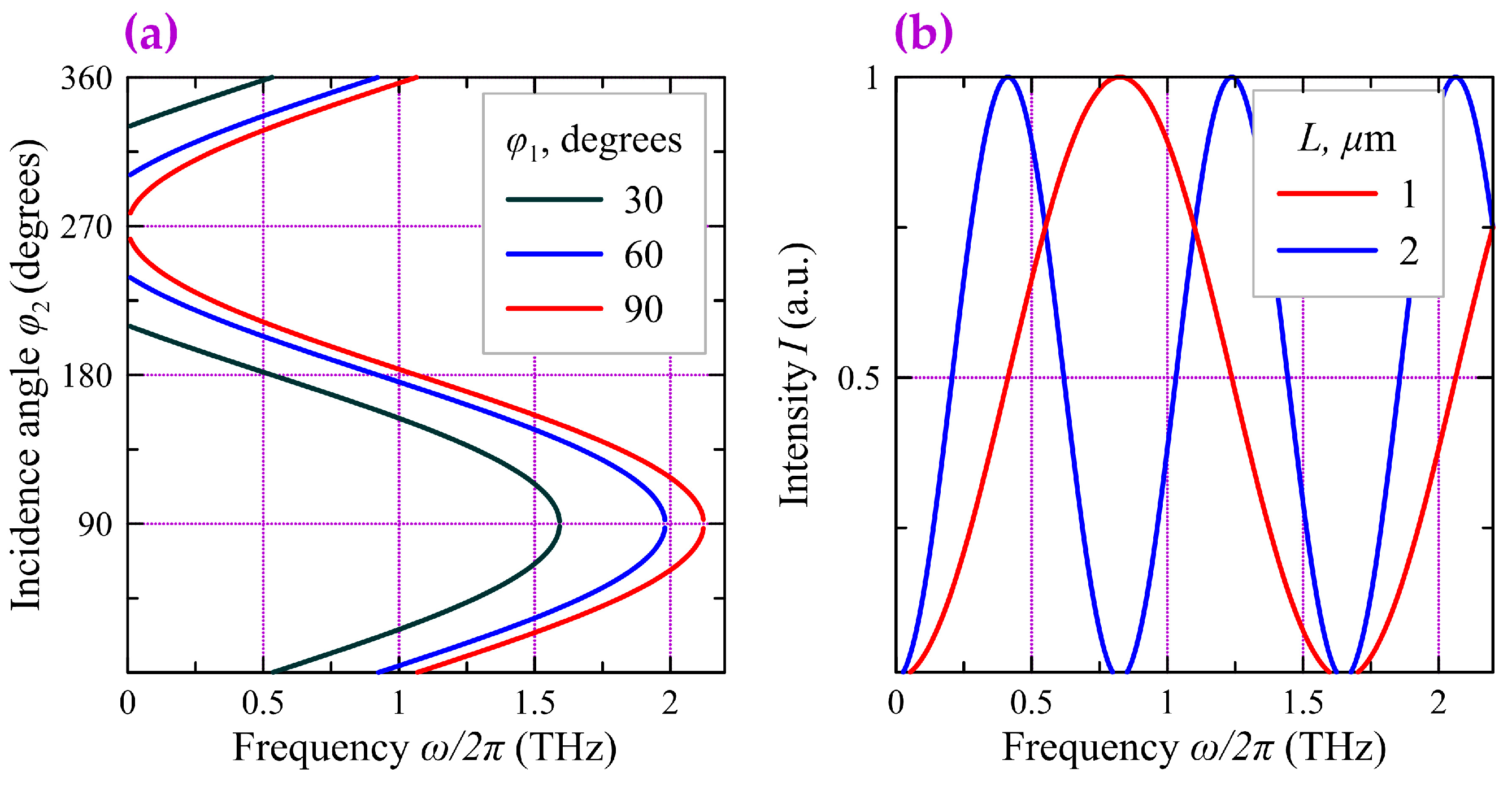
Figure 4a shows the angle of incidence of the second beam
versus frequency
of the SPPs excited in the CNT array for three values of angle
. One can see that for each frequency
in the range
there are two directions of the second beam propagation, which are symmetrically oriented with respect to the
z-axis.
5. Dispersion Relation for SPPs in the DWCNTs Taking into Account Drift Current
Let us assume that a constant potential difference is applied to the ends of the DWCNTs. The SPPs generated by laser radiation interact with the drift current flowing through the tubes. For slow SPPs, when the phase velocity of the SPP is close to the drift velocity of the current carriers
, this interaction can lead to the amplification of the SPP due to energy transfer from the drift current. Two different approaches are known for describing the interaction of slow SPPs with DC current and calculating the energy transfer between an electromagnetic wave and electronic subsystem of a waveguide structure. Within the framework of the approach proposed in [
23,
25,
42,
43,
44,
45,
46], the problem was solved using the total conductivity of the system depending on the drift current. It was shown that the total conductivity depends on the direction and velocity of the charge carrier drift and, under certain conditions, SPP enhancement due to the DC current energy can take place. Another approach is based on the application of working principles of traveling wave tube amplifiers [
47] and considers the interaction of the modulated electric current with the SPP in a “cold” system, i.e., in the system without the electric current. The fundamentals of this approach are outlined in the papers regarding the considered problem [
24,
26,
27,
41]. This approach uses the following equations describing the interaction between the current and the electromagnetic wave in the waveguide obtained in a perturbative approach:
where
is the longitudinal component of the SPP electric field,
is the current intensity in a single nanotube in the absence of coupling to the SPPs,
is a tiny spatial variation of the current intensity,
(
),
is the reduced plasma frequency depending on the waveguide geometry (for the numerical calculations we take an estimation
from Ref. [
48]), and
e and
m are the charge and the mass of charge carriers in the nanotube. In Equation (7),
represents a coupling parameter between the SPPs and the drift current:
, where
is a power carried by an electromagnetic wave
and
is the permittivity of the vacuum.
Let us assume that the current and electric field change proportionally along the CNT to exp(−
iGz), where
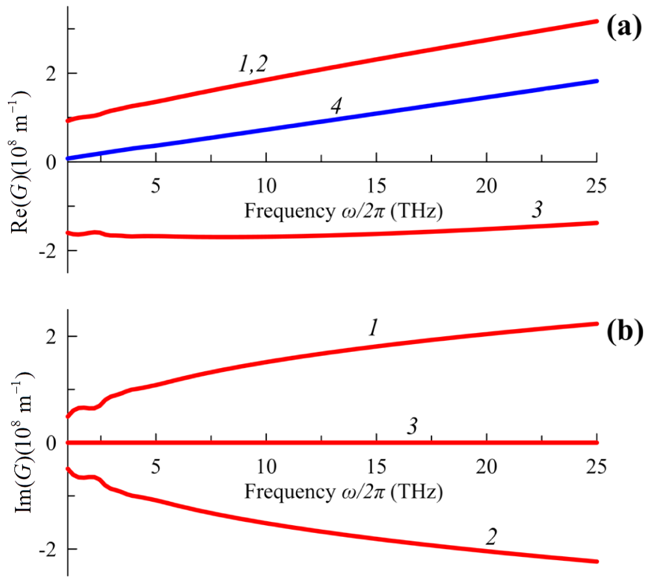
G is the wavenumber of the harmonic perturbation. The compatibility condition for the system of Equations (7) and (8) leads to the dispersion equation
where
Equation (9) is resolved by one real root (line 3 in
Figure 5) and two complex conjugated roots (lines 1 and 2 in
Figure 5). According to the calculations performed with the help of the COMSOL Multiphysics software, the increment
can get values of ~10
8 m
–1 that significantly exceed the values of losses (
~10
5 m
–1).
One should note that we do not explicitly obtain the conductivity of the nanotube taking into account the drift current as it has been done in Refs. [
25,
42], but we take into account the influence of the drift current on the SPP dispersion by solving the system of Equations (7) and (8). This approach, as well as the approaches used in [
42,
43], makes it possible to describe the instability (
Figure 5) in the presence of drift current as well as negative Landau damping.
The set of Equations (7) and (8) makes it possible to describe the interaction of the surface electromagnetic wave and electric current and obtain the dispersion relation for the SPPs in the DWCNT taking into account DC current.
6. CNT Array Radiation in the Far Zone
When a double-wavelength source or a comb generator with the pulse repetition rate
is used as an external laser source, the total current in a nanotube is the sum of the direct current
, due to the applied constant potential difference and the additional non-stationary current
from external laser radiation and SPPs:
Generally, the amplitude value of non-stationary current
depends on the magnitude of the direct current (see Equation (8)) and the intensity of the external laser radiation due to photocurrent generation [
49]. For the sake of simplicity in this work, the surface concentration of free charge carriers
ns is assumed to be a fixed value.
Laser-irradiated CNTs can be considered to be antennas emitting in the THz and far-IR radiation ranges. The theory of radiating antennas based on CNTs has been developed in [
3,
16,
50,
51]. The field radiated by a CNT antenna (as well as its other main parameters) is completely determined by the non-stationary current distribution
. It could be found by solving a self-consistent boundary value problem of electrodynamics using integral equations. In the far field region, the angular distribution of the CNT antenna radiation intensity
(
is the polar angle) at the distance
r can be expressed as [
51]
where
is the wavenumber of radiation from the nanoantenna in the free space and
Ohm is the characteristic vacuum impedance. For a given nanotube length
L, there is a discrete set of frequencies enabling the formation of standing waves resulting in the intensity given by Equation (11) reaching a maximum. According to Equation (11), the maximum condition has the form
, (
m = 0, 1, 2…), and one can see that the minimum length
L of a nanotube satisfying the geometric resonance is equal to the SPP wavelength.
Figure 4b shows the frequency dependences of the normalized intensity emitted by the CNT nanoantenna in the transverse direction (
) calculated for two fixed values of the length
L. It can be seen that to achieve the maximum efficiency of the nanoantenna, it is necessary to choose the SPP frequency. This task is reduced to choosing the radiation frequency of external laser sources. In addition, a corresponding adjustment of the incident angles of laser beams is required in accordance with
Figure 4a. Due to a strong SPP slowdown, the resonances should be observed at wavelengths that in free space can significantly (by two or three orders of magnitude) exceed the dimensions of the CNT antenna.
The total power emitted by a single CNT antenna can be estimated from the formula [
51]
where
is a non-negative periodic function of the length
L, the maximum value of which is close to 1. In this case, a set of
N coherent antennas increases the radiated power by
. Thus, in the case of a coherently excited array of CNTs, the total power emitted by the radiating surface can be
where
.
To estimate the maximum possible value of the total power emitted by the DWCNT array, we use the natural limitation on the amplitude of the non-stationary current due to the finite number of free current carriers in the carbon nanotube. In cases where the entire current in the DWCNT turns into a non-stationary one, its amplitude can be calculated by using the formula
For adopted parameters of the DWCNTs we get ≈ 0.4 mA and ≈ 350. Therefore, in accordance with Equation (13), for an array of N = 106 nanotubes, the total THz-radiation power emitted from the CNT arrays under conditions of their coherent excitation can reach values of order 102 W.
7. Discussion
The approach proposed in our work fundamentally differs from the widely known approach to THz radiation generation [
10,
52,
53,
54,
55,
56], based on irradiating a target with short laser pulses. In conventional laser pulse generation, “optical rectification” [
57] occurs, where a difference frequency close to zero is formed due to quadratic nonlinearity. This phenomenon arises when irradiating solid [
52], liquid crystal [
58], or gaseous [
54] media with femtosecond laser pulses. In the nonlinear medium, a kind of “frequency down-conversion” occurs, generating broadband THz pulses. In particular, several studies have considered CNT arrays as targets for laser pulses [
10,
53,
55,
56]. Typically, optical rectification in CNTs is also associated with quadratic nonlinearity. Using multiphoton processes for generating THz radiation entails inherently low energy efficiency.
In contrast, the efficiency of the generation mechanism proposed in our work is not directly related to energy conversion from external laser sources, which only serves to create distributed feedback. THz generation occurs due to the interaction of the SPP with the drift current, acting as a pump, and this interaction can proceed continuously. Our amplification scheme inherently lacks the limitations associated with the low energy efficiency of nonlinear processes. Moreover, since the proposed scheme utilizes the current pumping of the SPP, the total power of the generated radiation can be high due to the high conductivity of CNTs.
8. Conclusions
We have proposed a technique enabling the generation of THz radiation using an array of DWCNTs pumped by a direct electric current. The numerical simulations demonstrate the existence of slow SPP modes with a high Q-factor in DWCNTs. We have shown that the electric current can effectively amplify these slow SPP modes. To ensure this effect, the SPP phase velocity should be close to the drift current velocity (in the saturation regime, this velocity equals the Fermi velocity). However, this condition appears to be satisfied for a number of modes in the DWCNT. As a result, the simultaneous excitation of these modes disrupts the coherence of the radiation by the DWCNT array. To implement the coherent (phased) generation mode at a fixed wavelength, we propose to use coherent excitation of SPPs by a highly coherent laser source (two laser beams with slightly different frequencies in the near-IR range). With an array of DWCNTs implementing simultaneous optical irradiation and a drift current, the generation and amplification of SPPs occur at frequencies corresponding to the highest values of the Q-factor. The generated SPPs localized on the walls of the DWCNTs modulate the current flowing along the nanotubes in a coherent mode. In this case, the DWCNTs play the role of coherently emitting dipole antennas. As a result, this structure radiates as a single large dipole providing the total radiation power determined by the strength of the DC current flowing through the DWCNTs. The THz generator proposed in our study could potentially be used in fields demanding a compact source of coherent or at least narrowband THz radiation. These fields include biological and medical research, technical diagnostics, and 6G communication. Plasmonic generators, where the amplification of surface plasmon polaritons (SPPs) is achieved through current pumping, allow for a significantly greater SPP intensity and, consequently, a higher intensity of free THz waves.
Author Contributions
Conceptualization, I.O.Z., A.S.K. and S.G.M.; software, A.S.K.; investigation, S.A.A., A.S.K., S.G.M. and D.G.S.; resources, E.P.K., Y.P.S. and V.V.S.; writing—original draft preparation, S.A.A. and D.G.S.; writing—review and editing, A.A.F.; supervision, I.O.Z.; funding acquisition, A.A.F. All authors have read and agreed to the published version of the manuscript.
Funding
Section 1 and
Section 2 are supported by the Ministry of Science and Higher Education of the Russian Federation, grant number 075-15-2021-581 (the CNT conductivity model);
Section 3,
Section 4, and
Section 6 have been performed within the Russian Science Foundation grant, # 23-19-00880 (the two-beam excitation scheme, DWCNT array dispersion spectra, radiation in the far zone); and
Section 5 is supported by the Russian Science Foundation, grant # 23-79-30017 (the resonant electric-current-driven amplification of SPPs). A.A.F. is supported by the European Union’s Horizon 2020 research and innovation programme (Individual Fellowship, H2020-MSCA-IF-2020, #101028712).
Institutional Review Board Statement
Not applicable.
Data Availability Statement
The data presented in this study are available on request from the corresponding author. The data are not publicly available due to privacy.
Acknowledgments
The authors thank Ivars A. Rozhleys for the help with the simulation of spectral characteristics of SPPs.
Conflicts of Interest
The authors declare no conflict of interest.
References
- García-Vidal, F.J.; Pitarke, J.M.; Pendry, J.B. Effective Medium Theory of the Optical Properties of Aligned Carbon Nanotubes. Phys. Rev. Lett. 1997, 78, 4289. [Google Scholar] [CrossRef]
- Dai, L.; Patil, A.; Gong, X.; Guo, Z.; Liu, L.; Liu, Y.; Zhu, D. Aligned Nanotubes. ChemPhysChem 2003, 4, 1150–1169. [Google Scholar] [CrossRef]
- Hao, J.; Hanson, G.W. Electromagnetic Scattering from Finite-Length Metallic Carbon Nanotubes in the Lower IR Bands. Phys. Rev. B Condens. Matter Mater. Phys. 2006, 74, 035119. [Google Scholar] [CrossRef]
- Lidorikis, E.; Ferrari, A.C. Photonics with Multiwall Carbon Nanotube Arrays. ACS Nano 2009, 3, 1238–1248. [Google Scholar] [CrossRef]
- Roberts, J.A.; Yu, S.J.; Ho, P.H.; Schoeche, S.; Falk, A.L.; Fan, J.A. Tunable Hyperbolic Metamaterials Based on Self-Assembled Carbon Nanotubes. Nano Lett. 2019, 19, 3131–3137. [Google Scholar] [CrossRef]
- Batrakov, K.G.; Kibis, O.V.; Kuzhir, P.P.; da Costa, M.R.; Portnoi, M.E. Terahertz Processes in Carbon Nanotubes. J. Nanophotonics 2010, 4, 041665. [Google Scholar] [CrossRef]
- Sharma, S.; Vijay, A. Terahertz Generation via Laser Coupling to Anharmonic Carbon Nanotube Array. Phys. Plasmas 2018, 25, 023114. [Google Scholar] [CrossRef]
- Kumar, S.; Vij, S.; Kant, N.; Thakur, V. Resonant Terahertz Generation by the Interaction of Laser Beams with Magnetized Anharmonic Carbon Nanotube Array. Plasmonics 2022, 17, 381–388. [Google Scholar] [CrossRef]
- Kumar, S.; Kant, N.; Thakur, V. THz Generation by Self-Focused Gaussian Laser Beam in the Array of Anharmonic VA-CNTs. Opt. Quantum Electron. 2023, 55, 281. [Google Scholar] [CrossRef]
- Titova, L.V.; Pint, C.L.; Zhang, Q.; Hauge, R.H.; Kono, J.; Hegmann, F.A. Generation of Terahertz Radiation by Optical Excitation of Aligned Carbon Nanotubes. Nano Lett. 2015, 15, 3267–3272. [Google Scholar] [CrossRef]
- Lee, S.B.; Teo, K.B.K.; Robinson, L.A.W.; Teh, A.S.; Chhowalla, M.; Hasko, D.G.; Amaratunga, G.A.J.; Milne, W.I.; Ahmed, H. Characteristics of Multiwalled Carbon Nanotube Nanobridges Fabricated by Poly(Methylmethacrylate) Suspended Dispersion. J. Vac. Sci. Technol. B Microelectron. Nanometer Struct. Process. Meas. Phenom. 2002, 20, 2773. [Google Scholar] [CrossRef]
- Eletskii, A. V Transport Properties of Carbon Nanotubes. Phys.-Uspekhi 2009, 52, 209. [Google Scholar] [CrossRef]
- Perebeinos, V.; Tersoff, J.; Avouris, P. Electron-Phonon Interaction and Transport in Semiconducting Carbon Nanotubes. Phys. Rev. Lett. 2005, 94, 086802. [Google Scholar] [CrossRef] [PubMed]
- Liu, K.; Deslippe, J.; Xiao, F.; Capaz, R.B.; Hong, X.; Aloni, S.; Zettl, A.; Wang, W.; Bai, X.; Louie, S.G.; et al. An Atlas of Carbon Nanotube Optical Transitions. Nat. Nanotechnol. 2012, 7, 325–329. [Google Scholar] [CrossRef] [PubMed]
- Slepyan, G.Y.; Maksimenko, S.A.; Lakhtakia, A.; Yevtushenko, O.; Gusakov, A.V. Electrodynamics of Carbon Nanotubes: Dynamic Conductivity, Impedance Boundary Conditions, and Surface Wave Propagation. Phys. Rev. B 1999, 60, 17136. [Google Scholar] [CrossRef]
- Shuba, M.V.; Slepyan, G.Y.; Maksimenko, S.A.; Thomsen, C.; Lakhtakia, A. Theory of Multiwall Carbon Nanotubes as Waveguides and Antennas in the Infrared and the Visible Regimes. Phys. Rev. B Condens. Matter Mater. Phys. 2009, 79, 155403. [Google Scholar] [CrossRef]
- Martín-Moreno, L.; De Abajo, F.J.G.; García-Vidal, F.J. Ultraefficient Coupling of a Quantum Emitter to the Tunable Guided Plasmons of a Carbon Nanotube. Phys. Rev. Lett. 2015, 115, 173601. [Google Scholar] [CrossRef] [PubMed]
- Kadochkin, A.S.; Moiseev, S.G.; Svetukhin, V.V.; Saurov, A.N.; Zolotovskii, I.O. Excitation of Ultraslow High-q Surface Plasmon Polariton Modes in Dense Arrays of Double-Walled Carbon Nanotubes. Ann. Phys. 2022, 534, 2100438. [Google Scholar] [CrossRef]
- Moradi, A. Surface Plasmon-Polariton Modes of Metallic Single-Walled Carbon Nanotubes. Photonics Nanostruct. 2013, 11, 85–88. [Google Scholar] [CrossRef]
- Kumar, S.; Vij, S.; Kant, N.; Mehta, A.; Thakur, V. Resonant Terahertz Generation from Laser Filaments in the Presence of Static Electric Field in a Magnetized Collisional Plasma. Eur. Phys. J. Plus 2021, 136, 148. [Google Scholar] [CrossRef]
- Vij, S.; Kant, N.; Thakur, V. Resonant Enhancement of THz Radiation Through Vertically Aligned Carbon Nanotubes Array by Applying Wiggler Magnetic Field. Plasmonics 2019, 14, 1051–1056. [Google Scholar] [CrossRef]
- Afanas’ev, S.A.; Zolotovskii, I.O.; Kadochkin, A.S.; Moiseev, S.G.; Svetukhin, V.V.; Pavlov, A.A. Continuous-Wave Laser Generation of THz Slow Surface Plasmons in an Array of Single-Walled Carbon Nanotubes. Quantum Electron. 2018, 48, 849–853. [Google Scholar] [CrossRef]
- Svintsov, D.A.; Arsenin, A.V.; Fedyanin, D.Y. Full Loss Compensation in Hybrid Plasmonic Waveguides under Electrical Pumping. Opt. Express 2015, 23, 19358. [Google Scholar] [CrossRef]
- Moiseev, S.G.; Dadoenkova, Y.S.; Kadochkin, A.S.; Fotiadi, A.A.; Svetukhin, V.V.; Zolotovskii, I.O. Generation of Slow Surface Plasmon Polaritons in a Complex Waveguide Structure with Electric Current Pump. Ann. Phys. 2018, 530, 1800197. [Google Scholar] [CrossRef]
- Morgado, T.A.; Silveirinha, M.G. Drift-Induced Unidirectional Graphene Plasmons. ACS Photonics 2018, 5, 4253–4258. [Google Scholar] [CrossRef]
- Kadochkin, A.S.; Moiseev, S.; Dadoenkova, Y.S.; Bentivegna, F.; Svetukhin, V.; Zolotovsky, I.O. Resonant Amplification of Surface Plasmon Polaritons with an Electric Current in a Single-Walled Carbon Nanotube Lying on a Spatially Modulated Substrate. J. Opt. 2020, 22, 125002. [Google Scholar] [CrossRef]
- Kadochkin, A.S.; Moiseev, S.G.; Dadoenkova, Y.S.; Svetukhin, V.V.; Zolotovskii, I.O. Surface Plasmon Polariton Amplification in a Single-Walled Carbon Nanotube. Opt. Express 2017, 25, 27165. [Google Scholar] [CrossRef]
- Oraevsky, A.N. Whispering-Gallery Waves. Quantum Electron. 2002, 32, 377–400. [Google Scholar] [CrossRef]
- Lü, W.; Dong, J.; Li, Z.Y. Optical Properties of Aligned Carbon Nanotube Systems Studied by the Effective-Medium Approximation Method. Phys. Rev. B 2000, 63, 033401. [Google Scholar] [CrossRef]
- Bao, H.; Ruan, X.; Fisher, T.S.; Li, W.Z.; Xie, S.S.; Qian, L.X.; Chang, B.H.; Zou, B.S.; Zhou, W.Y.; Zhao, R.A.; et al. Optical Properties of Ordered Vertical Arrays of Multi-Walled Carbon Nanotubes from FDTD Simulations. Opt. Express 2010, 18, 6347–6359. [Google Scholar] [CrossRef]
- Furuta, H.; Kawaharamura, T.; Furuta, M.; Kawabata, K.; Hirao, T.; Komukai, T.; Yoshihara, K.; Shimomoto, Y.; Oguchi, T. Crystal Structure Analysis of Multiwalled Carbon Nanotube Forests by Newly Developed Cross-Sectional X-Ray Diffraction Measurement. Appl. Phys. Express 2010, 3, 105101. [Google Scholar] [CrossRef]
- Xiang, R.; Inoue, T.; Zheng, Y.; Kumamoto, A.; Qian, Y.; Sato, Y.; Liu, M.; Tang, D.; Gokhale, D.; Guo, J.; et al. One-Dimensional van Der Waals Heterostructures. Science 2020, 367, 537–542. [Google Scholar] [CrossRef] [PubMed]
- De Abajo, F.J.G. Graphene Plasmonics: Challenges and Opportunities. ACS Photonics 2014, 1, 133–152. [Google Scholar] [CrossRef]
- Bourlon, B.; Miko, C.; Forró, L.; Glattli, D.C.; Bachtold, A. Determination of the Intershell Conductance in Multiwalled Carbon Nanotubes. Phys. Rev. Lett. 2004, 93, 176806. [Google Scholar] [CrossRef] [PubMed]
- Falkovsky, L.A. Optical Properties of Graphene and IV–VI Semiconductors. Uspekhi Fiz. Nauk. 2008, 178, 923. [Google Scholar] [CrossRef]
- Yu, P.; Fesenko, V.I.; Tuz, V.R. Dispersion Features of Complex Waves in a Graphene-Coated Semiconductor Nanowire. Nanophotonics 2018, 7, 925–934. [Google Scholar] [CrossRef]
- Falkovsky, L.A.; Pershoguba, S.S. Optical Far-Infrared Properties of a Graphene Monolayer and Multilayer. Phys. Rev. B Condens. Matter Mater. Phys. 2007, 76, 153410. [Google Scholar] [CrossRef]
- Nikitin, A.Y.; Guinea, F.; García-Vidal, F.J.; Martín-Moreno, L. Edge and Waveguide Terahertz Surface Plasmon Modes in Graphene Microribbons. Phys. Rev. B Condens. Matter Mater. Phys. 2011, 84, 161407. [Google Scholar] [CrossRef]
- Hajaj, E.M.; Shtempluk, O.; Kochetkov, V.; Razin, A.; Yaish, Y.E. Chemical Potential of Inhomogeneous Single-Layer Graphene. Phys. Rev. B Condens. Matter Mater. Phys. 2013, 88, 045128. [Google Scholar] [CrossRef]
- Fateev, D.V.; Popov, V.V. Hydrodynamic Terahertz Plasmons and Electron Sound in Graphene with Spatial Dispersion. Semiconductors 2020, 54, 941–945. [Google Scholar] [CrossRef]
- Dadoenkova, Y.S.; Moiseev, S.G.; Abramov, A.S.; Kadochkin, A.S.; Fotiadi, A.A.; Zolotovskii, I.O. Surface Plasmon Polariton Amplification in Semiconductor-Graphene-Dielectric Structure. Ann. Phys. 2017, 529, 1700037. [Google Scholar] [CrossRef]
- Morgado, T.A.; Silveirinha, M.G. Negative Landau Damping in Bilayer Graphene. Phys. Rev. Lett. 2017, 119, 133901. [Google Scholar] [CrossRef]
- Svintsov, D. Emission of Plasmons by Drifting Dirac Electrons: A Hallmark of Hydrodynamic Transport. Phys. Rev. B 2019, 100, 195428. [Google Scholar] [CrossRef]
- Sabbaghi, M.; Lee, H.W.; Stauber, T.; Kim, K.S. Drift-Induced Modifications to the Dynamical Polarization of Graphene. Phys. Rev. B Condens. Matter Mater. Phys. 2015, 92, 195429. [Google Scholar] [CrossRef]
- Van Duppen, B.; Tomadin, A.; Grigorenko, A.N.; Polini, M. Current-Induced Birefringent Absorption and Non-Reciprocal Plasmons in Graphene. 2d Mater. 2016, 3, 015011. [Google Scholar] [CrossRef]
- Bliokh, K.Y.; Rodríguez-Fortuño, F.J.; Bekshaev, A.Y.; Nori, F.; Kivshar, Y.S. Electric-Current-Induced Unidirectional Propagation of Surface Plasmon-Polaritons. Opt. Lett. 2018, 43, 963–966. [Google Scholar] [CrossRef]
- Tsimring, S.E. Electron Beams and Microwave Vacuum Electronics; Wiley-Interscience: Hoboken, NJ, USA, 2006; ISBN 0470048166. [Google Scholar]
- Branch, G.M.; Mihran, T.G. Plasma Frequency Reduction Factors in Electron Beams. IRE Trans. Electron Devices 1955, 2, 3–11. [Google Scholar] [CrossRef]
- Barkelid, M.; Zwiller, V. Photocurrent Generation in Semiconducting and Metallic Carbon Nanotubes. Nat. Photonics 2013, 8, 47–51. [Google Scholar] [CrossRef]
- Hanson, G.W. Fundamental Transmitting Properties of Carbon Nanotube Antennas. IEEE Trans. Antennas Propag. 2005, 53, 3426–3435. [Google Scholar] [CrossRef]
- Burke, P.J.; Li, S.; Yu, Z. Quantitative Theory of Nanowire and Nanotube Antenna Performance. IEEE Trans. Nanotechnol. 2006, 5, 314–334. [Google Scholar] [CrossRef]
- Fülöp, J.A.; Pálfalvi, L.; Klingebiel, S.; Almási, G.; Krausz, F.; Karsch, S.; Hebling, J. Generation of Sub-MJ Terahertz Pulses by Optical Rectification. Opt. Lett. 2012, 37, 557. [Google Scholar] [CrossRef]
- Huang, S.; Li, W.; Zhu, L.; He, M.; Yao, Z.; Zhou, Y.; Xu, X.; Ren, Z.; Bai, J. Terahertz Emission from Vertically Aligned Multi-Wall Carbon Nanotubes and Their Composites by Optical Excitation. Carbon. N. Y. 2018, 132, 335–342. [Google Scholar] [CrossRef]
- Wang, W.-M.; Sheng, Z.-M.; Wu, H.-C.; Chen, M.; Li, C.; Zhang, J.; Mima, K. Strong Terahertz Pulse Generation by Chirped Laser Pulses in Tenuous Gases. Opt. Express 2008, 16, 16999. [Google Scholar] [CrossRef] [PubMed]
- Hassani, M.; Jahangiri, F. Tuning Single-Walled Aligned Carbon Nanotubes for Optimal Terahertz Pulse Generation through Optical Rectification of Ultrashort Laser Pulses. Opt. Express 2021, 29, 38359. [Google Scholar] [CrossRef]
- Parashar, J.; Sharma, H. Optical Rectification in a Carbon Nanotube Array and Terahertz Radiation Generation. Phys. E Low-Dimens. Syst. Nanostruct. 2012, 44, 2069–2071. [Google Scholar] [CrossRef]
- Bass, M.; Franken, P.A.; Ward, J.F.; Weinreich, G. Optical Rectification. Phys. Rev. Lett. 1962, 9, 446–448. [Google Scholar] [CrossRef]
- Wang, L.; Qiu, H.; Jin, P.; Ge, S.; Shen, Z.; Hu, W.; Li, B.; Nakajima, M.; Jin, B.; Lu, Y. THz Generation by Optical Rectification of Femtosecond Laser Pulses in a Liquid Crystal. J. Opt. Soc. Am. B 2022, 39, A89. [Google Scholar] [CrossRef]
| Disclaimer/Publisher’s Note: The statements, opinions and data contained in all publications are solely those of the individual author(s) and contributor(s) and not of MDPI and/or the editor(s). MDPI and/or the editor(s) disclaim responsibility for any injury to people or property resulting from any ideas, methods, instructions or products referred to in the content. |
© 2023 by the authors. Licensee MDPI, Basel, Switzerland. This article is an open access article distributed under the terms and conditions of the Creative Commons Attribution (CC BY) license (https://creativecommons.org/licenses/by/4.0/).

 ,
, 