1. Introduction
Photonic band gap (PBG) materials, like photonic crystals (PhC) [
1,
2], in combination with plasmonic metallic nanoparticles promise to be highly attractive for efficient use of incident light [
3]. A major field in which these effects can be exploited is the study on PhC-based plasmonic photocatalysis [
4,
5,
6,
7]. This type of experiment has been conducted on various PBG and PhC nanoarchitectures and Au nanoparticles were one of the most frequently used “dopants” as reported in some recent reviews and the references therein [
4,
8,
9,
10]. The most relevant parameters of the produced photonic nanoarchitectures, like the solid constituent of the PhC or PBG materials (SiO
2, TiO
2, various polymers, etc.), their characteristic periodicity (from 200 nm to 1000 nm), and the method used for the introduction of the Au nanoparticles (infiltration, co-deposition, deposition, etc.) varied widely [
8]. Therefore, the comparison of the effects reported in these experiments is not straightforward [
3].
Another issue worth pointing out is the fact that the production of opal and inverse opal-type PhCs by self-assembly may be expensive, time consuming, requires a skilled workforce, and may have an adverse environmental impact, too [
11,
12]. Therefore, we used photonic nanoarchitectures of biologic origin, which are responsible for the blue structural color of male
Polyommatus icarus butterflies [
13,
14]. As we reported recently, by breeding these butterflies under controlled conditions in the laboratory, a much better reproducibility of the spectral properties was achieved as compared to the wild-caught exemplars [
15]. A single female may lay 600–700 eggs, due to the absence of the predators, and thanks to the carefully controlled conditions, most of the larvae reach the imaginal state. This production process of PBG materials, based on the use of herbivorous insects to bio-synthesize the chitin-based photonic nanoarchitectures, may be advantageous under several aspects: it is cheap, does not necessitate a highly skilled workforce, and has no adverse environmental impact. It is worth pointing out that such insect-based technologies, like the production of natural silk by the domesticated
Bombyx morii moth [
16] and honey production by the honey bee
Apis mellifera [
17], have been used for several millennia.
We used three different methods of depositing the nanoscale Au into/onto the butterfly wing scales: (i) a new procedure developed for the in situ synthesis of the Au nanoparticles inside the pores of the photonic nanoarchitecture of the wing scales by photoreduction of HAuCl4 solution containing sodium citrate as capping agent; (ii) deposition of Au nanoparticles formed in the bulk liquid phase of the (i) preparation, by drop-drying onto the pristine butterfly wing; and (iii) physical vapor deposition (PVD) to coat the wings with 5 or 15 nm thin layers of Au. Both liquid-based depositions of Au nanoparticles were carried out at two different Au concentrations. We were interested in comparing the optical and structural properties of the samples that were all based on similar photonic nanoarchitectures of biologic origin.
A major advantage of particle growth inside the butterfly wings, as compared to the Au nanoparticle deposition from sols produced by the classical Turkevich method [
18,
19] by drop-drying, is that in the former case, the liquid medium can be evaporated without the aggregation of the Au nanoparticles [
20].
The samples were characterized by UV–vis spectroscopy, optical and electron microscopy, and X-ray diffraction (XRD). We found that the introduction of both types of the Au nanoparticles in the butterfly wings induced a redshift of the reflectance maxima of the pristine wings, while the samples with thin Au overlayers produced by PVD exhibited a “grey filter”-type behavior, which did not produce the shift of reflectance maxima, only the decrease in their amplitude.
2. Materials and Methods
2.1. Butterfly Wings
We used the dorsal, homogenously blue wing surfaces of the male
P. icarus butterflies. The specimens were produced in our laboratory by breeding the butterflies under controlled conditions [
15]. The wings used were detached from the body of the dried butterfly, were carefully mounted on glass slides cut from microscope slides using poly(methyl methacrylate) (PMMA) photoresist as an adhesive, in such a way to avoid the infiltration of the PMMA into the cover scales containing the photonic nanoarchitecture. Following the mounting, all wings were pretreated in ethanol absolute by soaking them overnight followed by washing with ethanol and drying. After the pretreatment, the wings were characterized by UV–vis reflectance spectroscopy.
2.2. Au Nanoparticle Growth Inside the Nanopores of the Photonic Nanoarchitecture
The pretreated wings on glass slides were placed in a 5 cm × 5 cm × 1 cm glass cuvette (Hellma Materials Sweden AB, Trollhättan, Sweden) and the following ingredients for nanoparticle preparation were added for the single dose sample: 6000 µL of ultrapure water (produced by Adrona water purification system), 698 µL of 10 mM sodium citrate (trisodium citrate dihydrate, 98%, Reanal Laboratory Chemicals Ltd., Budapest, Hungary), and 269 µL of 5.2 mM HAuCl
4 (gold(III) chloride trihydrate, 99.9%, Sigma-Aldrich, St. Louis, MO, USA). The solution was kept at constant 50 °C and continuously mixed with a magnetic stirrer. Gold nanoparticles were formed while illuminating the cuvette for 15 min using a small area solar simulator (ORIEL LCS-100, Newport Corporation, Irvine, CA, USA). The transition of the solution upon illumination from colorless (very pale yellow) to light red is clearly visible with the naked eye [
21,
22]. For the four-dose sample, the addition of 269 µL of 5.2 mM HAuCl
4 and 15 min illumination was repeated three more times to increase the particle size and quantity. The solution darkened perceptibly at each step. After the completion of the growth, the bulk liquid phase (the formed Au sol) was removed from the wing samples, which were then soaked overnight in ultrapure water to remove any water-soluble residue left over from the wing nanoarchitecture. The extinction of the Au sol produced was measured in a 1 cm light path quartz cuvette using a modular Avantes spectrophotometer system.
2.3. Samples Prepared by Drop-Drying the Au Sol onto Wings
After the completion of the in situ growth cycles of Au nanoparticles inside the photonic nanoarchitecture of the wing scales, the resulting Au sol taken from the bulk liquid volume was used to prepare samples on clean butterfly wings by drop-drying. PDMS rings (Silicone sealing ring f. GL threads, without PTFE washer, 16 × 8 mm, DWK Life Sciences, Mainz, Germany) were pressed mechanically onto the surface of the glass-mounted wing to avoid the leakage of the sol. We used 120 µL of the sol introduced in the 8 mm diameter central opening of the ring, measured with Biohit Proline (Biohit Healthcare Ltd., Helsinki, Finland) automatic pipette. The samples were left to dry overnight, then the PDMS rings were removed, and the samples were characterized.
After the first spectral characterization, the drop-dried samples were subjected to 70 h soaking in ultrapure water to remove the water-soluble components of the original sols. This was followed by the second spectral characterization.
2.4. Physical Vapor Deposition
Butterfly wings, mounted onto microscope cover slides, were applied as substrates during physical vapor deposition processes. Before loading the samples into the evaporation chamber, the individual samples were attached close to each other to a common sample holder to ensure the thickness homogeneity of the evaporated layer. Gold wire of 99.99% purity was evaporated using a resistively heated tungsten boat source. The evaporation rate was between 0.1–0.15 nm/s, at a pressure of 1 × 10⁻⁶ Torr during deposition. The film thickness was controlled by a vibrating quartz crystal. The deposited gold thicknesses were 5 and 15 nm for the two groups of the samples, respectively, according to the in situ measurement. Sample temperatures did not exceed the 40 °C limit during the evaporation process.
2.5. Cross-Sectional SEM Characterization of Wing Scales
Small pieces of butterfly wings were cut under liquid nitrogen and mounted on SEM stubs with conductive tape, and images were taken at the cut surface using a Thermo Fisher Scientific Scios 2 DualBeam (Waltham, MA, USA) microscope.
2.6. TEM Characterization of the Au Nanoparticles
A few drops of Au sols from the in situ growth preparation were dried on carbon-coated copper TEM grids. The wing scales detached from the wing samples on which Au nanoparticles were grown in situ for four cycles with the addition of Au precursor were attached to bare TEM grids for imaging. TEM characterization was carried out using a Thermo Fischer Scientific THEMIS 200 (Waltham, MA, USA) objective spherical aberration-corrected transmission electron microscope operated at 200 kV, in STEM mode using bright field (BF) and in some cases high-angle annular dark field (HAADF) detectors. In BF conditions, the Au nanoparticles appear as dark dots on the light background of the chitin or carbon film substrate due primarily to intense scattering of the crystalline and relatively heavy Au particles. In HAADF conditions it is quite the opposite, and the Au nanoparticles appear as bright dots on the dark chitin matrix, because the image is generated from the inelastically scattered electrons, originating mostly from the heavy Au atoms.
2.7. UV–Vis Spectrophotometry
Reflectance spectroscopy measurements were conducted using an Avantes (Avantes BV, Apeldoorn, The Netherlands) modular fiber-optic system consisting of a high-sensitivity spectrophotometer (AvaSpec-HSC1024x58TEC-EVO), a stabilized deuterium-halogen light source (AvaLight-DH-S-BAL), an integrating sphere (AvaSphere-30-REFL), and a white diffuse tile (WS-2) as a reference. The integrating sphere was used to make sure that all the light reflected and scattered in the upper hemisphere by the butterfly wing was collected and analyzed.
2.8. Focus Stacking Optical Microscopy
Optical microscopy was conducted by the 100× objective (NA: 0.90) of a Nikon Eclipse LV150N device using extended depth of focus (EDF) mode, which resulted in high depth of field images of the significantly textured butterfly wing surfaces. The objective has a long working distance of 2.00 mm that does not necessitate oil immersion.
2.9. XRD Characterization of the Dried Au Sol Samples and the Au-Loaded Butterfly Wings
XRD measurements were carried out with a D8 Discover X-ray diffractometer (Bruker AXS, Karlsruhe, Germany) equipped with Göbel-mirror and scintillation detector using Cu Kα (λ = 1.5406 Å) radiation. The X-ray beam dimensions were 1 mm × 5 mm, the 2Θ step size was 0.02°, and the measuring speed 0.2°/min.
3. Results
The photonic nanoarchitecture producing the homogenous blue structural color of the wings of the male
P. icarus butterflies is well characterized in our earlier works [
13,
23]. Schematically, it can be presented as shown in
Figure 1. When PVD is used to coat the butterfly wing, the metallic particles follow a “line-of-sight” trajectory from the evaporation source to the target. As the target is kept at room temperature, the mobility of deposited material is negligible. Therefore, the Au layer is expected to be present primarily on the surface exposed towards the evaporation source as shown in
Figure 1a. The drop-drying is expected to deposit more material on the outer surface of the scale (
Figure 1b), while the in situ Au nanoparticle growth is also expected to take place inside the pores of the scales (
Figure 1c).
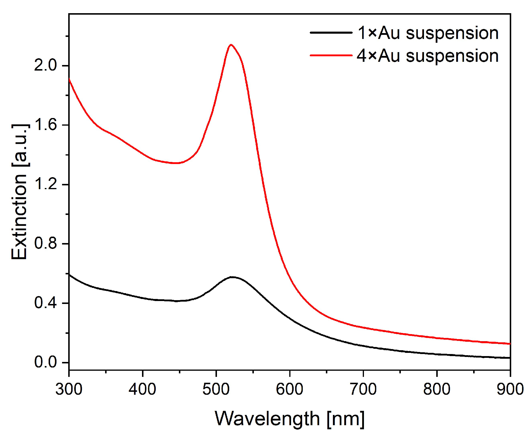
In
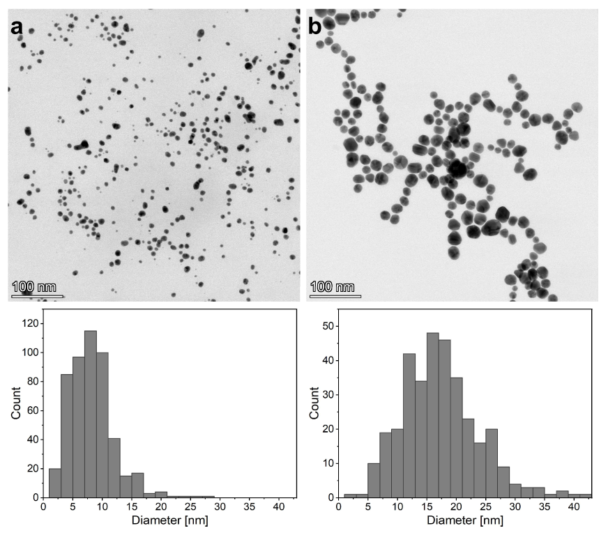
Figure 2, the UV–vis extinction spectra of the two Au nanoparticle sols from the bulk liquid volume surrounding the wings after the in situ particle growth preparations using one and four doses of Au precursor (1×Au and 4×Au), respectively, are shown. One may observe that the major difference is in the magnitude of the extinction when comparing the two spectra. A few nm shift in the peak position of the extinction curves is also present, but in accordance with nanoparticle size histograms in
Figure 3, the increase in modal diameter from 8 nm to 16 nm is not expected to produce a significant shift in the wavelength of the plasmonic resonance [
24,
25]. The spectra in
Figure 2 and the TEM images of
Figure 3, together with the particle diameter histograms, show that the major effects of the repeated addition of the same amount of Au precursor to the initial sodium citrate solution is the increment in the number of the Au nanoparticles present in the suspension and broadening of their size distribution.
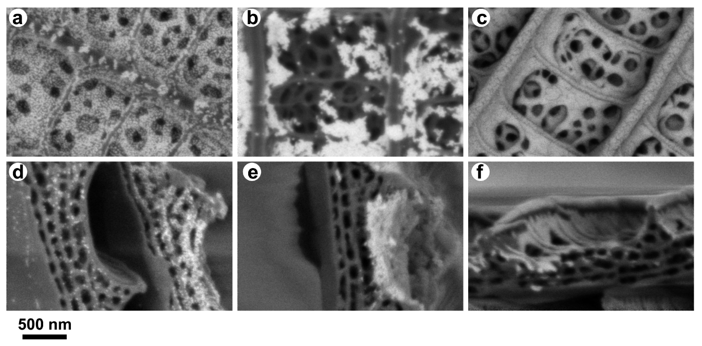
In
Figure 4, the SEM images of photonic nanoarchitectures, from top view and in cross-section, prepared using cryogenic cleavage from butterfly wing cover scales are shown after in situ particle growth (Gr), drop-drying (Dr), and PVD. The bright dots seen on the photonic nanoarchitecture correspond to the Au nanoparticles. The images were acquired using a backscattered detector. In this imaging mode, the Au appears as bright spots on the darker background of the chitin due to the atomic number contrast. One may observe that on the surface of the Gr sample, uniform distribution of individual Au nanoparticles can be observed and in the cross-sectional image, the deep penetration of the Au nanoparticles can be seen. On the Dr sample, the Au nanoparticles show strong clustering and aggregation with only moderate penetration into the volume of the scale. The PVD sample exhibits a continuous gold coating on the surface of the scale with negligible penetration into the volume of the scale. It is worth emphasizing that the SEM images show dried samples, so that the SEM images in
Figure 4a,d clearly show that even in the dried state of the Gr sample, the Au nanoparticles did not aggregate.
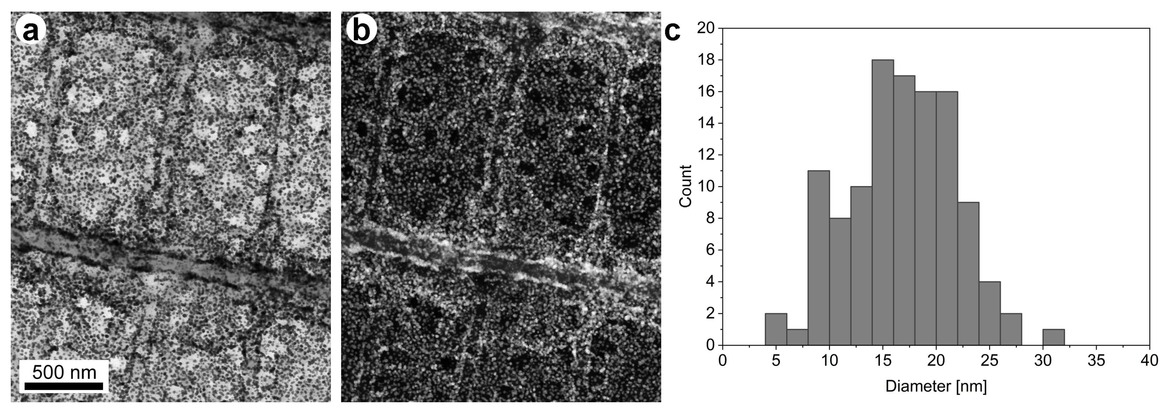
The lack of aggregation is further supported by the STEM BF and HAADF images in
Figure 5. The two images show the same region of a cover scale after in situ growth with four additions of Au precursor. In
Figure 5a, one can clearly see the individual dark Au nanoparticles, well separated from each other. In
Figure 5b, one can see that the bright Au nanoparticles are attached to the chitinous nanostructures building up the photonic nanoarchitecture of the butterfly scale. The STEM images are in full agreement with the SEM image in
Figure 4a. The histogram in
Figure 5c showing the size of the Au nanoparticles formed inside the chitinous photonic nanoarchitecture is in good agreement with the histogram showing the size of the Au nanoparticles found in the 4×Au sol (
Figure 3b).
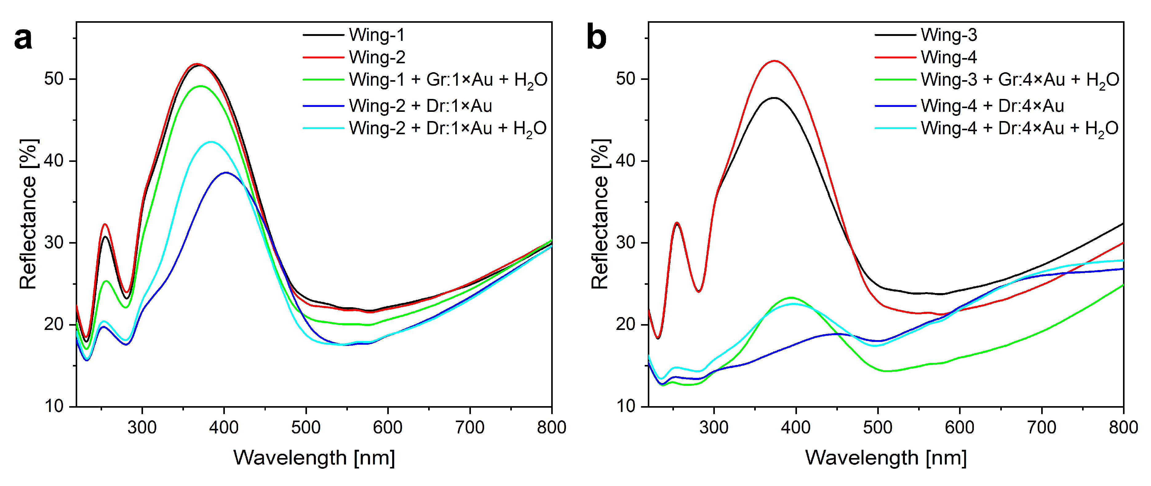
The reflectance of the wings before and after the in situ growth (Gr) and drop-drying (Dr), respectively, using the one single dose Au precursor (1×Au) are shown in
Figure 6a. One may remark that before the Au deposition, the wings had overlapping spectra, the Dr wing exhibited a larger redshift than the Gr wing and a more pronounced reduction in the amplitude of the reflectance maximum. After the 70 h soaking in water of the Dr wing, its reflectance maximum blue-shifted and some of the amplitude decrease was recovered, indicating that the water-soluble components of the Au sol were removed.
In
Figure 6b, a similar sequence of reflectance curves is shown as in
Figure 6a, the difference being that four doses of Au precursor (4×Au) were added during the growth of Au nanoparticles. The increase in the total amount of Au precursor used produced a larger redshift and a significant reduction in the amplitude of reflectance maxima both for the Gr and the Dr samples. Both effects are much stronger for the Dr sample. After the 70 h water soaking, these differences were eliminated and the spectra corresponding to the Gr and Dr samples overlap in the region of the reflectance maximum. This again shows that the initial differences between the Gr and the Dr samples originated mainly from the water-soluble components of the Au nanoparticle sols. On the other hand, the spectral difference of the Gr and Dr samples in the range of 450–800 nm persists even after the water soaking of the Dr sample. As no other components are present but Au nanoparticles and water-soluble substances (
Figure S1 in the Supplementary Materials), this difference must be associated with the different distribution of the Au nanoparticles in the Gr and the Dr samples. As this wavelength range can be associated with the coupled LSPR of the aggregated Au nanoparticles [
26,
27], the spectral differences are in good agreement with the SEM images in
Figure 4. While
Figure 4 is a local characterization, the reflectance spectra in
Figure 6b are averaged over a large area.
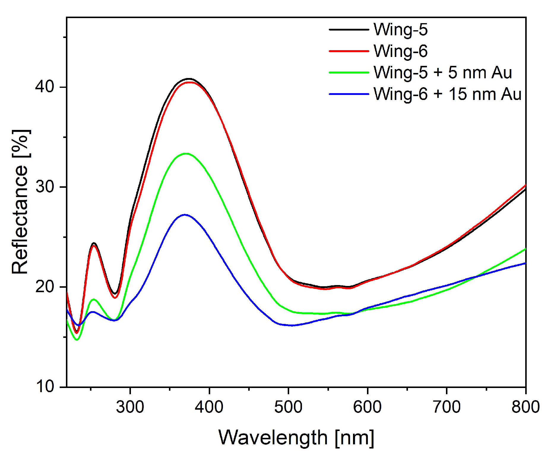
The spectra of the butterfly wings Au coated by PVD are shown in
Figure 7. The most significant difference as compared with the Gr and Dr samples is the absence of the shift in the position of the reflectance maximum. Before the Au coating, the wings had overlapping spectra, the deposition of 5 nm of Au reduced the amplitude of the reflectance peak by 7%, while the deposition of 15 nm of Au reduced it by 13%.
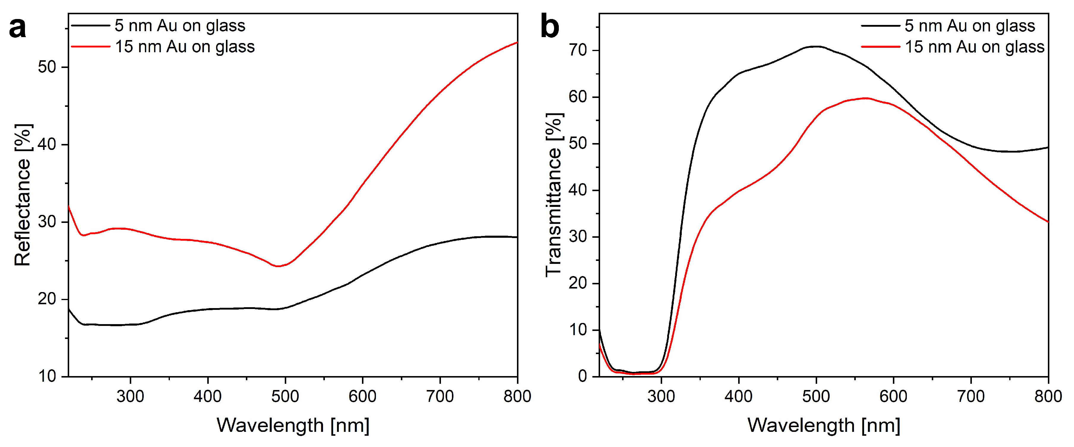
In
Figure 8, the transmittance and reflectance spectra of the Au films on glass slides are shown. The 5 nm and the 15 nm films have been deposited in the same experimental cycles as the corresponding butterfly wings. When examined by the naked eye, the 5 nm layer has a blue–gray color in reflected light, while the 15 nm layer has a weak golden color, in good agreement with the measured reflectance spectra (
Figure 8a). The transmittance spectra in
Figure 8b are affected by the glass absorption below 380 nm. The 5 nm Au layer has the same blue–gray aspect as in reflected light, while the 15 nm Au layer has a color shifted towards the yellow–orange region. None of the Au on glass spectra has any particular features in the range of 370–380 nm, where the reflectance maximum of the pristine butterfly wing is located.
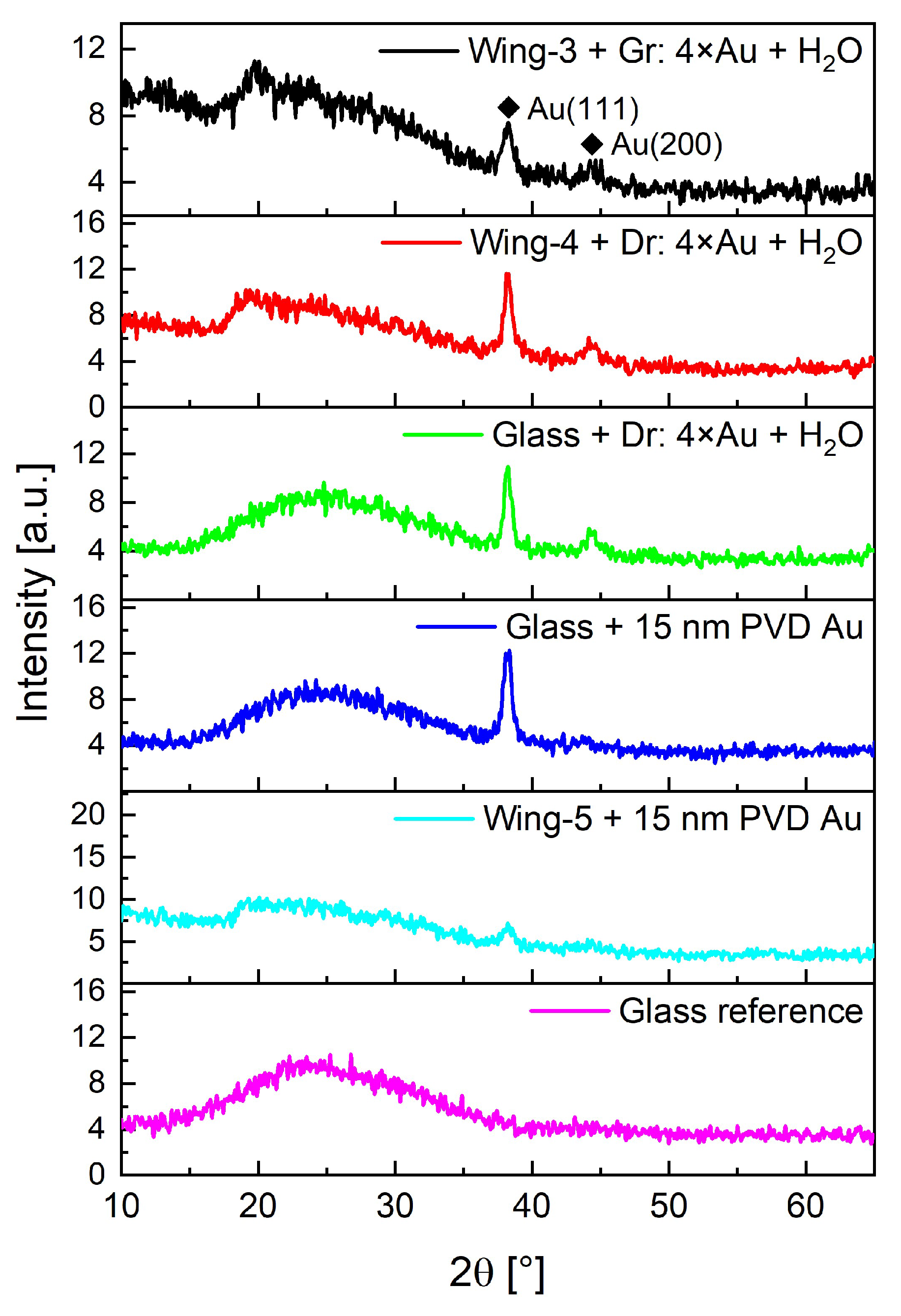
To identify the crystalline solids in the dried Au sol sample that was prepared with four doses of Au precursor, the sol was drop-dried on Si(100) surface and measured by X-ray diffraction analysis. As shown in
Figure S1, the lines of NaCl and of Au are clearly identified, and a line of the single crystalline Si substrate is present.
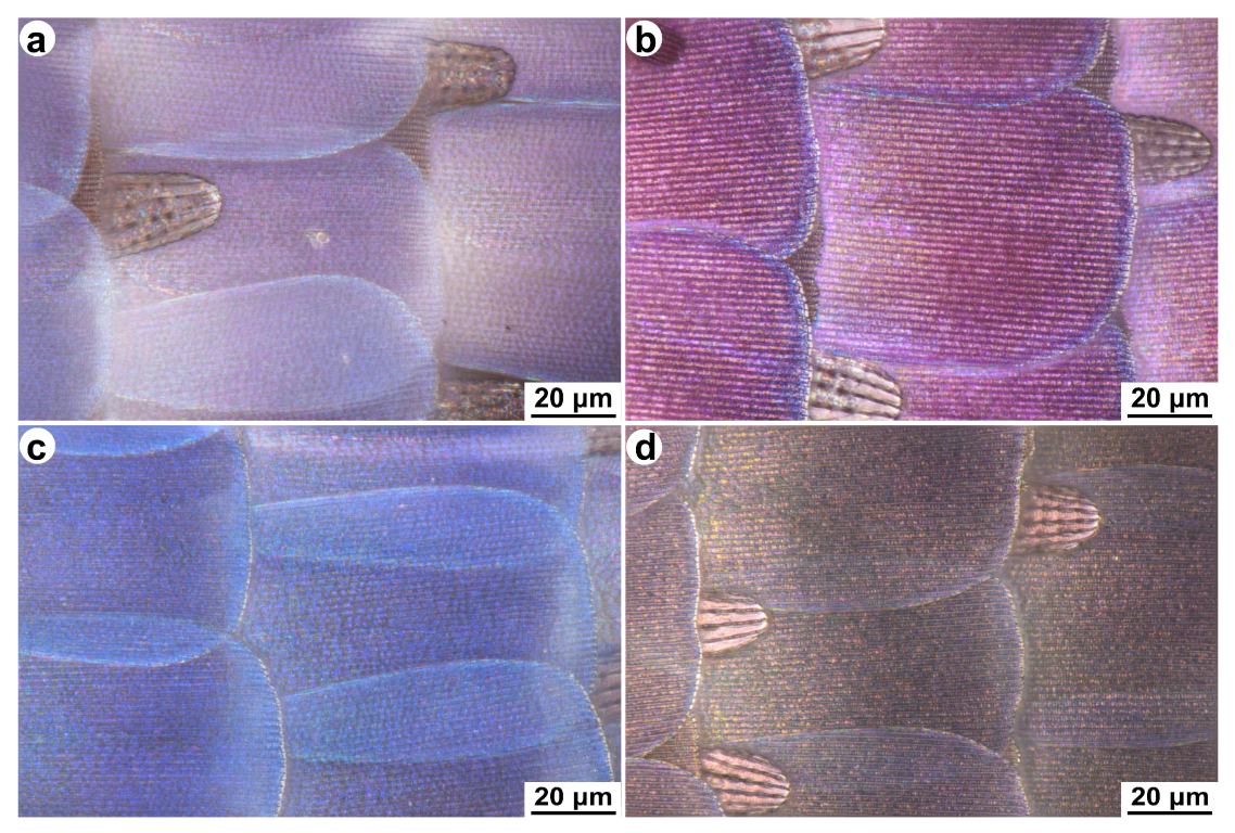
The wing samples prepared by in situ growth (Gr) after the removal of the water-soluble residues and the samples produced by PVD were examined by focus stacking microscopy. In
Figure 9, the micrographs of four samples are compared: (a) sample grown by a single dose of Au precursor; (b) sample grown by four doses of Au precursor; (c) sample with 5 nm of PVD Au; and (d) the sample with 15 nm of PVD Au. The color changes are consistent with the spectral data of
Figure 6 and
Figure 7.
XRD was used to characterize selected Au grown and drop-dried samples after the 70 h water soaking. The spectra are shown in
Figure 10. One can clearly see that no NaCl peaks are present, therefore, the removal of the water-soluble residues is successful. Furthermore, the magnitude of the Au lines (see PDF Nr. 4-0784) seems to indicate that in the Gr sample, the quantity of the Au is smaller than in the Dr sample. Comparing the XRD line of the Au deposited by PVD on the butterfly wings and glass—the samples were fabricated in the same experiment—one may conclude that distribution of the same amount of Au in the 3D photonic nanoarchitecture gives a weaker XRD peak than the Au deposited on flat glass.
4. Discussion
Instead of the well-known sodium citrate and HAuCl
4-based growth method [
22], in which an aqueous solution of tetrachloroauric acid is reduced at boiling temperature by addition of a small amount of sodium citrate solution, in our experiments, the Au nanoparticles were prepared by the intense illumination-induced reduction of an aqueous solution of tetrachloroauric acid and trisodium citrate kept under continuous stirring at 50 °C, at temperature where without photoinduction the reduction was negligible (as confirmed by reference dark test). A small area sun simulator is used for illumination, which is, to some extent, similar to the processes reported in [
26,
27,
28]. However, we did not use seeding, PEG, and acetone in our current work. For a recent review of the photochemical synthesis of Au nanoparticles see [
29]. Our main goal was to synthesize the Au nanoparticles in situ inside the nanopores of the chitin-based photonic nanoarchitecture responsible for the blue structural color of the dorsal wing surfaces of the male
P. icarus butterflies. The photoreduction method allows the introduction of the preparation solution into the nanopores of butterfly wings at low temperature without reaction, then after balancing the concentration in the whole system, a fast reduction and particle formation can also be started inside the pores by switching on the illumination. Furthermore, we were interested to compare the optical properties of these novel bio-hybrid photonic nanoarchitectures with similar hybrids but produced by drop-drying controlled amounts of Au sols onto the pristine butterfly wings, which were produced during the Gr preparation mainly in the bulk liquid volume outside of the scales’ pore system (Dr).
As shown by our SEM and STEM results (
Figure 4 and
Figure 5), both kinds of samples, Gr and Dr, have an advantage with respect to the colloidal Au samples produced by the classical Turkevich method [
20] and its derivatives [
21]: Au nanoparticles in the bio-hybrid nanoarchitectures can be dried, and even in dry state the Au particles preserved their dispersed state, especially in the Gr method, and the properties associated with the nanoscopic dimensions of the Au component. This is in contrast with the usual solution of colloidal gold produced by the citrate route, which cannot be redispersed after drying [
22]. The SEM micrographs in
Figure 4 show the differences in the distribution of the Au nanoparticles when using in situ growth (Gr) or drop-drying (Dr). In the case of the Gr sample, the top-view image shows uniform distribution, and the cross-sectional image shows deep penetration of the Au nanoparticles in the volume of the scales. The in-volume imaging, using STEM on single scales detached from the wing membrane of the Gr sample (
Figure 5), shows that even in the volume of the scale, the nanoparticles are well separated and have a similar distribution as that found in the free colloidal Au sol surrounding the butterfly wing. On the contrary, for the Dr sample, most of the Au sits on top of the photonic nanoarchitecture, and the top-view image shows non-uniform clustering. This is a less advantageous arrangement of the nanoparticles if some further use, like photocatalysis, is envisaged.
In
Figure 4c,f, the top-view and the cross-sectional micrographs are shown for the wing coated with 15 nm Au by PVD. The close to conformal coating of the top surface can be observed. Deviations from the conformal coating are produced when certain areas are shadowed by the nanoarchitecture itself.
The colloidal Au sols produced have characteristic LSPR bands in their UV–vis extinction spectra (
Figure 2) in agreement with data from the literature. The 1×Au spectrum in
Figure 2 has an extinction maximum at 523 nm, while the 4×Au spectrum has its maximum at 520 nm. As can be seen from the histograms in
Figure 3, the sol corresponding to one single dose of Au precursor (1×Au) has a narrower size distribution of Au nanoparticles as compared to the sol with four doses of Au precursor (4×Au). The modal Au nanoparticle diameters are 8 nm (1×Au) and 16 nm (4×Au). For the histogram in
Figure 5, the modal diameter value is 15 nm. In this size range, the extinction maximum for commercial, monodisperse Au nanoparticles is expected in the range of 515 to 520 nm [
26,
27], in good agreement with our data.
The Au nanoparticle modal diameters close to each other can be explained by the characteristics of the citrate method; when the citrate concentration with respect to the Au precursor concentration increases up to two, the particle size decreases, but exceeding two, the particle diameters exhibit very little dependence on the relative composition of the reactants [
22]. In our reaction conditions, the ratio of citrate to Au precursor molar concentration was 5 in case of 1×Au addition, while in the 4×Au addition (without additional citrate) this ratio decreased step by step until reaching 1.25.
The UV–vis reflectance spectra taken on the butterfly wings modified with Au nanoparticles grown in situ (Gr) or deposited by drop-drying (Dr) lack any characteristic features in the spectral range around 520 nm. Therefore, it is justified to regard the Au nanoparticles in the butterfly wing as constituting a new, hybrid photonic nanoarchitecture together with the chitinous photonic nanoarchitecture of the butterfly wing scales. The incorporation of the Au nanoparticles produced the redshift of the reflectance maximum of the pristine chitin-based photonic nanoarchitecture.
In the case of single Au precursor dose, for the Gr sample the redshift of the maximum itself is minimal, but when the whole spectrum is compared with the ethanol pretreated state, redshift is exhibited (
Figure 6a). The corresponding Dr sample for which 120 µL of suspension was drop-dried on an area of 8 mm in diameter, the effects are more pronounced, indicating that a greater amount of Au nanoparticles were incorporated in the photonic nanoarchitecture: the maximum is redshifted by 7 nm even after the removal of the NaCl and sodium citrate residue. The absence of NaCl is proven by the XRD results (
Figure 10).
In the case of the four Au precursor doses added to the same amount of sodium citrate as used for the single Au dose reactions, when we increased the amount of the Au in the same sol volume (
Figure 2), the redshift of reflectance peak of the samples after the removal of the water-soluble residues was 20 nm for the Gr sample, and 23 nm for the Dr sample (
Figure 6b). The amplitude of the reflectance maximum has dropped to about half of its value measured after the ethanol pretreatment. These tendencies are in good agreement with our earlier findings when the incorporation of Cu
2O nanoparticles in similar pristine
P. icarus wings was carried out [
30]. As shown by the spectra in
Figure 6b, even the incorporation in the bio-hybrid nanoarchitecture of the larger amount of Au nanoparticles either by in situ growth (Gr), or by drop-drying (Dr) still leads to the formation of a new photonic nanoarchitecture with spectral properties borrowed both form the pristine chitin photonic nanoarchitecture and the Au nanoparticles as modificatory components. The dominant component is still the biological chitin matrix in which the Au nanoparticles have been incorporated. To use an analogy from solid state physics, the Au nanoparticles behave like “dopants”, not like major constituents. To go further along this line of thought: few B atoms incorporated in intrinsic Si can be used to tune the electronic properties of the semiconductor, to obtain p-type Si, but comparable amounts of Si and B give rise to silicon borides, which are hard ceramics [
31].
In the case of the samples for which four doses of Au precursor are used, a much larger amount of NaCl is produced. This is not surprising, since for each Au atom that is reduced to metallic state, four chloride ions are liberated in the reduction reaction. The consequence of the presence of NaCl and of the citrate residue is the much larger initial spectral shift to 451 nm of the Dr samples produced from the suspension to which four doses of Au precursor have been added (
Figure 6b). After 70 h soaking in water, the reflectance maximum recovers to 397 nm, close to the value of 393 nm corresponding to the Gr sample. The XRD data in
Figure 10 show that after the removal of the water-soluble residues, both the Gr and the Dr samples are free of NaCl.
It is worth emphasizing here that despite the long-time water soaking and the presence of the citrate residue in the soaking water, the Au nanoparticles were not detached from the chitinous nanoarchitecture. On the other hand, the aggregates formed in the Dr preparation could not be redispersed, to a large extent (in agreement with [
22]).
A major difference can be observed in
Figure 6b between the Gr and Dr samples when four doses of Au precursor were used: in the wavelength range of 500 nm to 800 nm the Dr sample exhibits increased reflectance as compared with the Gr sample. This increased reflectance is not modified by the 70 h of water soaking. The increase in reflectance in this spectral range is associated with the presence of thin-film metallic gold, as it is shown by the reflectance data in
Figure 8. Therefore, it is justified to associate this increase in the reflectance with the clustering of Au nanoparticles drop-dried on the wing surface. The absence of this increased reflectance in the Gr sample together with the coincident spectra in the range of 390 nm (
Figure 6b) together with the XRD data in
Figure 10, which indicate a larger amount of Au for the Dr sample, and the STEM data of
Figure 5, show that the in situ growth of the Au nanoparticles can be more advantageous by dispersing in the nanopores if the tuning of the optical properties is intended without surface clustering of the Au nanoparticles.
In
Figure 7, the spectral modifications induced by the PVD coating of the butterfly wing by 5 nm and by 15 nm of Au are presented. No shift is seen in the spectral position of the reflectance maxima for either of the two gold thicknesses used. The reduction in the amplitude of the reflectance maximum is associated with the reduced transmittance of the Au layers on glass, as shown in
Figure 8. In fact, the light has to cross the Au layer twice: once from the source to the photonic nanoarchitecture and once after being reflected by the photonic nanoarchitecture to the detector.
In
Figure 9, one may compare the micrographs taken by a focus stacking microscope on the wings in which Au nanoparticles were grown in situ and the wings on which Au has been deposited by PVD. The microphotographs show the same changes as already observed in the spectral data; additionally, in
Figure 9d, the early stages of the formation of a continuous gold film can be observed. The reduction in the color intensity, without spectral shift opposite to
Figure 9b can also be observed. All the micrographs clearly show that the scale morphology has not been affected by any of the applied modification treatments.
5. Conclusions
Three different methods, a light-induced in situ growth of Au nanoparticles, the drop-drying of Au nanoparticle sol onto the wing, and the physical vapor deposition of Au, at two different concentrations were used to modify the optical properties of the photonic nanoarchitecture occurring in the dorsal wing scales of blue male Polyommatus icarus butterflies. It was found that when Au nanoparticles are grown inside the nanopores of the wing scales or are deposited by drop-drying Au nanoparticle sol on the wing, the original optical properties of the biological photonic nanoarchitecture are tuned by the integration of the Au nanoparticles. In opposition to this, when the wing is coated by physical vapor deposition by 5 nm or 15 nm Au, the effect is that of filter placed into the light path between the illuminating source–wing, and wing–detector system.
The Au nanoparticles integrated inside the photonic nanoarchitecture of the butterfly wing kept their nanosized dispersion after drying (Gr), while large number of Au nanoparticles deposited on the outer surface of the wing scales (Dr) aggregated. In all cases, the magnitude of the observed effect scales with the amount of the Au used to alter the properties of the butterfly wing. When comparing the in situ growth with the drop-dying of Au sol, the former is more advantageous for the production of samples with uniform distribution, and deep penetration of the Au nanoparticles into the original biological photonic nanoarchitecture.
The increased amount of Au nanoparticles incorporated in the bio-hybrid photonic nanoarchitecture raised the magnitude of the spectral shift, but, at the same time, reduced the amplitude of the reflectance maximum associated with the starting biological photonic nanoarchitecture. Therefore, one has to balance these two effects. Fortunately, nature has developed a very large “library” of precisely tuned photonic nanoarchitectures in butterfly wings, which can be produced in a cheap and environmentally friendly process. Thus, by selecting wings with suitable nanostructure and physical color [
32], the desired spectral modifications can be easily achieved.

 ,
, 