Article

Topological Edge States on Different Domain Walls of Two Opposed Helical Waveguide Arrays

1
School of Information Engineering, Guangdong University of Technology, Guangzhou 510006, China
2
School of Electromechanical Engineering, Guangdong University of Technology, Guangzhou 510006, China
3
School of Photoelectric Engineering, Guangdong Polytechnic Normal University, Guangzhou 510665, China
*
Authors to whom correspondence should be addressed.
Photonics 2023, 10(11), 1220; https://doi.org/10.3390/photonics10111220
Submission received: 12 September 2023 / Revised: 23 October 2023 / Accepted: 30 October 2023 / Published: 31 October 2023
(This article belongs to the Special Issue Emerging Topics in Structured Light)

Abstract

:
Floquet topological insulators (FTIs) have richer topological properties than static systems. In this work, we designed different domain wall (DW) structures consisting of a Floquet photonic lattice with opposite helical directions. We investigated the existence and types of edge states in three shared coupling structures and the impact of these shared coupling structures on edge states. When two opposite helical lattices share a straight waveguide array coupling, the edge states are localized on the straight waveguide. When two opposite helical lattices share a clockwise (or anticlockwise) helical waveguide array coupling, the DWs consist of zigzag and bearded edges, but the positions of the zigzag and bearded edges of the shared clockwise waveguide array are different from those of the shared anticlockwise waveguide array. The slope and transmission rate of the edge states both vary with the degree of coupling between the shared waveguides. The characteristics of these edge states, such as transmission speed and band gap width, are also affected by the incidence angle, modulation phase factor, and helical radii, and the methods for controlling the edge states in different shared coupling structures are provided. This will help deepen our understanding of how topological structures influence the electronic and photonic properties of materials. This could also lead to combining topology with metasurface-based structured light, which would highlight many novel properties with great application potential for various fields, such as imaging, metrology, communication, quantum information processing, and light–matter interaction.

1. Introduction

Topological photonics provides a new method of light field regulation and photon control [1,2,3], and its topological edge states can realize the propagation of photon immunity to material impurity defects [4,5,6]. Various photonic crystal structures and schemes have been extensively reported on, such as two-dimensional (2D) photonic crystals [7,8,9,10], 3D photonic crystals [11,12,13,14,15], ring resonators [16,17,18,19,20], metamaterials and metasurfaces [21,22,23,24,25], optical waveguides [26,27,28,29], plasma nanoparticles [30], etc. Recently, topological structures and edge states transmission have been widely studied based on photonic topological insulators. For instance, in the most recent study, Guo et al. [25] introduced an improved irregular Floquet topological insulator and observed photonic anomalous Floquet topological metasurfaces with pure orbital angular momentum, offering valuable insights on topological structures. Wang et al. [31] uncovered distinctive electromagnetic transmission properties originating from the Dirac dispersion and multi-component spinor eigenmodes within topological photonic crystals, which provided an unparalleled platform for controlling electromagnetic wave propagation. This precise control of the interaction between matter and light is beneficial for all-optical devices, optical information processing, quantum information, and computing [32], which is a thriving field and leading platform for exploring new types of topological effects that are difficult to achieve in solid materials [33,34].
FTIs generally refer to the introduction of an artificially synthesized effective gauge potential and effective magnetic field to replace the external magnetic field by adding periodic time modulation [35,36]. This makes up for the defect that the optical integer quantum Hall effect can only achieve robust transmission in the microwave band depending on the response of the optical material to the magnetic field, and realizes robust transmission in the optical frequency band [37,38]. Rechtsmanet et al. realized FTIs in a spiral waveguide array experiment in the optical band, where the z axis of space is regarded as the time axis, which is easier to adjust than periodic time modulation, providing a new idea for exploring the Floquet phase [39,40]. They also used helical waveguides in photonic lattices written by femtosecond lasers to break time-reversal symmetry (TRS) beyond the need for magnetic fields. This experiment confirmed that periodic modulation can indeed induce the band gap with unidirectional edge states, which can be used as a tool to customize or completely break the TRS [41]. Due to the periodicity of the energy provided by Floquet’s theorem [42,43,44], additional degrees of freedom were established in the FTIs, and previously inaccessible and novel topological phenomena entered photonics [45,46,47,48]. However, most research has been on the edge protection state between the Floquet structure and air, and research on the topological protection state of interior DWs using the Floquet system has rarely been reported [49,50,51,52,53].
Commonly, a highly robust topological transmission mode can exist at DWs between topological materials with different valley Chern numbers [54,55], which relates to valleys in classical waves, such as the valley Hall effect and valley edge transmission [56,57,58]. Due to the protection of valley topological properties without the influence of valley scattering, the edge state has a better propagation ability to resist bending and defect scattering [59,60,61,62]. The topological edge modes of Chern photonic TIs and spin photonic TIs can be formed at the interface between non-trivial and trivial lattices, whereas valley edge modes only exist on the DWs between two valley TIs with opposite valley Chern numbers [63,64]. Inspired by the valley Hall effect, we studied the edge states on different dynamic DWs in this work, combining the Floquet system in a way that is similar to valley Hall edge states. The traditional DW of the valley Hall effect is static, whereas the DWs in this work are dynamic and period driven.
In a limited number of research reports that utilized Floquet systems to investigate the topologically protected states of internal DWs (for example, Ref. [49]), authors reported that two honeycomb arrays with opposite helicity were resonance-coupled to the edge states at the interface by additional weak longitudinal refractive index modulation (with a period greater than the helical period). In Ref. [52], we also reported a helical lattice structure at the Zigzag–Zigzag (ZZ) interface with an ideal topological DW, composed of two helical waveguide arrays with opposite helicity. We discovered two topologically protected edge states with opposite group velocities at the DW of the ZZ interface, demonstrating the capability of the ZZ interfaces between helical honeycomb lattices with opposite helicities to support novel linear and nonlinear topological edge states. In this work, different from the conventional ideal ZZ DW structures previously reported, we designed a new structure by introducing straight waveguide arrays, clockwise waveguide arrays, and anticlockwise waveguide arrays into the ZZ DW configuration, facilitating shared coupling between the waveguides on both sides and additional waveguides in the middle. We investigated the impact of this shared coupling structure on the traditional ZZ DW structure and its associated edge states. Ultimately, we identified three different DW types and various robust edge states under three different DW structures and studied their characteristics. When two opposite helical lattices shared the straight waveguide array coupling, the edge states were localized on the straight waveguide. When two opposite helical lattices shared the clockwise (or anticlockwise) helical waveguide array coupling, the DWs consisted of zigzag and bearded edges, and the edge states in all three structures exhibited robustness and were immune to defects of any position or type.

2. Model and Method

The new composite Floquet topology is shown in Figure 1a, where the left waveguide array ( x m , n < 0 ) is a clockwise spiral, the right waveguide array ( x m , n > 0 ) is an anticlockwise spiral, and the middle intersection ( x m , n = 0 ) is a straight waveguide array. Here, Figure 1a only shows a straight waveguide array in the middle intersection as an example, and the clockwise (or anticlockwise) waveguide array is not shown.
The paraxial propagation of light in photonic lattices is described by the Schrödinger-type equation [39]:
i z ψ ( x , y , z ) + 2 ψ ( x , y , z ) / ( 2 k 0 ) + ( k 0 Δ n ( x , y , z ) / n 0 ) ψ ( x , y , z ) = 0 ,
where the lattice background potential n 0 = 1.45 , k 0 = 2 π n 0 / λ is the wavenumber in the ambient medium, and the beam wavelength λ = 544   nm , Δ n ( x , y , z ) is the lattice potential. The normalized two-dimensional paraxial approximate equation is [39]:
i Z ψ ( X , Y , Z ) + 2 ψ ( X , Y , Z ) / 2 + V ( X , Y , Z ) ψ ( X , Y , Z ) = 0 ,
To break the inversion symmetry of the system, longitudinal helical modulation X = X ( R sin ( Ω Z ) ) , Y = Y ( R cos ( Ω Z ) ) is added to the Z direction of the waveguide, where Ω = 2 π / Z is the helical frequency, the actual helix pitch is Z =   1 cm , and R is the helical radius. The paraxial approximate equation corresponding to the helical waveguide arrays can be obtained as:
i Z ψ = ( + i θ ( Z ) ) 2 ψ / 2 ( R 2 Ω 2 / 2 ) ψ V ψ ,
where ψ = ψ ( X , Y , Z ) , θ ( Z ) = R Ω [ sin ( Ω Z ) , cos ( Ω Z ) ] is equivalent to the vector potential of space circular polarization, and the lattice potential function with helical modulation is [51]:
V ( x , y , Z ) = { m , n A w exp ( [ x R sin ( Ω Z ) x m , n ] 2 + [ y + R Ω cos ( Ω Z ) y m , n ] 2 ω w 2 ) ( x m , n < 0 ) , m , n A w exp ( [ x ± R sin ( Ω Z ) x m , n ] 2 + [ y + R Ω cos ( Ω Z ) y m , n ] 2 ω w 2 ) m , n A w exp ( [ x + R sin ( Ω Z + φ ) x m , n ] 2 + [ y + R Ω cos ( Ω Z ) y m , n ] 2 ω w 2 ) ( x m , n = 0 ) , ( x m , n > 0 ) .
where A w = 30 is the amplitude of the potential, ω w = 0.2 a / 3 is the beam width radius of the Gaussian model, a is the lattice constant after normalization, ( x m , n , y m , n ) indicates that the coordinate position of the lattice waveguide is arranged in a honeycomb structure, and φ is the anticlockwise helical modulation phase factor. It is worth noting that when the shared waveguide is a straight waveguide array, R = 0 when x m , n = 0 in Equation (4). To calculate the dimensional parameters for fs-written structures, photorefractive crystals, or some other system, the cross-sections of each elliptic waveguide were 11   mm for the long axis and 4   mm for the small axis. The helical waveguides were arranged in a honeycomb structure with the nearest neighbor spacing of 15   mm [39]. From Figure 1b, we can see that the DW is dynamic at different propagation distances in one period T because the lattices on both sides of the interface at x = 0 rotate in opposite directions. According to the tight binding approximation, the system Hamiltonian can be described as [51,52,65,66]:
H = t a m = 1 N ( | m , B m , A | + h . c . ) + t b m = 1 N 1 ( | m + 1 , B m , A | + h . c . ) ,
where t a is the coupling coefficient within the single cell and t b is the coupling coefficient between the single cell; | m , B and m , A | represent waveguide states in the m th single cell of the supercell and N is the number of a single cell. Thus, the coupling coefficient matrix between shared waveguides is constructed based on the synthesis principle of the potential field of the periodic variation of helical waveguides and potential field of shared waveguides.

3. Results and Discussion

First, we constructed the supercell of the lattice (see Figure 1a), depicted in Figure 1c, where the middle intersection was a straight waveguide (red circle) and the red arrows indicate the direction of the rotation of the waveguide on both sides. In our calculations, N = 120 , that is, the supercell contained 120 unit cells. The dispersion curves corresponding to the structure in Figure 1a can be seen in Figure 1d. The edge states had a non−zero group velocity and were strictly located in the gap between the bulk Bloch band (black line) of the lattice. The blue and red lines are related to the two edge states on the DW in Figure 1c, respectively. The levels in the gaps shown in green in Figure 1d correspond to the modes at the outer boundary of the supercell in Figure 1c, which were two nearly degenerate modes and had no effect on the edge states of the DW.
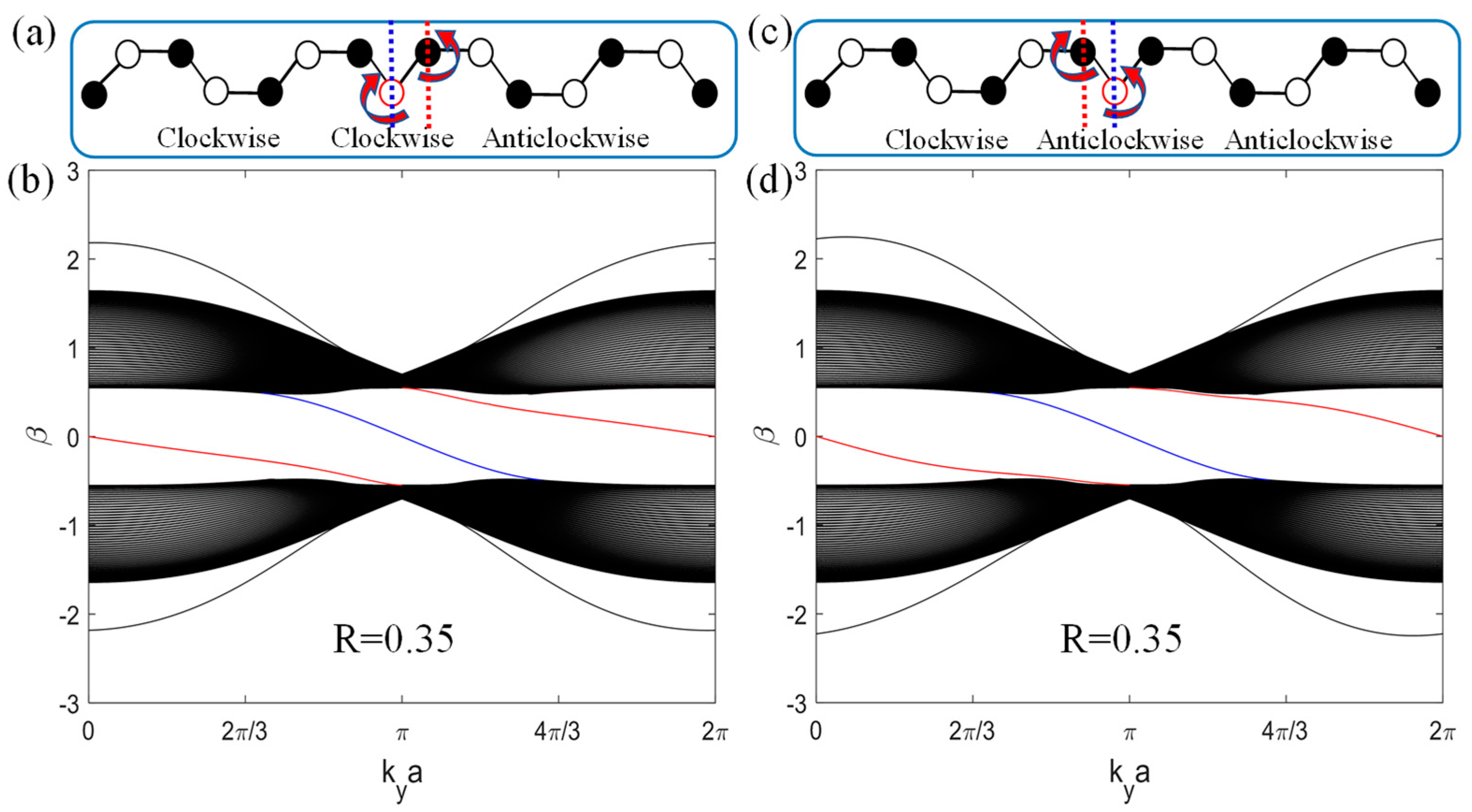
Figure 2a shows the supercell when the middle intersection is a clockwise helical waveguide array. The related edge state dispersion curve can be found in Figure 2b, where the blue and red lines correspond to the blue and red edge states on the DW of Figure 2a, respectively. The blue line represents the zigzag edge of the clockwise helix lattice on the left ( x m , n 0 ) , whereas the red line represents the bearded edge of the anticlockwise helix lattice on the right ( x m , n > 0 ) .
Figure 2c shows the supercell when the middle intersection is an anticlockwise helical waveguide array. The corresponding edge state dispersion curve can be found in Figure 2d, where the blue and red lines correspond to the blue and red edge states on the DW of Figure 2c, respectively. The red line is the bearded edge of the clockwise helix lattice on the left ( x m , n < 0 ) , and the blue line is the zigzag edge of the anticlockwise helix lattice on the right ( x m , n 0 ) .
The gap Chern number C g a p can be used to predict the existence of edge states in composite arrays; it provides a direct way to check whether a given system has edge states and is robust to various forms of impurities [39,54,67]. Generally, the Chern number of a two-band system can be expressed as C = [ k F B Z d [ ( k x d ) × ( k y d ) ] / d 3 d k x d k y ] / ( 4 π ) ; the equivalent Hamiltonian of the system is H e f f ( k ) = d ( k ) σ + d 0 ( k ) , where d ( k ) = [ d x ( k ) , d y ( k ) , d z ( k ) ] , the Pauli matrix vector is σ = [ σ x , σ y , σ z ] , and d 0 ( k ) is the energy constant term associated with k x and k y [40]. When two opposite helical lattices share a straight waveguide array coupling, the straight waveguide does not change the topological properties of the helical waveguide lattice. Therefore, the gap Chern number of the clockwise helical lattice sharing a straight waveguide array is C g a p L = 1 ; the gap Chern number of the anticlockwise helical lattice is C g a p R = 1 . The gap Chern number on both sides is discontinuous, so that topological edge states occur on the DWs, and the corresponding Chern number is C v 1 = | C g a p R C g a p L | = 2 . Similarly, in the case of sharing a clockwise (or anticlockwise) helix waveguide array, the Chern number of the edge states on the DW is C v 2 = 2 , which is consistent with the number of edge states in the dispersion curves (Figure 1d and Figure 2b,d).
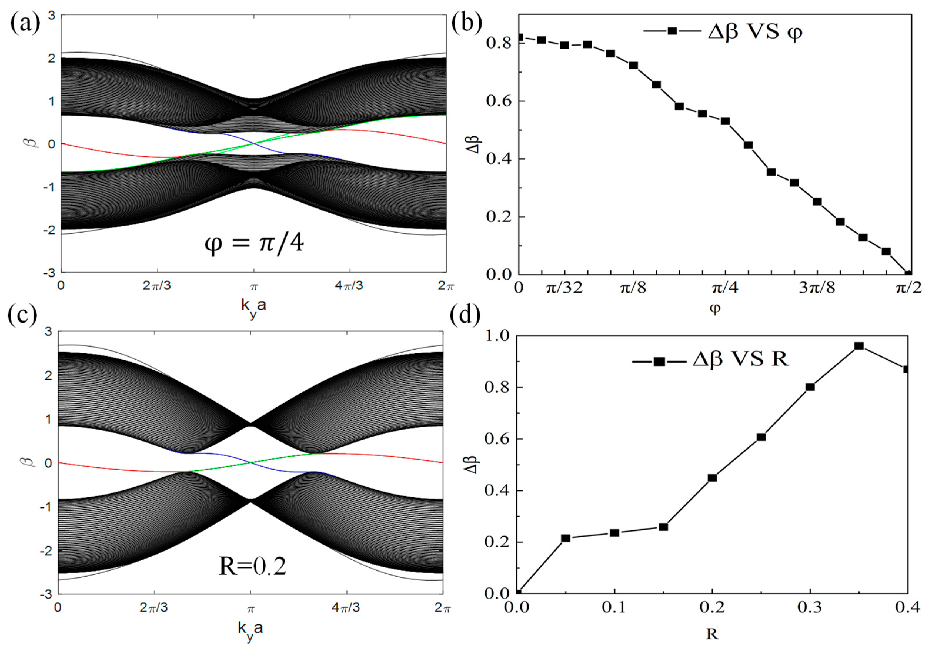
Ke et al. [68] verified that non-uniform distortions could induce overall energy transfer, generate a pseudo-magnetic field, and produce well-defined Landau levels. Pseudo-magnetic fields in the opposite direction could lead to magnetic plasmon snake states at the center of the band, forming pure magnetic plasmon valley currents. Similarly, Huang et al. [69] observed that in a simplified tight-binding model, quantized electron conductivity remained robust under significant disorder strength. Thus, in this work, we discuss the impact of strain on the bandgap and edge states in a shared coupling structure. The helical modulation phase factor φ was introduced in anticlockwise helical waveguides to simulate strain. Here, we only show the case of a straight waveguide array in the middle intersection. We found that the band gap width significantly decreased at φ = π / 4 in Figure 3a, compared with Figure 1d. In addition, when the phase factor was 0 φ π / 2 , the band gap width decreased with an increase in the phase factor, as shown in Figure 3b. The introduction of the phase modulation factor, i.e., strain, leads to structural asymmetry. It affects the coupling coefficients between the waveguides, thereby influencing the bandgap width and edge state transmission characteristics. In addition to adjusting the phase modulation factor, we explored the impact of varying R of the spiral waveguide on the properties of the edge states. To reduce the helical radius to R = 0.2 , we found that the band gap width significantly decreased compared with Figure 1d, as shown in Figure 3c. Further, when R > 0.35 , the waveguides on both sides of the DW overlapped when rotating, which was not considered. When 0 R 0.35 , the band gap width increased with an increase in the waveguide helical radius, as shown in Figure 3d. The positions of the waveguides at the junction dynamically changed depending on the different shared waveguide coupling structures. Therefore, when calculating DW spacing and considering DW characteristics, we chose different spiral radii R to account for these dynamic variations. For the shared direct waveguide coupling structure, the position of the direct waveguide at the junction ( x = 0 ) remained fixed. After calculating DW spacing and considering DW characteristics, the optimal spiral radius R for the shared direct coupling structure was chosen to be 0.3, as it provided the best coupling effect. However, when sharing clockwise (or anticlockwise) waveguide coupling, the positions of the clockwise (or anticlockwise) spiral waveguides at the junction ( x = 0 ) also dynamically changed. For this configuration, the spiral radius R of 0.35 was selected, as it provided the best coupling effect and edge state characteristics.
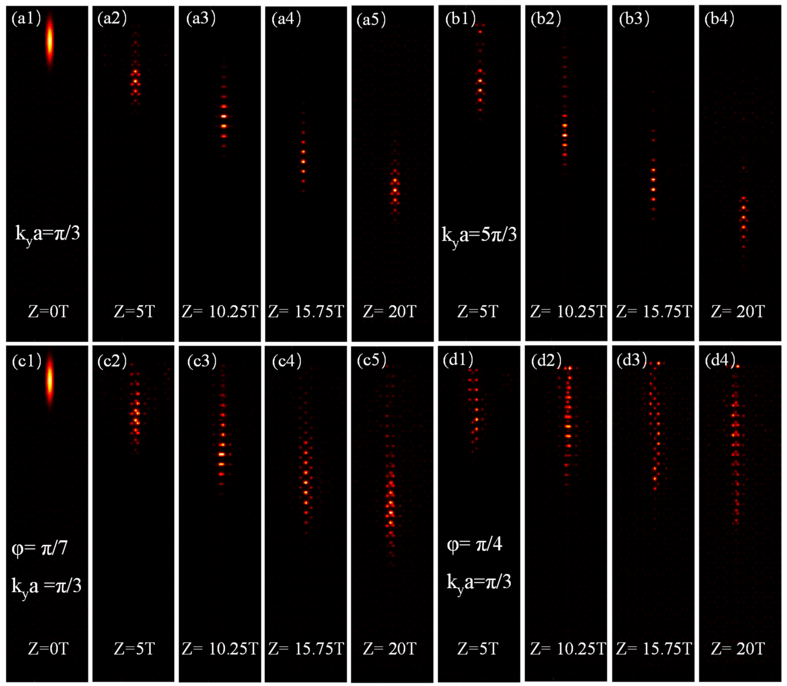
We further verified the existence and properties of the DW edge states by simulating beam propagation on our lattice structures. We launched an elongated Gaussian beam G ( x , y , 0 ) = A 0 exp ( x 2 / ω x 2 y 2 / ω y 2 ) exp ( i k y y ) into the DW, where A 0 = 1 , ω x = 1 a , ω y = 5 a , and k y [ 0 : 2 π / a ] is the k y coordinate point in the Brillouin zone. In this work, the lattice size of L x = 22 a , L y = 30 3 a was used for the three structural transmissions. To facilitate the observation of DW transmission characteristics, the transmission images presented in the paper were designed to highlight the DW, with dimensions consistently set at L x = 10 a , L y = 30 3 a . Firstly, the transport phenomena on the DW of the two opposite helical lattices sharing the straight waveguide array coupling are discussed. The lattice incidence location, x 0 = 0 , y 0 = 24 a , is shown in Figure 4(a1,c1).
From Figure 4(a1–a5,b1–b4), we find that the beam locally transmits stably on the straight waveguide in one direction and does not get dispersed into the lattice when k y a = π / 3 and k y a = 5 π / 3 . Additionally, their transmission speed is different. When we introduce the phase factor into the anticlockwise helical modulation factor for transmission at k y a = π / 3 , the transmission results are shown in Figure 4(c1–c5,d1–d4) with φ = π / 7 and φ = π / 4 , respectively. Obviously, when the phase factor increases in the range of 0 φ π / 2 , the transmission speed of the edge states slows down, and the transmission stability deteriorates because their band gap width gets narrower, as depicted in Figure 3b. For the shared straight waveguide coupling structure, due to the simultaneous coupling of the left clockwise waveguide and the right anticlockwise waveguide with the straight waveguide, the control of the DW edge state characteristics becomes more flexible through phase factor modulation. In other words, introducing phase factors in either clockwise or anticlockwise waveguides can adjust the edge states, and simultaneously changing the phase modulation factors of clockwise and anticlockwise spiral waveguides can also influence the DW edge states. Similarly, the transmission verifies the influence of the control of the spiral radius R on the edge state. When comparing Figure 5(a1–a4) with Figure 4(a2–a5), we also find that the transmission stability of the edge state deteriorates at R = 0.2 due to the narrowing of the band gap width, as shown in Figure 3d.
To validate the robustness of the edge states in DW within the shared straight waveguide coupling structure, we introduced various defects of different sizes, positions, and types. Firstly, we discussed the influence of defect size on the robustness of DW edge states. By removing one anticlockwise spiral waveguide within the DW, we created a defect of length size D y = 2 3 a , as shown in Figure 5(b1). The results revealed that the edge states within the DW can pass through the defect stably without dispersion, as depicted in Figure 5(b2,b3). Subsequently, we increased the size of the defect by removing two consecutive anticlockwise spiral waveguides within the DW, constructing a defect of length size D y = 3 3 a , as shown in the illustration in Figure 5(c1). In this scenario, the edge states within the DW remained stable while passing through the defect, as seen in Figure 5(c1,c2). However, when the defect length size reached D y = 4 3 a , as shown in the illustration in Figure 5(d1), there was some slight scattering, and with larger defect length sizes, dispersion effects became more pronounced. Therefore, in the shared straight waveguide coupling structure, the length of the defect should be less than D y = 4 3 a for the system in this work ( L x = 22 a , L y = 30 3 a ). Secondly, we discussed the impact of the defect position on the robustness of edge states. As shown in the illustration in Figure 5(e1), we simultaneously removed one anticlockwise waveguide and one clockwise waveguide within the DW. The results indicated that the light beam could pass through the defect stably without scattering. This suggests that in the shared straight waveguide coupling structure, edge states exhibit robustness to defects at any position. Lastly, we explored the effect of the defect type on the robustness of edge states. When 16 3 a < L y 19 a , we gradually shifted the lattice to the right by the length of L x = a each time, creating a 150° twisted surface DW defect, as shown in Figure 5(f1), where the scale is L x = 7 a , L y = 30 3 a . The transmission results showed that the light beam could stably pass through the 150° DW defect without dispersion, confirming the robustness of edge states when in the presence of such twisted defects within the shared straight waveguide coupling structure. In summary, for the shared straight waveguide coupling structure, it is crucial to consider defect size as excessively large defects can cause dispersion in the transmission of edge states. The position of the defects can be random, and any waveguide can be randomly removed from the DW. The type of defect, such as a 150° twist, does not compromise the stability of the edge states. These findings demonstrate the robustness of the edge states in the shared straight waveguide coupling structure.
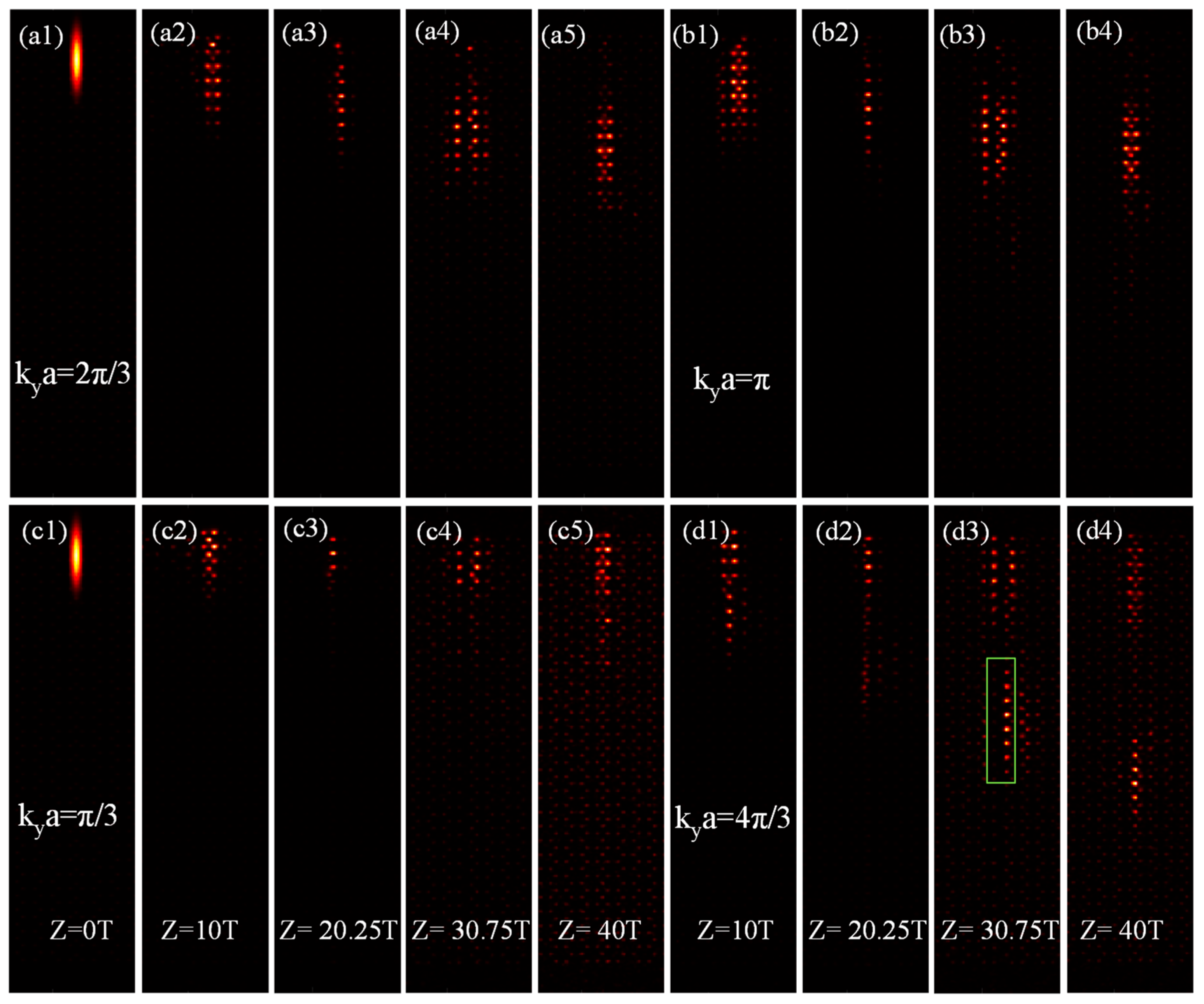
Similarly, the transport phenomena on the DW of the two opposite helical lattices sharing the clockwise (or anticlockwise) helical waveguide array coupling are discussed, as shown in Figure 6 and Figure 7. Firstly, for the shared clockwise waveguide coupling structure, the unidirectional and stable transmission of beams on the DW is driven by zigzag edge states on the left of the DW and bearded edge states on the right of the DW (see blue and red lines in Figure 2a), at k y a = 2 π / 3 and k y a = π in Figure 6(a1–a5,b1–b4). As the slope of the dispersion curve is proportional to the transmission group velocity, and the zigzag edge state on the left of the DW has a higher group velocity than the bearded edge state on the right of the DW (as seen in Figure 2b), the zigzag edge state with a higher group velocity drives the bearded edge state with a lower group velocity to be transported together.
The transmission results for when k y a = π / 3 are shown in Figure 6(c1–c5). The DW does not drive the transmission effectively because the edge state only corresponds to the bearded edge states of the anticlockwise helix lattice on the right (red lines in Figure 2a,b), its slope is close to the flat band, and the transverse group velocity is too small to independently drive transport.
The transmission results for when k y a = 4 π / 3 are shown in Figure 6(d1–d4). The edge state significantly disperses. The bearded edge state of the corresponding anticlockwise helical lattice on the right (red line in Figure 2b) cannot drive the transport independently. In addition, the corresponding zigzag edge state of the clockwise helical lattice on the left (blue line in Figure 2b) can be transported, but the zigzag edge state is close to the bulk band, resulting in dispersion. Moreover, the group velocity of the zigzag edge state decreases, which cannot effectively drive the bearded edge state transport. Thus, transport is driven only on the zigzag edge of the clockwise helical waveguide on the left, as shown in Figure 6(d3). Secondly, for the shared anticlockwise waveguide coupling structure, which is shown in Figure 7, the transport results are similar to what is shown in Figure 6, with the only difference being the positions of the corresponding zigzag edge states and bearded edge states. When k y a = 4 π / 3 , the beam only drives the transmission at the zigzag edge of the anticlockwise helical waveguide on the right (Figure 7(d3)), which is different from that on the DW of the shared clockwise waveguide coupling structure (Figure 6(d3)).
Analogous to the results from introducing defects in the DW for the shared straight waveguide coupling structure, for the shared clockwise (or anticlockwise) waveguide coupling structure, only the defect size needs to be considered. Introducing defects at random positions within the DW will still maintain the stability of the edge states. Moreover, for the shared clockwise waveguide coupling structure, during transmission, the left zigzag edge state drives the right bearded edge state. Therefore, introducing phase factors in the anticlockwise waveguide can more effectively control the DW edge states. Similarly, for the shared anticlockwise waveguide coupling structure, it is more effective to control the DW edge states by introducing phase factors in the clockwise waveguide.
This study used MATLAB for simulations, which were run on a Lenovo laptop. The laptop was equipped with an Intel Core i7-8550U (1.8 GHz/L3 8M, Santa Clara, CA, USA) processor 8 GB of DDR4 memory, a 1 TB hard drive, and an independent AMD Radeon RX 550 graphics card, Santa Clara, CA, USA. The computation times for calculating the dispersion structures of the shared straight, clockwise, and anticlockwise waveguide coupling structures were 9.3639, 9.5509, and 9.4742 s, respectively. In the shared straight waveguide coupling structure, the computation time for simulating 20 T of transmission was 126.6588 s. In the shared clockwise/anticlockwise waveguide coupling structure, the computation time for simulating 40 T of transmission was 291.8945 and 288.3710 s, respectively.

4. Conclusions

Three kinds of FTI DW structures were designed in this study, composed of opposite helical waveguides and straight, clockwise, and anticlockwise shared waveguides. Based on the tight binding theory model, we investigated the existence, types, and robustness of the edge states in these structures. Our results showed that the structure coupled by two opposite helical waveguides sharing the middle node waveguide array did not affect the overall topological invariant of the system. The existence type of the edge states varied with the shared coupling structure, and the transmission rate of the edge states varied with the degree of coupling between the shared waveguides. The edge states in all three structure types exhibited robustness and were immune to defects of any position or type. The properties of the edge states could be regulated by modulating the phase factor and helical radii. The methods for controlling the edge states in different shared coupling structures are provided. This may help deepen our understanding of how topological structures influence the electronic and photonic properties of materials, inspiring the design and development of novel topological devices.

Author Contributions

Conceptualization, Z.S.; methodology, J.W., X.J. and Y.Z.; software, J.W.; validation, J.W., X.J. and H.L.; formal analysis, Y.D.; investigation, Z.S., Y.D. and K.X.; writing—original draft preparation, J.W.; writing—review and editing, Z.S. and K.X.; funding acquisition, Y.D. and K.X. All authors have read and agreed to the published version of the manuscript.

Funding

This work was funded by the Guangdong Basic and Applied Basic Research Foundation (2020A1515010623), the Leading Talents of Guangdong Province Program, and the Natural Science Foundation of China (11874126, 52175457).

Institutional Review Board Statement

Not applicable.

Informed Consent Statement

Informed consent was obtained from all subjects involved in the study.

Data Availability Statement

The data presented in this study are available upon request from the corresponding author. The data are not publicly available due to privacy restrictions.

Acknowledgments

This work was supported by the Guangdong Basic and Applied Basic Research Foundation (2020A1515010623), the Leading Talents of Guangdong Province Program, and the Natural Science Foundation of China (11874126, 52175457).

Conflicts of Interest

The authors declare no conflict of interest.

References

  1. Li, J.; Li, J.T.; Yue, Z.; Zheng, C.L.; Wang, G.C.; Liu, J.Y.; Xu, H.; Song, C.Y.; Yang, F.; Li, H.; et al. Structured Vector Field Manipulation of Terahertz Wave along the Propagation Direction Based on Dielectric Metasurfaces. Laser Photonics Rev. 2022, 16, 2200325. [Google Scholar] [CrossRef]
  2. Reserbat-Plantey, A.; Epstein, I.; Torre, I.; Costa, A.T.; Goncalves, P.A.D.; Mortensen, N.A.; Polini, M.; Song, J.C.W.; Peres, N.M.R.; Koppens, F.H.L. Quantum Nanophotonics in Two-Dimensional Materials. ACS Photonics 2021, 8, 85–101. [Google Scholar] [CrossRef]
  3. Tang, G.J.; He, X.T.; Shi, F.L.; Liu, J.W.; Chen, X.D.; Dong, J.W. Topological Photonic Crystals: Physics, Designs, and Applications. Laser Photonics Rev. 2022, 16, 2100300. [Google Scholar] [CrossRef]
  4. Li, C.; Hu, X.Y.; Yang, H.; Gong, Q.J. Unidirectional transmission in 1D nonlinear photonic crystal based on topological phase reversal by optical nonlinearity. AIP Adv. 2017, 7, 025203. [Google Scholar] [CrossRef]
  5. Wu, Y.; Li, C.; Hu, X.Y.; Ao, Y.T.; Zhao, Y.F.; Gong, Q.H. Applications of Topological Photonics in Integrated Photonic Devices. Adv. Opt. Mater. 2017, 5, 1700357. [Google Scholar] [CrossRef]
  6. Bonnell, D.A.; Basov, D.N.; Bode, M.; Diebold, U.; Kalinin, S.V.; Madhavan, V.; Novotny, L.; Salmeron, M.; Schwarz, U.D.; Weiss, P.S. Imaging physical phenomena with local probes: From electrons to photons. Rev. Mod. Phys. 2012, 84, 1343. [Google Scholar] [CrossRef]
  7. Prabha, K.R.; Kavitha, V.; Robinson, S.; Jayabharathan, J.K.; Balamurugan, P. Two-dimensional photonic crystal-based half adder: A review. J. Opt. 2022, 51, 415–436. [Google Scholar] [CrossRef]
  8. Liu, R.X.; Cai, Z.Y.; Zhang, Q.S.; Yuan, H.; Zhang, G.L.; Yang, D. Colorimetric two-dimensional photonic crystal biosensors for label-free detection of hydrogen peroxide. Sens. Actuators B Chem. 2022, 354, 131236. [Google Scholar] [CrossRef]
  9. Balaji, V.R.; Murugan, M.; Robinson, S.; Hegde, G. A Novel Hybrid Channel DWDM Demultiplexer Using Two Dimensional Photonic Crystals Meeting ITU Standards. Silicon 2022, 14, 617–628. [Google Scholar] [CrossRef]
  10. Latha, K.; Arunkumar, R.; Prabha, K.R.; Robinson, S. Performance analysis of all optical 4*2 and 8*3 encoder using two dimensional photonic crystals waveguides. Silicon 2021, 14, 3245–3258. [Google Scholar] [CrossRef]
  11. Markel, V.A.; Schoebinger, M.; Hollaus, K. A fast method to compute dispersion diagrams of three-dimensional photonic crystals with rectangular geometry. Comput. Phys. Commun. 2022, 279, 108441. [Google Scholar] [CrossRef]
  12. Zhang, X.; Yang, Y.; Xue, P.; Valenzuela, C.; Chen, Y.; Yang, X.; Wang, L.; Feng, W. Three-Dimensional Electrochromic Soft Photonic Crystals Based on MXene-Integrated Blue Phase Liquid Crystals for Bioinspired Visible and Infrared Camouflage. Angew. Chem. Int. Ed. 2022, 134, e202211030. [Google Scholar] [CrossRef]
  13. Deng, W.M.; Chen, Z.M.; Li, M.Y.; Guo, C.H.; Tian, Z.T.; Sun, K.X.; Chen, X.D.; Chen, W.J.; Dong, J.W. Ideal nodal rings of one-dimensional photonic crystals in the visible region. Light Sci. Appl. 2022, 11, 134. [Google Scholar] [CrossRef] [PubMed]
  14. Wang, Z.H.; Liu, D.J.; Teo, H.T.; Wang, Q.; Xue, H.R.; Zhang, B.L. Higher-order Dirac semimetal in a photonic crystal. Phys. Rev. B 2022, 105, L060101. [Google Scholar] [CrossRef]
  15. Qiu, Y.; Yang, Y.; Valenzuela, C.; Zhang, X.; Yang, M.; Xue, P.; Ma, J.; Liu, Z.; Wang, L.; Feng, W. Near-Infrared Light-Driven Three-Dimensional Soft Photonic Crystals Loaded with Upconversion Nanoparticles. Adv. Opt. Mater. 2022, 10, 2102475. [Google Scholar] [CrossRef]
  16. Rabus, D.G.; Sada, C.; Rabus, D.G.; Sada, C. Ring resonators: Theory and modeling. In Integrated Ring Resonators: A Compendium; Springer: Cham, Switzerland, 2020; pp. 3–46. [Google Scholar] [CrossRef]
  17. Steglich, P.; Hulsemann, M.; Dietzel, B.; Mai, A. Optical Biosensors Based on Silicon-On-Insulator Ring Resonators: A Review. Molecules 2019, 24, 519. [Google Scholar] [CrossRef]
  18. Taishi, B.Y.; Yang, Y.T.; Wu, X.Q.; Xu, J.C.; Huang, S.G. Dual-band 3D electrically small antenna based on split ring resonators. Adv. Compos. Hybrid Mater. 2022, 5, 350–355. [Google Scholar] [CrossRef]
  19. Moradi, M.; Mohammadi, M.; Olyaee, S.; Seifouri, M. Design and Simulation of a Fast All-Optical Modulator Based on Photonic Crystal Using Ring Resonators. Silicon 2022, 14, 765–771. [Google Scholar] [CrossRef]
  20. Zhu, C.; Zhuang, Y. Microwave photonic fiber ring resonator. Sensors 2022, 22, 3771. [Google Scholar] [CrossRef]
  21. Lee, D.; So, S.; Hu, G.; Kim, M.; Badloe, T.; Cho, H.; Kim, J.; Kim, H.; Qiu, C.-W.; Rho, J. Hyperbolic metamaterials: Fusing artificial structures to natural 2D materials. eLight 2022, 2, 1. [Google Scholar] [CrossRef]
  22. Indukuri, S.R.K.C.; Frydendahl, C.; Sharma, N.; Mazurski, N.; Paltiel, Y.; Levy, U. Enhanced Chiral Sensing at the Few-Molecule Level Using Negative Index Metamaterial Plasmonic Nanocuvettes. ACS Nano 2022, 16, 17289–17297. [Google Scholar] [CrossRef] [PubMed]
  23. Zhang, P.; Leng, Q.; Kan, Y.S.; Ge, J.; Wu, S. Asymmetric transmission of linearly polarized waves based on chiral metamaterials. Opt. Commun. 2022, 517, 128321. [Google Scholar] [CrossRef]
  24. Su, Z.P.; Wang, Y.K. Anisotropic Photonics Topological Transition in Hyperbolic Metamaterials Based on Black Phosphorus. Nanomaterials 2020, 10, 1694. [Google Scholar] [CrossRef] [PubMed]
  25. Guo, Z.W.; Wu, X.; Sun, Y.; Jiang, H.T.; Ding, Y.Q.; Li, Y.H.; Zhang, Y.W.; Chen, H. Anomalous broadband Floquet topological metasurface with pure site rings. Adv. Photonics Nexus 2023, 2, 016006. [Google Scholar] [CrossRef]
  26. Li, L.Q.; Kong, W.J.; Chen, F. Femtosecond laser-inscribed optical waveguides in dielectric crystals: A concise review and recent advances. Adv. Photonics 2022, 4, 024002. [Google Scholar] [CrossRef]
  27. Zhang, K.V.; Boehm, G.; Belkin, M.A. Mid-infrared microring resonators and optical waveguides on an InP platform. Appl. Phys. Lett. 2022, 120, 061106. [Google Scholar] [CrossRef]
  28. Chen, T.; Dang, Z.; Ding, Z.; Liu, Z.; Zhang, Z. Multibit NOT logic gate enabled by a function programmable optical waveguide. Opt. Lett. 2022, 47, 3519–3522. [Google Scholar] [CrossRef]
  29. Leal, A.; Avellar, L.; Biazi, V.; Soares, M.S.; Frizera, A.; Marques, C. Multifunctional flexible optical waveguide sensor: On the bioinspiration for ultrasensitive sensors development. Opto-Electron. Adv. 2022, 5, 210098. [Google Scholar] [CrossRef]
  30. Zhu, T.Q.; Zhang, J.T.; Zhang, H.F. Investigation of photonic band gap properties of one-dimensional magnetized plasma spherical photonic crystals. Waves Random Complex Media 2023. [Google Scholar] [CrossRef]
  31. Wang, X.X.; Guo, Z.W.; Song, J.; Jiang, H.T.; Chen, H.; Hu, X. Unique Huygens-Fresnel electromagnetic transportation of chiral Dirac wavelet in topological photonic crystal. Nat. Commun. 2023, 14, 304010. [Google Scholar] [CrossRef]
  32. Zhang, H.Y.; Li, J.; Jiang, H.W.; Li, N.; Wang, J.S.; Xu, J.P.; Zhu, C.J.; Yang, Y.P. Coherent interaction of a quantum emitter and the edge states in two-dimensional optical topological insulators. Phys. Rev. A 2022, 105, 053703. [Google Scholar] [CrossRef]
  33. Pelucchi, E.; Fagas, G.; Aharonovich, I.; Englund, D.; Figueroa, E.; Gong, Q.H.; Hannes, H.; Liu, J.; Lu, C.Y.; Matsuda, N.; et al. The potential and global outlook of integrated photonics for quantum technologies. Nat. Rev. Phys. 2022, 4, 194–208. [Google Scholar] [CrossRef]
  34. Kim, M.; Jacob, Z.; Rho, J. Recent advances in 2D, 3D and higher-order topological photonics. Light Sci. Appl. 2020, 9, 130. [Google Scholar] [CrossRef] [PubMed]
  35. Wang, T.; Hu, S.J.; Eggert, S.; Fleischhauer, M.; Pelster, A.; Zhang, X.F. Floquet-induced superfluidity with periodically modulated interactions of two-species hardcore bosons in a one-dimensional optical lattice. Phys. Rev. Res. 2020, 2, 013275. [Google Scholar] [CrossRef]
  36. Fang, K.J.; Yu, Z.F.; Fan, S.H. Realizing effective magnetic field for photons by controlling the phase of dynamic modulation. Nat. Photonics 2012, 6, 782–787. [Google Scholar] [CrossRef]
  37. Yang, Z.J.; Lustig, E.; Lumer, Y.; Segev, M. Photonic Floquet topological insulators in a fractal lattice. Light Sci. Appl. 2020, 9, 128. [Google Scholar] [CrossRef]
  38. Pasek, M.; Chong, Y.D. Network models of photonic Floquet topological insulators. Phys. Rev. B 2014, 89, 075113. [Google Scholar] [CrossRef]
  39. Rechtsman, M.C.; Zeuner, J.M.; Plotnik, Y.; Lumer, Y.; Podolsky, D.; Dreisow, F.; Nolte, S.; Segev, M.; Szameit, A. Photonic Floquet topological insulators. Nature 2013, 496, 196–200. [Google Scholar] [CrossRef]
  40. Haldane, F.D.M. Model for a quantum Hall effect without Landau levels: Condensed-matter realization of the “parity anomaly”. Phys. Rev. Lett. 1988, 61, 2015. [Google Scholar] [CrossRef]
  41. Price, H.; Chong, Y.D.; Khanikaev, A.; Schomerus, H.; Maczewsky, L.J.; Kremer, M.; Heinrich, M.; Szameit, A.; Zilberberg, O.; Yang, Y.H.; et al. Roadmap on topological photonics. J. Phys. Photonics 2022, 4, 032501. [Google Scholar] [CrossRef]
  42. Barone, S.; Narcowich, M.; Narcowich, F. Floquet theory and applications. Phys. Rev. A 1977, 15, 1109. [Google Scholar] [CrossRef]
  43. Neves, A. Floquet’s Theorem and Stability of Periodic Solitary Waves. J. Dyn. Differ. Equ. 2009, 21, 555–565. [Google Scholar] [CrossRef]
  44. Dai, C.M.; Shi, Z.C.; Yi, X.X. Floquet theorem with open systems and its applications. Phys. Rev. A 2016, 93, 032121. [Google Scholar] [CrossRef]
  45. Bazhan, N.; Malomed, B.; Yakimenko, A. Josephson oscillations of edge quasi-solitons in a photonic-topological coupler. Opt. Lett. 2021, 46, 6067–6070. [Google Scholar] [CrossRef] [PubMed]
  46. Lustig, E.; Weimann, S.; Plotnik, Y.; Lumer, Y.; Bandres, M.A.; Szameit, A.; Segev, M. Photonic topological insulator in synthetic dimensions. Nature 2019, 567, 356–360. [Google Scholar] [CrossRef] [PubMed]
  47. Luo, M. Floquet engineering of two dimensional photonic waveguide arrays with π or ±2π/3 corner states. Opt. Commun. 2023, 534, 129333. [Google Scholar] [CrossRef]
  48. Zhong, H.; Kartashov, Y.V.; Li, Y.D.; Zhang, Y.Q. π-mode solitons in photonic Floquet lattices. Phys. Rev. A 2023, 107, L021502. [Google Scholar] [CrossRef]
  49. Ivanov, S.K.; Kartashov, Y.V.; Maczewsky, L.J.; Szameit, A.; Konotop, V.V. Bragg solitons in topological Floquet insulators. Opt. Lett. 2020, 45, 2271–2274. [Google Scholar] [CrossRef]
  50. Ivanov, S.K.; Kartashov, Y.V.; Szameit, A.; Torner, L.; Konotop, V.V. Vector Topological Edge Solitons in Floquet Insulators. ACS Photonics 2020, 7, 735–745. [Google Scholar] [CrossRef]
  51. Shi, Z.W.; Zuo, M.W.; Li, H.G. Edge states supported by different boundaries of two helical lattices with opposite helicity. Results Phys. 2021, 24, 104191. [Google Scholar] [CrossRef]
  52. Shi, Z.W.; Zuo, M.W.; Li, H.G.; Preece, D.; Zhang, Y.Q.; Chen, Z.G. Topological Edge States and Solitons on a Dynamically Tunable Domain Wall of Two Opposing Helical Waveguide Arrays. ACS Photonics 2021, 8, 1077–1084. [Google Scholar] [CrossRef]
  53. Zhong, H.; Li, Y.D.; Song, D.H.; Kartashov, Y.V.; Zhang, Y.Q.; Zhang, Y.P.; Chen, Z.G. Topological Valley Hall Edge State Lasing. Laser Photonics Rev. 2020, 14, 2000001. [Google Scholar] [CrossRef]
  54. Ozawa, T.; Price, H.M.; Amo, A.; Goldman, N.; Hafezi, M.; Lu, L.; Rechtsman, M.C.; Schuster, D.; Simon, J.; Zilberberg, O. Topological photonics. Rev. Mod. Phys. 2019, 91, 015006. [Google Scholar] [CrossRef]
  55. Ningyuan, J.; Owens, C.; Sommer, A.; Schuster, D.; Simon, J. Time- and Site-Resolved Dynamics in a Topological Circuit. Phys. Rev. X 2015, 5, 021031. [Google Scholar] [CrossRef]
  56. He, C.; Ni, X.; Ge, H.; Sun, X.C.; Chen, Y.B.; Lu, M.H.; Liu, X.P.; Chen, Y.F. Acoustic topological insulator and robust one-way sound transport. Nat. Phys. 2016, 12, 1124–1129. [Google Scholar] [CrossRef]
  57. Yan, M.; Lu, J.Y.; Li, F.; Deng, W.Y.; Huang, X.Q.; Ma, J.H.; Liu, Z.Y. On-chip valley topological materials for elastic wave manipulation. Nat. Mater. 2018, 17, 993–998. [Google Scholar] [CrossRef]
  58. Wang, Y.T.; Luan, P.G.; Zhang, S. Coriolis force induced topological order for classical mechanical vibrations. New J. Phys. 2015, 17, 073031. [Google Scholar] [CrossRef]
  59. Martin, I.; Blanter, Y.M.; Morpurgo, A.F. Topological confinement in bilayer graphene. Phys. Rev. Lett. 2008, 100, 036804. [Google Scholar] [CrossRef]
  60. Jung, J.; Zhang, F.; Qiao, Z.H.; MacDonald, A.H. Valley-Hall kink and edge states in multilayer graphene. Phys. Rev. B 2011, 84, 075418. [Google Scholar] [CrossRef]
  61. Lu, J.Y.; Qiu, C.Y.; Ke, M.Z.; Liu, Z.Y. Valley Vortex States in Sonic Crystals. Phys. Rev. Lett. 2016, 116, 093901. [Google Scholar] [CrossRef]
  62. Ablowitz, M.J.; Cole, J.T. Topological insulators in longitudinally driven waveguides: Lieb and Kagome lattices. Phys. Rev. A 2019, 99, 033821. [Google Scholar] [CrossRef]
  63. Bisharat, D.J.; Davis, R.J.; Zhou, Y.; Bandaru, P.R.; Sievenpiper, D.F. Photonic Topological Insulators: A Beginner’s Introduction. IEEE Antennas Propag. Mag. 2021, 63, 112–124. [Google Scholar] [CrossRef]
  64. Orazbayev, B.; Fleury, R. Quantitative robustness analysis of topological edge modes in C6 and valley-Hall metamaterial waveguides. Nanophotonics 2019, 8, 1433–1441. [Google Scholar] [CrossRef]
  65. Kohmoto, M.; Hasegawa, Y. Zero modes and edge states of the honeycomb lattice. Phys. Rev. B 2007, 76, 205402. [Google Scholar] [CrossRef]
  66. Su, W.-P.; Schrieffer, J.R.; Heeger, A.J. Solitons in polyacetylene. Phys. Rev. Lett. 1979, 42, 1698. [Google Scholar] [CrossRef]
  67. Hatsugai, Y. Chern number and edge states in the integer quantum Hall effect. Phys. Rev. Lett. 1993, 71, 3697. [Google Scholar] [CrossRef] [PubMed]
  68. Ke, S.S.; Li, Y.M.; Lou, W.K.; Chang, K. Pure magnon valley currents in a patterned ferromagnetic thin film. Phys. Rev. B 2023, 107, 104426. [Google Scholar] [CrossRef]
  69. Huang, A.H.; Ke, S.S.; Guan, J.H.; Lou, W.K. Tight-binding model and quantum transport with disorder for 1T’transition metal dichalcogenides. J. Appl. Phys. 2023, 134, 084302. [Google Scholar] [CrossRef]
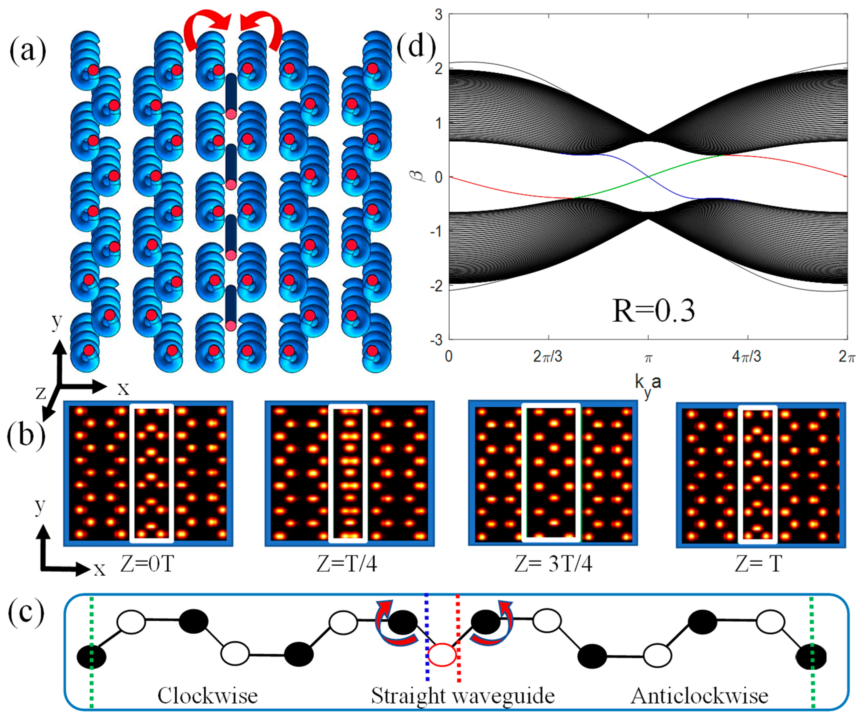
Figure 1. (a) A 3D structure diagram of two opposite helical lattices sharing a straight waveguide array coupling. (b) Dynamic changes of the DW at different periods of (c). (c) Supercell of structure in (a). (d) The dispersion curve of the structure in (a). The parameters are R = 0.3 , φ = 0 . All quantities are plotted in dimensionless units.
Photonics 10 01220 g001
Figure 2. (a) The supercell and (b) dispersion curve when the middle intersection is a clockwise helical waveguide array. (c) The supercell and (d) dispersion curve when the middle intersection is an anticlockwise helical waveguide array. The parameters were R = 0.35 , φ = 0 . All quantities are plotted in dimensionless units.
Photonics 10 01220 g002
Figure 3. (a) The dispersion curve at φ = π / 4 and R = 0.3 . (b) The change in band gap width Δ β with helix modulation phase factor φ when R = 0.3 . (c) The dispersion curve related to Figure 1a at R = 0.2 and φ = 0 . (d) The change in band gap width Δ β with helix radius R when φ = 0 . All quantities are plotted in dimensionless units.
Photonics 10 01220 g003
Figure 4. The transmission of a topological edge state at different propagation distances on the DW of the two opposite helical lattices sharing the straight waveguide array coupling. The normalized wave number changes from (a1a5) k y a = π / 3 to (b1b4) k y a = 5 π / 3 when R = 0.3 , φ = 0 . The modulation phase factor varies from (c1c5) φ = π / 7 to (d1d4) φ = π / 4 when k y a = π / 3 and R = 0.3 . The input beam is launched into the central boundary of the lattice, as shown in (a1,c1). All quantities are plotted in dimensionless units.
Photonics 10 01220 g004
Figure 5. (a1a4) The helix radius changes to R = 0.2 with k y a = π / 3 and φ = 0 . (b1f4) Introduces defects of various sizes, positions, and types within DWs with R = 0.3 , φ = 0 and k y a = π / 3 . (b1d2) Excludes anticlockwise waveguides with different sizes of defects on the DW, where the defect length size is: (b1b3) 2 3 a , (c1,c2) 3 3 a , and (d1,d2) 4 3 a . (e1,e2) Defects have different positions, and one anticlockwise and one clockwise waveguide are simultaneously excluded on the DW. (f1f4) Creating a 150° twisted surface DW defect. The incident beam parameters and position are the same as in Figure 4(a1,c1). All quantities are plotted in dimensionless units.
Photonics 10 01220 g005
Figure 6. The transport phenomena on the DW of the two opposite helical lattices sharing the clockwise helical waveguide array coupling with (a) k y a = 2 π / 3 , (b) k y a = π , (c) k y a = π / 3 , and (d) k y a = 4 π / 3 at R = 0.35 , φ = 0 . All quantities are plotted in dimensionless units.
Photonics 10 01220 g006
Figure 7. The transport phenomena on the DW of the two opposite helical lattices sharing the anticlockwise helical waveguide array coupling with (a) k y a = 2 π / 3 , (b) k y a = π , (c) k y a = π / 3 , and (d) k y a = 4 π / 3 at R = 0.35 , φ = 0 . All quantities are plotted in dimensionless units.
Photonics 10 01220 g007
Disclaimer/Publisher’s Note: The statements, opinions and data contained in all publications are solely those of the individual author(s) and contributor(s) and not of MDPI and/or the editor(s). MDPI and/or the editor(s) disclaim responsibility for any injury to people or property resulting from any ideas, methods, instructions or products referred to in the content.