Abstract
In this study, an elasto-plastic stress analysis is proposed in an aluminum adherend and a ductile adhesive. Elasto-plastic analysis was carried out for the aluminum adherend and DP460 ductile adhesive in a double-lap joint. The analytical solution was compared with the finite element solution. ANSYS 12 was used in the stress analysis. The analytical solution was performed for the one-dimensional case in the adhesive and the adherends. A FEM solution was given for the two-dimensional case. Similar results were obtained for both. In addition, the solution was carried out for brittle and ductile materials. The mechanical properties of the loctite were nearly the same as the ductile DP460 adhesive. It was observed that the ductile adhesive increased the strength of the structure due to the small shear stresses at the free ends of the adhesive.
1. Introduction
One of the significant solutions for ductile adhesives in single lap and double lap joints is elasto-plastic stress analysis. When the external force is applied to the joints, the joint strength can be increase by residual stresses.
An adhesive-bonded double-lap joint has been studied by Hart-Smith [1]. He carried-out an elasto-plastic solution on balanced double-lap joints. He found that the greatest shear stress components were occurring at the free ends of the adhesives. Goeij et al. [2] presented a review of research studies performed on composite joints under cyclic loading. Adhesive bonded single or double-lap joints were investigated in the papers [3,4,5,6,7,8,9]. Elastic-plastic stress analysis was carried out in single-lap adhesively bonded joints by using analytic and finite element solutions [10,11]. Malvade et al. [12] proposed a nonlinear simulation of mechanical behaviors of adhesively bonded joints by using the Drucker–Prager criterion for finding a close solution in experimental load displacement curves. Markolefas and Papathanassiou [13] evolve a shear-lap model for calculating the stress distributions in double lap joints under axial cyclic loading. In that study the adhesive layers satisfy the perfectly elastic plastic properties. Elastic-plastic stress analysis was derived from papers [14,15,16].
In this study, an analytical elasto-plastic solution is proposed for a double-lap joint. The solution is carried out in a ductile adhesive and a ductile aluminum adherend. The analytical solution is managed by the finite element analysis. A good agreement is received between them. In the solution, outer adherends are selected as aluminum alloy and a middle adherend is chosen as a soft ductile aluminum. As a result of this, the middle adherend yields the plastic deformation. In addition, the shear stress in the adhesive is compared for ductile and brittle adhesives.
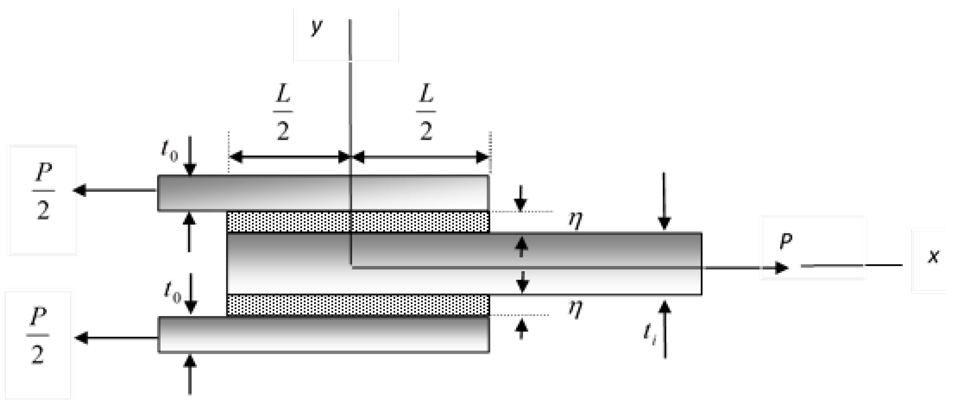
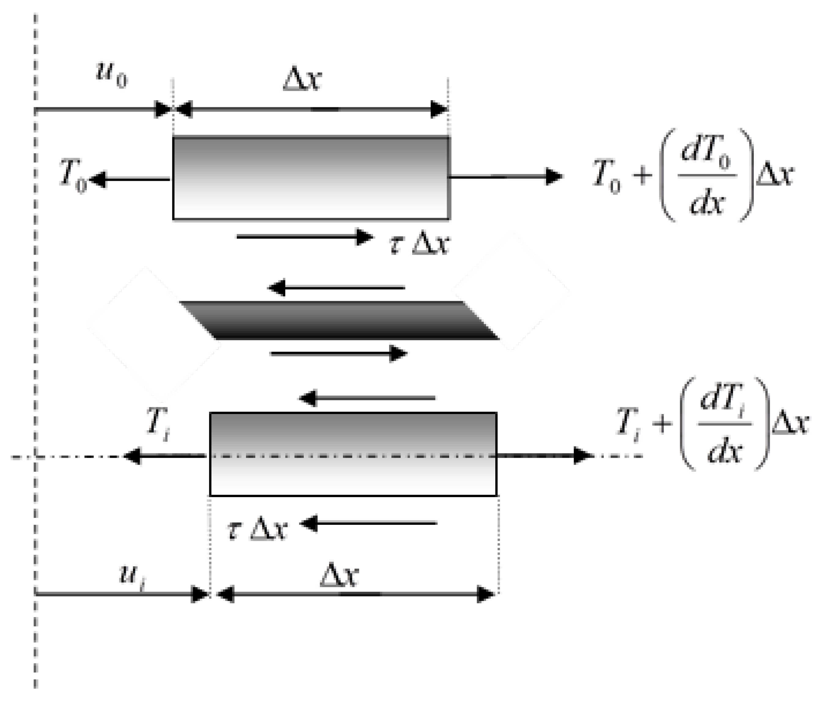
2. Mathematical Solution
In this study, elasto-plastic solutions of the shear stresses in the adhesive and the normal stresses in the adherend were carried out analytically and numerically, as shown in Figure 1.
Figure 1.
Schematic view of the double-lap joint.
In the solution, some basic assumptions have been proposed:
- (a)
- Shear stress does not vary through the thickness;
- (b)
- Longitudinal stresses in the adherend do not vary through the thickness;
- (c)
- The normal stresses along the adhesive are neglected.
The static equilibrium of infinite small elements produces the relations shown in Figure 2.
Figure 2.
The free body diagram of double-lap joint.
The second element yields,
where are the longitudinal stresses per unit width in the outer and middle adherends, respectively. is written as shown in Figure 2.
The strain increment of can be written in the differential form as,
If it both sides are divided by ,
where is the thickness and is the shear modulus of the adhesive. can be determined from the equivalent plastic strain formula as in Mendelson [17]:
by using the Ludwick equation, for a bilinear case,
or
where is the plastic constant of the adhesive.
can be calculated using the von Mises criterion:
The plastic strain increment is written as:
and
Equation (7) can be written as:
or
If = ,
then Equation (15) becomes:
In this study, it is assumed that only the middle adherend undergoes plastic deformation.
Equation (16) can be written as:
where
or
where and are the thickness and the modulus of elasticity of the middle adherend, respectively.
After integration,
If the integration constant C is obtained from the initial case as, C = 0, then
where is the yield strength of the middle adherend, or , which is the stress at the yield point.
Placing this in Equation (17), it becomes
where and are the thickness and the modulus of the elasticity of the outer adherends, respectively.
Placing this in Equation (21), it becomes
where
If it is said ,
the governing equation becomes:
The solution of the above equation is:
The boundary conditions are as follows:
The solution of Equation (22) under the boundary conditions is
and the shear stress in the adhesive is obtained as
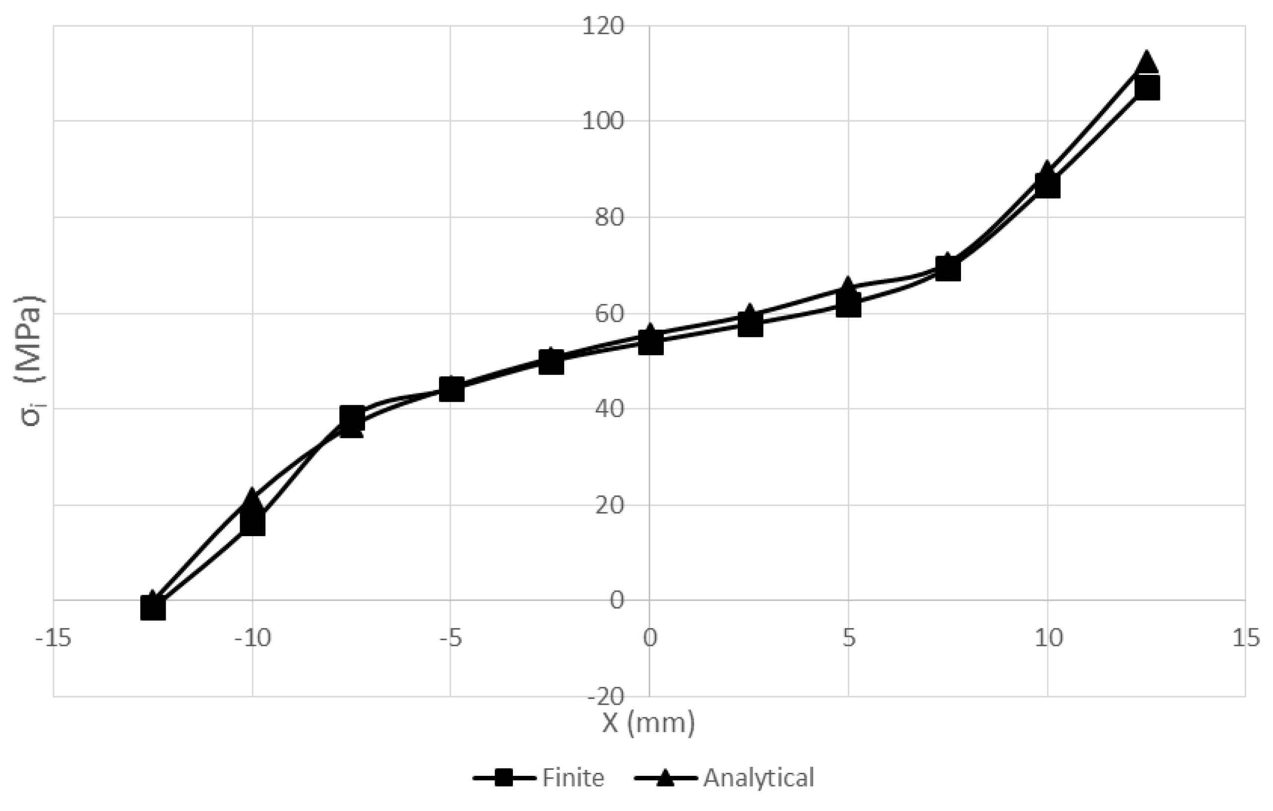
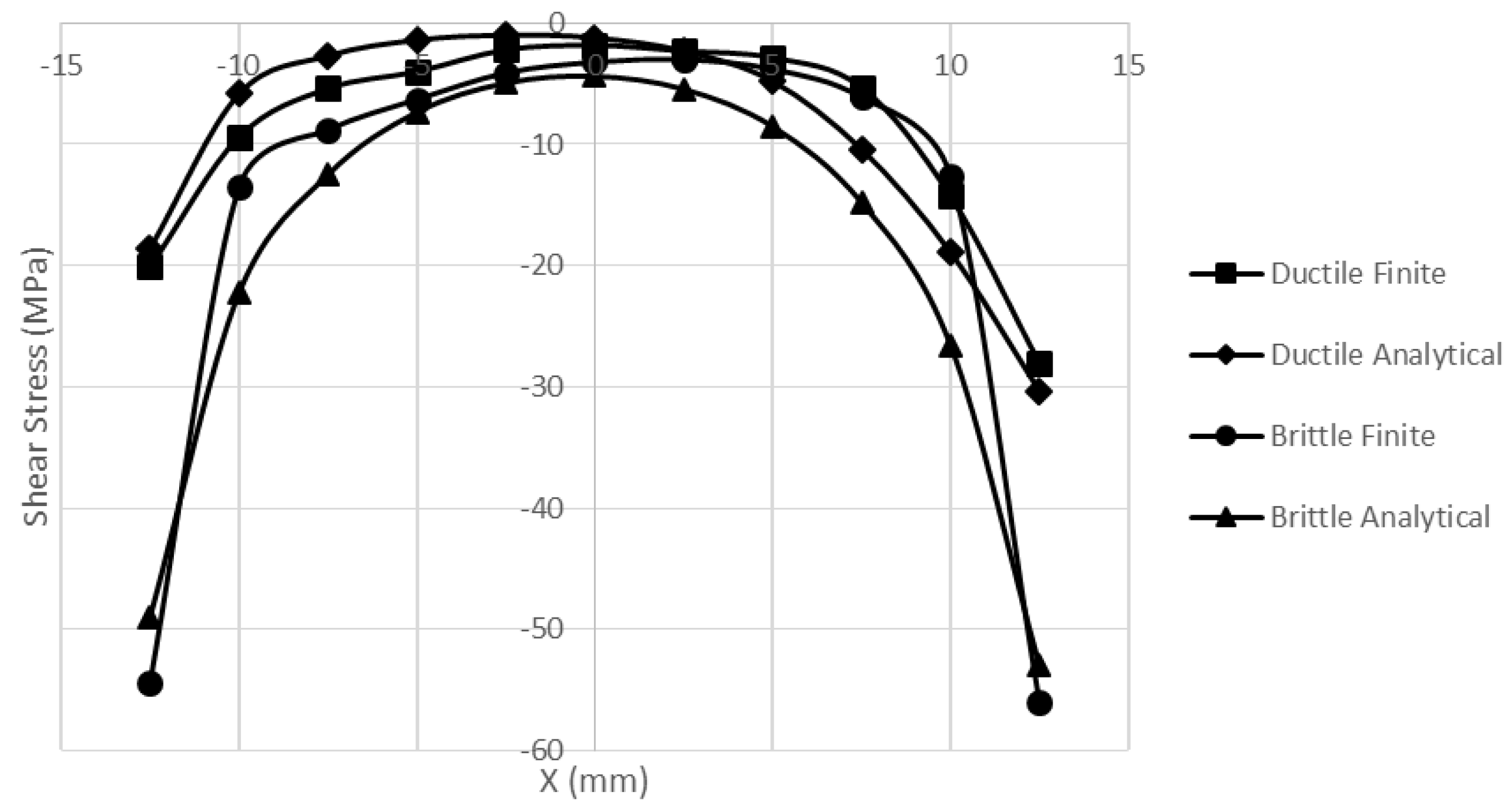
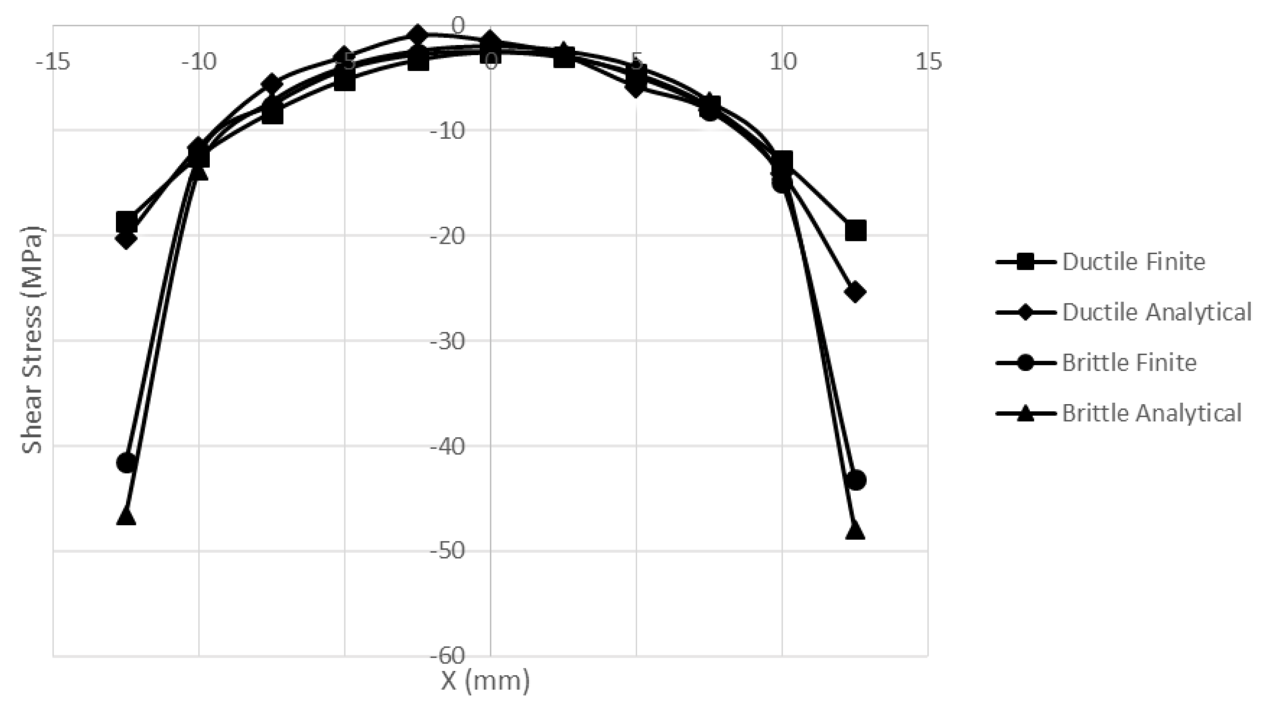
3. Results & Discussion
In this investigation an analytical solution was carried out in a double-lap joint with a ductile adhesive. The adherends were chosen as different aluminum plates. The middle adherend (Ti) was subjected to plastic deformation; however, the outer adherends (To) were elastic. In Figure 3, the displacement of the Y axis, which is denoted as uY, is equal to zero in the middle of the adherend. In addition, the displacement of the X axis, which is denoted as uX, is equal to zero in the outer adherend. These displacement values were chosen for satisfying the boundary conditions.
Figure 3.
Schematic view of the half of double lap joint.
The mechanical properties of DP460 are given in Table 1. In general, the ductile adhesive increases the failure strength of the joints. In this solution, n is taken to be 1 to get a bilinear solution. The mechanical properties of the adherends are given in Table 2 for the elastic and plastic aluminum plates, respectively. Work hardening exponent “n” was determined from the Ludwick–Hollomon equation by using stress–strain diagrams obtained from a series of experimental tensile tests.
Table 1.
Mechanical properties of the ductile adhesive.
Table 2.
Mechanical properties of the adherend.
The outer adherend material is an aluminum alloy. The yield point of the adherend is very high in comparison with the middle adherend.
The solution was performed for L = 25 mm, η = 0.14 mm, to = 1.8 mm, ti = 3.6 mm, and also for to = 1.6 mm, ti = 3.2 mm.
The analytical and numerical solutions were performed for P = 216 N/mm. The width of the adherends and adhesive were selected as 20 mm. A finite element solution was performed by ANSYS 12 software. The solid four-node plane 182 element was used in the solution. In this solution 5500 (for t0 = 1.6) and 6275 (for t0 = 1.8) elements were used in the mesh of the model. In the ANSYS 12 modeling, the half figure was selected due to the symmetry of the double-lap joints. The ANSYS software solution is shown in Figure 4.

Figure 4.
(a) Stress distribution in the X direction in ANSYS; (b) stress distribution in the Y direction in ANSYS; (c) shear stress distribution on the XY plane in ANSYS.
The distribution of the stress component at the lower surface of the middle adherend for is shown in Figure 5. As seen in this figure, decreases at points distant from the right free end. It is seen that both analytical and finite element solutions yield close results.
Figure 5.
The distribution of σi along the middle adherend for to = 1.6 mm and ti = 3.2 mm.
The distribution of the stress component at the upper adherend for is shown in Figure 6. As seen, it decreases at points distant from the left free end. It has a value of about 125 MPa at the left free end. It vanishes at the right free end, where .
Figure 6.
The distribution of σo along the upper adherend for to = 1.6 mm and ti = 3.2 mm.
The distribution of the stress component at the lower surface of the middle adherend for is shown in Figure 7. As seen in this figure, decreases at points distant from the right free end. It is seen that through the lower surface, both analytical and finite element methods yield close results. The intensity of was found to be about 112 MPa at the right free end whereas it vanishes at the left free end.
Figure 7.
The distribution of σi along the middle adherend for to = 1.8 mm and ti = 3.6 mm.
The distribution of the at the upper adherend for is shown in Figure 8. It is seen that the largest value occurs at the left free end.
Figure 8.
The distribution of σo along the upper adherend for t0 = 1.8 mm and ti = 3.6 mm.
The distribution of the shear stress for through the adhesive is shown in Figure 9. As seen in this figure, close results are obtained for the finite element and analytical methods. It has the largest values at the free ends.
Figure 9.
The distribution of shear stress along the adhesive for t0 = 1.6 mm and ti = 3.2 mm.
The distribution of the shear stress for through the adhesive is shown in Figure 10. It is seen that the shear stress component is the largest at the free ends. Both methods yield similar diagrams.
Figure 10.
The distribution of shear stress along the adhesive for t0 = 1.8 mm and ti = 3.6 mm.
As seen in all of the figures, the analytical solution for the one-dimensional case and the FEM solution for the two-dimensional cases produced close results. In addition, the brittle adhesive Loctite was employed in the joint. The brittle and ductile adhesives were compared. The mechanical properties of the brittle adhesive are close to those of the ductile adhesive given in Table 3.
Table 3.
Mechanical properties of the brittle adhesive.
The distribution of the shear stress for and for through the adhesive is shown in Figure 11. As seen in this figure, the shear stress increases at the free ends for the brittle adhesive. High stress can cause early damage in the joint, under loading.
Figure 11.
The distribution of shear stress along the ductile and brittle adhesive for t0 = 1.6 mm and ti = 3.2 mm.
The distribution of the shear stress for and for through the adhesive is shown in Figure 12. The shear stress increases at the free ends for both brittle and ductile adhesives, as expected, but, as seen in the figure, the joint bonded with brittle adhesive has a sharp increase in the shear stress.
Figure 12.
The distribution of shear stress along the ductile and brittle adhesive for t0 = 1.8 mm and ti = 3.6 mm.
In this investigation, it is observed that a ductile adhesive is more convenient than a brittle adhesive in the design of adhesive joints.
4. Conclusions
In this study, an elasto-plastic solution was proposed for the ductile adhesive and for the ductile aluminum middle adherend. Solutions are presented for = 1.6 or 1.8 mm, and = 3.2 and 3.6 mm. Stress components decreased, especially in large plastic deformations. The highest stress components were obtained at the free ends of the adherends. Comparing the brittle and ductile adhesives, this study showed that the shear stress dramatically increased towards the free ends, but for the brittle adhesive this increment was very sharp. This study also showed that using a ductile adhesive can reduce early failure damage in many applications.
Since the analytical solution was performed for the one-dimensional case, a FEM solution was carried out for the two-dimensional case, which is why a small difference appears between them.
Author Contributions
O.S. and M.A. conceived theoretical background; T.B. and F.O. performed the numerical analysis; O.S. analyzed the data; V.A. contributed material models/analysis tools; O.S. wrote the paper.
Conflicts of Interest
The authors declare no conflict of interest.
References
- Hart-Smith, L.J. Adhesive-bonded Double-lap Joints; Douglas Aircraft Company: Long Beach, CA, USA, 1973. [Google Scholar]
- Goeij, W.C.; Tooren, M.J.L.; Beukers, A. Composite adhesive joints under cyclic loading. Mater. Des. 1999, 20, 213–221. [Google Scholar] [CrossRef]
- Da silva Lucas, F.M.; Adams, R.D. Techniques to reduce the peel stresses in adhesive joints with composites. Int. J. Adhes. Adhes. 2007, 27, 227–235. [Google Scholar] [CrossRef]
- Kadioglu, F.; Es-Souni, M.; Hinislioglu, S. The effect of temperature increase on the stress concentrations of adhesive joints. J. Adv. Mater. 2005, 37, 21–24. [Google Scholar]
- Apalak, M.K.; Gunes, R. Investigation of elastic stresses in an adhesively bonded single lap joint with functinoally graded adherends in tension. Compos. Struct. 2005, 70, 444–467. [Google Scholar] [CrossRef]
- Xiao, X.; Foss, P.H.; Schroeder, J.A. Stiffness prediction of the double lap shear joint. Part I: Analytical Solution. Int. J. Adhes. 2004, 24, 229–237. [Google Scholar] [CrossRef]
- Kadioglu, F.; Ozel, A.; Sadeler, R.; Adams, R.D. The strength in the weakness. J. Adv. Mater. 2003, 35, 47–51. [Google Scholar]
- Chataigner, S.; Caron, J.F.; Diaz, A.D.; Aubagnac, C.; Benzarti, K. Non-linear failure criteria for a double lap bonded joint. Int. J. Adhes. Adhes. 2010, 30, 10–20. [Google Scholar] [CrossRef]
- Costa Mattas, H.S.; Monteiro, A.H.; Palazzetti, R. Failure analysis of adhesively bonded joints in composite materials. Mater. Des. 2012, 33, 242–247. [Google Scholar] [CrossRef]
- Sayman, O. Elasto-plastic stress analysis in an adhesively bonden single-lap joint. Composite 2012, 43, 204–209. [Google Scholar] [CrossRef]
- Sayman, O.; Ozel, A.; Pasinli, A.; Ozen, M. Nonlinear stress analysis in adhesively bonded single-lap joint. J. Adhes. Sci. Technol. 2013, 27, 2304–2314. [Google Scholar] [CrossRef]
- Malvade, I.; Deb, A.; Biswas, P.; Kumar, A. Numerical prediction of load-displacement behaviors of adhesively bonded joints at different extension rates and temperatures. Comput. Mater. Sci. 2009, 44, 1208–1217. [Google Scholar] [CrossRef]
- Markolefas, S.I.; Papathanassiou, T.K. Stress redistributions in adhesively bonden double-lap joints, with elastic-perfectly plastic adhesive behaviour, subjected to axial lap-shear cyclic loading. Int. J. Adhes. Adhes. 2009, 29, 737–744. [Google Scholar] [CrossRef]
- Edlund, U.; Schmidt, P.; Roguet, E. A model of an adhesively bonded joint with elastic-plastic adherends and a softening adhesive. Comput. Methods Appl. Mech. Eng. 2009, 198, 740–752. [Google Scholar] [CrossRef]
- Crocombe, A.D.; Bigwood, D.A. Development of a full elasto-plastic adhesive joint design analysis. J. Strain. Anal. 1992, 27, 211–218. [Google Scholar] [CrossRef]
- Yang, C.; Huang, H.; Tomblin, J.S.; Sun, W. Elastic-plastic model of adhesive-bonded single-lap composite joints. J. Compos. Mater. 2004, 38, 293–309. [Google Scholar] [CrossRef]
- Mendelson, A. Plasticity: Theory and Application; The Macmillan Company: London, UK, 1968. [Google Scholar]
© 2016 by the authors; licensee MDPI, Basel, Switzerland. This article is an open access article distributed under the terms and conditions of the Creative Commons by Attribution (CC-BY) license (http://creativecommons.org/licenses/by/4.0/).