Article

Techno-Economic Analysis of Brine Treatment by Multi-Crystallization Separation Process for Zero Liquid Discharge

by
Kristofer Poirier
1,
Najah Al Mhanna
2 and
Kumar Patchigolla
1,*
1
School of Water, Energy and Environment, Cranfield University, Bedford, Bedfordshire MK43 0AL, UK
2
Department of Engineering, Faculty of Engineering and Computer Science, German University of Technology in Oman, Halban 1816, Oman
*
Author to whom correspondence should be addressed.
Separations 2022, 9(10), 295; https://doi.org/10.3390/separations9100295
Submission received: 31 August 2022 / Revised: 21 September 2022 / Accepted: 3 October 2022 / Published: 8 October 2022

Abstract

:
This study analyses the concept of a novel multi-crystallization system to achieve zero liquid discharge (ZLD) for desalination plants using an innovative heat recovery system consisting of a heat transfer fluid and a compressor to reduce energy consumption. The main focus is to recover water and separately extract salts from seawater brines with high purity, including calcite, anhydrite, sodium chloride, and epsomite, which can be sold to the cement industry. The system is compared with a conventional brine treatment system. The energy demand and economic feasibility of both systems are assessed to evaluate profitability at a scale of 1000 kg/h. The results estimate that the utilization of a heat recovery fluid reduces energy consumption from 690 kWhth/ton of feed brine to 125.90 kWhth/ton equaling a total electric consumption of 60.72 kWhe/ton. The system can recover 99.2% of water and reduce brine discharge mass by 98.9%. The system can recover 53.8% of calcite at near 100% purity, 96.4% of anhydrite at 97.7% purity, 91.6% of NaCl at near 100% purity, and 71.1% of epsomite at 40.7% purity. Resource recovery accounts for additional revenues, with halite and water accounting respectively for 69.85% and 29.52% of the income. The contribution of calcite and anhydrite to revenue is very low due to their low production. The levelized cost of water (LCOW) of the multi-crystallization system is 13.79 USD/m3 as opposed to 7.85 USD/m3 for the conventional ZLD system. The economic analyses estimate that the conventional ZLD system can achieve payback after 7.69 years. The high electricity cost, which accounts for 68.7% of the annual expenses, can be produced from renewable sources.

1. Introduction

1.1. Problem Statement

The management of brines is a major issue in desalination plants as traditional practices include brine discharge back into the sea, which causes major environmental impacts on aquatic ecosystems. By 2019, there were 15,906 desalination plants in operation in the world, among which 48% were located in the Middle East and North Africa regions [1]. The global production from desalination plants is about 95 million m3/day of fresh water and 142 million m3/day of brines [1]. This project is part of the DESOLINATION project with a local reverse osmosis (RO) plant in Oman. This RO plant is a cogeneration plant that operates 24 h/day using its own 678 MW natural gas power plant to produce 120,000 m3/day of freshwater using a feed seawater flow rate of 360,000 m3/day which accounts for a water recovery ratio of 33% meaning the plant generates 10,000 m3/h of brines which must be treated to recover valuable resources. More information about the plant is available in the previous report [2].

1.2. Background

Different brine crystallization systems have been tested in the past to achieve ZLD and salt recovery. The crystallization process is based on reaching supersaturation of a solute which leads to precipitation and extraction of the crystals from the solution. This means the solubility of the solute must be monitored, which is a function of the temperature, and water removal depends on the potential chemical interactions of the solute with other ions. The different crystallization techniques include evaporative crystallization, cooling crystallization, reaction crystallization, and drowning-out crystallization. There are two forms of crystallization: homogeneous and heterogeneous. Homogeneous crystallization defines crystals that form in the solution directly without contact with other surfaces, while heterogeneous crystallization defines crystals that form onto surfaces (membranes, heat exchangers, evaporator walls). There are two mechanisms for crystallization: primary and secondary crystallization. Primary crystallization is the formation of the first nuclei, while secondary crystallization is the formation of nuclei from already existing crystals. Depending on the solute, increasing the temperature may either increase, reduce or not affect the solubility [3]. Table 1 lists several examples of solutes with different temperature–solubility (T–S) behaviors.
As a result, controlling the temperature allows for controlling the solubility of solutes. For solutes with positive T–S behavior, decreasing the temperature allows to reduce solubility to reach supersaturation and crystallization, and, therefore, cooling crystallization is appropriate. However, for solutes with negative T–S behavior, the temperature must be increased to reach supersaturation and crystallization, and, therefore, evaporative crystallization is appropriate as it both increases temperature and removes the solvent, which increases concentration. For solutes with neutral T–S behavior, evaporative crystallization or reaction crystallization, or drowning-out crystallization can be used. Drowning-out crystallization consists of adding an anti-solvent (solvent in which the solute is insoluble) to reach supersaturation. When adding the anti-solvent, also called the drowning-out agent, a new solubility curve appears below that of the original solvent, which allows reaching supersaturation at the same solute concentration. The anti-solvent can be solid, liquid or gas and must be soluble or miscible in water. Reaction crystallization consists of adding chemicals that react either directly or indirectly with the solute to induce precipitation. This method is used to recover minerals and heavy metals; for example, heavy metals can precipitate into hydroxides, sulfides, or carbonates by adding alkaline chemicals such as sodium hydroxide (NaOH), potassium hydroxide (KOH) or calcium hydroxide (Ca(OH)2). Hydroxide precipitation is commonly used because of its low cost and availability, but it has low precipitation rates. Sulfide precipitation with Na2S, NaHS, FeS, H2S, or CaS can be used to extract heavy metals such as Sr4+, Ni2+, Ag+, Mn2+, Zn2+, Cu2+, Pb2+, and Hg2+. Additionally, NH4+ and PO43+ can be extracted with struvite precipitation (NH4MgPO4) [3].
Solubility differences between solutes can be used to separately extract the different ions. For example, a solution containing Na+, K+, and Cl can be treated via first evaporative crystallization to precipitate NaCl and then to decrease the temperature (cooling crystallization) to precipitate KCl. The crystallization is governed by the solubility constant K s p and the ionic product (IP) of the solute according to [3]:
  • If IP > K s p , no supersaturation and no crystallization;
  • If IP = K s p , the solution is merely saturated, but crystallization does not happen;
  • If IP < K s p , the solution is supersaturated, and crystallization happens.
Crystallization begins with nucleation, where small nuclei form, and then begins the crystal growth phase, where several atoms attach to the nuclei to form a crystal. No crystal growth nor nucleation happens in the stable zone. In the metastable zone, only crystal growth is possible (if a crystal is already present in the solution), but saturation is not enough to allow nucleation. Nucleation happens on the metastable limit curve and in the unstable zone when the solution is supersaturated [3,5].
Crystal growth will define the size, quality, and structure of the crystals, and it is sometimes difficult to control as it happens in the metastable zone. Seeding crystallization is another method that consists of adding a crystal seed in the solution to agglomerate the growing crystals onto the seed to control crystal growth while remaining in the metastable zone. It initiates crystal growth and reduces crystallization time. The challenges faced by crystallization processes are [3]:
  • Heterogeneous quality and size of the crystals caused by difficult monitoring of the supersaturation level and varying agitation;
  • Crystallization reduces the supersaturation level of the solution, and continuing operation requires further treatment;
  • High energy consumption of evaporative crystallization.
Most recent studies have looked at membrane distillation crystallization (MDC). The authors of [3] made a critical review of the state of the art of MDC for brine mining and ZLD. MDC can be used to treat brines and produce water from desalination or oil and gas industries and can recover salts, metals, and high purity water because the hydrophobic membrane acts like a filter for vapor and its high salinity limit allows treatment of highly saline solutions. Crystallization processes are the most effective for extracting and purifying crystals from concentrated solutions by controlling the saturation point by operating at low temperatures to vaporize water. This concept is widely used in different chemical and pharmaceutical industries. However, the challenges of crystallization techniques include the formation of heterogeneous crystals and difficult control of the supersaturation point. However, MDC can solve those limitations because the separation of vapor through the membrane simultaneously creates a supersaturated solution from high salinity solutions. The advantages of MDC over other ZLD technologies include low operating temperature and the ability to recover both high-quality water and dissolved ions. MDC can be used to reach high water recovery > 90% for ZLD and crystal recovery, which can offset the operational costs. However, the challenges of MDC include membrane scaling and wetting, high energy consumption, and high costs. Moreover, most lab-scale MDC systems have been tested so far, and industrial-scale pilots need to be tested, and this requires further modeling and practical analyses to evaluate the potential to scale up [3].
An MDC system consisting of an MD module and a crystallizer can function in a closed loop system where feed water becomes gradually more and more concentrated after each passage through the membrane until it reaches supersaturation to recover salts. The saline feed becomes concentrated in the MD module and then enters a crystallizer to reach supersaturation to recover water and salts, and the remaining liquid is reheated and goes back into the MD module. It is also possible to submerge the MD module directly into the crystallizer to reduce heat losses caused by the circulation inside the piping. Crystallization occurs because the solvent is gradually removed from the feed side by evaporation through the membrane, which leads to supersaturation. Cooling crystallization also occurs because the permeate side cools down the feed side. The formed nuclei are transferred into the crystallizer carried by the flow of the solution and will gradually grow. The continuous flow allows for reducing concentration polarization as the nuclei are continuously being removed. The MDC system uses a combination of alternating heating of feed entering the MD module and cooling of the feed entering the crystallizer, which consumes a lot of energy and leads to significant waste heat, which increases operating costs. Thus, cooling crystallization is not suitable for MD. Alternatives include reaction crystallization or drowning-out crystallization [3].
Other study [4] tested an MDC system with a six-tray cascading crystallizer integrated with meshed surfaces that act as nucleation and crystal growth sites. The system was tested on three artificial feed solutions containing NaCl, KCl, and NaNO3, respectively, which the system was able to recover. A DCMD module with polytetrafluoroethylene membranes was used to operate at 50 °C. The system works as an MDC loop using an ultrasonic bath which dissolves any crystals that may have formed in the feed to avoid scaling in the MD module. Half of the crystallizer trays are fitted with cooling water to induce cooling crystallization for KCl and NaNO3, which have positive T–S behavior. The average salt productions were 0.437, 0.931, and 1.141 kg/m²/h for KCl, NaCl, and NaNO3, respectively, per unit area of the membrane. NaNO3 had the highest production because of its strong positive T–S behavior. The authors of [6] designed a ceramic membrane-promoted crystallization (MPC) system capable of forming needle-like NaCl crystals on the membrane surface for harvesting. The system is based on the salt excretion mechanisms of mangrove leaves using capillary action using hydrophilic mesoporous silica membranes. Capillary action through the pores creates a suction of the brine from the inner membrane surface to the outer membrane surface and water evaporation which leads to heterogeneous crystallization on the outer membrane surface. The salt is then manually harvested with a brush. The system operating at 50 °C was tested on 200,000 ppm NaCl brines and was able to recover 194.6 g/m² of NaCl per unit area of the membrane as well as recover 790.3 g/m² of water. The authors of [7] tested a similar MPC system to recover KCl salts from brines. The system can generate needle-shaped KCl crystals. The system operated at 60 °C and was tested on 150,000 ppm KCl brines and was able to recover 134.3 g/m² of KCl and 738.7 g/m² of water. This technology can operate stably after several cycles and is thought to be more economical than other KCl crystallization techniques. The authors of [8] modeled an innovative crystallizer with ion exchange membranes to recover magnesium from brines using Ca(OH)2 as a cheap alkaline reactant. The system consists of an anion exchange membrane that separates the saline feed from the alkaline solution. The membrane exchanges Cl ions from the brine with OH ions from the alkaline solution. Hydroxide ions react with Mg2+ ions to produce magnesium hydroxide Mg(OH)2, which quickly reaches supersaturation due to its low solubility. The authors of [9] studied the application of MDC for NaCl recovery using flat–sheet polyvinylidene fluoride membranes modified with lithium chloride or acetone to improve water and salt recovery. The system was tested at 60–70 °C and was able to produce the maximum recovery at 70 °C. The water and NaCl recovery ranged from 1–1.8 kg/m²/h and 0.5–0.7 kg/m²/h depending on the temperature and membrane modification. The acetone modification yielded the maximum recovery, followed by the LiCl modification and the membrane without modification. The authors of [10] studied the application of vacuum-assisted membrane distillation crystallization (VMDC) to recover CaSO4 and NaCl from sub-soil brines using a poly(vinylidene fluoride-hexafluoropropylene) (PVDF-HFP) membrane. The system was able to crystallize all the CaSO4 and NaCl crystals onto the membrane surface with a maximum vapor flux of 14.40 kg/m²/h. The authors of [11] studied the application of F-SMDC to recover sodium sulfate (Na2SO4) from SWRO brines. The system was tested on artificial SWRO brines at 73,050 ppm and first resulted in membrane scaling from CaSO4 deposition, which prevented Na2SO4 supersaturation. However, the removal of calcium ions and addition of (NH4)2SO4 into the crystallizer allowed creating a sulfate-rich environment allowing fast Na2SO4 crystallization at the bottom of the crystallizer, recovering 223.73 g of Na2SO4 and 72% of water. The presence of NaCl negatively impacted crystallization due to its low T–S sensitivity. The authors also suggested a novel ZLD approach to recover NH3, Na2SO4, Mg2+, K+, and sodium hypochlorite (NaOCl) from SWRO brines using submerged VMD (S-VMD). The authors of [12] studied the extraction of lithium from salt lake brines at 255,300 ppm containing 2.5 g/L of Li+ with a high Mg/Li ratio > 20 using a novel crystallization-precipitation method. The removal of Mg is achieved in two stages: first, solvent evaporation at 40 °C combined with KCl addition precipitates 53.1% of Mg into carnallite (KMgCl3·6(H2O)), which is extracted by filtration and floatation along with KCl. Then the remaining Mg is precipitated into MgHPO4 by adding Na2HPO4 and then vacuum filtered to produce a solution with an Mg/Li ratio of 0.16, which can be further treated in industries to produce lithium carbonate by reaction with sodium carbonate. The filter cake goes through a melamine complex process to recycle Na2HPO4. This method was able to remove 99.6% of Mg and recover 93.2% of lithium and can recycle reactants which reduces operating costs. The authors of [13] studied the application of graphene oxide composite pervaporation membrane distillation crystallization (GOCP-MDC) on the recovery of lithium from salt lake brines. The system is powered by a solar collector combined with TES. A layer of graphene oxide is added onto the hydrophobic polypropylene hollow fibre membrane to prevent membrane wetting and scaling. The system was tested on salt lake brines at 200,000 ppm with 300 ppm of Li+ at a feed temperature of 70 °C. This set-up can produce a water flux of 11 L/m²/h and increase Li+ concentration to 1270 ppm. The crystallizer is used to precipitate LiOH and other salts. An economic analysis was conducted and compared with using a traditional solar evaporation pond. The selling price of lithium is taken at 20 USD/kg and that of water between 0.015–0.05 USD/L. To treat 10 m3/day of brines, results indicate a levelized cost of water (LCOW) and levelized cost of lithium (LCOL) of 36.6 USD/m3 and 36.6 USD/kg LiOH respectively as opposed to 9.5 USD/kg LiOH for a traditional evaporation pond. The payback period is estimated at 3.6–27 years for the GOCP-MDC system and 4.5 years for the evaporation pond. However, the GOPC-MDC can recover water and only requires a footprint area of 1010 m² as opposed to the evaporation pond which requires about 10,000 m². The authors of [14] designed a pilot plant to selectively recover Mg(OH)2 and Ca(OH)2 from brines using crystallization. The system is used to treat brines from ion-exchange processes which contain high levels of Na, Cl, Mg, and Ca. Brines are first treated with NF to produce a retentate rich in bivalent ions (Mg2+ and Ca2+) on one side and a permeate rich in monovalent ions (Na+ and Cl) on the other side. Then the retentate is fed into the selective crystallization process. Sodium hydroxide is used to precipitate (reaction crystallization) Mg and Ca at increasing specific pH. Vacuum drum filters are used to separate the crystals from the remaining brine (still containing Na+ and Cl), which is then mixed with the NF permeate and post-treated in a MED unit for further water recovery. Mg(OH)2 precipitates first at pH between 9.8–10.4, and then Ca(OH)2 precipitates at pH between 11.75–12.4. This system is able to recover 100% of magnesium and 97% of calcium with 90% and 96% purity, respectively. The authors of [15] studied the application of vacuum MDC to recover salts from tannery wastewater at 18,436 ppm utilizing a modified PVDF-HFP nanocomposite flat sheet membrane coated with TiO2, which improves hydrophobicity, porosity, salt rejection, and water flux and decreases scaling risks. Crystallization of NaCl and Na2SO4 is achieved by evaporation of the solvent in the VMD module at 60°C and cooling crystallization in the crystallizer. The system was able to achieve a water flux of 5.9 kg/m²/h, salt rejection of 99.97%, and crystallization of NaCl and Na2SO4. The authors of [16] studied the application of MDC to recover crystals from shale-gas-produced water containing 30,000 ppm at 60 °C. The system uses a hydrophobic hollow-fiber polypropylene DCMD module. The system was able to recover 84% of NaCl and CaCO3 salts at a rate of 2.72 kg/m²/h with specific energy consumption (SEC) of 28.2 kWh/m3, but membrane scaling by NaCl and CaCO3 could significantly damage the membrane module. Scaling can be avoided with temperature control or by transferring the crystals to the crystallizer by filtration. The authors of [17] studied the application of a MED and crystallizer system to treat desalination brines at 70,000 ppm to achieve ZLD and recover NaCl and water. Forward-feed configuration was chosen to have the highest brine concentration in the last effect, which is at the lowest temperature, to reduce scaling risks. The brine coming out of the last evaporator is heated and fed to the crystallizer operating under vacuum pressure to allow flashing to achieve supersaturation. The formed crystals are separated from the slurry. Depending on the number of effects, the SEC varies between 166–306 kWhth/m3. The LCOW of the system was estimated at 4.17 USD/m3. Cost reduction is possible by scaling up, increasing the number of effects, and using waste heat. The advantage of MED over MD is improved stability, higher energy efficiency, and lower scaling risks (no membrane scaling). The authors of [18] studied the application of a custom-made crystallizer consisting of several internal chambers acting as MSF stages to recover Na 2 SO 4 · 10 H 2 O crystals from SWRO brines at 282,600 ppm TDS. A MD pre-treatment of the brine is used to concentrate the feed brine to 282,600 ppm before entering the crystallizer. With 40 MSF stages, the system can achieve a GOR of four and recover 89% of water and 25.05 kg/h of Na 2 SO 4 · 10 H 2 O which can be sold at 90 USD/kg. In the optimal case, selling those crystals reduces the brine treatment cost per cubic meter of treated feed from 1.17 USD/m3 to 0.35 USD/m3 which is highly competitive with other brine management methods. Selling salts accounts for 26% of the income meaning salt recovery is profitable and can offset treatment costs. The authors of [19] tested the application of a MED system to recover NaCl and Na2SO4 crystals from brines at 306,000 ppm NaCl. A pre-treatment was used to remove 97.88% of Ca2+ and 94.1% of Mg2+ by precipitation with NaOH and Na2CO3 to avoid scaling. The first five effects of the MED system specifically recover NaCl, while the last three effects specifically recover Na2SO4 crystals. The temperature from the first to the fifth effects decreases gradually from 130–15 °C, and that from the parallel three other effects decreases from 50–30 °C. This allows the separation of both crystals by acting on the difference in T–S behavior as Na2SO4 has a positive T–S behavior, and NaCl has a neutral T–S behavior. The authors of [20] studied the separated precipitation of Mg(OH)2 and gypsum from waste streams using a two-step precipitation process. MgO or Mg(OH)2 is first injected into the first crystallizer to create a MgSO4-rich solution while simultaneously precipitating heavy metal hydroxides. Lime is then added in the second crystallizer to induce the reaction: MgSO 4 + Ca ( OH ) 2 + 2 H 2 O Mg ( OH ) 2 + CaSO 4 · 2 H 2 O . Magnesia precipitates first after a few minutes and is quickly vacuum-filtered and extracted while gypsum starts to precipitate after about 2 h after which it is vacuum-filtered and extracted at a relatively pure state.
Very few studies have looked at multi-crystallization applied to recovering all salts from desalination brines. The authors of [21] simulated a multi-crystallization system on Aspen Plus to recover successfully Mg(OH)2, CaSO4, NaCl, KCl, and CaCl2 from desalination brines. The system was optimized based on the gradual optimization integration strategy with a temperature–enthalpy diagram. The feed brine is first partially evaporated inside a brine concentrator before entering the first crystallizer. The precipitated crystals are harvested through filters while the remaining liquor is fed to the next crystallizer. In this system, Mg(OH)2 is made to precipitate first by the chemical reaction of Mg2+ with lime (Ca(OH)2) in the first crystallizer under ambient conditions. The other salts each crystallize in their specific crystallizer. CaCl2 is made to crystallize last to obtain high purity by removing as many of the other ions as possible. Each crystallizer was simulated with different temperatures and pressures through try-and-error to find the optimum conditions for maximum yield and purity. Considering a feed flow rate of 1000 kg/h at 25 °C and one atom. Table 2 shows the different crystallization conditions for each salt and the simulation results. However, this process requires successive heating and cooling, which increases heat losses and reduces efficiency leading to the high energy consumption of 710.5 kW. The system was optimized by considering preheating the feed with the vapor coming out of the crystallizer either directly or with an intermediate compressor. Results suggest that direct and compressor preheating reduces energy consumption to 94.8 kW and 90.1 kW, respectively.

1.3. Aim of This Work

The objective of this study is to propose a novel solution for the brine treatment, i.e., to achieve zero liquid discharge (ZLD) and to extract the salts individually at desalination plants. Therefore, a multi-crystallization system (including heat recovery) is to be analyzed and to be compared with a conventional brine treatment. Commercial software, e.g., Aspen Plus, is used to model and simulate the whole process, while OLI studio Stream Analyzer software is used to predict the crystallization process parameters.

1.4. Novelty of the Research

To our knowledge, no study has analyzed the techno-economic feasibility of a multi-crystallization system for the separate recovery of salts from desalination brines, which is, therefore, the aim of this study. This work also analyses an innovative heat recovery system between the different streams to reduce energy consumption. Moreover, no other study has looked at modeling the solubility of the different salts in seawater and the interactions between the different ions, which play an important role in the purity of crystals. In the literature, solubility data are usually only available for solutes in pure water. However, considering the solubility of solutes in water can vary significantly depending on many different factors, including temperature, composition, presence of other ions, and pH, the solubility data of typical desalination brines have been calculated using the OLI Studio Stream Analyzer software to predict accurate crystallization conditions.

2. Materials and Methods

2.1. Composition of the Desalination Brine

Table 3 provides the detailed compositions of brines from three different desalination plants in UAE [22] These data were averaged to create the brine feed solution for this study. The considered brine has a concentration of 56,974 ppm TDS which is the average of most desalination plants due to the risk of calcite scaling when exceeding 60,000 ppm.

2.2. Precipitating Salts and Solubility Data

According to [23], during evaporation of seawater, calcium carbonate CaCO 3 (calcite) is the first salt to precipitate due to its low solubility followed by calcium sulphate dihydrate CaSO 4 · 2 H 2 O (gypsum) and calcium sulphate anhydrite CaSO 4 (anhydrite). Then sodium chloride NaCl (halite) starts to crystallize. Then the brines turn into bitterns which are defined as concentrated brines containing in majority Mg2+, K+, SO42− and Cl. Upon evaporation, salts such as MgSO 4 · 7 H 2 O (epsomite), KCl (sylvite) and MgCl 2 start to precipitate. The last salts that can crystallize include K 2 SO 4 (arcanite), Na 2 SO 4 and Na 2 SO 4 · 10 H 2 O (mirabilite), SrSO 4 (celestite), KMgClSO 4 · 3 H 2 O (kainite) and KMgCl 3 · 6 H 2 O (carnallite), borates and SrSO 4 (celestite) [23,24]. Additionally, magnesium hydroxide Mg ( OH ) 2 (brucite) can also be the first crystal to precipitate depending on the alkalinity of the solution. However, it was not considered in this study because the pH of the considered brine is 6.7, which accounts for a concentration in hydroxide ions between 0.0017–0.00017 ppm which is negligeable. The usual order of crystallization of salts from the evaporation of seawater is as follows [23,24]:
  • CaCO 3 ;
  • CaSO 4 · 2 H 2 O and CaSO 4 ;
  • NaCl ;
  • K 2 SO 4 ;
  • MgSO 4 · 7 H 2 O ;
  • KCl ;
  • MgCl 2 , Na 2 SO 4 and Na 2 SO 4 · 10 H 2 O , SrSO 4 , KMgClSO 4 · 3 H 2 O and KMgCl 3 · 6 H 2 O .
As stated previously, the presence of different ions can affect the solubility and the growth rate of certain salts, such as epsomite which is given as an example here. According to [25], the solubility of epsomite decreases when the concentration of NaCl increases. Moreover, the presence of other impurities in solution tends to affect solubility and growth rate, as summarized in Table 4. The solubility of epsomite also increases in alkaline solution but decreases in acidic solution.
As a result, it is difficult to accurately predict the production of crystals from a continuous feed, especially from desalination brines, which can have fluctuating compositions throughout the year. This also means that each system would require different operating conditions depending on the location and brine composition. However, it is possible to calculate the solubility of the different salts in the presence of other ions with the help of the OLI Studio Stream Analyzer software, which was used in this study to calculate and predict the solubility of salts within the considered brine at different temperatures.

3. Results

3.1. Crytallization

3.1.1. Calcite Crystallization

The temperature of the incoming brine is assumed at 45 °C based on the data given by a local RO plant. Equation (1) gives the considered reaction for the precipitation of calcite. Calcite has a negative T–S behavior, meaning that increasing the operating temperature of the crystallizer at a given vapor fraction allows increasing recovery. The initial brine contains 702.33 mg/L of Ca2+ and 117.70 mg/L of CO32−, meaning CO32− is the limiting reactant. However, at 45 °C, the solubility of calcite is already exceeded, which corresponds to a concentration of 65.17 mg/L of Ca2+ and 97.56 mg/L of CO32− which are already below the concentration of the brine. This means that there is already high risk of calcite precipitation. Thus, in order to recover calcite, a crystallizer is used directly as the first block. However, in order to recover high-purity calcite, the first crystallizer must avoid the co-precipitation of gypsum or anhydrite. This depends on the solubility of gypsum and anhydrite and the temperature and vapor fraction of the crystallizer.
Ca 2 + ( a q ) + CO 3 2 ( a q ) CaCO 3 ( s )

3.1.2. Gypsum and Anhydrite Crystallization

The crystallization of gypsum and anhydrite occurs following reactions (2) and (3), respectively. The initial brine has a concentration of SO42− of 4344.33 mg/L, assuming that all the CO 3 2 is precipitated in the first crystallizer, which leaves 623.71 mg/L of Ca2+ left in the solution assuming no water volume removal. Thus, here Ca2+ is the limiting reactant.
Ca 2 + ( a q ) + SO 4 2 ( a q ) + 2 H 2 O ( l ) CaSO 4 · 2 H 2 O ( s )
Ca 2 + ( a q ) + SO 4 2 ( a q ) CaSO 4 ( s )
Gypsum is the more stable form below 35 °C, while anhydrite seems to be the more stable form above 35 °C. In order to increase quality and crystal purity, it is desirable to induce the crystallization of either gypsum or anhydrite. Both forms can be used for cement manufacturing. However, it is better to recover the easiest form. Gypsum has a neutral T–S behavior, while anhydrite has a positive T–S behavior. This means that operating at high temperatures would favor the production of anhydrite over gypsum. Because gypsum is the most stable form at low temperature and has its solubility at a maximum of 35 °C, operating the first crystallizer at this temperature allows maximizing the solubility of gypsum to prevent its precipitation while allowing to increase vapor flow rate from the first crystallizer which increases calcite recovery.

3.1.3. Halite Crystallization

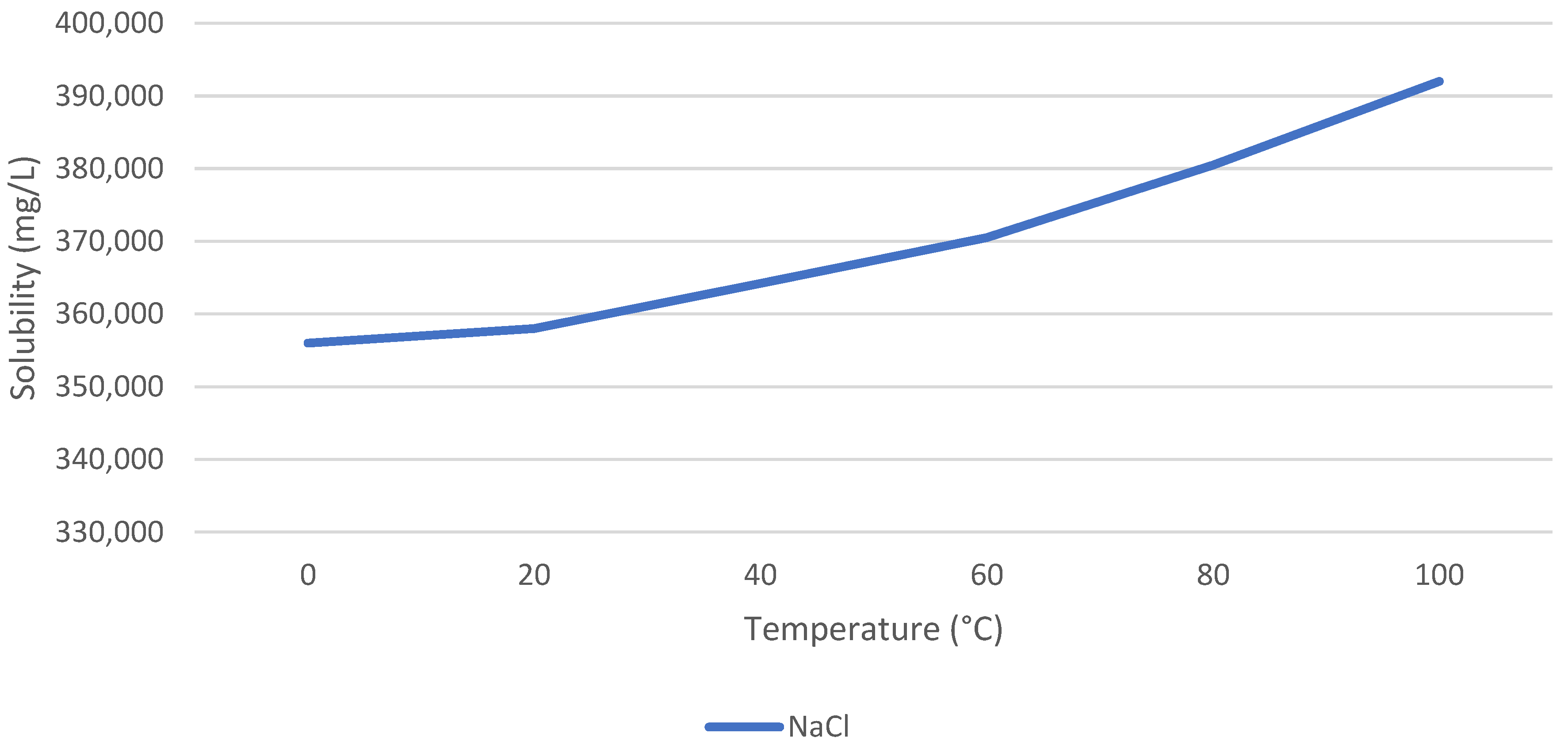
Figure 1 indicates the solubility of halite at different temperatures. As can be seen, the solubility stays relatively constant but slightly increases with temperature. Although halite has a high solubility, the high concentration of Na+ and Cl ions in the solution will lead to crystallization after concentration. Because halite has a neutral T–S behavior, the crystallization temperature must prevent the crystallization of other possible salts that would alter the purity of the crystals recovered.

3.1.4. Epsomite Crystallization

The solubility of epsomite increases with temperature and suddenly increases drastically above 55 °C, which makes it very soluble at high temperatures. This can be used to precipitate halite separately from epsomite.

3.2. Multi-Crystallization System

3.2.1. Crystallization Conditions

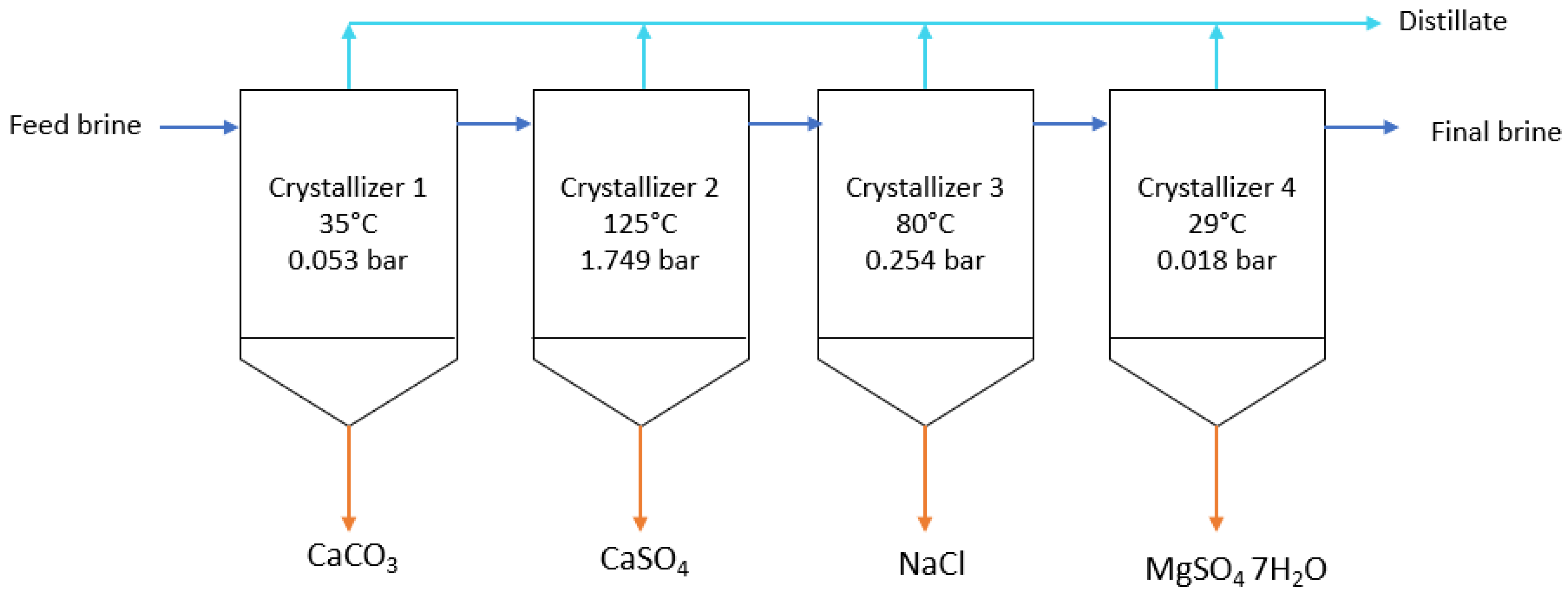
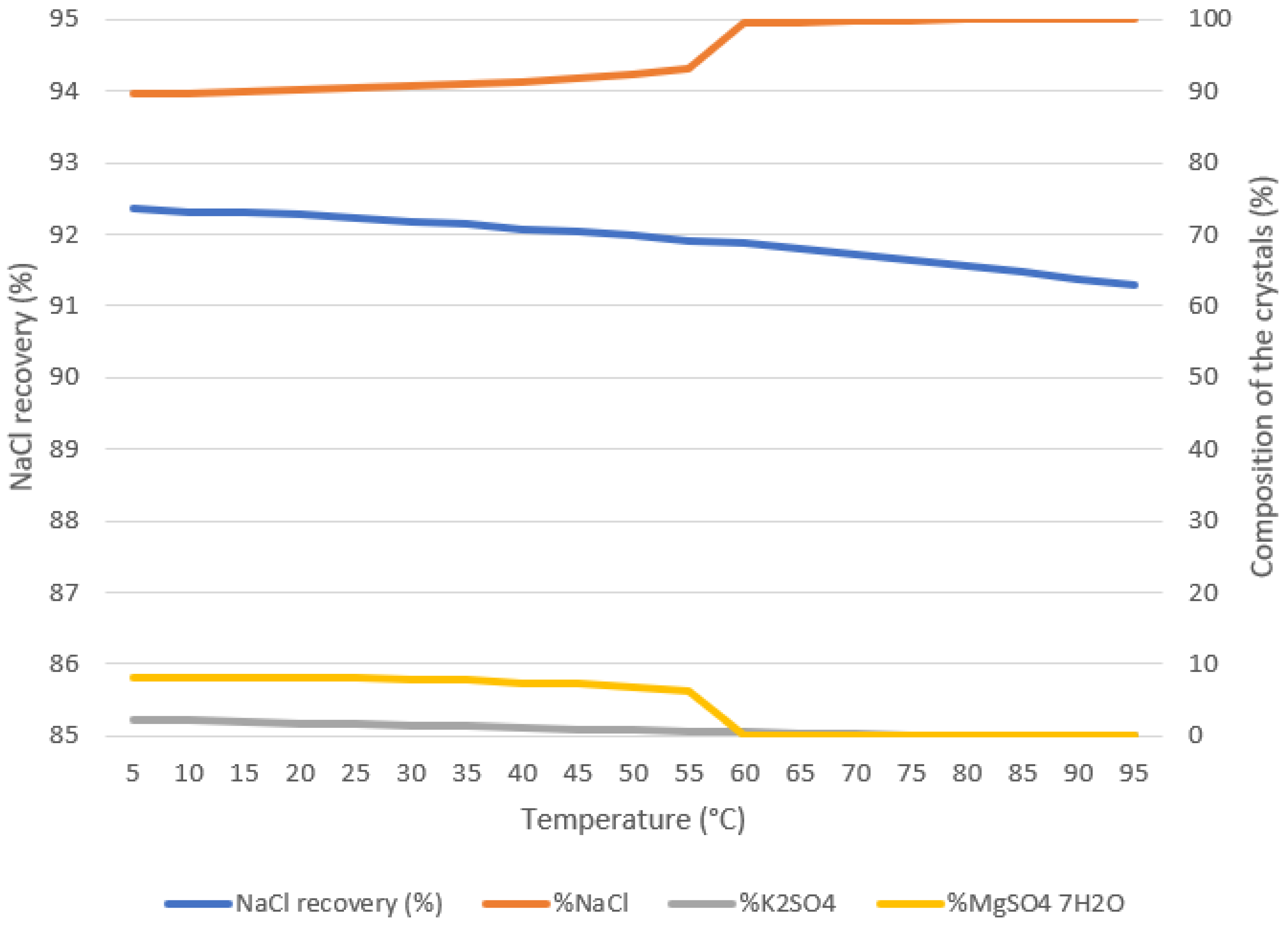
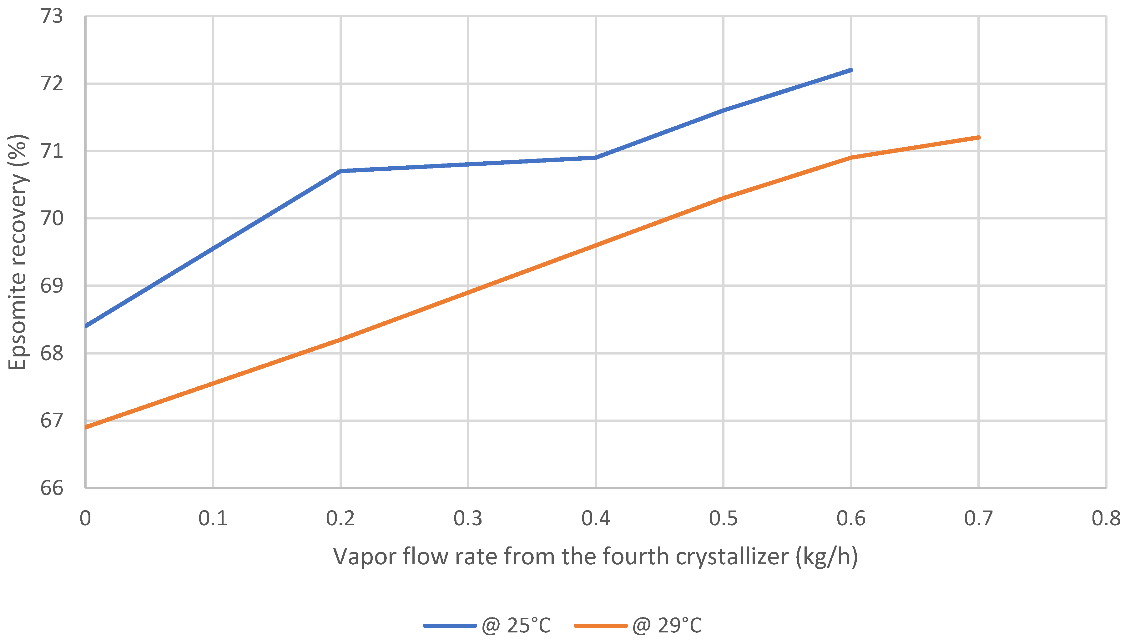
Figure 2 shows a schematic of the multi-crystallization system. The system consists of four crystallizers, each designed to specifically extract a pure crystal. The system was simulated on Aspen Plus to estimate the crystal production and purity. The chosen inputs for each crystallizer are its temperature and its vapor flow rate. For the first crystallizer, calcite precipitates at 35 °C, and the vapor flow rate is 450 kg/h to evaporate 47.6% of the water from the original brine because this concentrates the brine enough to achieve crystallization of calcite while maintaining the concentration of the remaining Ca2+ ions below the supersaturation limit of gypsum and anhydrite which is 1306 mg/L of Ca2+ ions. This allows for reaching high purity. The second crystallizer operates at 125 °C with a vapor flow rate of 402 kg/h to evaporate 42.5% of the water from the original brine to recover anhydrite. This high temperature is chosen because of the negative T–S behavior of anhydrite. This temperature also specifically favors the precipitation of anhydrite over gypsum and also allows an increase in vapor flow rate because the solubility of halite increases slightly with temperature. However, the precipitation of calcite from the remaining CO32− is inevitable, which reduces purity. The third crystallizer is designed to recover high-purity halite. At this point, several different salts can precipitate, including K 2 SO 4 and epsomite. Figure 3 reveals the evolution of halite recovery and purity from the third crystallizer at a vapor flow rate of 85 kg/h (8.99% water evaporated from the original brine) as a function of temperature. When increasing vapor removal, brine concentration increases which in turn increases halite recovery, but it also induces precipitation of other salts, especially K 2 SO 4 above 55 °C and epsomite below 55 °C. Reducing the temperature slightly increases halite recovery but also reduces purity due to K 2 SO 4 and epsomite precipitation. Epsomite starts to precipitate at 55 °C as expected due to its lower solubility. This means that in order to keep the same purity at a lower temperature, the vapor removal must be lowered as well to reduce the precipitation of other salts. However, because halite has a neutral T–S behavior, the recovery of halite is mostly dictated by vapor removal. As a result, lowering the temperature and vapor flow rate leads to lower recovery. The maximum purity and recovery are achieved at 80 °C and 85 kg/h vapor flow rate. Finally, the last crystallizer is designed to recover epsomite. Because epsomite has a positive T–S behavior, lowering the temperature allows for increased recovery. Figure 4 shows the evolution of the recovery of epsomite at 25 °C and 29 °C as a function of vapor flow rate. Reducing the temperature of the crystallizer increases recovery because of the positive T–S behavior of epsomite. Additionally, increasing vapor removal also increases recovery because it increases brine concentration. The maximum recovery at 25 °C and 29 °C are respectively 72.2% at 0.6 kg/h vapor flow rate and 71.1% at 0.7 kg/h vapor flow rate. This means crystallizer four evaporates a very small portion of water, equivalent to 0.07% of the water from the original brine. In both conditions, the purity is 40.7% because of the co-precipitation of MgCl 2 , K 2 SO 4 and carnallite. Other simulations performed at different vapor pressures and temperatures did not converge. However, it is expected that increasing the temperature will reduce recovery due to the positive T–S behavior of epsomite. However, considering the incoming brine from the third crystallizer is at 80 °C, choosing a higher temperature allows for reducing energy consumption from the cooling system. For this study, 29 °C is selected as the optimum temperature because operating at 25 °C does not increase recovery significantly enough. The separation of epsomite, MgCl 2 , K 2 SO 4 and carnallite is difficult because they all have positive T–S behaviors and are all in supersaturated conditions. In total, this system evaporates 99.2% of the original brine.

3.2.2. Energy Supply

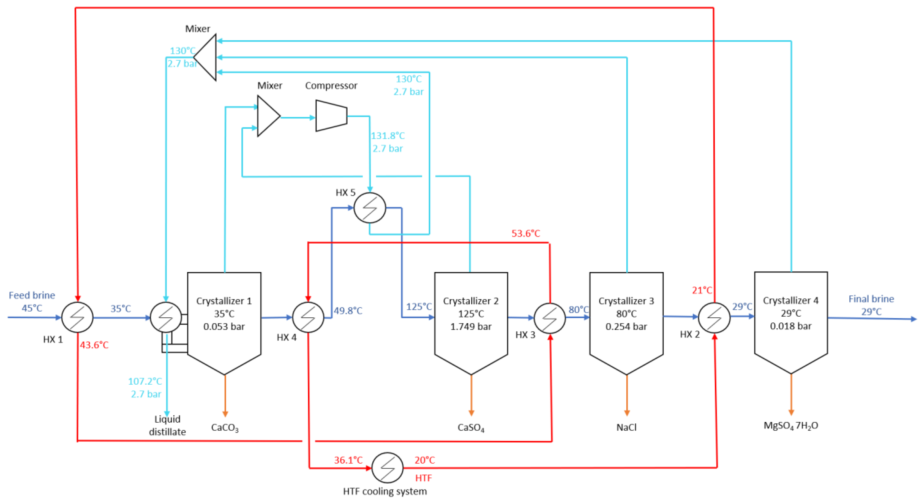
The energy consumption of the system can be reduced by recycling the heat between the different streams. Figure 5 demonstrates the schematic of the multi-crystallization system with the heat transfer fluid (HTF). Indeed, crystallizer four operates at 29 °C while the incoming feed from crystallizer three is at 80 °C. This means the system requires cooling. This can be performed by passing a cold HTF into the heat exchanger of crystallizer four. This HTF heats up slightly and then passes through a heat exchanger to pre-cool the initial brine entering the first crystallizer to 35 °C. The HTF heats up again and then passes through the heat exchanger of crystallizer three to cool down the incoming brine from crystallizer two from 125 °C to 80 °C. It heats up again, and it is then passed through the last heat exchanger to preheat the brine coming from crystallizer one to reduce the heating of crystallizer two. The HTF then cools down slightly and finally enters a cooling system which brings its temperature back to its original one of 20 °C. The heating of crystallizer two to 125 °C is performed by using a compressor which increases the temperature and the pressure of the vapor from crystallizer one mixed with that of crystallizer two to reach a flow rate and a temperature high enough to heat up the brine to 125 °C. This reduces energy consumption because once compressed to 2.7 bar, the vapor enters the heat exchanger and condenses at 130 °C and 2.7 bar, which releases latent heat of condensation coupled with sensible heat to the brine. In the simulation, 56% of the vapor has condensed in this heat exchanger (HX 5). Then this stream mixes with the vapor from the other crystallizers and is fed to the heat exchanger of crystallizer one to supply 301 kW of energy needed for evaporation. At this point, the final total distillate condenses completely and cools down to 107.2 °C. Reusing the vapor and its latent heat of condensation greatly reduces energy consumption.
Several temperatures and flow rates of the HTF were tested to maximize heat recovery, but the most feasible is a temperature of 20 °C and a flow rate of 418 kg/h. Increasing the temperature reduces pre-cooling of the initial brine while reducing temperature increases the energy consumption from the HTF cooling system and reduces preheating of the brine entering crystallizer two. Increasing the flow rate reduces preheating of the brine entering crystallizer two while reducing the flow rate reduces the pre-cooling of crystallizer one.
In addition to the HTF cooling system, the Aspen Plus simulation also predicts that crystallizers 2–4 also require additional cooling to extract the crystals. Indeed, crystallizers two, three, and four require, respectively, −13.5 kW, −84.1 kW, and −19 kW.

3.3. Conventional Concentrator–Crystallizer ZLD System

The considered conventional ZLD system is designed to recover mostly halite as per [27]. However, three different salts can precipitate before NaCl, including calcite ( CaCO 3 ), gypsum ( CaSO 4 · 2 H 2 O ) and anhydrite ( CaSO 4 ) due to their lower solubility. Because the aim is to recover mostly NaCl from the brine, a brine concentrator is used to evaporate a significant amount of water from the system to concentrate the solution to reach the supersaturation of NaCl. The precipitation of calcite inside the concentrator is not considered an issue because concentrators are coated with a layer preventing calcite scaling and also because the quantity of precipitating calcite is low. However, the precipitation of gypsum or anhydrite inside the concentrator can lead to important scaling that could damage or reduce the efficiency of the evaporator. For that reason, the concentrator is made to evaporate as much water as possible before exceeding the supersaturation limit for gypsum and anhydrite.
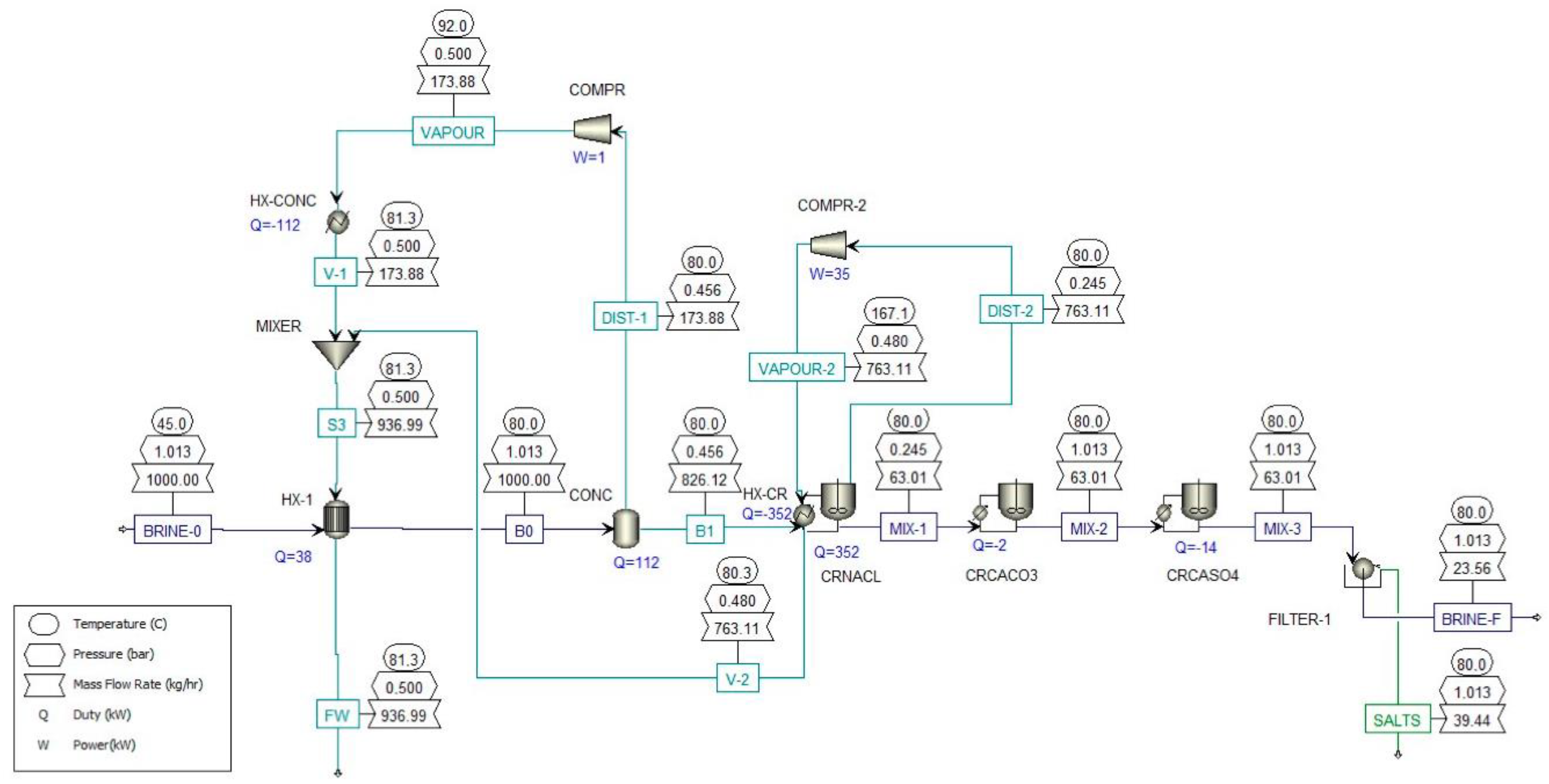
The optimal temperature of the crystallizer will decide the temperature of the concentrator because choosing a similar operating temperature allows to reduce heating requirements and thus lowers energy consumption. Similarly to the multi-crystallization system, the crystallizer is made to operate at 80 °C to reach high purity. Moreover, to minimize heating demand, the concentrator must also operate at 80 °C. At 80 °C, anhydrite is more stable than gypsum, so it will precipitate after concentration. The solubility of anhydrite at 80 °C corresponds to a concentration in Ca2+ of 870.5 mg/L and in SO42− of 2086.5 mg/L. Here calcium is the limiting reactant, so the brine in the concentrator must not exceed 870.5 mg/L of Ca2+. Considering the composition of the brine, this means the concentrator can remove 18.4% of the water from the brine before inducing anhydrite precipitation. Then the remaining brine is sent to the crystallizer, where 80.7% of the water from the original brine is removed. Figure 6 shows the flowsheet of the simulation of the system on Aspen Plus with the results from the different streams on the basis of 1000 kg/h of feed brine. Note that there are three crystallizers here, but they are simply here to calculate how much impurities would precipitate along with NaCl considering the software cannot handle several crystals to precipitate from one crystallizer. As can be seen, the concentrator should operate at 0.456 bar while the crystallizer should operate at 0.245 bar meaning vacuum pumps are required. The power required by the concentrator to evaporate 18.4% of water is 112 kWth, while the power required to evaporate 80.7% of the original water from the crystallizer is 352 kWth. However, this power can be supplied by recycling the heat from the vapor produced by the concentrator and the crystallizer through two compressors.
Indeed, if we use compressors, we increase the pressure and temperature of the vapor. When the vapor passes through the evaporator and the crystallizer again (in the shell side), it will condense because the temperature will decrease until it reaches the corresponding temperature of condensation at the chosen compression pressure, and so this means there will be latent heat transfer which increases thermal power delivered. The vapor from the concentrator passes through a 0.74 kW compressor which raises its temperature and pressure to 92 °C and 0.5 bar before it is sent through the shell side of the concentrator to supply 112 kWth, where it will partially condense (99.6% liquid fraction) and provide latent and sensible heat to evaporate water in the concentrator. On the crystallizer side, the vapor passes through a 35 kW compressor to increase its temperature and pressure to 167 °C and 0.48 bar so it can supply 352 kWth inside the heat exchanger of the crystallizer to evaporate the water as the vapor partially condenses (65% liquid) at 80.3 °C and gives off latent and sensible heat. So recovering latent heat reduces energy consumption. Indeed, with the compressors, the total energy consumption is 37.1 kWhe/m3, while without compressors, the energy needed is 463.7 kWhth/m3. Therefore, compressors reduce energy consumption. This is also a fact that has been proven in many different studies: [28,29,30,31,32,33,34,35,36], and it is also a concept conventionally used by Suez [37]. The condensates then mix and pass inside a heat exchanger to preheat the initial brine from 45 °C to 80 °C. The water coming out of the pre-heater condenses partially (77.5% liquid fraction) and comes at 81.3 °C and 0.5 bar.

3.4. Economic Analysis

Table 5 lists the different equations used to calculate the costs of the different components with B the feed brine flow rate entering the blocks. Centrifuge and vacuum filters are commonly used to extract salts and other solids from various streams. An industrial vacuum drum filter applicable to separate waste gypsum from industrial wastewater costs between 8000–10,000 USD/unit [38]. The capacity of such a filter is not given, so the cost of the filters in this study is assumed at 1000 USD/(kg/h) of produced salts ( S ) in Equation (6). The cost of the heat exchangers is taken at 13.3 USD/kW [39]. The cost of the compressor is taken at 1000 USD/kW [40]. The cost of the HTF cooling system is assumed at 1500 USD/kW [41]. The coefficient of performance (COP) of the cooling system is assumed at three [41], meaning that for each 3 kW of thermal energy delivered, the cooling system consumes 1 kW of electricity. The cost of a pump is given in Equation (10) with P p u m p   the electrical power of the pump in kW. The standard electricity price in Oman in December 2021 was 0.148 USD/kWhe for businesses, and this value is assumed for this study in Equation (18) [42]. Equation (23) defines the levelized cost of salt (LCOS) for each of the different salts. The average price of water in Oman in 2022 is 1.100 OMR/m3 or 2.85 USD/m3 [43]. The electrical power required by the brine pump, freshwater pump, HTF pump and vacuum pumps are assumed at 0.5 kW/(kg/s). For this study, the prices of the different salts are taken as their average market price for simplicity: 0.2315 USD/kg for calcite, 0.016 USD/kg for anhydrite, 0.17 USD/kg for halite and 0.1805 USD/kg for epsomite [44]. A degradation rate of 0.2% per year is considered. Table 6 lists the economic assumptions. Table 7 summarizes the industrial uses of the different salts and their current average market price taken from [44]. The prices of salts depend on various factors including the grade quality and the quantity.

3.5. Simulation Results

3.5.1. Multi-Crystallization System Results

Table 8 shows the production results of the simulation of the multi-crystallization system at a scale of 1000 kg/h of feed brine. Without energy recovery, the system would require thermal energy consumption of 678 kWth, which is close to the value of 710 kWth found by [21], which reinforces the results. Additionally, the operating temperatures of the crystallizers in this study are close to those in [21]. Table 9 shows the composition of the salts recovered from crystallizer four. As can be seen, the purity of epsomite is very low at 40.7% because other salts co-precipitate, including MgCl 2 , NaCl , K 2 SO 4 and carnallite. The separation of those salts is difficult because they all have positive T–S behavior and are all in a supersaturation state. For that reason, the selling price of epsomite is taken as 0 because of its very low purity. Table 10 shows the energy consumption results. Table 11 shows the economic results. The system can generate USD79,313/year in revenue, with water accounting for 29.52% of the income, calcite 0.25%, anhydrite 0.38%, and halite 69.85%. The results estimate that the system has high electricity cost which accounts for 68.7% of the annual expenses. The levelized costs are high with 13.79 USD/m3 for water, 131.40 USD/kg for calcite, 6.04 USD/kg for anhydrite, 0.35 for halite and 2.79 for epsomite.

3.5.2. Conventional ZLD System Results

Table 12 indicates the production results of the simulation of the conventional ZLD system at a scale of 1000 kg/h of feed brine, and Table 13 shows the composition of the recovered salts. Table 14 shows the energy consumption results. Table 15 shows the economic results. The selling price of halite is assumed proportional to its purity. Considering the average price of 99.9% pure halite is 0.17 USD/kg, then the price of 94.3%-pure halite is 0.16 USD/kg. The economic results show that the conventional system is profitable after 7.69 years and can generate USD78,821 in revenue, with salts and water accounting, respectively, for 70.1% and 29.9% of the income. The LCOW is 7.85 USD/m3, and the LCO halite is 0.20 USD/m3, which is lower than the multi-crystallization system. The system also has a lower energy consumption of 37.09 kWhe/ton of feed brine.

4. Discussion

The production of calcite from the multi-crystallization system is minimal compared to that of other salts, but its extraction allows the production of high-purity anhydrite and halite. The purity of epsomite is very low due to the co-precipitation of other salts, which have positive T–S behavior. This low purity prevents the crystals from crystallizer four from being directly sold. Instead, they would need to be post-processed to separate the different salts, which could then be sold to different industries, including cement manufacturing. Re-dissolution and re-precipitation could be a solution to extract each crystal separately. The integration of a compressor and an HTF allows reducing energy consumption by 81.88%. Future research should look at the application of solar cooling systems and the production of electricity by renewable sources to suggest a sustainable and auto-sufficient process that could lower electricity costs and allow profitability. The produced distillate from this system is still hot at 107.2 °C, which could be used to supply energy to a thermal desalination system such as a multi-effect distillation (MED) process using the hot distillate as the HTF for the first effect. This combined system would operate as a potential cycle. This multi-crystallization system is not competitive with the conventional ZLD system because of the high electricity cost leading to high LCOW and LCOSs. However, integrating renewable energy technology such as photovoltaic (PV) or solar thermal to produce electricity could lower the cost of electricity and allow profitability. Moreover, scale-up of the system to a large industrial scale would reduce the levelized costs and could reach profitability. Additionally, the COP of the cooling system in this study was assumed at three, but cooling systems with better efficiency exist and could be used here to reduce energy consumption further. Nevertheless, the proposed system can reach ZLD with high water recovery and brine reduction, which, when applied to desalination plants, would significantly reduce environmental damage. The HTF system was designed to reduce energy consumption and reach the desired operating temperatures for each crystallizer. However, future research should look at the efficiency of the system through a bench analysis.

5. Conclusions

The proposed multi-crystallization system can recover calcite, anhydrite, halite, epsomite, and other salts and can be used for desalination plants to achieve ZLD and resource recovery. The recovered salts could be easily used in the cement industry as a sustainable source of material, especially if the process utilizes renewable energies. The system achieves low energy consumption of 60.72 kWhe/ton of feed brine thanks to the integration of a novel HTF and compressor heat recovery system and requires mostly cooling. It can achieve high water recovery of 99.2% and high brine mass reduction of 98.9%. The recovery of liquid water and salts accounts for additional revenues, with halite and water accounting, respectively, for 69.85% and 29.52% of the income. Calcite and anhydrite production is very low and leads to a low contribution to revenue. The LCOW is 13.79 USD/m3 as opposed to 7.85 USD/m3 for the conventional ZLD system. However, the multi-crystallization system could reach profitability if the system can lower its annual electricity cost, notably by using renewable energies. The conventional ZLD system is still more profitable, but the multi-crystallization system offers higher purity crystals and the possibility to supply valuable salts to industries, possibly cutting the need for traditional mineral extraction from mines which is responsible for significant pollution.

Author Contributions

Conceptualization, K.P. (Kumar Patchigolla) and N.A.M.; methodology, K.P. (Kristofer Poirier); software, K.P. (Kristofer Poirier); validation, K.P. (Kristofer Poirier); investigation, K.P. (Kristofer Poirier), K.P. (Kumar Patchigolla) and N.A.M.; writing-original draft preparation, K.P. (Kristofer Poirier); supervision, K.P. (Kumar Patchigolla) and N.A.M.; review, K.P. (Kumar Patchigolla) and N.A.M.; project administration, K.P. (Kumar Patchigolla) and N.A.M. All authors have read and agreed to the published version of the manuscript.

Funding

This work has received funding from the European Union’s Horizon 2020 research and innovation programme under grant agreement No. 101022686 (DESOLINATION) and 869496 (REWAISE via Solar Water Plc) and from German University of Technology in Oman.

Data Availability Statement

The authors confirm that the data supporting the findings of this study are available within the article.

Acknowledgments

We would like to thank GUtech and Cranfield University for their partnership and collaboration that support this study.

Conflicts of Interest

The authors declare no conflict of interest.

References

  1. Jones, E.; Qadir, M.; van Vliet, M.T.H.; Smakhtin, V.; Kang, S.M. The State of Desalination and Brine Production: A Global Outlook. Sci. Total Environ. 2019, 657, 1343–1356. [Google Scholar] [CrossRef]
  2. Suez Barka II Seawater Reverse Osmosis Desalination Plant (Oman). Available online: https://www.suezwaterhandbook.com/case-studies/desalination/Barka-II-seawater-reverse-osmosis-desalination-plant-Oman (accessed on 3 July 2022).
  3. Choi, Y.; Naidu, G.; Nghiem, L.D.; Lee, S.; Vigneswaran, S. Membrane Distillation Crystallization for Brine Mining and Zero Liquid Discharge: Opportunities, Challenges, and Recent Progress. Environ. Sci. Water Res. Technol. 2019, 5, 1202–1221. [Google Scholar] [CrossRef]
  4. Balis, E.; Griffin, J.C.; Hiibel, S.R. Membrane Distillation-Crystallization for Inland Desalination Brine Treatment. Sep. Purif. Technol. 2022, 290, 120788. [Google Scholar] [CrossRef]
  5. Szilagyi, B.; Majumder, A.; Nagy, Z.K. Fundamentals of Population Balance Based Crystallization Process Modeling. In Handbook of Continuous Crystallization; The Royal Society of Chemistry: London, UK, 2020; pp. 51–101. ISBN 9781788013581. [Google Scholar]
  6. Ji, G.; Wang, W.; Chen, H.; Yang, S.; Sun, J.; Fu, W.; Huang, Z.; Yang, B. A Novel Membrane-Promoted Crystallization Process Integrating Water Recovery and Salt Production for Brine Management. Chem. Eng. J. 2022, 430, 133022. [Google Scholar] [CrossRef]
  7. Ji, G.; Wang, W.; Chen, H.; Yang, S.; Sun, J.; Fu, W.; Yang, B.; Huang, Z. Sustainable Potassium Chloride Production from Concentrated KCl Brine via a Membrane-Promoted Crystallization Process. Desalination 2022, 521, 115389. [Google Scholar] [CrossRef]
  8. Vassallo, F.; Mogante, C.; Battaglia, G.; La Corte, D.; Micari, M.; Cipollina, A.; Tamburini, A.; Micale, G. A Simulation Tool for Ion Exchange Membrane Crystallization of Magnesium Hydroxide from Waste Brine. Chem. Eng. Res. Des. 2021, 173, 193–205. [Google Scholar] [CrossRef]
  9. Mene, N.R.; Murthy, Z.V.P. Recovery of Pure Water and Crystalline Products from Concentrated Brine by Using Membrane Distillation Crystallization. Sep. Sci. Technol. 2019, 54, 396–408. [Google Scholar] [CrossRef]
  10. Yadav, A.; Patel, R.V.; Vyas, B.G.; Labhasetwar, P.K.; Shahi, V.K. Recovery of CaSO4 and NaCl from Sub-Soil Brine Using CNT@MOF5 Incorporated Poly(Vinylidene Fluoride-Hexafluoropropylene) Membranes via Vacuum-Assisted Distillation. Colloids Surfaces A Physicochem. Eng. Asp. 2022, 645, 128918. [Google Scholar] [CrossRef]
  11. Choi, Y.; Naidu, G.; Lee, S.; Vigneswaran, S. Recovery of Sodium Sulfate from Seawater Brine Using Fractional Submerged Membrane Distillation Crystallizer. Chemosphere 2020, 238, 124641. [Google Scholar] [CrossRef]
  12. Lai, X.; Xiong, P.; Zhong, H. Extraction of Lithium from Brines with High Mg/Li Ratio by the Crystallization-Precipitation Method. Hydrometallurgy 2020, 192, 105252. [Google Scholar] [CrossRef]
  13. Cha-umpong, W.; Li, Q.; Razmjou, A.; Chen, V. Concentrating Brine for Lithium Recovery Using GO Composite Pervaporation Membranes. Desalination 2021, 500, 114894. [Google Scholar] [CrossRef]
  14. Vassallo, F.; La Corte, D.; Cancilla, N.; Tamburini, A.; Bevacqua, M.; Cipollina, A.; Micale, G. A Pilot-Plant for the Selective Recovery of Magnesium and Calcium from Waste Brines. Desalination 2021, 517, 115231. [Google Scholar] [CrossRef]
  15. Yadav, A.; Singh, K.; Panda, A.B.; Labhasetwar, P.K.; Shahi, V.K. Membrane Distillation Crystallization for Simultaneous Recovery of Water and Salt from Tannery Industry Wastewater Using TiO2 Modified Poly (Vinylidene Fluoride-Co-Hexafluoropropylene) Nanocomposite Membranes. J. Water Process. Eng. 2021, 44, 102393. [Google Scholar] [CrossRef]
  16. Kim, J.; Kim, J.; Hong, S. Recovery of Water and Minerals from Shale Gas Produced Water by Membrane Distillation Crystallization. Water Res. 2018, 129, 447–459. [Google Scholar] [CrossRef]
  17. Chen, Q.; Burhan, M.; Shahzad, M.W.; Ybyraiymkul, D.; Akhtar, F.H.; Li, Y.; Ng, K.C. A Zero Liquid Discharge System Integrating Multi-Effect Distillation and Evaporative Crystallization for Desalination Brine Treatment. Desalination 2021, 502, 114928. [Google Scholar] [CrossRef]
  18. Von Eiff, D.; Wong, P.W.; Gao, Y.; Jeong, S.; An, A.K. Technical and Economic Analysis of an Advanced Multi-Stage Flash Crystallizer for the Treatment of Concentrated Brine. Desalination 2021, 503, 114925. [Google Scholar] [CrossRef]
  19. Luo, X.; Li, X.; Wei, C.; Deng, Z.; Liu, Y.; Li, M.; Zheng, S.; Huang, X. Recovery of NaCl and Na2SO4 from High Salinity Brine by Purification and Evaporation. Desalination 2022, 530, 115631. [Google Scholar] [CrossRef]
  20. Ziegenheim, S.; Szabados, M.; Konya, Z.; Kukovecz, A.; Palinko, I.; Sipos, P. Differential Precipitation of Mg(OH)2 from CaSO4×2H2O Using Citrate as Inhibitor—A Promising Concept for Reagent Recovery from MgSO4 Waste Streams. Molecules 2020, 21, 5012. [Google Scholar] [CrossRef]
  21. Wu, L.; Sun, T.; Hu, Y. Simulation and Optimization of Salt-Production Process from Desalination Brine. Chem. Eng. Trans. 2017, 61, 1735–1740. [Google Scholar] [CrossRef]
  22. Ahmed, M.; Shayya, W.H.; Hoey, D.; Al-Handaly, J. Brine Disposal from Reverse Osmosis Desalination Plants in Oman and the United Arab Emirates. Desalination 2001, 133, 135–147. [Google Scholar] [CrossRef]
  23. Hussein, A.A.; Zohdy, K.M.; Abdelkreem, M. Seawater Bittern a Precursor for Magnesium Chloride Separation: Discussion and Assessment of Case Studies. Int. J. Waste Resour. 2017, 7, 1000267. [Google Scholar] [CrossRef]
  24. Saltwork Consultants Pty Ltd. Marine Brine—Modern. Available online: https://saltworkconsultants.com/marine-brine-modern/ (accessed on 4 July 2022).
  25. Al-Jibbouri, S.; Strege, C.; Ulrich, J. Crystallization Kinetics of Epsomite Influenced by PH-Value and Impurities. J. Cryst. Growth 2002, 236, 400–406. [Google Scholar] [CrossRef]
  26. Solubility Table of Compounds in Water at Temperature. Available online: https://www.sigmaaldrich.com/FR/fr/support/calculators-and-apps/solubility-table-compounds-water-temperature (accessed on 20 June 2022).
  27. Alspach, B.; Juby, G. Cost-Effective ZLD Technology for Desalination Concentrate Management. J. AWWA 2018, 11, 307–310. [Google Scholar] [CrossRef]
  28. Castro, M.; Alcanzare, M.; Esparcia, E.; Ocon, J. A Comparative Techno-Economic Analysis of Different Desalination Technologies in Off-Grid Islands. Energies 2020, 13, 2261. [Google Scholar] [CrossRef]
  29. Schwantes, R.; Chavan, K.; Winter, D.; Felsmann, C.; Pfafferott, J. Techno-Economic Comparison of Membrane Distillation and MVC in a Zero Liquid Discharge Application. Desalination 2018, 428, 50–68. [Google Scholar] [CrossRef] [Green Version]
  30. Xiao, H.F.; Shao, D.D.; Wu, Z.L.; Peng, W.B.; Akram, A.; Wang, Z.Y.; Zheng, L.J.; Xing, W.; Sun, S.P. Zero Liquid Discharge Hybrid Membrane Process for Separation and Recovery of Ions with Equivalent and Similar Molecular Weights. Desalination 2020, 482, 114387. [Google Scholar] [CrossRef]
  31. Najafi, F.T.; Alsaffar, M.M.; Schwerer, S.C.; Brown, N.; Ouedraogo, J. Environmental Impact Cost Analysis of Multi-Stage Flash, Multi-Effect Distillation, Mechanical Vapor Compression, and Reverse Osmosis Medium-Size Desalination Facilities. In Proceedings of the 2016 ASEE Annual Conference & Exposition, New Orleans, LA, USA, 26–28 June 2016. [Google Scholar] [CrossRef] [Green Version]
  32. Eisavi, B.; Nami, H.; Yari, M.; Ranjbar, F. Solar-Driven Mechanical Vapor Compression Desalination Equipped with Organic Rankine Cycle to Supply Domestic Distilled Water and Power—Thermodynamic and Exergoeconomic Implications. Appl. Therm. Eng. 2021, 193, 116997. [Google Scholar] [CrossRef]
  33. Farahat, M.A.; Fath, H.E.S.; El-Sharkawy, I.I.; Ookawara, S.; Ahmed, M. Energy/Exergy Analysis of Solar Driven Mechanical Vapor Compression Desalination System with Nano-Filtration Pretreatment. Desalination 2021, 509, 115078. [Google Scholar] [CrossRef]
  34. Cipolletta, G.; Lancioni, N.; Cagri, A.; Eusebi, A.L.; Fatone, F. Brine Treatment Technologies towards Minimum/Zero Liquid Discharge and Resource Recovery: State of the Art and Techno-Economic Assessment. J. Envrion. Manag. 2021, 300, 113681. [Google Scholar] [CrossRef]
  35. Giwa, A.; Dufour, V.; Al Marzooqi, F.; Al Kaabi, M.; Hasan, S.W. Brine Management Methods: Recent Innovations and Current Status. Desalination 2017, 407, 1–23. [Google Scholar] [CrossRef]
  36. Yaqub, M.; Lee, W. Zero-Liquid Discharge (ZLD) Technology for Resource Recovery from Wastewater: A Review. Sci. Total Environ. 2019, 681, 551–563. [Google Scholar] [CrossRef]
  37. Zero Liquid Discharge (ZLD) Technology—Wastewater Treatment|SUEZ. YouTube. 2018. Available online: https://youtu.be/aQsK9VK6L5k (accessed on 19 July 2022).
  38. JX Filtration JX5-1.6 Vacuum Drum Filter. Available online: https://shop.filtrationchina.com/products/vacuum-drum-filter?variant=39865020153930&currency=USD&utm_medium=product_sync&utm_source=google&utm_content=sag_organic&utm_campaign=sag_organic&gclid=CjwKCAjw5s6WBhA4EiwACGncZYuH4yfLu_d_cXk33ltZSuuyzRiKPHhpd_L4W (accessed on 17 July 2022).
  39. Loutatidou, S.; Arafat, H.A. Techno-Economic Analysis of MED and RO Desalination Powered by Low-Enthalpy Geothermal Energy. Desalination 2015, 365, 277–292. [Google Scholar] [CrossRef]
  40. Apt, J.; Newcomer, A.; Lave, L.B.; Douglas, S.; Dunn, L.M. An Engineering-Economic Analysis of Syngas Storage. U.S. Department of Energy, The National Energy Technology Laboratory: Pittsburgh, PA, USA, 2008; Volume 143. [Google Scholar]
  41. Alahmer, A.; Ajib, S. Solar Cooling Technologies: State of Art and Perspectives. Energy Convers. Manag. 2020, 214, 112896. [Google Scholar] [CrossRef]
  42. Global Petrol Prices Oman Electricity Prices. December 2021. Available online: https://www.globalpetrolprices.com/Oman/electricity_prices/ (accessed on 17 July 2022).
  43. WAF News Agency Oman Restructures Water and Electricity Tariffs. Available online: https://www.google.fr/search?q=average+price+of+water+oman&sxsrf=ALiCzsYQXbz0eI-zAOrpmjUlnkyGb3aEjQ%3A1658068666256&ei=uh7UYpmGD_mE9u8PtaGt0AY&ved=0ahUKEwiZy_WOk4D5AhV5gv0HHbVQC2oQ4dUDCA4&uact=5&oq=average+price+of+water+oman&gs_lcp=Cgdnd3Mtd2l6EAMyCgghEB (accessed on 17 July 2022).
  44. Indiamart. Available online: https://www.indiamart.com/ (accessed on 19 July 2022).
  45. Tsai, J.H.; Macedonio, F.; Drioli, E.; Giorno, L.; Chou, C.Y.; Hu, F.C.; Li, C.L.; Chuang, C.J.; Tung, K.L. Membrane-Based Zero Liquid Discharge: Myth or Reality? J. Taiwan Inst. Chem. Eng. 2017, 80, 192–202. [Google Scholar] [CrossRef]
  46. Christ, A.; Rahimi, B.; Regenauer-lieb, K.; Tong, H. Techno-Economic Analysis of Geothermal Desalination Using Hot Sedimentary Aquifers: A Pre-Feasibility Study for Western Australia. Desalination 2017, 404, 167–181. [Google Scholar] [CrossRef]
  47. Selina Wamucii Oman Table Salt Prices. Available online: https://www.selinawamucii.com/insights/prices/oman/table-salt (accessed on 19 July 2022).
Figure 1. Influence of temperature on the solubility of NaCl [26].
Separations 09 00295 g001
Figure 2. Schematic of the multi-crystallization system concept.
Separations 09 00295 g002
Figure 3. Evolution of halite recovery and crystal composition from the third crystallizer as a function of temperature with a vapor flow rate of 85 kg/h.
Separations 09 00295 g003
Figure 4. Evolution of the recovery of epsomite from the fourth crystallizer as a function of vapor flow rate at 25 °C and 29 °C.
Separations 09 00295 g004
Figure 5. Schematic of the multi-crystallization with the addition of a HTF for heat recovery.
Separations 09 00295 g005
Figure 6. Flowsheet of simulation of the concentrator–crystallizer system on Aspen Plus for a scale of 1000 kg/h of feed brine.
Separations 09 00295 g006
Table 1. Examples of solutes with different T–S behaviors [3,4].
T–S Behavior
PositiveNegativeNeutral
MgSO 4 · 7 H 2 O
KCl
Na 2 SO 4 · 10 H 2 O
MgCl 2
Carnallite
NaNO 3
CaCO 3
CaCl 2 CaSO 4
Na 2 SO 4 NaCl
Pb ( NO 3 ) 2 Ca ( OH ) 2 CaSO 4 · 2 H 2 O
Kainite
KNO 3 NH 3
K 2 Cr 2 O 7
KClO 3
Table 2. Crystallization conditions and simulations results for the multi-crystallization system for desalination brines [21].
Crystallizer12345
SaltsMg(OH)2CaSO4NaClKClCaCl2
Crystallization temperature (°C)251186070139
Crystallization pressure (bar)1.011.370.120.11.01
Crystal production (kg/h)5.766.7845.942.9812.30
Purity (%)10010099.998.298.2
Recovery (%)99.699.196.1100100
Total energy consumption without energy recovery (kW)710.5
Total energy consumption with direct preheating (kW)94.8
Total energy consumption with compressor preheating (kW)90.1
Table 3. Composition of the brine used in this study along with the composition of seawater and brines from three different desalination plants in UAE.
This Study (Average)Qidfa IQidfa IIJabal Al−Dhana
ParametersSeawaterBrineSeawaterBrineSeawaterBrineSeawaterBrine
Ca2+ (mg/L)544.33702.33464617533730636760
Mg2+ (mg/L)18002350164021501620224021402660
Na+ (mg/L)12,766.6716 20011,90015,10012,20015,80014,20017,700
K+ (mg/L)605.33840.67574767581805661950
Sr2+ (mg/L)7.289.704.567.197.2911.5010.0010.40
SiO2 (mg/L)5.737.361.071.0715.0419.941.071.07
Si4+ (mg/L)2.683.440.500.507.039.320.500.50
Cations Total (me/L)746.12954.63690.44884.18705.47928.65842.451051.07
pH7.596.707.876.767.066.977.836.38
HCO3 (mg/L)124.67119.67136117100125138117
Cl (mg/L)24 57732,46123,14930,54023,48432,00427,09834,839
SO42− (mg/L)3029.674344.33278739313181450031214602
N (mg/L)0.530.730.500.700.500.700.600.80
NO3 (mg/L)2.673.172.203.003.303.102.503.40
F (mg/L)1.301.771.502.100.600.901.802.30
Anions Total (me/L)758.551008.29713.40945.46730.43998.67831.811080.73
E.C. (mS/cm)59,24377,46655,70073,30056,13078,00065,90081,100
Ion balance−0.91−2.79−1.64−3.35−1.74−3.630.64−1.39
SAR (me/L)59.3965.9458.2264.4559.3565.4260.5967.95
SER (me/L)74.5173.8574.9774.2975.2374.0173.3273.25
Langelier index (me/L)0.820.011.100.010.150.301.20−0.28
Ryzner index (me/L)5.956.685.676.736.766.375.436.93
TDS (mg/L)43,39856,97440,59253,17741,66156,15847,94161,587
Ions Total (mg/L)43,45957,03340,65853,23541,71056,22048,00961,645
Alkalinity total (mg/L)10298111968210211396
Total hardness (mg/L)878511,449792210,409801511,06710,41812,871
Fe (mg/L)0.240.350.220.330.220.350.270.37
Mn (mg/L)0.050.070.050.060.060.070.050.07
Cu (mg/L)0.200.200.500.500.050.050.050.05
Zn (mg/L)0.200.200.500.500.050.050.050.05
Cr (mg/L)0.350.200.500.500.500.050.050.05
Table 4. Influence of other compounds on the solubility of epsomite, adapted from [25].
SaltEffect on SolubilityEffect on Growth Rate
NaCl+
KCl=
MgCl2=
K2SO4+
NaOH+
H2SO4
+ increase, − decrease, = no effect.
Table 5. Economic analysis equations.
ComponentEquationEquation NumberReference
Brine concentrator cost (USD) C c o n c = 3100 × B ( m 3 day ) (4)[45]
Single crystallizer cost (USD) C c r y s t = 4000 × B ( m 3 day ) (5)[45]
Single filter cost (USD/unit) C f i l t e r = 1000 × S ( kg h ) (6)[38]
Heat exchanger cost (USD) C H X = 13.3 × Q ( kW ) (7)[39]
Compressor cost (USD) C c o m p = 1000 × W ( kW ) (8)
Cooling system cost (USD) C c o o l = 1500 × Q ( kW ) (9)
Pump cost (USD) C p u m p = 12,434 ( P p u m p × 1.34 ) 0.5 (10)[46]
Direct capital cost (USD) C D C = Σ   C i (11)
Indirect capital cost (USD) C I C = 0.10 × C D C (12)[17]
Total CAPEX CAPEX = C D C + C I C (13)
Amortization factor a = i   ×   ( i   +   1 ) t ( i   +   1 ) t 1 (14)
Amortized CAPEX (USD/year) CAPEX a m o r t i z e d = a × CAPEX (15)
Electrical power of cooling system P c o o l i n g , e l e c t r i c = Q c o o l i n g , t h e r m a l 3 (16)
Total electrical power (kW) P tot = P pumps + P comp + P cooler (17)
Electricity cost (USD/year) O & M e l e c = 0.148 × P t o t × hours year (18)
Labour cost (USD/year) O & M l a b o u r = 0.03   USD / m 3 × B ( m 3 year ) (19)[17]
Maintenance and replacement cost (USD/year) O & M r e p l a c e = 0.02   USD / m 3 day × B ( m 3 day ) (20)[17]
OPEX (USD/year) OPEX = O & M e l e c + O & M l a b o u r + O & M r e p l a c e (21)
LCOW (USD/m3) L C O W = CAPEX a m o r t i z e d   +   OPEX P r o d a n n u a l ,   w a t e r (22)
LCOS (USD/ton) L C O S = CAPEX a m o r t i z e d   +   OPEX P r o d a n n u a l ,   s a l t   i (23)
Revenue (USD/year) Revenue = 2.85 ( USD m 3 ) × Water Prod annual ( m 3 year )   +   Σ Price salt i ( USD ton ) × Prod annual , salt i ( ton year ) (24)
Annual cash flow (USD/year) Cash flow ( year 0 ) = CAPEX Cash flow ( year i ) = Revenue OPEX (25)
Payback period (years) P a y b a c k = CAPEX A n n u a l   c a s h   f l o w s (26)
Thermal SEC per m3 of feed brine (kWhth/ton) S E C t h = T o t a l   t h e r m a l   p o w e r   ( kW ) B ( ton / h ) (27)
Electrical SEC per m3 of feed brine (kWhe/ton) SEC e = Total electric power   ( kW ) B ( ton / h ) (28)
Table 6. Economic assumptions.
ParameterValueUnit
Interest rate0.05
Lifespan25years
Hours of operation per year8760h/year
Water price2.85USD/m3
Calcite price0.2315USD/kg
Anhydrite price0.016USD/kg
Halite price0.17USD/kg
Epsomite price0.1805USD/kg
Degradation rate annual0.998
COP of HTF cooling system3
Table 7. Industrial applications of the different recoverable salts from brines.
NameFormulaApplicationsMarket Price (USD/kg)
Calcite CaCO 3 Cement and concrete industry, iron purification, oil drilling, sugar refining, chalk, paint, ceramic glaze, medicine, agriculture, flue gas desulfurization.0.023–0.44
Gypsum CaSO 4 · 2 H 2 O Cement and concrete industry, construction industry, chalk, fertilizer, agricultural soil conditioning, food industry.0.016
Halite NaCl Food industry, agriculture, chemical industries, fire extinguishers, cleansers, ion-exchange resins, road de-icing, oil and gas well drilling, textile industry, pulp and paper industry, rubber manufacturing, soil foundation, gas welding.0.16–0.18
[47]
Sylvite KCl Fertilizers, medicine, table salt, food industry, soaps, oil and gas well completion, water softener, glass industry, gas welding of metals.
Epsomite MgSO 4 · 7 H 2 O Cement preparation by reaction with MgO, medicine, agriculture, food industry.0.081–0.28
Brucite Mg ( OH ) 2 Cement and concrete industry, medicine, food industry, wastewater treatment.
Magnesium chloride MgCl 2 Dust and erosion control, catalysts, road de-icing, food industry, horticulture.
Mirabilite Na 2 SO 4 · 10 H 2 O Detergents, glass industry, textile industry, pulp and paper industry.90
Arcanite K 2 SO 4 Fertilizer, glass manufacturing, pyrotechnics.0.32–1.26
Table 8. Production results for the multi-crystallization system for 1,000 kg/h of feed brine.
Crystallizer1234
SaltCaCO3CaSO4NaClMgSO4 7H2O
Crystallization temperature (°C)351258029
Crystallization pressure (bar)0.0531.7490.2540.018
Crystal production (kg/h)0.0982.1437.204.63
Purity (%)10097.710040.7
Impurities-CaCO3-K2SO4
NaCl
Carnallite
MgCl2
Recovery (%)53.896.491.6071.1
Thermal energy needed without energy recovery (kWth)362.86206.53−88.91−19.69
Thermal energy needed with energy recovery (kWth)301−13.53−84.10−19.03
Total thermal energy consumption without energy recovery (kWhth/ton of feed brine)690
Total thermal energy consumption with energy recovery (kWhth/ton of feed brine)125.90
Total equivalent electric energy consumption with energy recovery (kWhe/ton of feed brine)60.72
Water production (kg/h)937.74
Water recovery (%)99.2
Mass brine reduction (%)98.9
Table 9. Composition of the salts recovered from crystallizer 4.
SaltCompositionRecovery
Epsomite40.7%71.1%
K2SO44.7%15%
NaCl12.0%40%
KCl0.0%0%
Carnallite1.9%-
MgCl240.7%-
Na2SO4 10H2O0.0%0%
Table 10. Energy consumption results for the multi-crystallization system for 1000 kg/h of feed brine.
ParameterValueUnit
HTF cooling system thermal power7.81kW
Crystallizer 2 cooling system thermal power13.53kW
Crystallizer 3 cooling system thermal power84.10kW
Crystallizer 4 cooling system thermal power19.03kW
Compressor electric power18.08kW
HTF cooling system electric power2.60kW
Brine pump electrical power0.139kW
Freshwater pump electrical power0.130kW
HTF pump electric power0.058kW
Vacuum pump 1 power0.0625kW
Vacuum pump 2 power0.0558kW
Vacuum pump 3 power0.0118kW
Vacuum pump 4 power0.00010kW
Total electrical power60.03kW
Total thermal power124.47kW
Thermal SEC per ton of feed brine125.90kWh/ton
Electrical SEC per ton of feed brine60.72kWh/ton
Table 11. Economic results for the multi-crystallization system for 1000 kg/h of feed brine.
ParameterValueUnit
Cost crystallizer 196,000USD
Cost crystallizer 252,790USD
Cost crystallizer 313,984USD
Cost crystallizer 42253USD
Cost Filter 198USD
Cost Filter 22139USD
Cost Filter 337,202USD
Cost Filter 44630USD
Cost HX-1146USD
Cost HX-27USD
Cost HX-365USD
Cost HX-4113USD
Cost HX-53844USD
Cost Compressor18,083USD
Cost HTF cooling system11,722USD
Cost cooling system crystallizer 220,289USD
Cost cooling system crystallizer 3126,156USD
Cost cooling system crystallizer 428,540USD
Cost Condenser4003USD
Cost vacuum pump 13600USD
Cost vacuum pump 23402USD
Cost vacuum pump 31565USD
Cost vacuum pump 4142USD
Cost brine pump5366USD
Cost freshwater pump5196USD
Cost HTF pump3469USD
Direct CAPEX444,806USD
indirect CAPEX44,481USD
Total CAPEX489,287USD
Amortization factor0.07095
Amortized CAPEX34,716USD/year
Electricity cost per year77,829USD/year
Labour cost per year263USD/year
Maintenance and replacement480USD/year
OPEX78,572USD/year
Water Production annual8215m3/year
LCOW13.79USD/m3
Calcite production annual862kg/year
LCO calcite131.40USD/kg
Anhydrite production18,741kg/year
LCO anhydrite6.04USD/kg
Halite production annual325,894kg/year
LCO halite0.35USD/kg
Epsomite production annual40,559kg/year
LCO epsomite2.79USD/kg
Revenue annual79,313USD/year
Payback periodN/Ayears
Table 12. Production results for the conventional ZLD system for 1000 kg/h of feed brine.
ParameterValueUnit
Calcite production0.18kg/h
Anhydrite production2.08kg/h
Halite production37.18kg/h
Water production936.99kg/h
Water recovery99.1%
Mass brine reduction97.6%
CaCO3 recovery99.4%
CaSO4 recovery98.7%
NaCl recovery91.6%
Table 13. Composition of the salts recovered from the conventional ZLD system for 1000 kg/h of feed brine.
SaltComposition
NaCl94.3%
CaCO30.5%
CaSO45.3%
Table 14. Energy consumption results from the conventional ZLD system for 1,000 kg/h of feed brine.
ParameterValueUnit
Compressor 1 electric power0.74kW
Compressor 2 electric power35.08kW
Brine pump electrical power0.139kW
Freshwater pump electrical power0.130kW
Vacuum pump 1 power0.024kW
Vacuum pump 2 power0.106kW
Total electrical power36.22kW
Total thermal power463.69kW
Thermal SEC per ton of feed brine474.88kWh/ton
Total equivalent electrical SEC per ton of feed brine37.09kWh/ton
Table 15. Economic results for the conventional ZLD system for 1000 kg/h of feed brine.
ParameterValueUnit
Cost concentrator74,400USD
Cost 1st crystallizer42,432USD
Cost Filter37,183USD
Cost HX-1511USD
Cost HX-CONC1487USD
Cost HX-CR4682USD
Cost Compressor737USD
Cost Compressor 235,079USD
Cost vacuum pump 12238USD
Cost vacuum pump 24688USD
Cost Brine pump5366USD
Cost Freshwater pump5194USD
Direct CAPEX213,996USD
indirect CAPEX21,400USD
Total CAPEX235,396USD
Amortization factor0.07095
Amortized CAPEX16,702USD/year
Electricity cost per year46,953USD/year
Labour cost per year263USD/year
Maintenance and replacement480USD/year
OPEX47,696USD/year
Water Production annual8208m3/year
LCOW7.85USD/m3
Calcite production annual1593kg/year
LCO calcite40.43USD/kg
Anhydrite production18,212kg/year
LCO anhydrite3.54USD/kg
Halite production annual325,722kg/year
LCO halite0.20USD/kg
Revenue annual78,821USD/year
Payback period7.69years
Publisher’s Note: MDPI stays neutral with regard to jurisdictional claims in published maps and institutional affiliations.