Article

Cross-Linking Combined with Surfactant Bilayer Assembly Enhances the Hydrophilic and Antifouling Properties of PTFE Microfiltration Membranes

1
Jiangsu Key Laboratory of Environmentally Friendly Polymeric Materials, School of Materials Science and Engineering, Jiangsu Collaborative Innovation Center of Photovoltaic Science and Engineering, Changzhou University, Changzhou 213164, China
2
Huaide College, Changzhou University, Jingjiang 214500, China
3
National Experimental Demonstration Center for Materials Science and Engineering, Changzhou University, Changzhou 213164, China
*
Author to whom correspondence should be addressed.
Separations 2022, 9(1), 2; https://doi.org/10.3390/separations9010002
Submission received: 19 November 2021 / Revised: 11 December 2021 / Accepted: 15 December 2021 / Published: 22 December 2021
(This article belongs to the Section Materials in Separation Science)

Abstract

:
The inherent strong hydrophobicity of Polytetrafluoroetylene (PTFE) microfiltration membranes results in low separation efficiency and easy contamination. In order to enhance its hydrophilic and antifouling properties, we first modified the PTFE microfiltration membrane by using Polyethylene glycol laurate (PEGML) for first layer deposition and then used Polyvinyl alcohol (PVA)/citric acid (CA) cross-linked coatings for second layer deposition. The Scanning Electron Microscope (SEM) results showed that the fibers and nodes of the modified PTFE microfiltration membrane were coated with PVA/CA hydrophilic coating. FT-IR Spectromete and X-ray photoelectron spectrometer (XPS) analysis results confirmed that crosslinking of PVA and CA occurred and that PEGML and PVA/CA were successfully deposited onto the membrane surface. The modification conditions were optimized by hydrophilicity testing, and the best hydrophilicity of the modified membrane was achieved when the crosslinking content of PEGML was 2 g·L−1, PVA was 5 g·L−1, and CA was 2 g·L−1. PTFE microfiltration membranes modified by the optimal conditions achieved a water flux of 396.9 L·m−2·h−1 (three times that of the original membrane) at low operating pressures (0.05 MPa), and the contact angle decreased from 120° to 40°. Meanwhile, the modified PTFE microfiltration membrane has improved contamination resistance and good stability of the hydrophilic coating.

1. Introduction

PTFE microfiltration membrane has the advantages of acid and alkali resistance, high and low-temperature resistance, microbial infestation resistance, oil and pressure resistance, and low surface friction coefficient. It is an ideal filtration material for separation. PTFE microfiltration membranes have been successfully and extensively used in Membrane bioreactor technology to treat domestic wastewater and oil–water separation [1,2,3,4,5]. However, the highly symmetrical structure and extremely low surface energy of PTFE itself results in strong hydrophobicity, which limits its application in the field of water filtration. The strong hydrophobicity of polytetrafluoroethylene makes it difficult for water to penetrate into membrane pores; thus, a high operating pressure is required, and this results in low flux. At the same time, due to the strong hydrophobic interaction between PTFE and hydrophobic solutes in water, PTFE membranes are easily contaminated. The construction of hydrophilic interfaces on the membrane surface is considered a general method for effectively avoiding or mitigating the adsorption or deposition of contaminants on the membrane surface [6]. Membrane surfaces with hydrophilic properties can interact with water molecules to form a hydrated layer, thus enhancing antifouling ability and separation efficiency of the filter membrane [7].
In the past few decades, people have performed a lot of work for the hydrophilic modification of PTFE surface, such as plasma treatment, wet chemical treatment, and radiation modification, etc. [8,9,10]. The advantage of this type of modification is that the hydrophilicity of the modified PTFE membrane is enhanced, and wettability can be maintained for an extended period. However, it also has disadvantages, such as possible damage to the molecular structure and morphology of the membrane surface. At the same time, plasma modification and radiation modification require expensive equipment support, and the waste liquid generated by chemical treatment is challenging to treat and easily pollutes the environment [11]. Therefore, these methods are difficult to realize with respect to application in industries.
In recent years, the cross-linked co-deposition method has received much attention in the modification of PTFE microfiltration membranes due to its simplicity, low cost, and ease of industrialization. This method usually involves depositing and wrapping a hydrophilic layer onto the fibers and nodes of the PTFE microfiltration membrane by crosslinking one or more hydrophilic substances [12,13,14]. Polyvinyl alcohol is an environmentally friendly material with abundant hydroxyl groups in its molecular chain and good hydrophilic and biocompatible properties. Polyvinyl alcohol has been widely used for hydrophilic modification of polymeric membranes. Polyvinyl alcohol can be deposited on the surface of the membrane to form a microgel coating, which has an important influence on the performance of the separation membrane [15]. Crosslinking can adjust the performance of the microgel coating, such as improving its solvent resistance, stability in water, and effectively preventing its plasticization [16,17,18]. For polyvinyl alcohol, crosslinking is also needed to improve its stability in the water phase. Yu Gu et al. used PVA solution to coat PVDF microporous membrane and then used irradiation to crosslink PVA coated on the membrane’s surface. The modified Polyvinylidene Fluoride (PVDF) microporous membrane has good oil–water separation performance. However, the expensive irradiation equipment still limits its application in industrial production [19]. Chengcai Li et al. co-deposited a crosslinked PVA layer on the PTFE membrane surface, followed by in situ embedded SiO2 nanoparticle adhesion for the secondary hydrophilic treatment of PTFE membranes. The results showed that the treated membranes had good hydrophilic and antibacterial properties [20]. Kunpeng Wang et al. used PVA as a hydrophilic coating and glutaraldehyde as a cross-linking agent to prepare a hydrophilic coating on the PTFE surface by electrostatic spinning. The study showed that the PVA crosslinked coating could effectively prevent the PTFE membrane from oil contamination [21]. However, crosslinking agents such as epichlorohydrin and glutaraldehyde have certain biological toxicity, which affects the application of PTFE microfiltration membranes in food filtration, medical utilization, and other fields. Shafei et al. prepared a PVA coating on the surface of the nanocomposite membrane by a coating process and crosslinked it using glutaraldehyde. Their study showed that the antifouling ability of the nanocomposite membrane was enhanced after coating with PVA, and the retention of Congo red dye could reach more than 98% [22]. Citric acid is a green food additive that can be crosslinked with PVA catalyzed by high temperatures above 100 °C, providing a new idea for green crosslinking PVA [23].
The wetting behavior of surfactant solutions on hydrophobic surfaces has a crucial role in surface interface science. Adsorption of surfactants at the gas–liquid interface is an effective method for reducing surface tension of liquids, resulting in better wetting of solids by liquids [24]. The wetting behavior of different surfactants on PTFE surfaces has been extensively studied, and the wettability of PTFE microporous membranes can be enhanced by simple surfactant adsorption [25,26,27]. Polyethylene glycols are widely used in the hydrophilic modification of membranes and in constructing antifouling interfaces because of their excellent hydration capacity and anti-protein properties [28,29]. Polyethylene glycol laurate (PEGML) is a polyethylene glycol-derived nonionic surfactant that is widely used in industries because of its low price, low toxicity, volatility, and biodegradability [30]. At the same time, it can be deposited onto the PTFE membrane surface by hydrophobic interactions and van der Waals forces. However, the wettability from surfactant treatment alone is not long lasting [31].
We use a combination of surfactants and cross-linked co-deposition double-layer self-assembly method to hydrophilize the PTFE microfiltration membrane. In this paper, the PTFE membrane is pretreated by a PEGML solution in order to reduce its surface tension and initially enhance the wettability of the PTFE microfiltration membrane. In order to better anchor PEGML to the membrane surface, we used PVA and green non-toxic CA crosslinked to form a three-dimensional network structure with hydrophilic groups deposited and wrapped around the fibers and nodes of the membrane. SEM, FTIR, and XPS characterized the chemical composition and microstructure of the modified PTFE microfiltration membranes. At the same time, the modification conditions were optimized, and the anti-pollution properties and hydrophilic coating stability of the modified membranes were investigated.

2. Materials and Methods

2.1. Materials

PTFE flat microfiltration membrane (0.22 μm, Support is PET non-woven fabric) was provided by Changzhou Jinchun Environmental Protection Technology Co., Ltd. (Changzhou, China). Polyvinyl alcohol (Mw:65742; D:2.48018) was provided by Sinopec Great Wall Energy & Chemical Co., Ltd. (Lingwu, China). Citric acid (AR) was purchased from Xinxing Chemical Reagent Co., Ltd. (Hefei, China). Polyethylene glycol monolaurate (AR) was purchased from Shanghai Macklin Biochemical Co., Ltd. (Shanghai, China). Anhydrous ethanol (AR), bovine serum protein (AR), disodium hydrogen phosphate (AR), and sodium dihydrogen phosphate (AR) were purchased from Sinopharm Chemical Reagent Co., Ltd. (Shanghai, China). Distilled water is homemade at a laboratory. All reagents were used without further purification.

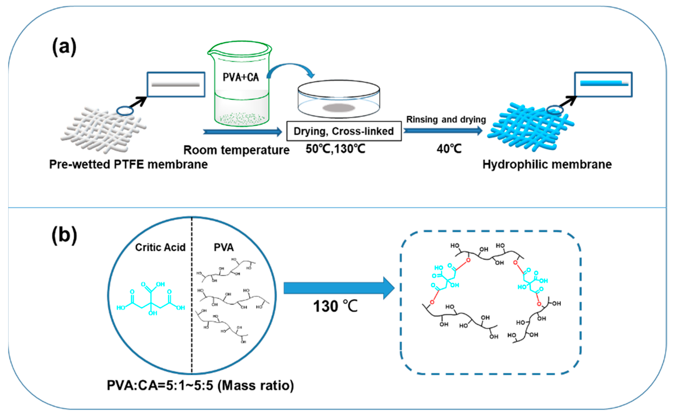
2.2. Preparation of PTFE-Modified Membranes

The PTFE microfiltration membrane was first soaked in ethanol and shaken in ultrasound for 30 min for washing to remove impurities from membrane pores. The washed PTFE microfiltration membrane is then dried.
The aqueous solution of PVA was obtained by dissolving the polymer in distilled water and stirred at 95 °C for 3 h. Then, different concentrations of CA aqueous solution were added to the PVA aqueous solution and mixed well. The PTFE microfiltration membranes were pre-wetted with different concentrations of PEGML ethanol solutions for 30 min. The pre-wetted PTFE membrane was added to the freshly prepared mixed solution for 30 min of impregnation coating. After coating, the film is taken out and placed into a vacuum-drying oven at 50 °C for 12 h and finally cured in a blast drying oven at 130 °C for 30 min to achieve crosslinking [32]. After the reaction is completed, the PTFE microfiltration membrane was thoroughly washed with deionized water until the water was close to neutral. Transfer the membrane to a vacuum drying oven at 40 °C and remove it to obtain a hydrophilized modified PTFE microporous membrane. This series of modified films is named M-PEGML_/PVA_/CA_. Moreover, we prepared PTFE microfiltration membranes modified with PVA/CA coating after pre-wetting using ethanol solution as a comparison group. This series of modified films was named M-PVA_/CA_. In addition, in order to optimize hydrophilic modification conditions, membranes pretreated with PEGML only and membranes coated with PVA solution after pre-wetting with ethanol were prepared. These two series of membranes were named M-PEGML_ and M-PVA_, respectively. The preparation conditions for all samples were recorded in Table 1.
The process of hydrophilic modified PTFE microfiltration membrane is shown in Figure 1a. The scheme of green crosslinking of PVA and CA at 130 °C is shown in Figure 1b.

2.3. Characterization of PTFE Microfiltration Membrane Structure and Surface Chemical Composition

The surface morphology of the PTFE microfiltration membrane before and after modification was observed by scanning electron microscope (JMA-5610LV, JEOL, Tokyo, Japan). Surface roughness of PTFE microfiltration membrane before and after modification was examined using laser confocal microscopy (OLS4100, Olympus, Tokyo, Japan). Analysis of the changes in groups and chemical composition of the membrane surface before and after modification was examined by using FT-IR (Nicolet iS50, Thermo Fisher Company, IA, USA) spectroscopy and XPS (ESCALAB 250XI, Thermo Fisher Company, IA, USA).

2.4. Surface Wettability and Pure Water Flux Testing of PTFE Microfiltration Membranes

The wettability of a membrane is characterized by the water contact angle of the membrane surface. The water contact angle is measured by a contact angle goniometer (DSA100, KRUSS, Hamburg, Germany) on the membrane before and after modification. A membrane is attached to a slide and mounted on the goniometer. A drop of distilled water (2 µL) is applied to the membrane surface at room temperature. The contact angle value is obtained as the average of five measurements. Each reported a reliable value as the average of five measurements. The variation of the contact angle of water drops on the membrane surface with time was also measured by using the automatic screenshot function of the contact angle instrument with a 10 s interval.
The pure water flux of the PTFE microfiltration membrane was tested using staggered flow filtration equipment (SF-MA, Hangzhou Saifei Membrane Separation Technology Co., Hangzhou, China). The M0 membrane was pre-wetted in ethanol for 0.5 h before testing, and then the pre-wetted membrane was washed in distilled water for 2 h. All the modified membranes were tested directly. Each membrane was filtered with distilled water at a pressure of 0.1 MPa for at least 60 min before testing in order to ensure a stable flux. Then, the pure water flux of the membrane was tested at a transmembrane pressure of 0.05 MPa. Each reported reliable flux result is the average of three measurements. The water flux (JW) is calculated from Equation (1):
J W = V A × Δ t
where JW is the volumetric permeate water flux (L·m−2·h−1), A is the effective permeate area of the membrane (m2), and V is the permeate volume (L) during the time interval Δt (h).

2.5. Anti-Fouling Performance Test of PTFE Microfiltration Membrane

The antifouling performance of the membranes was evaluated by staggered-flow filtration experiments at pH = 7.4 and 25 °C using an aqueous Bovine serum albumin (BSA) solution as a contaminant model. The concentration of BSA in the feed solution was 0.5 g·L−1. Prior to measurement, the modified membranes were pretreated with deionized water at 0.1 MPa for at least 60 min to ensure stable membrane flux (JW0). The membrane was then filtered with BSA solution at 0.05 MPa for 90 min. The steady-state fluxes were recorded as JWS. Afterward, the contaminated membranes were washed with de-distilled water at 0.1 MPa for 30 min in order to remove BSA molecules that were loosely deposited on the membrane’s surface. After rinsing, continue to test the pure water flux of the membrane, and the pure water flux after stabilization is recorded as the recovery flux (JWR). The three anti-fouling performance parameters of PTFE microfiltration membranes are calculated as follows.
FRR   ( % ) = J W R J W 0    
DRt   ( % ) = J W 0 J W S J W 0  
DRir   ( % ) = J W 0 J W R J W 0  
The antifouling performance of the prepared membranes was evaluated by three antifouling parameters: flux recovery rate (FRR), total flux decline rate (DRt), and reversible flux decline rate (DRir).
The BSA adsorption test evaluated the static anti-fouling ability of the PTFE microfiltration membrane. PTFE microfiltration membranes were made into 2 × 2 cm2 size and then immersed in 1 g·L−1 BSA solution for 12 h. After 12 h of impregnation, the samples were removed, and the concentration (C1) of the remaining BSA solution was analyzed by UV spectrophotometer, and the adsorption amount of BSA by PTFE membrane before and after modification was calculated using Equation (5):
Adsorption   capacity = ( C 0 C 1 ) × V A    
where C0 is the initial concentration of BSA solution (g·L−1), C1 is the concentration of BSA solution after adsorption (g·L−1), V is the volume of BSA solution (L), and A is the sample membrane area (m2).

3. Results

3.1. Surface Chemical Composition and Microscopic Morphology Analysis

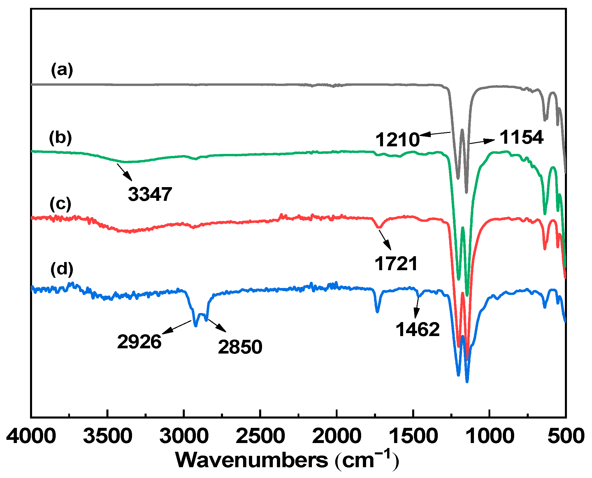
3.1.1. FTIR Analysis

Figure 2 shows the infrared spectra of the PTFE microporous membrane before and after modification. From Figure 2a, it can be observed that the M0 microporous membrane only has strong C-F bond stretching vibration peaks at 1210 cm−1 and 1154 cm−1. Figure 2b is the infrared spectrum of the M-PVA5 membrane. The broad peak near 3347 cm−1 is the -OH stretching vibration peak, which indicates the attachment of PVA to the surface of the original PTFE membrane and the introduction of the hydrophilic group -OH. In Figure 2c, the M-PVA5/CA2 membrane presents -OH stretching vibration peaks at 3347 cm−1 and the stretching vibration peak of ester carbonyl (C=O) at 1721 cm−1, which indicates the cross-linking reaction between PVA and CA [33] and the deposition of PVA/CA cross-linked coating onto the membrane surface. Meanwhile, compared with M-PVA5/CA2, M-PEGML2/PVA5/CA2 has three new characteristic peaks at 2926 cm−1, 2850 cm−1, and 1462 cm−1, which are the characteristic absorption peaks of -CH2 asymmetric and symmetric stretching vibrations and -CH2 antisymmetric deformation vibrations on the hydrophobic chain segment of PEGML, respectively. The stretching vibration peaks of -OH and ester carbonyl (C=O) were still observed. This illustrates that PEGML and PVA/CA cross-linked coatings were successfully deposited on the surface of PTFE microfiltration membranes.

3.1.2. SEM Analysis

Figure 3 shows the SEM images of the PTFE microporous membrane before and after modification. Figure 3a shows that the M0 membrane has an apparent “fiber-node” structure with uniform distribution of membrane pores and smooth fiber and node surfaces. Figure 3b shows the SEM image of M-PVA5, which shows that the “fiber-node” structure is still present, the pore size is reduced compared to the original membrane. The surface of the M-PVA5 membrane fibers and nodes became rougher due to PVA deposition on the fibers and nodes of the membrane after coating. Figure 3c shows the SEM image of the M-PVA5/CA2 modified membrane, from which it can be observed that the gel coating formed by crosslinking of PVA and CA was deposited and wrapped around the fibers and nodes of the PTFE microfiltration membrane. In Figure 3d, the M-PEGML2 membrane has the “fiber-node” structure of the microfiltration membrane. As shown in Figure 3e, the average pore size of the M-PEGML4 microfiltration membrane decreased, which was caused by more PEGML adsorbed on the fibers and nodes of the PTFE microfiltration membrane. Figure 3f shows that the hydrophilic coated layer on the fibers and nodes of the M-PEGML2/PVA5/CA2 microfiltration membrane is more uniform compared with Figure 3b,c. This is because the surfactant adsorbed on the surface of the film can reduce the surface tension of the coating solution so that the PVA/CA mixed solution spreads evenly on the surface of the film.

3.1.3. Surface Roughness Analysis
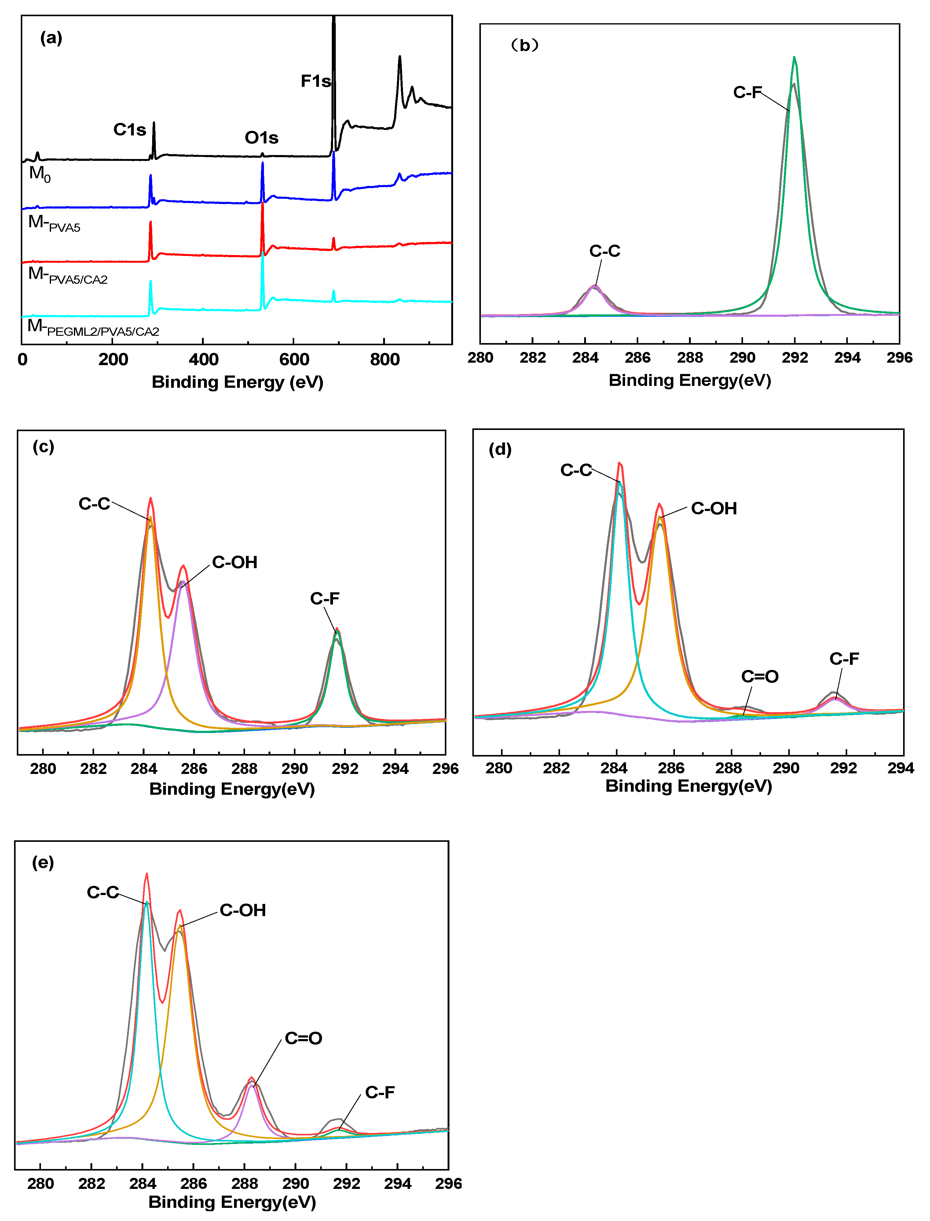
Figure 4 shows the three-dimensional scanned images of different PTFE microfiltration membranes recorded by Laser Scanning Confocal Microscopy. The root-average roughness and root-average arithmetic roughness of each microfiltration membrane are obtained in Table 2. The surface roughness of the modified M-PVA5, M-PVA5/CA2, and M-PEGML2/PVA5/CA2 was higher compared to the M0 membrane. The increased roughness of the membrane surface was a result of the hydrophilic coating deposited on the PTFE microfiltration membrane surface after modification by different methods. Moreover, the surface roughness of M-PEGML2/PVA5/CA2 was reduced compared with M-PVA5 and M-PVA5/CA2. The decreased surface roughness may be due to the pre-adsorption of PEGML on the membrane surface, which allowed the PVA/CA blend to coat the membrane surface more uniformly. This is also consistent with the results observed by SEM.

3.1.4. XPS Analysis

The XPS test can analyze the elemental composition of the membrane surface. From Figure 5a, it can be observed that M0 has distinct C1s and F1s peaks at 284.75 eV and 689.29 eV. The incomplete air extraction may cause the weak O1s peak at 545.48 eV during the test. The O1’s peak at 545.48 eV is significantly enhanced for M-PVA5, M-PVA5/CA2, and M-PEGML2/PVA5/CA2 membranes, which is caused by the deposition of different hydrophilic coatings on the surface of PTFE microfiltration membranes. Meanwhile, the chemical compositions of the different PTFE microfiltration membranes were recorded in Table 3, and the results were in agreement with those obtained by XPS spectroscopy. In order to further reveal the surface chemistry of different microfiltration membranes, we performed a split-peak fit to C1s. From Figure 5b, it can be observed that the C1s of M0 can be divided into two peaks corresponding to C-F at 291.9 eV and C-C at 284.3 eV, respectively. Figure 5c shows a new peak at 285.6 eV corresponding to C-OH in PVA, indicating that PVA is deposited onto the membrane’s surface. Figure 5d shows a new peak at 288.3 eV corresponding to the ester carbonyl group (C=O), indicating that PVA and CA crosslinked and deposited onto the membrane surface. In Figure 5e, compared with Figure 5d, it can be observed that the proportion of C=O area at 288.3 eV has increased, which indicates that PEGML was successfully deposited on the surface of the membrane. The XPS analysis results are consistent with the infrared analysis results.

3.2. Optimization of Hydrophilic Modification Conditions

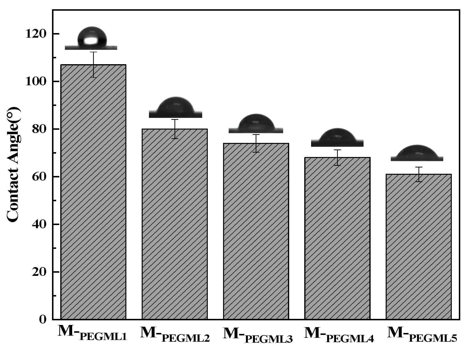
3.2.1. Effect of PEGML Concentration on the Water Contact Angle of PTFE Microfiltration Membrane

As shown in Figure 6, the changes of contact angle on the surface of the PTFE microfiltration membrane after treatment with different concentrations of PEGML solution are shown. The contact angle of the M-PEGML1 microfiltration membrane is 107°, and the surface still shows a hydrophobic state. When the PEGML concentration increased to 2 g·L−1, the contact angle of the M-PEGML2 microfiltration membrane surface decreased to 80°, and the membrane surface realized the transition from hydrophobic to hydrophilic and water droplets could wet the membrane surface. This is because PEGML can be adsorbed on the surface of the PTFE microfiltration membrane by the forces of van der Waals forces and hydrophobic interactions. Thus, the hydrophilic groups on the PEGML chain segments can enhance the hydrophilicity of the microfiltration membrane surface [31]. At the same time, the surfactant can reduce the surface tension of the liquid, thus allowing water droplets to spread out when they come in contact with the membrane surface, further wetting the membrane surface. When the PEGML concentration was further increased to 4 g·L−1, the contact angle decreased to 68°, only 12° compared to 2 g·L−1 after surfactant pretreatment. However, when the concentration of PEGML increased to 4 g·L−1, the surfactant attached to the fibers and nodes of the membrane increased significantly. Thus, the membrane pore size decreased, which may not be conducive to the subsequent deposition of PVA/CA hydrophilic coating on the surface of the membrane (Figure 4e). Therefore, in the following crosslinking treatment, the membranes were coated with 2 g·L−1 PEGML solution.

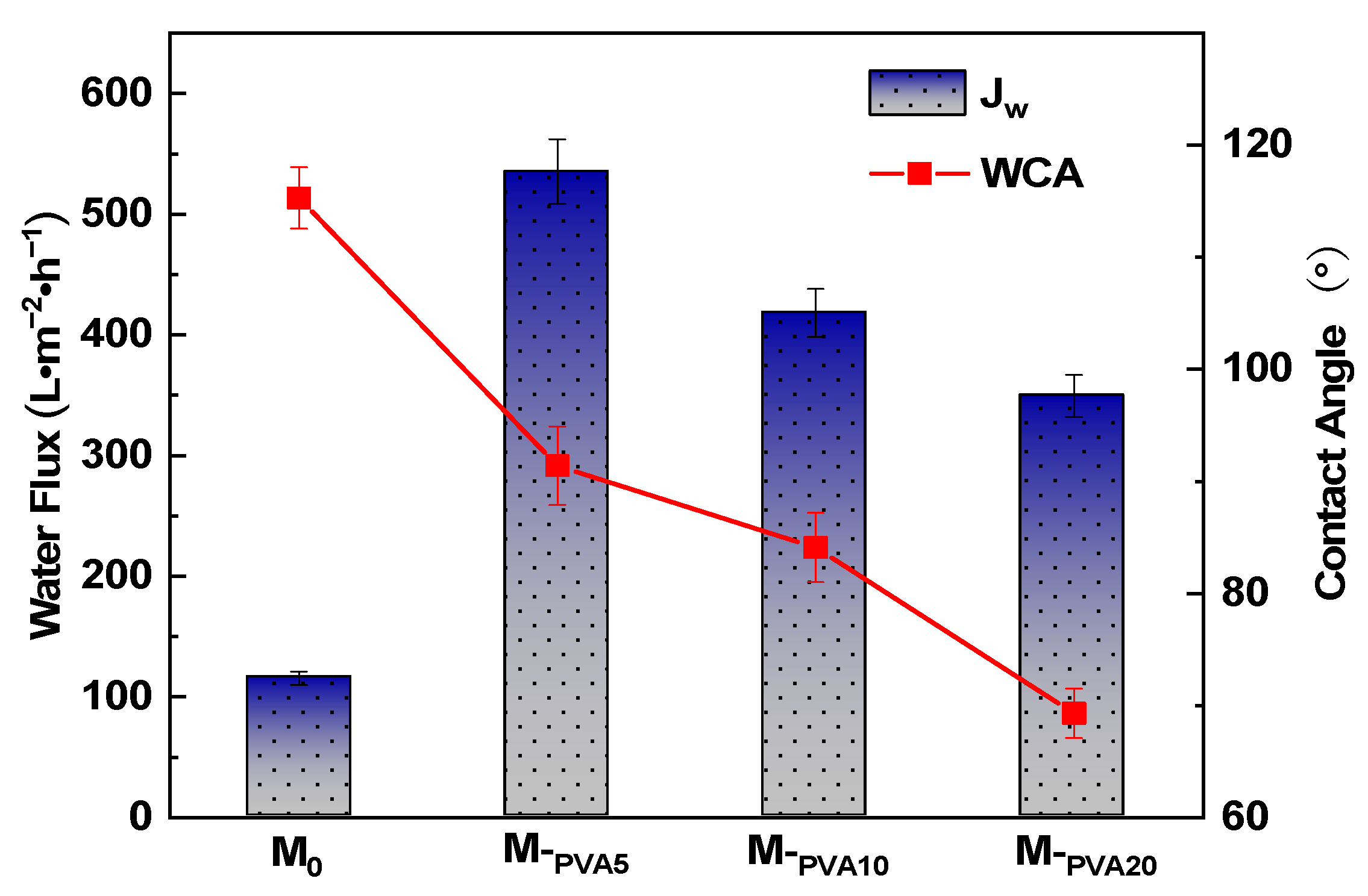
3.2.2. Effect of PVA Content on Hydrophilic Properties of PTFE

Figure 7 shows the results of water flux and water contact angle tests of PTFE microfiltration membranes modified by coating with different concentrations of PVA solution. The contact angle of the membrane surface decreases with the increase in PVA concentration. This is because the higher concentration of PVA increases the hydrophilic hydroxyl groups on the membrane surface; therefore, the hydrolysis contact angle tends to decrease. The water flux of the modified PTFE membrane shows a trend of rising and then falling, which is because the increase in PVA concentration facilitates more hydrophilic groups to attach to the fiber and node surfaces of the membrane, and the hydrophilicity of the membrane surface increases; thus, water flux rises. When the PVA concentration is higher than 5 g·L−1, the water flux begins to decrease because the further increase in PVA concentration results in some membrane pores being blocked. The average pore size of the PTFE microfiltration membrane decreases, thus resulting in a decrease in water flux. Therefore, the optimal PVA concentration in the modified conditions was 5 g·L−1.

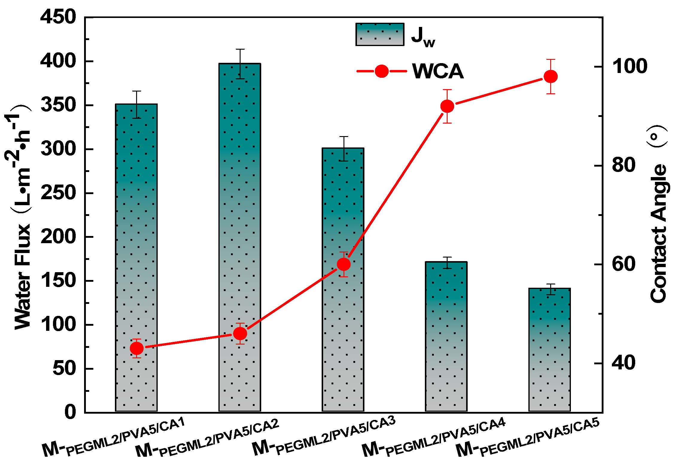
3.2.3. Effect of Crosslinker Content on the Hydrophilic Properties of PTFE

In order to enhance the stability of PVA in the aqueous phase, we used CA and PVA for chemical crosslinking. We investigated the relationship between the concentration of CA and the hydrophilic properties of the modified PTFE microfiltration membrane. The effect of the concentration of CA on the hydrophilic properties of PTFE microfiltration membranes is shown in Figure 8. Water flux increased from 350.6 L·m−2·h−1 to 396.9 L·m−2·h−1 when the concentration of CA increased from 1 to 2 g·L−1. Instead, the contact angle increased, and the contact angle increased because the increase in citric acid content consumed more hydrophilic groups hydroxyl groups. Hence, the hydrophilicity of the membrane surface decreased. The increase in water flux may be due to the swelling of the PTFE fibers and the PVA coating attached to the nodes under pure water filtration. The addition of an appropriate amount of citric acid helps enhance the crosslinking density of PVA, reducing the swelling behavior of PVA [34,35]. Therefore, the blockage of the pore size by the dissolved PVA coating is reduced, and flux is increased. At the same time, the increase in cross-linking density makes the cross-linked structure more stable, which also improves the stability of the PVA cross-linked coating in water. However, when the content of CA was further increased, the water flux showed a continuous decrease, and when the content of CA increased to 5 g·L−1, the water flux was only 140.4 L·m−2·h−1. This is because the addition of too much citric acid consumes many hydrophilic groups hydroxyl groups, making the PVA coating significantly less hydrophilic. Therefore, flux decreases, and haptic hydrolysis rises. Therefore, the optimal CA concentration was chosen to be 2 g·L−1.

3.3. PTFE Microfiltration Membrane Performance Test

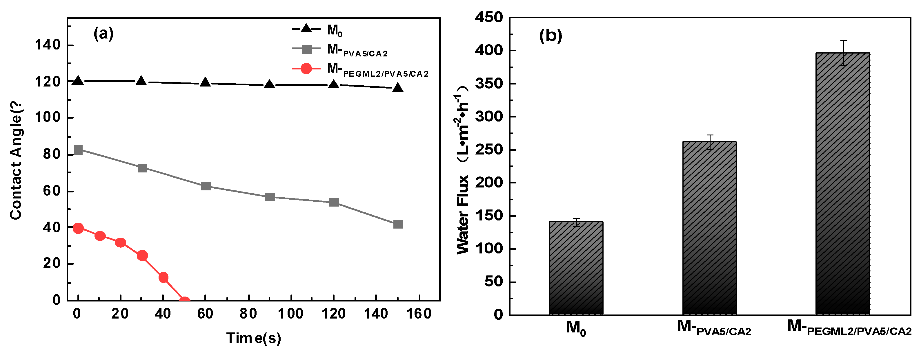
3.3.1. Hydrophilic Performance Test

From Figure 9a, we can observe that the initial contact angle of the M0 is around 120°, and there is no significant change in the contact angle within 150 s. The PTFE surface is strongly hydrophobic, and the unmodified PTFE membrane cannot be wetted by pure water. The initial water contact angle of the surface of M-PVA5/CA2 membrane was 83°, which decreased to 42° after 150 s wetting, indicating that the modified membrane has good hydrophilicity. In this case, M-PVA5/CA2 membrane formed a three-dimensional network structure on the surface of the PTFE membrane by cross-linking of PVA and CA, which enhanced the hydrophilicity of the membrane surface. The M-PEGML2/PVA5/CA2 modified membrane showed that the water droplets were wholly absorbed in 50 s and the initial contact angle reached about 40°, indicating that the modified membrane surface has excellent wettability. This is due to the deposition of PEGML on the PTFE membrane surface through hydrophobic interactions and encapsulation by PVA/CA gel coating, which further enhances the hydrophilicity of PTFE membranes. Meanwhile, the water flux test results in Figure 9b showed the same pattern, with the water flux of M-PVA5/CA2 increasing to 261.4 L·m−2·h−1, while the water flux of M-PEGML2/PVA5/CA2 further increased to 396.9 L·m−2·h−1, which is about three times the original membrane. At the same time, the modified PTFE microfiltration membrane does not require pre-wetting treatment, simplifying the use process and improving separation efficiency. We have compared our work with related work in recent years, and the results are recorded in Table 4. It can be observed from Table 4 that our modified PTFE microfiltration membrane has excellent water flux similar to other studies. At the same time, our method is simpler and cheaper than other methods. The reagents we use are environmentally friendly. Therefore, the hydrophilic modification method we use is expected to achieve industrial applications.

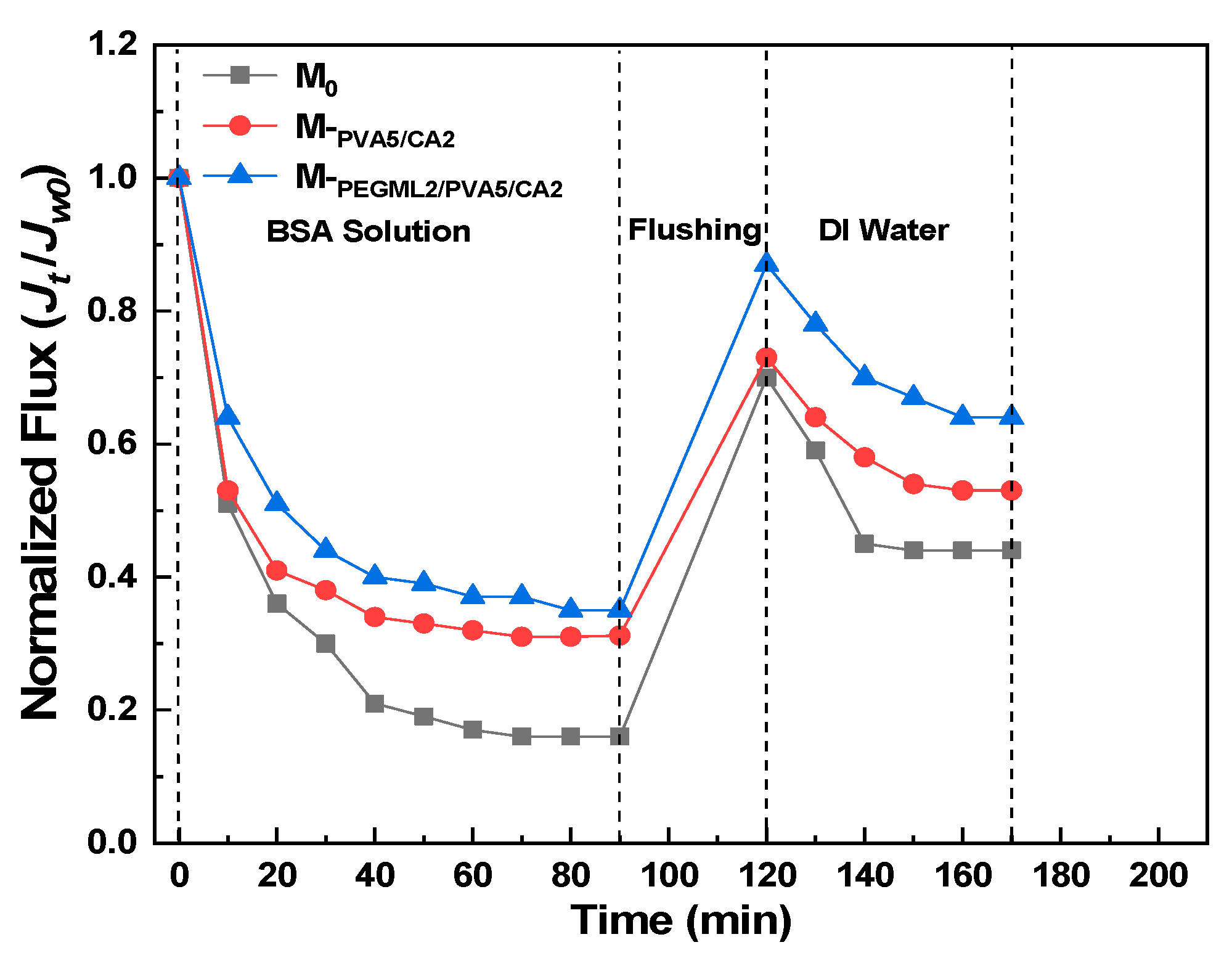
3.3.2. BSA Solution Filtration Performance Test

The relationship between the normalized flux and time of different PTFE microfiltration membranes is recorded in Figure 10, and 0 min corresponds to the stable pure water flux JW0. The lower FRR and higher DRt of the M0 can be observed in Figure 10, which indicates the poor antifouling ability of the PTFE original membranes. The hydrophobic-hydrophobic solid interaction between the PTFE membrane surface and proteins makes it difficult to recover the contaminated membrane surface by simple washing [39,40]. Compared to the original PTFE membrane, the M-PVA5/CA2 membrane showed a 9% increase in flux recovery, a 14% decrease in flux drop, and a 9% decrease in irreversible flux drop. This indicates that the BSA molecules attached to the surface of the M-PVA5/CA2 membrane are more easily repelled by water, and its antifouling ability is improved compared to the original membrane. The deposition of PVA/CA cross-linked coating on the membrane surface achieves the transformation of the PTFE microfiltration membrane from hydrophobic to hydrophilic. Thus, the hydrated layer on the membrane surface weakened the hydrophobic interaction between BSA molecules and the PTFE microfiltration membrane, resulting in improved antifouling ability [12]. The flux recovery rate, decline rate, and irreversible flux drop rate of the M-PEGML2/PVA5/CA2 membrane were further improved than compared to the M-PVA5/CA2 membrane. This is because some hydroxyl groups are consumed during the esterification reaction between PVA and CA, resulting in fewer hydrophilic groups in the PVA/CA coating. At the same time, PEGML enhances the hydration capacity of the co-deposited coating. The uniform PVA/CA coated layer makes it easier for water to wet the membrane surface. Therefore, water is more likely to wet the M-PEGML2/PVA5/CA2 membrane surface to form a hydrated layer, thus more easily preventing BSA molecules from coming into contact with the membrane surface. In conclusion, M-PVA5/CA2 and M-PEGML2/PVA5/CA2 modified membranes have superior anti-fouling ability than PTFE. Moreover, we tested the BSA adsorption of different PTFE microfiltration membranes, and the corresponding results were recorded in Table 5. Again, due to the excellent hydrophilic surface of the modified M-PVA5/CA2 and M-PEGML2/PVA5/CA2 microfiltration membranes, their BSA adsorption amounts were significantly lower compared to PTFE.

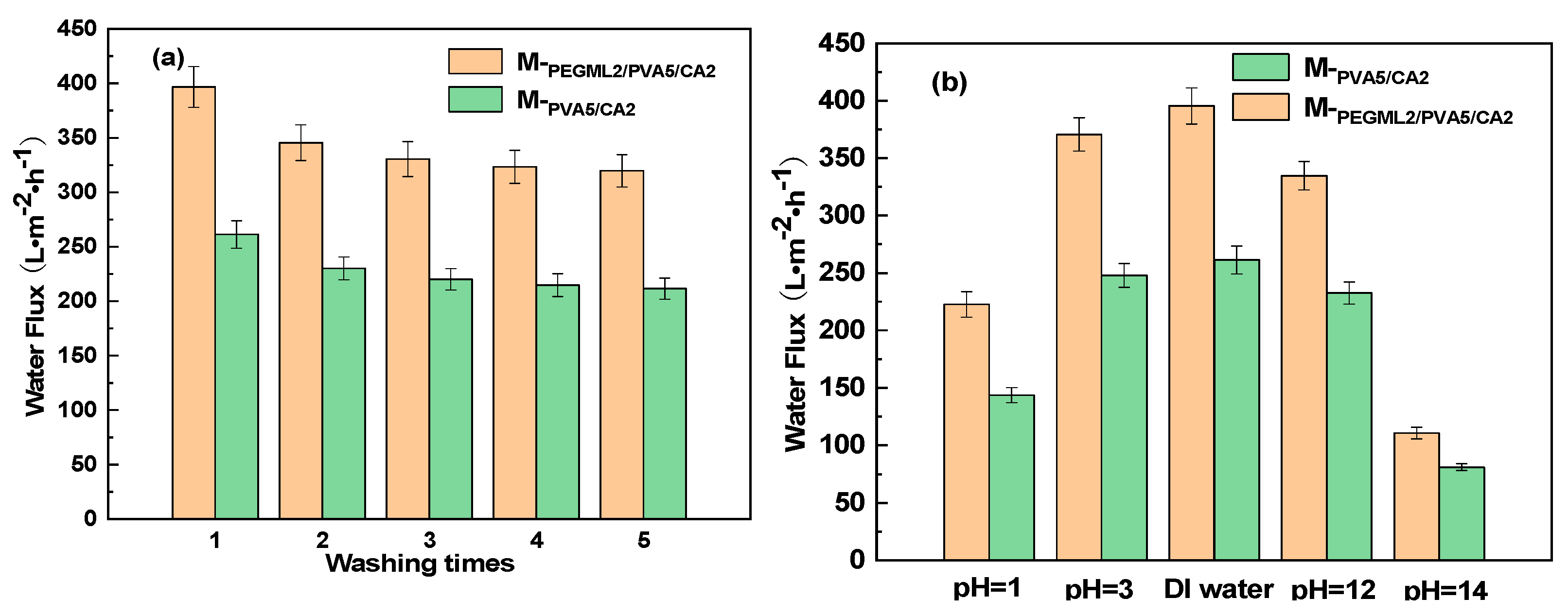
3.3.3. Hydrophilic Coating Stability Test

In Figure 11a, the water flux of the modified membrane decreases slightly with the increase in the number of washes (four hours per wash) and then stabilizes. The membrane loss of the modified membrane is slight, which indicates that the hydrophilic coating of the modified membrane has good physical stability. This is because the three-dimensional network structure formed by the cross-linking of PVA and CA is deposited and wrapped around the fibers and nodes of the PTFE membrane, which also makes PEGML more stably anchored to the membrane surface. Figure 11b shows the water flux test of PTFE microfiltration membranes after 12 h of immersion in solutions of different pH values. The flux of M-PVA5/CA2 and M-PEGML2/PVA5/CA2 membranes in pH = 3 and pH = 12 solutions does not drop much compared with the pure water environment, which indicates that these two modified membranes have good stability in these two solutions. The decrease in the flux of M-PEGML2/PVA5/CA2 and M-PVA5/CA2 modified membranes was more dramatic in solutions with pH = 1 and pH = 14. This is due to the hydrolysis of ester groups in strongly acidic and alkaline environments resulting in the exfoliation of the modified layers [11]. In conclusion, M-PVA5/CA2 and M-PEGML2/PVA5/CA2 microfiltration membranes have good stability in chemical environments ranging from pH = 3 to 12.

4. Conclusions

In this paper, a PTFE membrane was pretreated by PEGML and then crosslinked by PVA and CA at high temperatures to form a gel coating containing many hydroxyl groups wrapped around the membrane fiber surface to complete hydrophilic modification. XPS, IR, and SEM data showed that crosslinking of PVA and CA occurred and that PEGML and PVA/CA were successfully deposited onto the membrane surface. Due to the hydrophilic coating formed on the surface of the membrane, the water flux of the modified PTFE microfiltration membrane is three times that of the original membrane, and the contact angle drops to 40°. At the same time, it is easier to form a hydration layer on the surface of the hydrophilic modified PTFE membrane, which weakens the interaction between the PTFE microfiltration membrane and hydrophobic contaminants. Therefore, the antifouling ability of the modified PTFE microfiltration membrane has been improved. The modified PTFE microfiltration membrane has good flux stability in pure water and pH = 3~12 chemical environment. This is because the cross-linking of PVA and CA enables the hydrophilic layer to be firmly deposited and wrapped on the fibers and nodes of the PTFE microfiltration membrane. In conclusion, this study achieves the hydrophilic modification of PTFE microfiltration membrane by a low-cost, green, and simple method, which has good application prospects in the practical industry.

Author Contributions

Data collation, S.X. and W.M.; formal analysis, S.X., W.M. and H.Y.; funding acquisition, W.M., F.G. and C.L.; investigation, S.X. and W.M.; methodology, S.X., W.M., Z.C. and H.Y.; project management, W.M., Z.C. and C.L.; writing—original draft, S.X. and W.M.; writing—reviewing and editing, S.X. and W.M. and F.G. All authors have read and agreed to the published version of the manuscript.

Funding

This research was supported by the National Natural Science Foundation of China (21406017); the Natural Science Foundation of the Jiangsu Higher Institutions of China (18KJA430005); Changzhou Science and Technology Support Plan (Social Development) (CE20205055); the Priority Academic Program Development of Jiangsu Higher Education Institutions (PAPD); the Top-notch Academic Programs Project of Jiangsu Higher Education Institutions (TAPP); Advanced Catalysis and Green Manufacturing Collaborative Innovation Center, Changzhou University; and Postgraduate Research & Practice Innovation Program of Jiangsu Province (SJCX21_1179).

Institutional Review Board Statement

Not applicable.

Informed Consent Statement

Not applicable.

Acknowledgments

We thatnk the Changzhou Jinchun Environmental Protection Technology Co. for PTFE microfiltration membrane.

Conflicts of Interest

There are no conflict of interest to declare.

References

  1. Li, X.; Shan, H.; Cao, M.; Li, B. Mussel-inspired modification of PTFE membranes in a miscible THF-Tris buffer mixture for oil-in-water emulsions separation. J. Membr. Sci. 2018, 555, 237–249. [Google Scholar] [CrossRef]
  2. Lee, E.-J.; Kim, K.-Y.; Lee, Y.-S.; Nam, J.-W.; Lee, Y.-S.; Kim, H.-S.; Jang, A. A study on the high-flux MBR system using PTFE flat sheet membranes with chemical backwashing. Desalination 2012, 306, 35–40. [Google Scholar] [CrossRef]
  3. Li, C.; He, Z.; Wang, F.; Zhu, H.; Guo, Y.; Chen, M. Laccase-catalyzed homo-polymer of GAL and cross-linking with PEI to enhance hydrophilicity and antifouling property of PTFE flat membrane. Prog. Org. Coat. 2019, 132, 429–439. [Google Scholar] [CrossRef]
  4. Xue, S.; Li, C.; Li, J.; Zhu, H.; Guo, Y. A catechol-based biomimetic strategy combined with surface mineralization to enhance hydrophilicity and anti-fouling property of PTFE flat membrane. J. Membr. Sci. 2017, 524, 409–418. [Google Scholar] [CrossRef]
  5. Feng, S.; Zhong, Z.; Wang, Y.; Xing, W.; Drioli, E. Progress and perspectives in PTFE membrane: Preparation, modification, and applications. J. Membr. Sci. 2018, 549, 332–349. [Google Scholar] [CrossRef]
  6. Liu, H.; Liu, G.; Zhang, M.; Zhao, H.; Jiang, Y.; Gao, J. Rapid preparation of Tannic acid (TA) based zwitterionic nanofiltration membrane via a multiple layer-by-layer (mLBL) assembly strategy for enhanced antifouling performance. Sep. Purif. Technol. 2020, 253, 117519. [Google Scholar] [CrossRef]
  7. Shahkaramipour, N.; Tran, T.N.; Ramanan, S.; Lin, H.Q. Membranes with Surface-Enhanced Antifouling Properties for Water Purification. Membranes 2017, 7, 13. [Google Scholar] [CrossRef] [PubMed] [Green Version]
  8. Wang, S.; Li, J.; Suo, J.; Luo, T. Surface modification of porous poly(tetrafluoraethylene) film by a simple chemical oxidation treatment. Appl. Surf. Sci. 2010, 256, 2293–2298. [Google Scholar] [CrossRef]
  9. Liu, K.; Lei, J.; Zheng, Z.; Zhu, Z.; Liu, S. The hydrophilicity improvement of polytetrafluoroethylene by Ar plasma jet: The relationship of hydrophilicity, ambient humidity and plasma parameters. Appl. Surf. Sci. 2018, 458, 183–190. [Google Scholar] [CrossRef]
  10. Hidzir, N.M.; Lee, Q.; Hill, D.J.T.; Rasoul, F.; Grondahl, L. Grafting of Acrylic Acid-co-Itaconic Acid onto ePTFE and Characterization of Water Uptake by the Graft Copolymers. J. Appl. Polym. Sci. 2015, 132, 41482. [Google Scholar] [CrossRef]
  11. Li, C.; Wang, J.; Luo, Y.; Wang, F.; Zhu, H.; Guo, Y. One-bath two step method combined surface micro/nanostructures treatment to enhance antifouling and antibacterial property of PTFE flat membrane. J. Taiwan Inst. Chem. E 2019, 96, 639–651. [Google Scholar] [CrossRef]
  12. Liu, W.; Lin, H.; Wang, J.; Han, Q.; Liu, F. Polytetrafluoroethylene (PTFE) hollow fibers modified by hydrophilic crosslinking network (HCN) for robust resistance to fouling and harsh chemical cleaning. J. Membr. Sci. 2021, 630, 119301. [Google Scholar] [CrossRef]
  13. Song, H.M.; Yu, H.W.; Zhu, L.J.; Xue, L.X.; Wu, D.C.; Chen, H. Durable hydrophilic surface modification for PTFE hollow fiber membranes. React. Funct. Polym. 2017, 114, 110–117. [Google Scholar] [CrossRef]
  14. Wang, J.; Li, C.; Wang, F.; Yu, B.; Luo, Y.; Zeng, H.; Zhu, H. Hydrophilic modification of PTFE microfiltration flat membrane by crosslinking OCMCS-PEI to enhance anti-fouling property. Prog. Org. Coat. 2019, 135, 565–573. [Google Scholar] [CrossRef]
  15. Bell, D.J.; Ludwanowski, S.; Luken, A.; Sarikaya, B.; Walther, A.; Wessling, M. Hydrogel membranes made from crosslinked microgel multilayers with tunable density. J. Membr. Sci. 2021, 620, 118912. [Google Scholar] [CrossRef]
  16. Topuz, F.; Holtzl, T.; Szekely, G. Scavenging organic micropollutants from water with nanofibrous hypercrosslinked cyclodextrin membranes derived from green resources. Chem. Eng. J. 2021, 419, 129443. [Google Scholar] [CrossRef]
  17. Abdulhamid, M.A.; Hardian, R.; Szekely, G. Waltzing around the stereochemistry of membrane crosslinkers for precise molecular sieving in organic solvents. J. Membr. Sci. 2021, 638, 119724. [Google Scholar] [CrossRef]
  18. Chisca, S.; Bettahalli, N.M.S.; Musteata, V.E.; Vasylevskyi, S.; Hedhili, M.N.; Abou-Hamad, E.; Karunakaran, M.; Genduso, G.; Nunes, S.P. Thermal treatment of hydroxyl functionalized polytriazole and its effect on gas transport: From crosslinking to carbon molecular sieve. J. Membr. Sci. 2022, 642, 119963. [Google Scholar] [CrossRef]
  19. Gu, Y.; Zhang, B.; Fu, Z.; Li, J.; Yu, M.; Li, L.; Li, J. Poly (vinyl alcohol) modification of poly(vinylidene fluoride) microfiltration membranes for oil/water emulsion separation via an unconventional radiation method. J. Membr. Sci. 2021, 619, 118792. [Google Scholar] [CrossRef]
  20. Li, C.; Zhang, H.; Wang, F.; Zhu, H.; Guo, Y.; Chen, M. PVA and CS cross-linking combined with in situ chimeric SiO2 nanoparticle adhesion to enhance the hydrophilicity and antibacterial properties of PTFE flat membranes. RSC Adv. 2019, 9, 19205–19216. [Google Scholar] [CrossRef] [Green Version]
  21. Wang, K.; Hou, D.; Wang, J.; Wang, Z.; Tian, B.; Liang, P. Hydrophilic surface coating on hydrophobic PTFE membrane for robust anti-oil-fouling membrane distillation. Appl. Surf. Sci. 2018, 450, 57–65. [Google Scholar] [CrossRef]
  22. Wang, S.Y.; Ren, J.L.; Li, W.Y.; Sun, R.C.; Liu, S.J. Properties of polyvinyl alcohol/xylan composite films with citric acid. Carbohydr. Polym. 2014, 103, 94–99. [Google Scholar] [CrossRef]
  23. Biswal, N.R.; Paria, S. Wetting of TX-100 and lgepal CO-630 Surfactants on a PTFE Surface. Ind. Eng. Chem. Res. 2011, 50, 6138–6145. [Google Scholar] [CrossRef]
  24. Zdziennicka, A.; Janczuk, B.; Wojcik, W. The wettability of polytetrafluoroethylene by aqueous solutions of sodium dodecyl sulfate and propanol mixtures. J. Colloid Interface Sci. 2005, 281, 465–472. [Google Scholar] [CrossRef]
  25. Szymczyk, K. Wetting and Adsorption Properties of Aqueous Solutions of Ternary Mixtures of Hydrocarbon and Fluorocarbon Nonionic Surfactants in PTFE-Solution-Air Systems. Ind. Eng. Chem. Res. 2013, 52, 9106–9114. [Google Scholar] [CrossRef]
  26. Chaudhuri, R.G.; Sunayana, S.; Paria, S. Wettability of a PTFE surface by cationic-non-ionic surfactant mixtures in the presence of electrolytes. Soft Matter 2012, 8, 5429–5433. [Google Scholar] [CrossRef]
  27. Chen, X.R.; Su, Y.; Shen, F.; Wan, Y.H. Antifouling ultrafiltration membranes made from PAN-b-PEG copolymers: Effect of copolymer composition and PEG chain length. J. Membr. Sci. 2011, 384, 44–51. [Google Scholar] [CrossRef]
  28. Ding, X.L.; Kang, T.; Zhao, H.Y.; Wang, Q.; Zhang, Y.Z.; Kang, G.D. Antifouling behavior on the linear suspension PEG-based surface and two-end-linked PEG-based surface of composite nanofiltration membranes via two-step interfacial polymerization. Desalination Water Treat. 2019, 144, 9–25. [Google Scholar] [CrossRef]
  29. Khoiroh, I.; Lee, S.Y.; Pirdashti, M.; Lee, M.J. Insight into structural properties of polyethylene glycol monolaurate in water and alcohols from molecular dynamics studies. RSC Adv. 2020, 10, 21760–21771. [Google Scholar] [CrossRef]
  30. Liu, S.; Cui, S.; Qin, Z.; Zhang, X.; Zhao, Y.; Zhao, Y.; Guo, H. Modification of a Poly(tetrafluoroethylene) Porous Membrane to Superhydrophilicity with Improved Durability. Chem. Eng. Technol. 2019, 42, 1027–1036. [Google Scholar] [CrossRef]
  31. Shafiei, M.; Hajian, M. Poly(vinyl butyral)/zeolitic imidazole framework-8/poly(vinyl alcohol) thin-film nanocomposite nanofiltration membrane: Synthesis and characterization. Iran Polym. J. 2019, 28, 659–672. [Google Scholar] [CrossRef]
  32. Sabzi, M.; Afshari, M.J.; Babaahmadi, M.; Shafagh, N. pH-dependent swelling and antibiotic release from citric acid crosslinked poly(vinyl alcohol) (PVA)/nano silver hydrogels. Colloids Surf. B 2020, 188, 110757. [Google Scholar] [CrossRef] [PubMed]
  33. Ghorpade, V.S.; Dias, R.J.; Mali, K.K.; Mulla, S.I. Citric acid crosslinked carboxymethylcellulose-polyvinyl alcohol hydrogel films for extended release of water soluble basic drugs. J. Drug Deliv. Sci. Technol. 2019, 52, 421–430. [Google Scholar] [CrossRef]
  34. Wang, J.Q.; Dai, Q.L.; Si, R.Z.; Guo, S.C. Investigation of properties and performances of Polyvinyl Alcohol (PVA) fiber-reinforced rubber concrete. Constr. Build. Mater. 2018, 193, 631–642. [Google Scholar] [CrossRef]
  35. Popescu, M.C. Structure and sorption properties of CNC reinforced PVA films. Int. J. Biol. Macromol. 2017, 101, 783–790. [Google Scholar] [CrossRef] [PubMed]
  36. Huisman, I.H.; Pradanos, P.; Hernandez, A. The effect of protein-protein and protein-membrane interactions on membrane fouling in ultrafiltration. J. Membr. Sci. 2000, 179, 79–90. [Google Scholar] [CrossRef]
  37. Zhou, R.; Ren, P.F.; Yang, H.C.; Xu, Z.K. Fabrication of antifouling membrane surface by poly(sulfobetaine methacrylate)/polydopamine co-deposition. J. Membr. Sci. 2014, 466, 18–25. [Google Scholar] [CrossRef]
  38. Chi, L.N.; Qian, Y.J.; Guo, J.Q.; Wang, X.Z.; Arandiyan, H.; Jiang, Z. Novel g-C3N4/TiO2/PAA/PTFE ultrafiltration membrane enabling enhanced antifouling and exceptional visible-light photocatalytic self-cleaning. Catal. Today 2019, 335, 527–537. [Google Scholar] [CrossRef] [Green Version]
  39. Shi, H.; He, Y.; Pan, Y.; Di, H.; Zeng, G.; Zhang, L.; Zhang, C. A modified mussel-inspired method to fabricate TiO2 decorated superhydrophilic PVDF membrane for oil/water separation. J. Membr. Sci. 2016, 506, 60–70. [Google Scholar] [CrossRef]
  40. Qian, Y.; Chi, L.; Zhou, W.; Yu, Z.; Zhang, Z.; Zhang, Z.; Jiang, Z. Fabrication of TiO2-modified polytetrafluoroethylene ultrafiltration membranes via plasma-enhanced surface graft pretreatment. Appl. Surf. Sci. 2016, 360, 749–757. [Google Scholar] [CrossRef] [Green Version]
Figure 1. (a) The illustration of a hydrophilic modification of the PTFE microfiltration membrane. (b) The scheme of the green cross-linking mechanism of PVA and CA at 130 °C.
Separations 09 00002 g001
Figure 2. Infrared spectra of different PTFE microfiltration membranes: (a) M0; (b) M-PVA5; (c) M-PVA5/CA2; (d) M-PEGML2/PVA5/CA2.
Separations 09 00002 g002
Figure 3. SEM images of the surfaces of different PTFE microfiltration membranes ((a): M0; (b): M-PVA5; (c): M-PVA5/CA2; (d): M-PEGML2; (e): M-PEGML4; (f): M-PEGML2/PVA5/CA2).
Separations 09 00002 g003
Figure 4. Surface morphology images of different PTFE microfiltration membranes ((a): M0; (b): M-PVA5; (c): M-PVA5/CA2; (d): M-PEGML2/PVA5/CA2).
Separations 09 00002 g004
Figure 5. XPS spectra of different PTFE microfiltration membranes (a) and C1s XPS spectra of M0 (b), M-PVA5 (c), M-PVA5/CA2 (d), and M-PEGML2/PVA5/CA2 (e).
Separations 09 00002 g005
Figure 6. Contact angle of PTFE microfiltration membrane surface after pre-wetting with different concentrations of PEGML.
Separations 09 00002 g006
Figure 7. Water flux and water contact angle of PTFE microfiltration membranes coated with different concentrations of PVA solution.
Separations 09 00002 g007
Figure 8. Water flux and water contact angle of PTFE microfiltration membranes modified with different concentrations of CA.
Separations 09 00002 g008
Figure 9. (a) Dynamic contact angle of different PTFE microfiltration membranes; (b) water flux of different PTFE microfiltration membranes (the test pressure is 0.05 Mpa).
Separations 09 00002 g009
Figure 10. Testing of hydrophilic modified membranes for resistance to BSA adsorption.
Separations 09 00002 g010
Figure 11. (a) The relationship between the number of cleaning and water flux; (b) water flux testing in different chemical environments.
Separations 09 00002 g011
Table 1. Modification conditions of different PTFE microfiltration membranes.
Code NamePEGML(g·L−1)PVA(g·L−1)CA(g·L−1)
M0000
M-PEGML1100
M-PEGML2200
M-PEGML3300
M-PEGML4400
M-PEGML5500
M-PVA5050
M-PVA100100
M-PVA150150
M-PVA200200
M-PEGML2/PVA5/CA1251
M-PEGML2/PVA5/CA2252
M-PEGML2/PVA5/CA3253
M-PEGML2/PVA5/CA4254
M-PEGML2PVA5/CA5255
M-PVA5/CA2052
M-PEGML indicates the sample after pre-wetting with PEGML solution. M-PVA indicates the sample coated with PVA after pre-wetting with ethanol. M-PEGML/PVA/CA indicates samples pretreated with PEGML solution and then coated with PVA/CA. M-PVA/CA indicates samples pre-wetted with ethanol and then coated with PVA/CA.
Table 2. Sq (Standard deviation of asperity height) and Sa (Mean height of asperity) values of different PTFE microfiltration membranes.
SamplesSq (µm)Sa (µm)
M03.32.6
M-PVA543.2
M-PVA5/CA24.33.4
M-PEGML2/PVA5/CA23.83
Table 3. Surface element composition of different PTFE microfiltration membranes.
SamplesContent (%)
CFO
M031.5766.91.53
M-PVA558.5319.7321.74
M-PVA5/CA264.545.7529.72
M-PEGML2/PVA5/CA261.74.8933.4
Table 4. Comparison of hydrophilic modification methods of various microfiltration membranes.
MembranePWF (L·m−2·h−1)Operating Pressure (Mpa)Modification Method
PTFE (0.22 μm)3970.05PEGML/PVA Co-depositionThis work
PTFE (0.5 μm)8300.1Grafting gC3N4/TiO2/PAA after plasma treatment[36]
PVDF (0.22 μm)7850.09PDA/KH550/TiO2 Co-deposition[37]
PTFE (0.2 μm)1750.01P(VP-VTES) Crosslinking[12]
PTFE (0.5 μm)7500.1Grafting TiO2/PAA after plasma treatment[38]
Table 5. Antifouling performance parameters of different PTFE microfiltration membranes.
SamplesFRR (%)DRt (%)DRir (%)Adsorption Quantity (g/m2)
M044835620.94
M-PVA5/CA25369476.25
M-PEGML2/PVA5/CA26465364.8
Publisher’s Note: MDPI stays neutral with regard to jurisdictional claims in published maps and institutional affiliations.

