Abstract
Gas turbines must now comply with much stricter emission control regulations. In fact, to combat the greenhouse effect, regulatory authorities have drastically reduced allowable emission levels. For example, in less than 12 years, the United States’ Clean Air Act issued the New Source Performance Standards (NSPS), which tightened the NOx emission margin of natural gas combustion (from 75 ppm to 10 ppm). On the other hand, despite those efforts, the high demand for energy produced by fossil-fueled gas turbines in power plants has resulted in dramatic increases in anthropogenic CO2 and NOx emitted by gas combustors. Most systems responsible for these undesirable emissions are directly linked to power generation, with gas turbines playing a pivotal role. Yet, gas turbines are still widely used in power plants and will continue to meet the growing demand. Therefore, sequestration and separation techniques such as Carbon Capture and Storage (CCS) and Air Separation Units (ASU) are essential to reduce CO2 and NOx emissions while allowing large amounts of power to be generated from these systems. This paper provides an in-depth examination of the current state of the art in alternative working fluids utilized in the power generation industry (i.e., gas turbines, combustion). In addition, this paper highlights the recent contribution of integrating separation techniques, such as air separation, steam methane reforming, and water-gas shifting, to the power generation industry to facilitate a continuous and adequate supply of alternative working fluids.
1. Introduction
This paper examines the state of art in integrating CCS and separation units to a variety of gas turbine cycle configurations, highlighting their role in producing a continuous and sustainable supply of complex blends of working fluids, thus reducing carbon and NOx emissions and increasing the power generation cycle efficiency.
Although the progress of separation processes has been reported previously, this paper aims to correlate this progress with the potential of producing a continuous and sustainable supply of alternative working fluids to gas turbine and combustion chambers, hence delivering unique state-of-the-art evaluation. The method of evaluating the involved literature in this paper is based on providing a pros–cons evaluation of each separation process and efficiency comparison tables for each aspect in reference to its potential to produce a continuous and sustainable supply of alternative working fluids.
The literature [1,2,3,4,5] is enriched with research on the use of alternative working fluids, which have significant potential for improving gas turbine efficiency and power outputs. These increases are necessary to ensure the integration of other high-energy-consuming processes into the global carbon footprint reduction effort. Helium in the nuclear industry, ammonia–water in organic Rankine cycles, and humidified injection techniques are all examples of alternative working fluids [5,6,7,8,9,10].
Alternative working fluids are based on replacing air with an oxygen-based mixture to increase the cycle efficiency and reduce the greenhouse effect. By replacing air with oxygen-based blends, the N2 content is eliminated from the combustion process; thus, this technique eliminates NOx emissions while a cost-effective and straightforward condensation process captures carbon emissions [11,12,13,14,15,16]. The captured carbon is typically circulated back to serve as a diluting agent to avoid turbine overheating associated with oxyfuel combustion [17,18,19,20]. As far as efficiency is concerned, the cycle efficiency can be increased by increasing the overall heat capacities (i.e., specific heat at constant pressure ()) of the working fluid in the expansion stage (i.e., turbine). This is achieved by injecting components with high heat capacities (i.e., inert gases) into the working fluid, thus increasing the work output as described in Equation (1). Another approach to improving the work output is to increase the mass flow rate ()in the expansion stage by injecting steam into the working fluid as described in Equation (1), where , , , and are the turbine work, working fluid mass flow rate, isobaric mass heat capacity, turbine total inlet temperature, and turbine total outlet temperature, respectively.
As NOx emissions are eliminated from the combustion process, alternative working fluid-based gas turbines utilize diffusive combustors due to their high combustion stabilities compared to premixed combustors.
Because of their non-reactive nature combined with their thermodynamic properties, inert gases present a unique opportunity among the potential gases that can be used to increase power and efficiency. Because of its stable radioactive properties, helium is known to be the best choice in high-temperature gas-cooled nuclear reactors (HTGR) [21,22]. Efficiency losses, on the other hand, are the cost of making necessary changes to the compressor and turbine blade geometry. This results in forming an end-wall boundary layer and secondary flow, impacting the final efficiency [23]. In the literature, attempts have been made to compromise between mechanical requirements and high efficiency by introducing inert gases into the working fluid, such as neon (Ne) and helium (He). For example, by optimizing the compositions of both components, an optimal expansion ratio can be achieved.
Nonetheless, such a composition has no discernible impact on cycle efficiency. As a result, additional gases are required to improve overall efficiency, lowering maintenance and operating costs. Furthermore, to accommodate carbon sequestration at the end of the line, the gas blend should include CO2.
Oxyfuel combustion is one method for using carbon dioxide in carbon sequestration systems that is currently being developed. Oxyfuel combustion is a modern technique that substitutes high oxygen concentrations for air (i.e., with a 21 percent v. oxygen content) as the primary oxidant [24]. Compared to air–fuel combustion, oxyfuel combustion produces flue gases with approximately 75% lower mass and volume (primarily, steam, and CO2). Compared to air–fuel combustion, CO2 is captured and circulated back to the oxyfuel combustion-based gas turbine with lower heat losses, resulting in lower efficiency losses [25].
Using CO2 without injecting inert gases in oxyfuel combustion systems, on the other hand, lowers the turbine inlet temperature, necessitating higher pressure ratios to maintain the same temperature. Essentially, this entails the use of larger compressors, which impact the gas turbine’s compactness. Furthermore, existing gas turbine arrangements would necessitate significant changes, delaying the adoption of CO2 injection [25,26]. As a solution, injecting argon (Ar) into the working fluid increases the overall heat capacity by introducing another inert gas into the working fluid. Injecting Ar is a more economically sustainable option than He, Ne, or other inert gases because of its abundance in the atmosphere. By injecting argon, the turbine inlet temperature can be maintained at a constant level while maintaining high specific heat ratios for improved cycle efficiency. As a result, significant changes to existing gas turbine configurations can be avoided. Furthermore, argon’s high heat capacity boosts power outputs, offsetting the efficiency reduction penalty associated with CCS installations.
However, if only Ar-O2-CO2 blends were used as working fluids, the costs would remain significant. Therefore, advanced humidified systems could be an alternative to increase output power and efficiencies while lowering the overall costs. Complex cycles are defined as those that combine heat recovery (HR) with humidified injection techniques [27]. By recovering about 60% of heat losses, these cycles improve efficiency and reduce emissions [28]. Heat exchange and recuperation techniques, such as gas-to-gas recuperation, are examples of heat recovery methods for gas turbines with low-pressure ratios [29]. Furthermore, higher thermal efficiencies and output power are demonstrated when heat-exchanged gas turbines are compared to similar simple gas turbines. On the other hand, steam injection is a more preferable approach for higher pressure ratios [29].
As far as the evaporative cycles are concerned, they have a higher power output but lower efficiency than a similar steam injection cycle. For evaporative cycles, water can evaporate below its boiling point; thus, it does not require extensive heating (i.e., superheaters). The compressed air counter-contacts the heated water surface by placing the evaporator after the compressor. This arrangement causes molecules to collide, allowing water molecules to escape and overcome the vapor pressure [30].
Humidification can also be used for other applications, such as cooling and overcoming compressor sizing limitations, a process known as wet compression [31,32].
CARSOXY [33] is a new set of gas turbine working fluid blends created by combining all of these components, namely carbon dioxide, argon, steam, and oxygen. Previous research [33] has demonstrated that using humidification and evaporation methods can improve the performance of a gas turbine. Furthermore, when a CARSOXY mixture is used as the working fluid, heat recovery methods are used, thus increasing cycle efficiency. High techno-economic benefits can be achieved if a suitable cycle configuration is used under the specific operating condition. Furthermore, further carbon capture and storage techniques, which are considered e imperative requirements for future fossil-fueled gas turbines [34,35], have the potential to improve efficiency while maintaining a relatively low level of CO2 emissions by using a CO2–Ar–steam mixture. However, increasing the amount of CO2 in a gas turbine’s working fluid can cause carbon hydrates and blockage in cooling channels in the turbine blades [36], necessitating extra caution in determining the right amount of CO2 in the working fluid.
As discussed, evaluating the proposed novel approaches of utilizing alternative working fluids in gas turbines is based on the implementation simplicity, cycle efficiency, power outputs, economic sustainability, and acceptable combustibility criteria. Therefore, within those criteria, this paper provides an in-depth examination of the current state of the art in alternative working fluids utilized in the power generation industry (i.e., gas turbines, combustion).
In addition, applying alternative working fluids in power plants implies using separation processes (i.e., air separation, carbon capturing, steam methane reforming, water gas shifting, pressure swing adsorption, distillation, etc.). Therefore, promoting the concept of alternative working fluids to the industry is determined by the feasibility level of implementing those separation processes. Thus, this paper highlights the current contributions of integrating separation techniques, such as air separation, steam–methane reforming, and water–gas shifting to the power generation industry to facilitate a continuous and adequate supply of alternative working fluids.
As far as the integration of separation processes to gas turbines is concerned, there are two major schemes to increase the cycle efficiency or/and reduce the greenhouse effects. The first scheme uses alternative fuels, such as decarbonized fuel blends (i.e., H2 and NH3/H2), amongst many other examples in the literature [37,38]. The second scheme is to use alternative working fluids, which requires the implementation of separation processes to ensure a continuous supply of the components of the alternative working fluid. Therefore, this paper spots the integrated separation techniques to supply the components of the alternative working fluids (oxidized gas turbine cycles, H2O for humidified gas turbine cycles, CO2-diluted gas turbine cycles, and inert gas-enhanced gas turbine cycles).
In addition, air may be taken from a gas turbine facility for various reasons, such as for use as a feed to an air separation unit, bleed cooling air for the turbine, or other pressured air requirements inside the facility. The ejected air (Figure 1) includes useful heat recovered by boiling liquid fluids at discrete temperature levels or by sensible heat transfer to other fluids. Solvent regeneration, a process characterized by a gas–liquid absorption stage followed by heat transfer to the liquid to desorb a gaseous product or pollutant, is one type of use for recovered heat. The following unit activities, which may be found in hydrocarbon gasification or hydrocarbon processing facilities, are examples of processes that potentially benefit from this heat integration, including the regeneration of a cryogenic air separation unit’s liquid-based air pretreatment system. Extraction air heat recovery might benefit a liquid-based absorption phase for removing impurities from the air supply stream to an ASU. The heated air would be cooled by an absorption column against the liquid bottoms in one embodiment. The cooled air would enter the column and come into contact with the liquid absorbent, absorbing the pollutants in the air stream. The pollutants would be desorbed from the absorbent liquid, then returned to the absorbent column through the air to begin the absorbent heating process. For better efficiency removal, the absorbent system may include one or more fluids in several absorption phases or utilize specialized absorbents to remove specific pollutants in the air stream. Heating from other sources and a pressure decrease in conjunction with heating might be used to desorb contaminants from absorbents. Impurities are desorbed by heating. A gas cleaning solvent, such as that used in the syngas cleanup process, is regenerated. Absorption devices to remove acid gases from the partial oxidation process (POX) plants are widely recognized. Extraction air heat might be utilized in place of or in addition to other heat sources for solvent regeneration. A solvent-based system might be used to recover a salable by-product such as carbon dioxide from a facility’s off-gas stream. Again, heat recovered from the extracted air would be used to liberate the product stream from the solvent, either whole or partially.
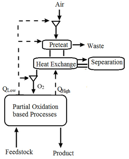
Figure 1.
ASU of Chemical PSA [39].
As illustrated in Figure 2, some of these notions can be combined. Heat can be recovered from extracted air by contacting it indirectly with a process fluid or transferring heat from the air to a working fluid such as steam or inert gas. High-level heat from the extracted air source is transferred to a nitrogen stream that returns to the gas turbine in this case. Contact with the rich bottoms of an absorption column used to pretreat air supply to the ASU further cools the extracted air. Other absorption systems in the plant’s POX or POX product workup parts might potentially perform this heat transfer phase. The high-level heat recovery phase may be omitted, and all of the extracted air heat may be utilized for absorber renewal, depending on the solvent and substance to be absorbed. Suppose the pressure was considerably different from the supplement air source. In that case, the extracted air might be mixed with supplementary compressed air entering the pretreatment process, or it may be handled independently. Carbon dioxide is collected as a by-product from the air pretreatment region in this embodiment. The carbon dioxide might be treated as a by-product for sale or utilized within the plant. Returning the carbon dioxide to the gas turbine as a diluent is one example.
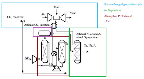
Figure 2.
Application of extracted air for heat recovery [39].
2. Carbon Capture and Storage (CCS)
The most prevalent carbon dioxide capturing techniques are discussed in this section. Pre-combustion, post-combustion, and oxyfuel combustion are the three main types. Based on multidisciplinary aspects, the literature has evaluated these techniques (technology maturity state, economic sustainability, advantages, and disadvantages).
2.1. The Main Categories of the CCS
CO2 is captured from flue gases in post-combustion CCS with no significant changes required. Post-combustion CCS can be easily integrated into existing power plants [40]; however, the electricity costs are increased by approximately 70% [41].
The Technology Centre Mongstad in Norway [42] is one of the most prominent examples of deploying post-combustion CCS commercially. According to the reference [42], the process begins by separating liquid and solid particulates from combustion flue gases in a separation unit, as shown in Figure 3. Flue gases rise from the absorber’s bottom against a counter-current stream of lean solution. This allows CO2 to be absorbed and the treated flue gases to exit the absorber at the top. Meanwhile, the CO2-rich solution travels from the absorber’s bottom to the stripper’s top. Against a counter-current water vapor stream, the CO2-rich solution flows downward. The water vapor stream absorbs the majority of the remaining CO2. Finally, CO2 is separated from water vapor using a condensation process.
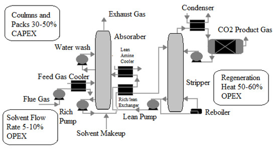
Figure 3.
A simplified diagram of a reactive solvent-based post-combustion capture process [42].
Pre-combustion CCS, unlike post-combustion CCS, is difficult to integrate into existing power plants. It necessitates extensive pretreatment, particularly for coal-fired power plants [43], which reduces the system’s compactness. On the other hand, the efficiency losses are significantly lower than those seen in post-combustion [44]. The pre-combustion CCS process begins with a coal gasification process, in which coal is converted into hydrogen, carbon monoxide, and carbon dioxide, as shown in Figure 4. This is followed by a water–gas shift reaction, which converts carbon monoxide to carbon dioxide and increases hydrogen production. Carbon dioxide can be captured at this stage using absorption, adsorption, membrane separation, hydrate-based separation, and cryogenic distillation techniques. Natural gas fuel is processed in the same way. The gasification process, on the other hand, is replaced by a reforming process. The CO2 removal efficiency of natural gas fuel pre-combustion CCS can reach up to 80% [35].
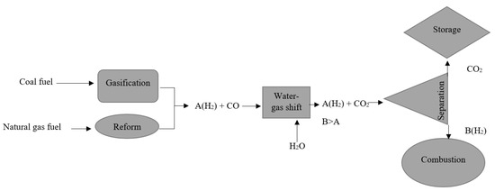
Figure 4.
CCS of pre-combustion [44].
Regarding oxyfuel combustion in CCS, the air is not directly supplied to the combustion chamber, as seen in Figure 5. It is first separated into argon, oxygen, nitrogen, and other gases in an air separation unit. The oxygen is extracted and fed into a combustion chamber. Carbon dioxide is highly concentrated in oxyfuel combustion flue gases [41], thus allowing easier carbon capturing. However, the use of the ASU for an oxyfuel lignite-fired power plant, for example, has been reported to reduce plant efficiency by up to 10% [44].
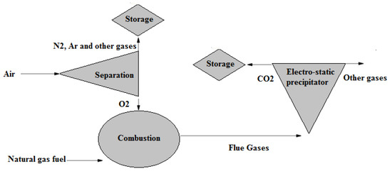
Figure 5.
CCS of oxyfuel combustion [44].
Table 1 summarizes the three CCS technologies’ maturity states, economic status, and benefits and drawbacks [44].

Table 1.
The current state of CCS technologies.
2.2. Methods for Separating Carbon Dioxide
CO2 is separated by absorption using liquid sorbents, and stripping techniques can be used to extract the latter. Monoethanolamine (MEA) ensures a CO2 absorption efficiency of 90% [45]. Adsorption [45] is the technique used when the sorbent is in the solid phase (such as hydrotalcite, molecular sieves, and so on). Another well-known technique is membrane separation, which allows CO2 to pass through a porous composite polymer selectively. Because different gases have different molecule sizes, pores are carefully sized to match the size of the CO2 molecule [46]. Table 2 [46] compares and contrasts the benefits and drawbacks of the most common CO2 separation techniques.
Table 2.
CO2 pros and cons.
2.3. CO2 Storage
Structural and stratigraphic, residual, solubility, and mineral trapping are the four primary trapping mechanisms for CO2 storage [47]. Once CO2 is injected underground, it rises to the top of geological structures, owing to the buoyancy effect. Still, it remains below the impermeable caprock with structural and stratigraphic trapping, which is the most prominent trapping process. The injected CO2 displaces formation fluid as it passes through the formation rock in residual trapping. Due to the capillary force, the displaced fluid disconnects and traps the remaining CO2 inside the pores of rocks [48]. The saturation of trapped CO2 in the residual trapping mechanism is at least 10% and can reach more than 30% of the pore volume in some reservoir rocks [49]. CO2 dissolves in formation fluids and becomes immobile, resulting in a reduction in the amount of free CO2 [36]. The density of the formation fluid will be slightly increased by about 1% due to the dissolved CO2. Such a small density differential [36] is adequate to induce convection flow, which is also beneficial to CO2 trapping. CO2 solubility in groundwater varies between 2% and 6%, decreasing with increasing temperature and salinity [50]. CO2 is held in the mineral trapping mechanism by geochemical processes in the reservoir, which generally precipitate as carbonate, effectively trapping CO2 in immobile secondary phases [50].
In a period ranging from 1 to 10,000 years, various trapping processes play distinct roles in CO2 storage. Structural trapping is vital in the early stages of CO2 storage, but its impact fades over time. Within decades, residual trapping and solubility trapping significantly influence and lock up a large quantity of CO2 for thousands of years. Mineral trapping begins to have a substantial influence around a hundred years and plays a critical function in a geological timeframe.
For various reasons, storing CO2 in hydrocarbon reservoirs is one of the most preferred CO2 storage options. For example, oil and gas reservoirs contain a large quantity of existing equipment on the surface and underground that may be utilized for CO2 storage with only minimal modifications. Furthermore, the caprock’s seal quality and integrity are assured, having been thoroughly defined during the exploration and production process. Moreover, because of the long-term extraction of oil and gas, the magnitude of pressure perturbations and associated stress shifts in depleted oil and gas reservoirs is significantly smaller than in aquifers. Depleted gas reservoirs are more suitable for CCS than depleted oil reservoirs because of gas’s higher ultimate recovery and compressibility and a bigger storage capacity per pore volume. When comparing the types of reservoirs utilized in this type of storage, condensate gas reservoirs outperform wet and dry gas reservoirs due to the small amount of residual gas, the phase behavior of the combination of condensate gas, and CO2, and its high injectivity. Additionally, the amount of CO2 sequestered per pore volume in depleted condensate reservoirs is relatively high: around 13 times that of a comparable aquifer. Yet, the phase transition may occur in depleted condensate reservoirs but not in dry and wet gas reservoirs; therefore, caution is advised.
3. Air Separation Unit (ASU)
The concept of oxyfuel combustion is based on utilizing pure oxygen as the primary working fluid while eliminating nitrogen to avoid NOx emissions. As previously mentioned, pure oxygen is typically accompanied by inert gases, such as argon, for its high heat capacity, to increase the cycle efficiency. Therefore, to separate oxygen and argon from the air while excluding nitrogen from the combustion process (i.e., to avoid NOx emission), air separation techniques are integrated into oxyfuel combustion-based power plants [51].
3.1. Types of Cryogenic Distillation
Cryogenic distillation can be performed using a single distillation column or multiple distillation columns. The multi-column process [52] is, however, the traditional method. A low-pressure column, a high-pressure column, and a side rectifier or strippers are the main components of this process. The cost of multi-column distillation remains a challenge. However, several cost-effective improvements have been proposed in the literature [52] and are detailed in the following sections.
3.1.1. Thermally Linked Distillation Column, with a Side Rectifier
According to the reference [53], A ternary mixture made up of A, B, and C components (i.e., N2, Ar, and O2 in air, respectively) are separated, as shown in Figure 6. The most volatile component is A (i.e., N2 in the air), followed by B and C (i.e., Ar and O2 in air, respectively), the intermediate and least volatile components, respectively. The mixture is supplied to the main distillation column, which extracts component A (i.e., N2 in air) from the top. From the bottom, component C (i.e., O2 in air) is extracted. The ABC (i.e., air) mixture’s main feed is located approximately in the middle of the distillation column. The side feed is connected to the bottom of the rectifier and located just beneath the main feed. B and C (i.e., Ar and O2 in air, respectively) are the components of the side feed mixture. B (i.e., Ar in the air) is produced from the top of the side rectifier, while the C (i.e., O2 in the air) component accumulates at the bottom of the side rectifier. At the same location as the side feed, component C (i.e., O2 in the air) from the side rectifier is recycled back into the main column. When the relative volatility of the two components (B and C (i.e., Ar and O2 in the air)) in the side feed is low, this method is used.
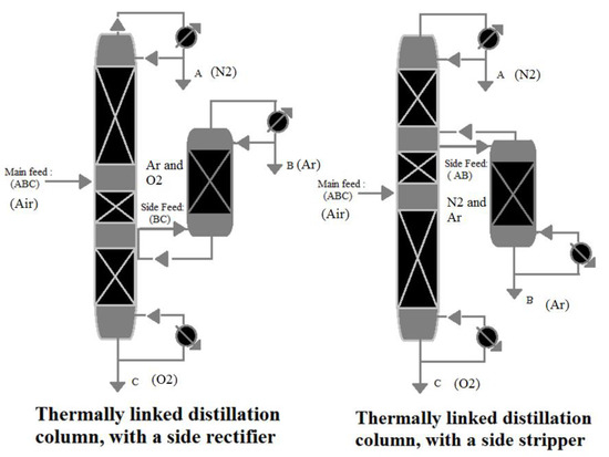
Figure 6.
Thermally linked distillation column, reproduced from the reference [53].
3.1.2. Thermally Linked Distillation Column, with a Side Stripper
A side stripper is a better choice if the low relative volatility is between (A and B) rather than (C and B). The side feed is linked to the top of the stripper and is located above the main feed, as shown in Figure 6. The side feed mixture comprises A and B, with B produced at the stripper’s bottom, whereas A is returned to the main column.
3.1.3. Side Rectifier vs. Side Stripper
The concept of using ternary mixture distillation on air is depicted in Table 3. Because argon and oxygen (B and C) have lower relative volatility than argon and nitrogen (B and A) [54], a side rectifier is a more proper choice for air separation.
Table 3.
Air components relative volatility [54].
3.2. Low-Pressure (LP) Distillation Column vs. Elevated-Pressure (EP) Distillation Column
Low-pressure distillation columns are used if the by-products of nitrogen production (oxygen and argon) are not stored and discharged near atmospheric pressure. The storage of oxygen and argon, on the other hand, necessitates an additional increase in pressure. As a result, evaluated-pressure distillation columns are utilized. To put it another way, if the by-products of producing nitrogen are compressed and used as main products, an elevated-pressure distillation column is required [52]. The elevated-pressure distillation column provides better matching between the ASU and the gas turbine unit; for example, the working fluid of CARSOXY gas turbines is required to operate at relatively high pressure; thus, elevated-pressure (EP) distillation columns are required [50].
3.3. Single Distillation Column vs. Double Distillation Columns
In comparison to conventional double distillation columns, self-heat recuperation of a single distillation column saves 36% of energy consumption, according to the reference [46]. Liquefaction and air compression are the significant losses in a double-column air separation process. Double distillation columns, on the other hand, are still the most popular. Table 4 provides a critical assessment of the air separation methods.
Table 4.
Pros and cons of the air separation methods (distillation).
3.3.1. Conventional Argon Production
Air is fed to the ASU through a heat exchanger at about 5.5–6.5 bar, as shown in Figure 7, to be cooled by its products. The first stage is a high-pressure (HP) stage, and the second stage is a low-pressure (LP) stage in a two-stage distillation column that separates oxygen and nitrogen. At the HP stage, the air feed is separated into N2 and oxygen-enriched liquid (liquid oxygen (LOX)) at the HP stage. The latter is passed through the LP stage, where it is separated into N2 and O2. There is a temperature difference between the two stages due to the pressure difference. This allows heat exchange between the two stages (between LP and HP), in which the N2 vapor-boiling stream at the top of the HP stage is then condensed by the colder liquid O2 at the bottom of the LP stage. From the top of the HP column, N2 is produced. The highest argon concentration is found in the lower section of the LP column due to its intermediate boiling temperature. A vapor stream is drawn to feed the rectifier from this location. The vapor argon-boiling stream at the top of the rectifier is condensed by the colder LOX liquid, similar to the main distillation column. LOX that has been vaporized is returned to the LP column.
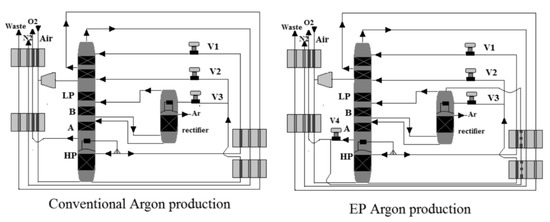
Figure 7.
Thermally linked distillation column, reproduced from the reference [53].
3.3.2. EP Argon Production
As shown in Figure 7, oxygen in the liquid phase is drawn from the bottom of the LP to provide total condensing duty, while argon is drawn from the top of the rectifier column to improve argon recovery due to the elevated-pressure process’s tight volatility. The vaporized oxygen serves a second purpose after completing the total condensing duty. As the EP process reaches higher temperatures, it is used as a coolant agent in the system. Because of the heat pump effect between the argon rectifier and the oxygen at the bottom of the LP column, the pressure at the top of the rectifier remains lower than the pressure at the bottom of the LP column, requiring no compressor.
3.4. Membrane Air Separation
One of the most important ways to generate oxygen from air separation is using new ceramic membranes with mixed electronic ionic conducting (MIEC) properties. Figure 8 depicts a schematic of an oxyfuel combustion power plant using an MIEC membrane. As shown in Figure 8, an air compressor may pressurize air to a pressure of 10 bar. Both the membrane and the air must be subjected to temperatures exceeding 800 °C, as well as an oxygen partial pressure ratio across the membrane, to accomplish air separation. A combination of air compression, flue gas recycling, and boiler heat exchange can provide the heat necessary to reach this high temperature. Surprisingly, the front end of an oxyfuel combustion plant can accommodate the ceramic membrane module. Because of the continuous oxygen partial pressure drop across the membrane, which is one of the technological aspects of such integration, using recovered CO2 from the combustion process might result in a strong oxygen driving force. Oxygen penetrates selectively through a membrane into the recycled CO2 stream from the compressed air side, enriching it to around 20% (v/v) [55]. After that, the oxygen-enriched CO2 stream may be burned directly in the boiler, resulting in superheated steam that can be used to power steam turbines and generate electricity.
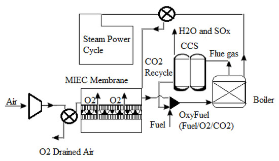
Figure 8.
Diagram of an oxyfuel power plant using an MIEC membrane module [55].
As shown in Figure 9, there are two distinct approaches for integrating an MIEC membrane into the oxyfuel combustion process. The notion of enabling recirculated flue gas to pass over the membrane surface is used in Figure 9a, allowing oxygen to be absorbed directly. This so-called four-end approach [56,57,58] is intended for Integrated Gasification Combined Cycle (IGCC) processes; however, CO2-resistant membrane materials such as Ba0.5Sr0.5CO0.8Fe0.2O3I (BSCF) do not exist. As a result, BSCF membranes can only be used when the membrane material is not in direct contact with the flue gas. On the other hand, the three-end idea [59,60] depicted in Figure 9b appears to be an appealing alternative, as it avoids direct contact between the membrane and the flue gas. A vacuum pump is used to remove oxygen from the membrane module in this scenario. Although the first concept achieves a higher thermal efficiency in the oxyfuel combustion process, the three-end concept is more likely to be feasible because no membrane materials exist that can withstand direct contact with the flue gas; therefore, membrane material development is critical [61,62,63]. Kneer et al. [56] effectively provided the requirements of coal combustion in a CO2/O2 environment, including associated burner design, as well as the cleaning of hot flue gas from oxycoal combustion, in their article on membrane-based air separation modules and their design for oxycoal circumstances.
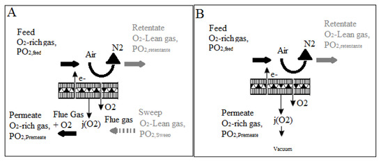
Figure 9.
(A) four-end approach and (B) the three-end concept for oxygen separation in oxyfuel processes [62].
It is worth noting that there are several problems with using this innovative approach for obtaining oxygen from air separation. To offer high oxygen penetration flux, the membrane separation system must first be run at temperatures exceeding 900 °C. As a result, because the heated air includes around 80% (v/v) nitrogen as waste gas, there will be significant energy penalties in this operation. Although process efficiency losses can never be entirely recovered, energy losses can be minimized by adequately implementing heat recovery. Second, while the strong oxygen driving force of high CO2 partial pressure is appealing to membranes, the aggressive circumstances would lead these membrane materials to break down, limiting their efficacy in generating oxygen for the oxyfuel combustion process. The high need for oxygen for the oxyfuel combustion process is likely to lead to the deployment of oxygen membrane separation technology in the near future; nevertheless, continuing research and development is critical to overcome the significant challenges. In summary, the oxyfuel power plant is an appealing choice due to a considerable cost decrease in oxygen generation when carbon capture becomes a requirement in the future. As a result, ceramic membranes are thought to be an effective high-temperature air separation technology that might result in a significant cost decrease in the generation of oxygen for this application.
It should be mentioned that an IGCC coal-fired power station combines two technologies, coal gasification and combined cycle, to produce energy in the most efficient manner possible [63,64]. Traditionally, the oxygen supply for coal gasification has been obtained by cryogenic distillation; however, it has been observed that this technique has many inefficiencies [65]. The use of solid oxygen carriers as an alternate way of producing oxygen has also been investigated, including CaSO4 [66,67] and other oxygen carriers such as manganese [68], nickel [69], and iron [70,71] oxides. However, there are drawbacks to using this technique, including sluggish response speeds, solid handling, and a huge solid oxygen carrier inventory [70,71]. Because these membrane modules have no moving parts and are thus simple to run and maintain, introducing a revolutionary technology based on ceramic membranes for oxygen generation from air separation is thought to enhance the efficiency of IGCC power plants.
Table 5 provides a critical assessment of the membrane air separation methods.
Table 5.
Pros and cons of the membrane air separation methods.
4. Steam Methane Reforming (SMR)
SMR is an essential step in the carbon capture and storage (CCS) process, as discussed in Section 5.1. Furthermore, it is one of the fully developed technologies for producing hydrogen. The results and conditions in real life are identical to those in theory [72]. When a light hydrocarbon fuel (such as methane) reacts with steam, it produces hydrogen as the primary product and carbon monoxide and carbon dioxide as by-products. Since WGS processes accompany SMR in most applications, some literature includes WGS as a step in SMR [72]. Two endothermic reactions occur during the reforming process. One mole of methane to one mole of steam requires 206 kJ in the first reaction. This yields 3 moles of hydrogen and 1 mole of carbon monoxide as a by-product. WGS makes use of the hydrogen produced by this reaction by converting carbon monoxide to hydrogen and carbon dioxide as a by-product [73]. The second reaction, which produces hydrogen and carbon dioxide directly instead of one mole of methane reacting with two moles of steam, does not require WGS because it directly produces hydrogen and carbon dioxide. It uses 165 kJ and emits 4 moles of hydrogen and 1 mole of CO2. Finally, the CCS process is used to capture all of the carbon dioxide produced during the entire process. Figure 10 depicts the whole procedure.
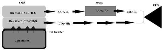
Figure 10.
SMR process, reproduced from the reference [74].
The SMR process is characterized by harsh reaction conditions [74]. Because reactions 1 and 2 are both endothermic, the temperature rises to around 1000 K. It has even been described as a “brutal” process [73]. Both reactions take place in a catalytic environment. Table 6 [74] explains that the catalyst must be carefully selected to withstand these extreme conditions.
Table 6.
SMR catalyst [75].
Because of well-developed methane infrastructures and methane’s favorable hydrogen-to-carbon ratio, methane steam reforming is commonly regarded as a readily available technique for producing hydrogen on a large scale [76]. Fuel cell technology needs small, low-cost reformers [77,78]. Compact reformers should be operated at low temperatures (<1000 K) and pressures (3 bar). As a result, the present large-scale reformer technology, which operates at high temperatures (>1100 K) and pressures, is incompatible with smaller-scale reformers for fuel cell applications [79]. Methane steam reforming is a substantially endothermic process. The exothermic water–gas shift process is also included, which is more favorable at low temperatures (500–850 K). The benefit of executing the steam reforming process at low operating temperatures is that the applied temperature promotes the water–gas shift reaction by suppressing the CO quantity [80]. Creating an active catalyst capable of achieving conversion up to equilibrium levels is the primary disadvantage of methane steam reforming processes at low temperatures [81,82,83]. Several groups investigated catalyst performance in methane steam reforming at temperatures above 1000 K [84,85,86].
5. Water–Gas Shifting (WGS)
Water–gas shifting is a chemical reaction that converts carbon monoxide and water into carbon dioxide and hydrogen. It is one of the most essential processes in carbon capture and storage. About 40 kJ is generated when one mole of carbon monoxide is reacted in the WGS reaction. Two types of catalysts (iron-based and copper-based) are commonly used to speed up the reaction [87].
5.1. WGS Applications
Water–gas shifting is an area of interest whenever carbon monoxide is an unwanted by-product gas. It is, in fact, a very reliable method of purifying hydrogen produced by steam hydrocarbon reforming processes. This process is typically integrated with the SMR process, Reactions (2) and (3) [26], as discussed in Section 7.
Steam reforming of methane: H2O + CH4 ↔ CO + 3H2
Water–gas shift reaction H2O + CO ↔ CO2 + H2
Ammonia production is another industrial application that relies heavily on water–gas shifting to prevent carbon monoxide from reacting with the catalyst [88]. Ammonia production is likely to be a part of the gas turbine cycle, primarily if evaporation injection techniques are used [88].
5.2. WGS Catalyst
The two most important factors to consider when selecting catalysts for the WGS process are sulfur tolerance and operation temperature. Iron-based catalysts have a low sulfur tolerance and operate at a high temperature (approximately 680 K). Carbon-based catalysts are used at lower operating temperatures (around 480 K). On the other hand, it has a low tolerance level for sulfur [89]. The main properties of the iron-based and copper-based catalysts are shown in Table 7 [89].
Table 7.
WGS catalysts.
5.3. WGS Reactors
The conventional WGS process consists of two reactors. It uses an iron-based catalyst in a high-temperature reactor (HTWGS). The high-temperature reactor’s products are cooled before being purified from CO in a low-temperature reactor (LTWGS) with a copper-based catalyst. This option is ideal if the reactor’s inlet boundary condition is high, and the desired product (H2 and CO2) must be produced at a low temperature with very low CO residuals.
Figure 11 [51] shows a WGS reactor with a shell-tube design. A hydrogen-selective membrane tube is inserted into a shell. The catalytic WGS reaction is carried out around the tube (inside the shell). The membrane performs the separation function by allowing only H2 to pass through (inside the tube), while the remaining WGS products are extracted as a CO2-rich mixture outside the tube.
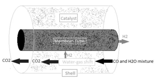
Figure 11.
Shell-tube WGS reactor, reproduced from the reference [80].
6. Helium as a Working Fluid
Many nations, including Russia, Europe, South Africa, Japan, and the United States, are studying direct and indirect Closed Brayton Cycle (CBC)-based high-temperature gas-cooled reactors (HTGRs) that employ helium as a coolant for energy conversion. Because of its outstanding transport characteristics, helium is regarded as the best coolant. According to the data, helium has been utilized as the working fluid and coolant in 9 of the 15 closed Brayton cycle nuclear reactor systems built across the world since the 1960s [90]. However, because helium is less compressible than air, more stages are necessary to compress it to the desired pressure ratio in an axial compressor. As a result, every helium compressor ever built has a large number of stages. The Oberhausen II type 50 MW reactor’s high- and low-pressure compressors each contain 25 stages [90]. As a result, the helium turbo equipment is rather substantial in terms of both size and weight. This situation is unfavorable because it raises various losses, such as the formation of a multi-stage narrow fluid flow channel. As a result, there is an increase in aerodynamic loss due to leakage, separation, and boundary layer loss. As a result, the stator and rotor stages are mismatched. Aside from that, compressors with narrow rotors cause dynamic difficulties [91,92]. As a result, there is a pressing need to address this problem since smaller shafts with two spools turbo machinery enhance plant efficiency over longer shafts because they are easier to maintain, perform better dynamically, and have high rigidity [93]. An extensive study is being carried out to identify the most viable working fluid for utilization in HTGR systems with increased thermal efficiency, electrical productivity, decreased size, and lowest rotational loss to solve the problem mentioned above.
On the other hand, researchers devised a novel design approach for a heavily loaded helium compressor to minimize the number of stages in the helium compressor. This design approach is based on changing the form of the airfoil or blade when torsional velocity, axial velocity, and negative pre-spin increase. As a result, stage loading increases [15]. Numerical simulations of a heavily loaded helium compressor were carried out using the commercial program Ansys, and it was discovered that this design method can minimize the number of stages. Still, no experiment has been carried out using it. Noble gases and their mixes are not yet used as a working fluid in CBCs. Certain factors influence the choice of working fluid for the HTGR system’s power conversion unit. Noble gases and their mixes are the subjects of many studies for use as a working fluid in CBC HTGR plants and axial flow turbomachinery [94,95]. Many investigations have been carried out to evaluate the heat transmission process of the HeXe mixture in triangular channels [95], cylindrical channels [96], beginning pipe sections [97], and heated channels with varied cross-sectional forms [98]. The HeXe gas mixture’s thermodynamic characteristics and transport constants were also calculated [98]. HeXe was also used in the Prometheus project. It was based on a Brayton energy conversion loop with a single reactor heat source [99].
7. Conclusions
Local and regional regulations have been established to limit NOx and CO2 emissions as part of this global commitment. Most systems responsible for these undesirable emissions are directly linked to power generation, with gas turbines playing a pivotal role. As a result, stationary gas turbines have been widely used in power plants and will continue to be used to meet the growing electricity demand. As a result, novel concepts are needed to reduce emissions while allowing large amounts of power to be generated from these systems. One promising technology for reducing harmful emissions while recirculating CO2 in the combustion process is alternative working fluids. The idea behind using alternative combustion working fluids is to replace air with oxygen, carbon dioxide, steam, or inert gases, either individually or collectively.
Using carbon dioxide as a working fluid in an oxyfuel gas turbine keeps the temperature of the turbine within acceptable limits and reduces heat losses, all while removing NOx emissions. Chemical kinetics, flammability regions, and flame compactness, on the other hand, are negatively affected. Increased oxygen levels could lessen the severity of those negative consequences. However, air separation units will be required to provide more oxygen, resulting in additional costs. As a result, it can be concluded that using CO2- O2 as a working fluid (without any additional components to improve overall thermodynamic properties) poses significant technical challenges and is unlikely to be implemented on a large scale.
When compared to conventional air-driven simple cycle gas turbines, the main benefit of injecting steam into gas turbines is an increase in cycle efficiency and specific power outputs. However, based on the research on O2-H2O-CH4, it can be concluded that O2-H2O-CH4 power plants do not always achieve higher efficiencies and power outputs than air-driven cycles (i.e., aero-derivative and industrial combined cycles achieve higher efficiencies and power outputs than steam-injected or (O2-H2O-CH4) gas turbines). As a result, humidification techniques should be used with caution to achieve higher efficiency than air-driven cycles. O2-H2O-CH4 combustion/power plants showed more advanced properties, as shown in Table 7. However, those properties (laminar flame speed, CO emissions, and exergy efficiency) are only compared to the literature’s O2-CO2-CH4 combustion/power plants. They must be benchmarked against air-CH4 combustion/power plants in future studies.
Due to their higher specific heat ratios and potential for increasing cycle efficiency compared to air, argon, xenon, and helium have been studied as working fluids in the context of using inert gases in combustion and power generation. In comparison to air-driven cycles, using helium as a working fluid in closed cycles has the potential to improve cycle efficiency. However, these techniques have not yet matured to the point where they can be used on a large industrial scale (i.e., helium leakage is not easily controlled due to its low molecular weight).
Due to the high specific heat ratio of xenon (1.677) and argon (1.667) compared to nitrogen (1.401), using oxygen–argon and oxygen–xenon mixtures is expected to increase cycle efficiency while eliminating NOx. However, because argon has a higher abundance and mixing rate than xenon, it is more likely to be used in combustion in the future.
The advantages of using carbon dioxide to keep turbine temperatures within acceptable ranges, argon to increase specific heat ratio, steam to increase mass flow rate, and oxygen to eliminate NOx emissions are incorporated into the CARSOXY working fluid concept.
As discussed, evaluating the proposed novel approaches of utilizing alternative working fluids in gas turbines is based on the implementation simplicity, cycle efficiency, power outputs, economic sustainability, and acceptable combustibility criteria. Therefore, within those criteria, this paper provides an in-depth examination of the current state of the art in alternative working fluids utilized in the power generation industry (i.e., gas turbines, combustion).
In addition, applying alternative working fluids in power plants implies using separation processes (i.e., air separation, carbon capturing, steam methane reforming, water gas shifting, pressure swing adsorption, distillation, etc.). Therefore, promoting the concept of alternative working fluids to the industry is determined by the feasibility level of implementing those separation processes. Consequently, this paper has highlighted the current contributions of integrating separation techniques, such as air separation, steam methane reforming, and water–gas shifting to the power generation industry to facilitate a continuous and adequate supply of alternative working fluids.
Finally, the decision of choosing the composition of the optimal working fluids can be made through numerical analyses that correlate the individual effect of each component to the overall composition with respect to the gas turbine cycle efficiency. As an example of this practice, the reference [48] has related the components of the alternative working fluid with respect to the cycle efficiency through a three-dimensional efficiency surface that correlates three intervals of variable molar fractions of carbon dioxide, argon, and steam. The highest cycle efficiency is visualized as the highest peak on the efficiency surface within the tested intervals of molar fractions. As a result, the optimal blend was determined by selecting the corresponding molar fractions (to the highest peak).
As highlighted previously, the idea behind using alternative combustion working fluids is to replace air with oxygen, carbon dioxide, steam, or inert gases. Therefore, ASU is utilized to produce the required oxygen and argon content. Steam and carbon dioxide are supplied to the alternative working fluid mixture by integrating humidification and CCS techniques. However, to produce the required molar fractions to achieve the optimal working fluid blends, the operating conditions of the integrated facilities (i.e., ASU, humidification, and CCS facilities) have to be calibrated through performing extensive sensitivity analyses. An example of this practice can be found in the reference [48].
Author Contributions
Conceptualization, O.F.A., A.I.A., M.H.E.-N., M.H., Y.A.O., W.F., A.S.A.-t. and A.V.M.; methodology, O.F.A., A.I.A., M.H.E.-N., M.H., Y.A.O., W.F., A.S.A.-t. and A.V.M.; software, O.F.A., A.I.A., M.H.E.-N., M.H., Y.A.O., W.F., A.S.A.-t. and A.V.M.; validation, O.F.A., A.I.A., M.H.E.-N., M.H., Y.A.O., W.F., A.S.A.-t. and A.V.M.; formal analysis, O.F.A., A.I.A., M.H.E.-N., M.H., Y.A.O., W.F., A.S.A.-t. and A.V.M.; investigation, O.F.A., A.I.A., M.H.E.-N., M.H., Y.A.O., W.F., A.S.A.-t. and A.V.M.; resources, O.F.A., A.I.A., M.H.E.-N., M.H., Y.A.O., W.F., A.S.A.-t. and A.V.M.; data curation, O.F.A., A.I.A., M.H.E.-N., M.H., Y.A.O., W.F., A.S.A.-t. and A.V.M.; writing—original draft preparation, O.F.A., A.I.A., M.H.E.-N., M.H., Y.A.O., W.F., A.S.A.-t. and A.V.M.; writing—review and editing, O.F.A., A.I.A., M.H.E.-N., M.H., Y.A.O., W.F., A.S.A.-t. and A.V.M.; visualization, O.F.A., A.I.A., M.H.E.-N., M.H., Y.A.O., W.F., A.S.A.-t. and A.V.M.; supervision, O.F.A., A.I.A., M.H.E.-N., M.H., Y.A.O., W.F., A.S.A.-t. and A.V.M.; project administration, O.F.A., A.I.A., M.H.E.-N., M.H., Y.A.O., W.F., A.S.A.-t. and A.V.M.; funding acquisition, O.F.A., A.I.A., M.H.E.-N., M.H., Y.A.O., W.F., A.S.A.-t. and A.V.M. All authors have read and agreed to the published version of the manuscript.
Funding
This publication was made possible by NPRP 13 grant # [NPRP13S-0203-200243] from the Qatar National Research Fund (a member of Qatar Foundation). The findings herein reflect the work and are solely the responsibility of the author.
Informed Consent Statement
Not applicable.
Acknowledgments
The authors dedicate this work to Yousif Al-Najjar (May his soul rest in peace), as an acknowledgment of his contribution to enriching the literature with novelties and science.
Conflicts of Interest
The authors declare no conflict of interest.
Abbreviations
| CCS | Carbon Capture and Storage |
| ASU | Air separation units |
| HTGR | High-temperature gas-cooled nuclear reactors |
| HR | Heat recovery |
| CARSOXY | Carbon dioxide, argon, steam, and oxygen |
| POX | Partial oxidation process |
| SMR | Steam methane reformer |
| WGS | Water–gas shift |
| PSA | Pressure swing adsorption |
| MEA | Monoethanolamine |
| LP | Low pressure |
| EP | Elevated pressure |
| HP | high pressure |
| LOX | Liquid oxygen |
| MEIC | Mixed electronic ionic conducting |
| IGCC | Integrated gasification combined cycle |
| CBC | Closed Brayton cycle |
| NSPS | New source performance standards |
| BSCF | Ba0.5Sr0.5CO0.8Fe0.2O3I |
| HTWGS | High-temperature water–gas shift |
| LTWGS | Low-temperature water–gas shift |
References
- Scheffknecht, G.; Al-Makhadmeh, L.; Schnell, U.; Maier, J. Oxy-fuel coal combustion—A review of the current state-of-the-art. Int. J. Greenh. Gas Control 2011, 5, S16–S35. [Google Scholar] [CrossRef]
- Álvarez, J.F.G.; de Grado, J.G. Study of a modern industrial low pressure turbine for electricity production em-ployed in oxy-combustion cycles with CO2 capture purposes. Energy 2016, 107, 734–747. [Google Scholar] [CrossRef]
- Tuttle, S.G.; Chaudhuri, S.; Kostka, S., Jr.; Kopp-Vaughan, K.M.; Jensen, T.R.; Cetegen, B.M.; Renfro, M.W. Time-resolved blowoff transition measurements for two-dimensional bluff body-stabilized flames in vitiated flow. Combust. Flame 2012, 159, 291–305. [Google Scholar] [CrossRef]
- Nemitallah, M.A.; Rashwan, S.S.; Mansir, I.B.; Abdelhafez, A.A.; Habib, M.A.M. Review of Novel Combustion Techniques for Clean Power Production in Gas Turbines. Energy Fuels 2018, 32, 979–1004. [Google Scholar] [CrossRef]
- Fu, Q.; Kansha, Y.; Song, C.; Liu, Y.; Ishizuka, M.; Tsutsumi, A. A cryogenic air separation process based on self-heat recuperation for oxy-combustion plants. Appl. Energy 2016, 162, 1114–1121. [Google Scholar] [CrossRef]
- Rashwan, S.S.; Abouarab, T.W. Experimental Investigation of Oxy-fuel combustion of CNG Flames Stabilized over A Perforated Plate Burner. In Proceedings of the 18th IFRF Members’ Conference—Flexible and Clean Fuel Conversion to Industry, Freising, Germany, 1–3 June 2015; p. 25. [Google Scholar]
- Jonsson, M.; Yan, J. Humidified gas turbines—A review of proposed and implemented cycles. Energy 2005, 30, 1013–1078. [Google Scholar] [CrossRef]
- Giampaolo, T. The Gas Turbine Handbook: Principles and Practices; The Fairmont Press, Inc.: Gistrup, Denmark, 2003. [Google Scholar]
- He, Y.; Zou, C.; Song, Y.; Chen, W.; Jia, H.; Zheng, C. Experimental and Numerical Study of the Effect of High Steam Concentration on the Oxidation of Methane and Ammonia during Oxy-Steam Combustion. Energy Fuels 2016, 30, 6799–6807. [Google Scholar] [CrossRef]
- Richards, G.A.; Casleton, K.H.; Chorpening, B.T. CO2 and H2O diluted oxy-fuel combustion for zero-emission power. Proc. Inst. Mech. Eng. Part A J. Power Energy 2005, 219, 121–126. [Google Scholar] [CrossRef]
- Jin, B.; Zhao, H.; Zou, C.; Zheng, C. Comprehensive investigation of process characteristics for oxy-steam com-bustion power plants. Energy Convers. Manag. 2015, 99, 92–101. [Google Scholar] [CrossRef]
- Xiong, J.; Zhao, H.; Chen, M.; Zheng, C. Simulation Study of an 800 MWe Oxy-combustion Pulverized-Coal-Fired Power Plant. Energy Fuels 2011, 25, 2405–2415. [Google Scholar] [CrossRef]
- Xiong, J.; Zhao, H.; Zheng, C. Exergy Analysis of a 600 MWe Oxy-combustion Pulverized-Coal-Fired Power Plant. Energy Fuels 2011, 25, 3854–3864. [Google Scholar] [CrossRef]
- Xiong, J.; Zhao, H.; Zheng, C. Thermoeconomic cost analysis of a 600MWe oxy-combustion pulverized-coal-fired power plant. Int. J. Greenh. Gas Control 2012, 9, 469–483. [Google Scholar] [CrossRef]
- Jin, B.; Zhao, H.; Zheng, C. Dynamic modeling and control for pulverized-coal-fired oxy-combustion boiler island. Int. J. Greenh. Gas Control. 2014, 30, 97–117. [Google Scholar] [CrossRef]
- Singh, J. Sterling Dictionary of Physics; Sterling Publishers Pvt. Ltd.: New Delhi, India, 1999. [Google Scholar]
- Shahsavan, M.; Mack, J.H. The effect of heavy working fluids on hydrogen combustion. In Proceedings of the 10th U.S. National Combustion Meeting, College Park, MD, USA, 23–26 April 2017. [Google Scholar]
- No, H.-C.; Kim, J.-H.; Kim, H.-M. A review of helium gas turbine technology for high-temperature gas-cooled reactors. Nucl. Eng. Technol. 2007, 39, 21–30. [Google Scholar] [CrossRef]
- Nayagam, V.; Haggard, J.B., Jr.; Colantonio, R.O.; Marchese, A.J.; Dryer, F.L.; Zhang, B.L.; Williams, F.A. Mi-crogravity n-heptane droplet combustion in oxygen-helium mixtures at atmospheric pressure. AIAA J. 1998, 36, 1369–1378. [Google Scholar] [CrossRef]
- Li, H.; Yan, J.; Anheden, M. Impurity impacts on the purification process in oxy-fuel combustion based CO2 capture and storage system. Appl. Energy 2009, 86, 202–213. [Google Scholar] [CrossRef]
- Puebla, H.; Enrique, L.; Hurtado, J.I.L.; Soria, B.Y.M. Power cycle assessment of nuclear high temperature gas-cooled reactors. Appl. Therm. Eng. 2009, 29, 1759–1765. [Google Scholar]
- Rao, A.B.; Rubin, E.S. A Technical, Economic, and Environmental Assessment of Amine-Based CO2 Capture Technology for Power Plant Greenhouse Gas Control. Environ. Sci. Technol. 2002, 36, 4467–4475. [Google Scholar] [CrossRef]
- Prisyazhniuk, V.A. Alternative trends in development of thermal power plants. Appl. Therm. Eng. 2008, 28, 190–194. [Google Scholar] [CrossRef]
- Glarborg, P.; Bentzen, L.L.B. Chemical Effects of a High CO2 Concentration in Oxy-Fuel Combustion of Methane. Energy Fuels 2007, 22, 291–296. [Google Scholar] [CrossRef]
- Bibrzycki, J.; Poinsot, T. Reduced Chemical Kinetic Mechanisms for Methane Combustion in O2/N2 and O2/CO2 Atmosphere; Working note ECCOMET WN/CFD/10 17; CERFACT: Toulouse, France, 2010. [Google Scholar]
- Al-Tamreh, S.A.; Ibrahim, M.H.; El-Naas, M.H.; Vaes, J.; Pant, D.; Benamor, A.; Amhamed, A. Electroreduction of Carbon Dioxide into Formate: A Comprehensive Review. ChemElectroChem 2021, 8, 3207–3220. [Google Scholar] [CrossRef]
- Sa, D.A.; Al Zubaidy, S. Gas turbine performance at varying ambient temperature. Appl. Therm. Eng. 2011, 31, 2735–2739. [Google Scholar]
- Pilavachi, P. Mini- and micro-gas turbines for combined heat and power. Appl. Therm. Eng. 2002, 22, 2003–2014. [Google Scholar] [CrossRef]
- Heppenstall, T. Advanced gas turbine cycles for power generation: A critical review. Appl. Therm. Eng. 1998, 18, 837–846. [Google Scholar] [CrossRef]
- ASME COGEN-TURBO. A Study on Modified Gas Turbine Systems with Steam Injection or Evaporative Regeneration. Annerwall, K., Svedberg, G., Eds.; ASME Turbo Expo Conference, FLORIDA, USA. 1991. Available online: https://www.researchgate.net/publication/282387540_A_study_on_modified_gas_turbine_systems_with_steam_injection_or_evaporative_regeneration (accessed on 6 January 2022).
- Bhargava, R.; Meher-Homji, C.B. Parametric analysis of existing gas turbines with inlet evaporative and overspray fogging. In ASME Turbo Expo 2002: Power for Land, Sea, and Air; American Society of Mechanical Engineers: New York, NY, USA, 2002; Volume 36096, pp. 387–401. [Google Scholar]
- McDonald, C.F.; Wilson, D.G. The utilization of recuperated and regenerated engine cycles for high-efficiency gas turbines in the 21st century. Appl. Therm. Eng. 1996, 16, 635–653. [Google Scholar] [CrossRef]
- Al-Doboon, A.; Gutesa, M.; Valera-Medina, A.; Syred, N.; Ng, J.-H.; Chong, C.T. CO2-argon-steam oxy-fuel (CARSOXY) combustion for CCS inert gas atmospheres in gas turbines. Appl. Therm. Eng. 2017, 122, 350–358. [Google Scholar] [CrossRef]
- Luo, X.; Wang, M. Optimal operation of MEA-based post-combustion carbon capture for natural gas combined cycle power plants under different market conditions. Int. J. Greenh. Gas Control. 2016, 48, 312–320. [Google Scholar] [CrossRef]
- Kanniche, M.; Gros-Bonnivard, R.; Jaud, P.; Valle-Marcos, J.; Amann, J.M.; Bouallou, C. Pre-combustion, post-combustion and oxy-combustion in thermal power plant for CO2 capture. Appl. Therm. Eng. 2010, 30, 53–62. [Google Scholar] [CrossRef]
- Altamash, T.; Amhamed, A.; Aparicio, S.; Atilhan, M. Effect of hydrogen bond donors and acceptors on CO2 absorption by deep eutectic solvents. Processes 2020, 8, 1533. [Google Scholar] [CrossRef]
- Pugh, D.; Bowen, P.; Valera-Medina, A.; Giles, A.; Runyon, J.; Marsh, R. Influence of steam addition and elevated ambient conditions on NOx reduction in a staged premixed swirling NH3/H2 flame. Proc. Combust. Inst. 2019, 37, 5401–5409. [Google Scholar] [CrossRef]
- Hussein, N.A.; Valera-Medina, A.; Alsaegh, A.S. Ammonia- hydrogen combustion in a swirl burner with reduction of NOx emissions. Energy Procedia 2019, 158, 2305–2310. [Google Scholar] [CrossRef]
- Smith, A.R.; Klosek, J. A review of air separation technologies and their integration with energy conversion processes. Fuel Process. Technol. 2001, 70, 115–134. [Google Scholar] [CrossRef]
- Najjar, Y.S. Gas turbine cogeneration systems: A review of some novel cycles. Appl. Therm. Eng. 2000, 20, 179–197. [Google Scholar] [CrossRef]
- Terry, F.W. Combustion processes for carbon capture. Proc. Combust. Inst. 2007, 31, 31–47. [Google Scholar]
- Liang, Z.; Rongwong, W.; Liu, H.; Fu, K.; Gao, H.; Cao, F.; Zhang, R.; Sema, T.; Henni, A.; Sumon, K.Z.; et al. Recent progress and new developments in post-combustion carbon-capture technology with amine based solvents. Int. J. Greenh. Gas Control 2015, 40, 26–54. [Google Scholar] [CrossRef]
- Kaur, M. Carbon Capturing and Storage Technology & current CCS initiatives in India (Emerging Technology in the field of Environmental Engineering). Int. J. Adv. Res. Comput. Sci. 2017, 8, 52–55. [Google Scholar]
- Leung, D.Y.C.; Caramanna, G.; Maroto-Valer, M.M. An overview of current status of carbon dioxide capture and storage technologies. Renew. Sustain. Energy Rev. 2014, 39, 426–443. [Google Scholar] [CrossRef]
- Stanger, R.; Wall, T. Sulphur impacts during pulverised coal combustion in oxy-fuel technology for carbon capture and storage. Prog. Energy Combust. Sci. 2011, 37, 69–88. [Google Scholar] [CrossRef]
- Aaron, D.; Tsouris, C. Separation of CO2 from Flue Gas: A Review. Sep. Sci. Technol. 2005, 40, 321–348. [Google Scholar] [CrossRef]
- Knapik, E.; Chruszcz-Lipska, K. Chemistry of Reservoir Fluids in the Aspect of CO2 Injection for Selected Oil Reservoirs in Poland. Energies 2020, 13, 6456. [Google Scholar] [CrossRef]
- Rasmussen, L.; Fan, T.; Rinehart, A.; Luhmann, A.; Ampomah, W.; Dewers, T.; Heath, J.; Cather, M.; Grigg, R. Carbon Storage and Enhanced Oil Recovery in Pennsylvanian Morrow Formation Clastic Reservoirs: Controls on Oil–Brine and Oil–CO2 Relative Permeability from Diagenetic Heterogeneity and Evolving Wettability. Energies 2019, 12, 3663. [Google Scholar] [CrossRef]
- Cao, C.; Liu, H.; Hou, Z.; Mehmood, F.; Liao, J.; Feng, W. A Review of CO2 Storage in View of Safety and Cost-Effectiveness. Energies 2020, 13, 600. [Google Scholar] [CrossRef]
- Fawwaz Alrebei, O.; Al-Doboon, A.; Bowen, P.; Valera Medina, A. CO2-Argon-Steam Oxy-Fuel Production for (CARSOXY) Gas Turbines. Energies 2019, 12, 3580. [Google Scholar] [CrossRef]
- Amhamed, A.; Atilhan, M.; Berdiyorov, G. Permeabilities of CO2, H2S and CH4 through choline-based ionic liquids: Atomistic-scale simulations. Molecules 2019, 24, 2014. [Google Scholar] [CrossRef] [PubMed]
- Essehli, R.; Sabri, S.; El-Mellouhi, F.; Aïssa, B.; Yahia, H.B.; Altamash, T.; Khraisheh, M.; Amhamed, A.; El Bali, B. Single crystal structure, vibrational spectroscopy, gas sorption and antimicro-bial properties of a new inorganic acidic diphosphates material (NH4)2Mg(H2P2O7)2•2H2O. Sci. Rep. 2020, 10, 1–14. [Google Scholar] [CrossRef]
- Cheung, H. Moderate-pressure cryogenic air separation process. Gas Sep. Purif. 1991, 5, 25–28. [Google Scholar] [CrossRef]
- Khalel, Z.A.M.; Rabah, A.A.; Barakat, T.A.M. A New Cryogenic Air Separation Process with Flash Separator. ISRN Thermodyn. 2013, 2013, 1–4. [Google Scholar] [CrossRef]
- Leo, A.; Liu, S.; da Costa, J.C.D. Development of mixed conducting membranes for clean coal energy delivery. Int. J. Greenh. Gas Control 2009, 3, 357–367. [Google Scholar] [CrossRef]
- Kneer, R.; Toporov, D.; Förster, M.; Christ, D.; Broeckmann, C.; Pfaff, E.; Zwick, M.; Engels, S.; Modigell, M. OXYCOAL-AC: Towards an integrated coal-fired power plant process with ion transport membrane-based oxygen supply. Energy Environ. Sci. 2010, 3, 198–207. [Google Scholar] [CrossRef]
- Sundkvist, S.G.; Julsrud, S.; Vigeland, B.; Naas, T.; Budd, M.; Leistner, H.; Winkler, D. Development and testing of AZEP reactor components. Int. J. Greenh. Gas Control. 2007, 1, 180–187. [Google Scholar] [CrossRef]
- Wilson, J.; Christie, M.; Degenstein, N.; Shah, M.; Li, J. OTM based oxy-fuel combustion for CO2 capture. In Proceedings of the 34th International Technical Conference on Clean Coal & Fuel Systems, Clearwater, FL, USA, 31 May–4 June 2009; Volume 31. [Google Scholar]
- Holmes, M.J.; Ohrn, T.R.; Chen, C.M. Ion Transport Membrane Module and Vessel System with Directed Internal Gas Flow. U.S. Patent 7,658,788, 9 February 2010. [Google Scholar]
- Den Exter, M.J.; Haije, W.G.; Vente, J.F. Viability of ITM technology for oxygen production and oxidation processes: Material, system, and process aspects. In Inorganic Membranes for Energy and Environmental Applications; Springer: New York, NY, USA, 2009; pp. 27–51. [Google Scholar]
- Beggel, F.; Engels, S.; Modigell, M.; Nauels, N. Oxyfuel Combustion by Means of High Temperature Membranes for Air Separation; U.S. Department of Energy: Hyogo, Japan, 2009.
- Stadler, H.; Beggel, F.; Habermehl, M.; Persigehl, B.; Kneer, R.; Modigell, M.; Jeschke, P. Oxyfuel coal combustion by efficient integration of oxygen transport membranes. Int. J. Greenh. Gas Control 2011, 5, 7–15. [Google Scholar] [CrossRef]
- Christou, C.; Hadjipaschalis, I.; Poullikkas, A. Assessment of integrated gasification combined cycle technology competitiveness. Renew. Sustain. Energy Rev. 2008, 12, 2459–2471. [Google Scholar] [CrossRef]
- Ordorica-Garcia, G.; Douglas, P.; Croiset, E.; Zheng, L. Techno-Economic Evaluation of IGCC Power Plants with CO2 Capture; U.S. Department of Energy: Hyogo, Japan, 2005.
- Bohm, M.C.; Herzog, H.J.; Parsons, J.E.; Sekar, R.C. Capture-ready coal plants—Options, technologies and economics. Int. J. Greenh. Gas Control. 2007, 1, 113–120. [Google Scholar] [CrossRef]
- Guocai, T. Applications of green solvents in toxic gases removal. In Green Sustainable Process for Chemical and Environmental Engineering and Science; Elsevier: Amsterdam, The Netherlands, 2021; pp. 149–201. [Google Scholar]
- Song, Z.Y.; Wang, B.-W.; Song, K.; Zheng, C.-G. The performance research on new oxygen carrier CASO_4 used in chemical-looping combustion. J. Eng. Thermophys. 2006, 13, 3. [Google Scholar]
- Abad, A.; Mattisson, T.; Lyngfelt, A.; Rydèn, M. Chemical-looping combustion in a 300 W continuously operating reactor system using a manganese-based oxygen carrier. Fuel 2006, 85, 1174–1185. [Google Scholar] [CrossRef]
- Mattisson, T.; Johansson, M.; Lyngfelt, A. The use of NiO as an oxygen carrier in chemical-looping combustion. Fuel 2006, 85, 736–747. [Google Scholar] [CrossRef]
- Abad, A.; Adánez, J.; García-Labiano, F.; Luis, F.; Gayán, P.; Celaya, J. Mapping of the range of operational conditions for Cu-, Fe-, and Ni-based oxygen carriers in chemical-looping combustion. Chem. Eng. Sci. 2007, 62, 533–549. [Google Scholar] [CrossRef]
- Abad, A.; Mattisson, T.; Lyngfelt, A.; Johansson, M. The use of iron oxide as oxygen carrier in a chemical-looping reactor. Fuel 2007, 86, 1021–1035. [Google Scholar] [CrossRef]
- Agrawal, R.; Woodward, D.W.; Yee, T.F. Argon production from air distillation: Use of a heat pump in a ternary distillation with a side rectifier. Gas Sep. Purif. 1994, 8, 37–43. [Google Scholar] [CrossRef]
- Cornelissen, R.; Hirs, G. Exergy analysis of cryogenic air separation. Energy Convers. Manag. 1998, 39, 1821–1826. [Google Scholar] [CrossRef]
- Barelli, L.; Bidini, G.; Gallorini, F.; Servili, S. Hydrogen production through sorption-enhanced steam methane reforming and membrane technology: A review. Energy 2008, 33, 554–570. [Google Scholar] [CrossRef]
- LeValley, T.L.; Richard, A.R.; Fan, M. The progress in water gas shift and steam reforming hydrogen production technologies—A review. Int. J. Hydrog. Energy 2014, 39, 16983–17000. [Google Scholar] [CrossRef]
- Lee, F.B. A comparative study of fuels for on-board hydrogen production for fuel-cell-powered automo-biles. Int. J. Hydrog. Energy 2001, 26, 381–397. [Google Scholar]
- Sjardin, M.; Damen, K.J.; Faaij, A.P.C. Techno-economic prospects of small-scale membrane reactors in a future hydrogen-fuelled transportation sector. Energy 2006, 31, 2523–2555. [Google Scholar] [CrossRef]
- Khzouz, M.; Gkanas, E.I. Experimental and Numerical Study of Low Temperature Methane Steam Reforming for Hydrogen Production. Catalysts 2017, 8, 5. [Google Scholar] [CrossRef]
- Ballard. Available online: http://www.ballard.com/ (accessed on 30 April 2020).
- Martyn, V.T. Catalyst Handbook; Routledge: New York, NY, USA, 2018. [Google Scholar]
- Halabi, M.H.; de Croon, M.H.J.M.; van der Schaaf, J.; Cobden, P.D.; Schouten, J.C. Intrinsic kinetics of low tem-perature catalytic methane–steam reforming and water–gas shift over Rh/CeαZr1− αO2 catalyst. Appl. Catal. A Gen. 2010, 389, 80–91. [Google Scholar] [CrossRef]
- Angeli, S.; Monteleone, G.; Giaconia, A.; Lemonidou, A. State-of-the-art catalysts for CH4 steam reforming at low temperature. Int. J. Hydrog. Energy 2014, 39, 1979–1997. [Google Scholar] [CrossRef]
- Nieva, M.A.; Villaverde, M.M.; Monzón, A.; Garetto, T.F.; Marchi, A.J. Steam-methane reforming at low temperature on nickel-based catalysts. Chem. Eng. J. 2014, 235, 158–166. [Google Scholar] [CrossRef]
- Santo, V.D.; Gallo, A.; Naldoni, A.; Guidotti, M.; Psaro, R. Bimetallic heterogeneous catalysts for hydrogen production. Catal. Today 2012, 197, 190–205. [Google Scholar] [CrossRef]
- Andersson, M.; Paradis, H.; Yuan, J.; Sundén, B. Review of catalyst materials and catalytic steam reforming reactions in SOFC anodes. Int. J. Energy Res. 2011, 35, 1340–1350. [Google Scholar] [CrossRef]
- Li, D.; Nakagawa, Y.; Tomishige, K. Methane reforming to synthesis gas over Ni catalysts modified with noble metals. Appl. Catal. A Gen. 2011, 408, 1–24. [Google Scholar] [CrossRef]
- Sircar, S.; Golden, T.C. Pressure swing adsorption technology for hydrogen production. Hydrog. Syngas Prod. Purif. Technol. 2009, 10, 414–450. [Google Scholar]
- Smith, R.J.B.; Loganathan, M.; Shantha, M.S. A review of the water gas shift reaction kinetics. Int. J. Chem. React. Eng. 2010, 8, 11–44. [Google Scholar] [CrossRef]
- George, W.; Dresselhaus, M.S.; Buchanan, M.V. The hydrogen economy. Phys. Today 2004, 57, 39–44. [Google Scholar]
- Osvaldo, V.-Z.M.; Nicholas, S.; Agustín, V.-M.; Daniel, D.L.R.-U. Flashback Avoidance in Swirling Flow Burners. Ing. Investig. Tecnol. 2014, 15, 603–614. [Google Scholar] [CrossRef][Green Version]
- Tian, Z.; Jiang, B.; Malik, A.; Zheng, Q. Axial helium compressor for high-temperature gas-cooled reactor: A review. Ann. Nucl. Energy 2019, 130, 54–68. [Google Scholar] [CrossRef]
- Kim, J.H.; No, H.C.; Kim, H.M.; Lim, H.S. Direct implementation of an axial-flow helium gas turbine tool in a system analysis tool for HTGRs. Nucl. Eng. Des. 2008, 238, 3379–3388. [Google Scholar] [CrossRef]
- Muto, Y.; Ishiyama, S.; Fukuyama, Y.; Okumoto, J.; Kishibe, T.; Yamada, S. Design Study of Helium Turbine for the 300 MW HTGR-GT Power Plant. In Turbo Expo: Power for Land, Sea, and Air; American Society of Mechanical Engineers: New York, NY, USA, 2000; Volume 78552, p. V002T04A010. [Google Scholar]
- Tian, Z.; Zheng, Q.; Malik, A.; Jiang, B. Numerical investigation of the effect of highly loaded design on the tip leakage in helium compressor rotors. Prog. Nucl. Energy 2018, 105, 263–270. [Google Scholar] [CrossRef]
- Elistratov, S.L.; Vitovskii, O.V.; Slesareva, E.Y. Experimental investigation of heat transfer of helium-xenon mixtures in cylindrical channels. J. Eng. Thermophys. 2015, 24, 33–35. [Google Scholar] [CrossRef]
- Vitovsky, O.; Nakoryakov, V.E.V.; Slesareva, E.Y. Heat transfer of helium–xenon mixture on the initial pipe section. J. Eng. Thermophys. 2015, 24, 338–341. [Google Scholar] [CrossRef]
- Nakoryakov, V.E.; Vitovsky, O.V. Study of heat transfer of a helium–xenon mixture in heated channels with different cross-sectional shapes. J. Appl. Mech. Tech. Phys. 2017, 58, 664–669. [Google Scholar] [CrossRef]
- Dragunov, Y.G.; Smetannikov, V.P.; Gabaraev, B.A.; Orlov, A.N.; Belyakov, M.S.; Derbenev, D.S. On calculation of the transport coefficients and thermodynamic properties of a helium-xenon gas mixture. J. Eng. Thermophys. 2013, 22, 21–29. [Google Scholar] [CrossRef]
- Haire, M.A.; Vargo, D.D. Review of Helium and Xenon Pure Component and Mixture Transport Properties and Recommendation of Estimating Approach for Project Prometheus (Viscosity and Thermal Conductivity). In AIP Conference Proceedings; American Institute of Physics: College Park, MD, USA, 2007; Volume 880, pp. 559–570. [Google Scholar] [CrossRef]


Publisher’s Note: MDPI stays neutral with regard to jurisdictional claims in published maps and institutional affiliations. |
© 2022 by the authors. Licensee MDPI, Basel, Switzerland. This article is an open access article distributed under the terms and conditions of the Creative Commons Attribution (CC BY) license (https://creativecommons.org/licenses/by/4.0/).