Article

Effect of Electrical Conductivity Degradation on Particle Motion Trajectories of Crushed Lithium-Ion Battery Products During Eddy Current Separation


1
School of Mechanical and Electrical Engineering, Huainan Normal University, Huainan 232038, China
2
Human-Computer Collaborative Robot Joint Laboratory of Anhui Province, Huainan 232038, China
3
School of Mechanical Engineering, Hefei University of Technology, Hefei 230009, China
4
State Key Laboratory of Tea Plant Germplasm Innovation and Resource Utilization, Anhui Agricultural University, Hefei 230036, China
*
Author to whom correspondence should be addressed.
Separations 2026, 13(3), 91; https://doi.org/10.3390/separations13030091
Submission received: 9 February 2026 / Revised: 5 March 2026 / Accepted: 6 March 2026 / Published: 8 March 2026
(This article belongs to the Topic Advances in Separation Engineering)

Abstract

Traditional lithium-ion battery recycling relies mainly on pyrolysis or chemical leaching to separate current collectors from electrode materials, inevitably resulting in secondary pollution. In contrast, eddy current separation (ECS) applied to crushed lithium-ion battery residues can substantially reduce the introduction of contaminants while minimizing material losses. However, the heterogeneous composition and diverse surface characteristics of crushed battery products, together with the conductivity degradation of electrode materials after long-term use, make conventional empirical particle–trajectory correlations inadequate for accurate optimization of ECS operating parameters. In addition, the coupling between process parameters and the resultant forces acting on conductive particles, as well as the associated separation trajectories, remain insufficiently understood, which severely limits process controllability. A force–trajectory model was therefore developed for spent current collectors and conductivity-degraded LiFePO4 to describe their particle dynamics in an alternating magnetic field. The results demonstrate that the trajectory of LiFePO4 is very similar to that of non-conductive materials, thereby facilitating its effective separation from metallic components in battery scrap. Eddy current separation experiments further confirm the accuracy of the model predictions with respect to separation trajectories and the influence of key process parameters. On this basis, optimization of the operating parameters increased the separation efficiency of the cathode material to above 95.1%. The clarified ECS mechanism for current collectors and electrode materials provides new insights into the mechanical pre-sorting and mechanistic understanding of lithium-ion battery fragments, thereby contributing to reductions in contaminant introduction during battery material recycling.

1. Introduction

In recent years, research developments and technological breakthroughs in areas such as energy density, self-discharge rate, safety, and lifespan have resulted in the wide application of lithium batteries in products such as electric vehicles, energy storage devices, emergency power supplies, and mobile communication equipment [1,2]. Among the many cathode materials used in lithium batteries, lithium iron phosphate—with its olivine structure—possesses an excellent cycle life, stable charging performance, and high environmental adaptability; thus, it holds a significant market share in the lithium battery cathode material market [3]. Data from the China Industrial Association of Power Sources indicate that in 2020, the installation capacity of lithium iron phosphate batteries accounted for 38.3% of the total vehicle battery installation capacity in China; in comparison, according to recent studies, this proportion reached 80.9% in December 2024 and its upward trend continues [4,5].
However, the overall performance of lithium batteries gradually degrades after hundreds of charging and discharging cycles; as a result, they cannot meet the initial performance requirements of automotive power battery packs [6]. Standardized cascade utilization techniques can significantly extend the effective life of lithium batteries, thereby allowing them to be redeployed in new working environments [7,8], while batteries that do not meet the standards for cascade utilization or pose safety risks enter the disposal phase directly [9]. Discarded lithium batteries that are not subjected to a centralized, harmless treatment and are subsequently recycled can lead to serious environmental damage as they contain a certain proportion of heavy metals and toxic, corrosive electrolytes [10]. These electrolytes can infiltrate soil and water sources and continuously emit toxic fluorine-containing gases, such as PF5 and HF; thus, they pose sustained threats to the ecological environment and human health [11]. Despite these potential hazards, discarded lithium batteries still contain an abundance of metal and active electrode material components, with the grade of metals in these batteries remaining much higher than that in natural ores. This scenario contrasts sharply with the current global shortage of battery materials [12,13]. In the material recovery process, the low economic value of cathode materials leads the recycling industry for lithium iron phosphate batteries to lean toward traditional pyrometallurgical recovery and inorganic acid leaching processes. Although these processes are characterized by good recovery efficiency and purity, they generate significant secondary pollution, energy consumption, and material waste during the recycling process [14,15].
Eddy current sorting—a specialized electromagnetic sorting process that is part of the mechanical–physical recycling system—is characterized by low energy consumption, minimal by-products, and minor secondary pollution [16]. In eddy current sorting, electronic devices containing non-ferrous metals or other conductive materials are selectively separated based on differences in conductivity and density after crushing [17]. However, predicting the eddy current sorting trajectories of lithium batteries’ crushing dissociation products is relatively difficult due to the complex composition of lithium battery electrodes and the unique mechanism of conductivity degradation during cycling [18,19]. For example, the cathode material of lithium iron phosphate batteries has the lowest conductivity among those used in common lithium batteries; as a result, the electromagnetic force effects they experience in eddy current sorting lie between those of conductive and non-conductive materials, thereby adding additional technical obstacles to the determination of optimal separation parameters [20,21]. In previous research methods, pure lithium iron phosphate conductivity performance parameters have been used to calculate the motion state and landing positions in eddy current sorting; alternatively, empirical formulas for landing distance have been employed to predict material sorting effectiveness [22,23]. These methods lack theoretical research regarding the actual conductivity, detachment positions, and quantified motion trajectories, thereby limiting the precision of separability predictions for weakly conductive materials.
In this study, numerical simulation combined with experimental investigation is employed to address key issues associated with the eddy current separation of crushed products derived from spent lithium iron phosphate batteries. Considering the degradation of the electromagnetic load-bearing capability of current collectors and electrode materials subjected to repeated charge–discharge cycles, a coupled model was established to describe the relationship between the alternating magnetic field and the forces and motion states of conductive materials, as well as determine the trajectories of current collectors and electrode materials during the eddy current separation process. Furthermore, the effects of operating parameters and material properties on separation performance are systematically evaluated, and the validity of the model is verified through separation experiments. The results provide direct theoretical support for the recycling and reuse of lithium-ion battery materials, which are important for reducing secondary pollution and material losses in large-scale recycling systems.

2. Materials and Methods

2.1. Materials

The selected samples used in this study—namely, 300 lithium iron phosphate power batteries produced by Contemporary Amperex Technology Co., Limited, China, Ningde—were retired after 3–7 years of use. These batteries are primarily composed of cathode sheets, anode sheets, electrolytes, separators, and a small amount of binder. The cathode material, lithium iron phosphate, adheres to the aluminum foil under the action of a binder to form the cathode sheet, whereas graphite binds to copper foil to form the anode sheet. The cathode binder is typically made of polyvinylidene fluoride (PVDF), which provides a strong bonding effect and provides good thermal and corrosion resistance. For the anode, water-soluble chain polymers (e.g., polyacrylic acid) are commonly used as binders; however, these polymers typically have a weak binding effect, thereby causing the anode material to easily separate from the copper foil. The electrolyte mainly consists of lithium hexafluorophosphate and organic solvents. The separator is a tri-layer microporous olefinic film made of polyethylene or polypropylene, characterized by extremely high ionic conductivity and very low electronic conductivity.

2.2. Pretreatment and Crushing

The scrapped lithium iron phosphate batteries were discharged using a salt solution and mechanically disassembled. Afterward, they were cleaned with dimethyl carbonate and left to stand in a fume hood to remove residual electrolytes. Then, the cell parts were processed using a custom uncoiling device to obtain a mixture of cathode and anode sheets devoid of separators. Three processes—ultrasonication, ball milling, and gyratory crushing—were employed to treat the mixed electrode sheets and validate the adaptability of conductive materials of different particle sizes and morphologies regarding their capacity to be supported by eddy currents.

2.3. Characterization of Elemental Migration and Resistivity Measurement Methods for Lithium Iron Phosphate Coatings

The resistivity of a material is a decisive factor in determining its induced eddy currents, derivative magnetic fields, forces, and motion characteristics in an alternating magnetic field [24]. However, the properties of the lithium iron phosphate entering the material sorting stage, such as its elemental composition, microscopic morphology, bonding effects, and physical stability, significantly differ from those of the initial material due to performance degradation and physicochemical property changes in the cathode material that occur during use, as well as the influence of various external factors during segregation, salt solution discharge, crushing, and dissociation processes [25,26,27]. A thermal field emission scanning electron microscope (SEM-EDS, GeminiSEM 500, Zeiss, Oberkochen, Germany) was used to analyze the surface material composition of the lithium iron phosphate cathode materials from production waste and batteries discarded after long-term charge–discharge cycles. The electrical conductivity of discarded lithium iron phosphate at different densities was analyzed using a powder resistivity and compaction density meter (PRCD-3100, Initial Energy Science & Technology, Xiamen, China). The material samples were divided into (1) cathode material production waste not used in cycles, (2) high-purity lithium iron phosphate powder, and (3) crushed products of cathode materials with degraded performance after being discarded.

2.4. Establishment of the Eddy Current Sorting Model

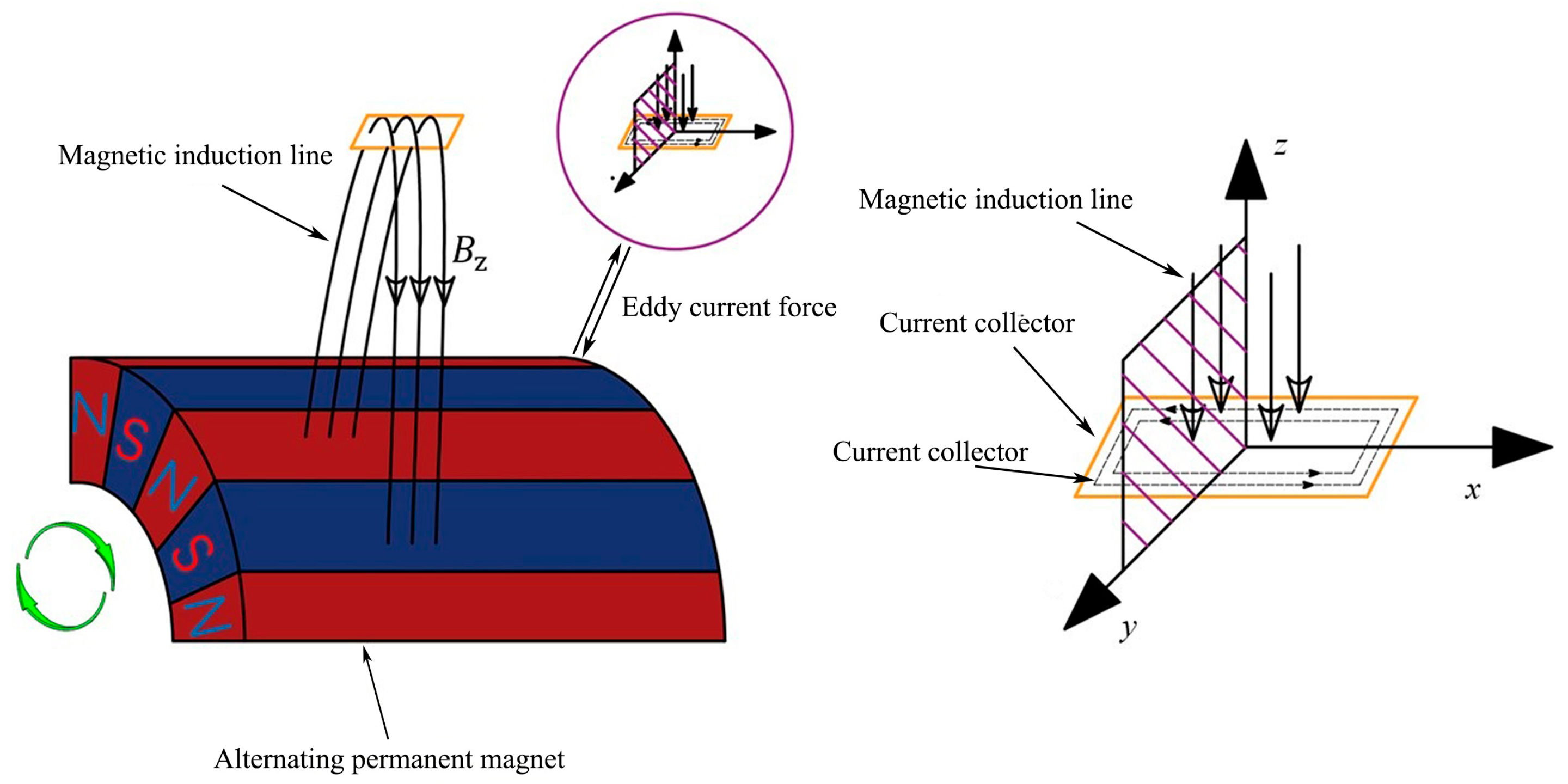
The alternating magnetic field in the sorting space of an eddy current separator is primarily excited by sector-shaped magnetic pole pairs with a high magnetic energy product. This magnetic field also rotates when the magnetic rotor is in a state of uniform rotation; thus, an alternating magnetic field distribution zone is formed. Conductive materials passing through this zone generate induced eddy currents under electromagnetic induction, which drive repulsive movements under the force of the eddy currents [28]. The principle is illustrated in Figure 1, and the distribution of magnetic induction intensity under the excitation of alternating permanent magnets can be derived using related cylindrical coordinates through a series of expansions [29].
B r = n = 0 b n ( r d / R d ) ( 2 n + 1 ) k 1 sin ( 2 n + 1 ) k ( φ ω d t ) B φ = n = 0 b n ( r d / R d ) ( 2 n + 1 ) k 1 cos ( 2 n + 1 ) k ( φ ω d t ) B Z = 0
In the equation, Br, Bφ, and BZ represent the magnetic induction strengths in the r, φ, and Z directions of the cylindrical coordinate system, respectively; rd denotes the distance from any point outside the surface of the eddy current separator’s magnetic rotor to the axis of the rotor; Rd represents the radius of the magnetic rotor; ωd denotes the rotational speed of the magnetic field; k represents the number of magnetic pole pairs; and bn represents the Fourier coefficients, which are only related to the physical properties of the permanent magnets and the order of approximation.
A three-dimensional magnetic field spatial model using alternately arranged neodymium–iron–boron permanent magnets as the magnetic field excitation source was constructed using COMSOL Multiphysics, which is multiphysics coupling software, to determine the fitting function coefficients in Equation (1). The magnetic field strength at the surface of the permanent magnets was vector-extracted, and a numerical fitting method was employed to construct the magnetic field distributions on the surface of the magnetic rotor in stationary and rotating states.
When conductive material particles enter the high-speed rotating alternating magnetic field, they passively cut through magnetic induction lines. Thus, regular induced eddy currents are formed inside the particles and a new mirror magnetic field is derived, thereby creating a corresponding repulsive force with the original magnetic field. This force is known as the eddy current force [30]. The magnitude of the eddy current force experienced by conductive material particles can be represented as follows [31]:
F z = 1 C J × k B r ( ω d R d v j ) R p V S p B 0 32 π 3 l 2 ρ R d
In the equation, vj represents the feed rate, B0 is the magnetic field strength at the surface of the magnetic rotor, Rp is the particle size of the material, V is the volume of the material, l is the distance between the material and the surface of the magnetic rotor, ρ is the material density, and CJ is the shape coefficient of the material, with the shape coefficient for standard disk-shaped materials being 1. The air resistance of the crushed products is represented as follows [32]:
F f = 6 π η a r s v
In the equation, Ff represents the air resistance experienced by the particles, ηa is the dynamic viscosity coefficient of the air in the sorting space, and v is the velocity of the particles. Once the force conditions had been defined, the physical properties of the current collector and lithium iron phosphate material, along with the magnetic field distribution function obtained from COMSOL Multiphysics 6.2, were jointly imported into MATLAB R2022b. In this way, the particles’ initial detachment angles can be solved and their motion trajectories can be fitted. Thus, a predictive model for the effectiveness of material sorting enabling the optimization of operational parameters can be established.

2.5. Eddy Current Sorting Experimental Methods

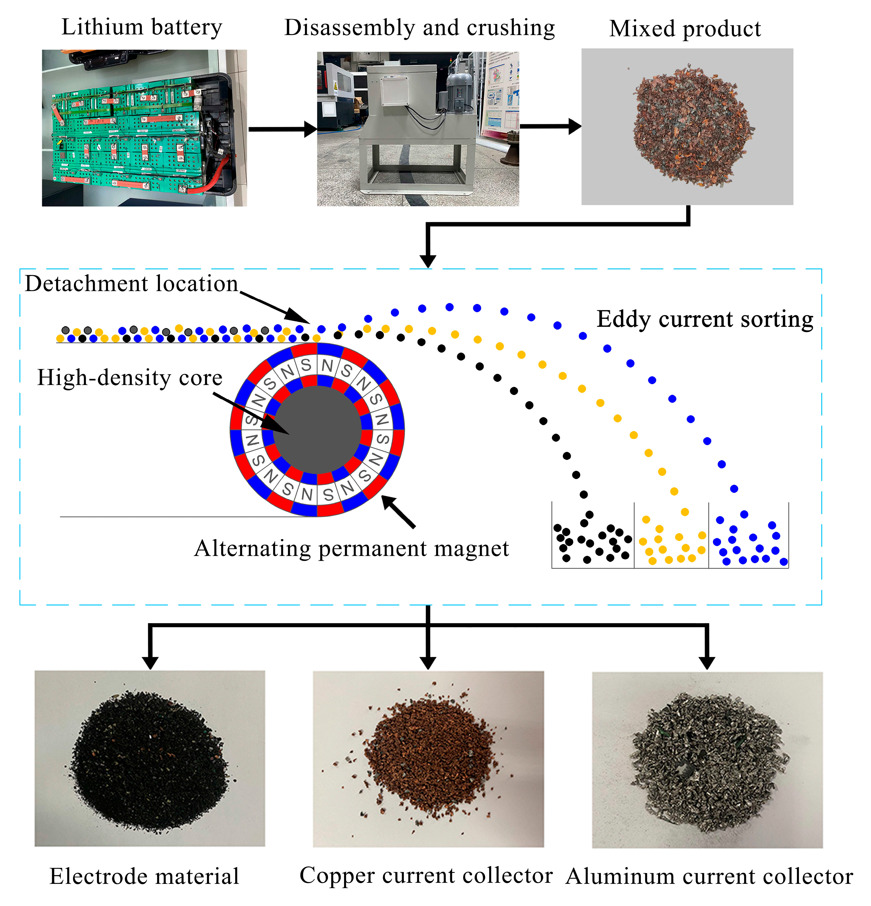
The eddy current sorting recycling process for scrapped lithium iron phosphate batteries is illustrated in Figure 2. For the sorting experiments, a TLFX model horizontal permanent magnet eddy current separator was used, which has an internal rotor composed of nine pairs of alternately arranged neodymium–iron–boron permanent magnets. The residual magnetism is 1.43 T, the outer surface diameter is 300 mm, the core diameter is 150 mm, the speed adjustment range is 0–1000 r/min, and the pulley feed speed is 50–70 r/min. Material collection and drop point location recording were completed using a grid box, which collected data on the distribution range and weight characteristics of the materials’ falling points. The separation rate and drop distance were used as indicators to conduct eddy current sorting experiments on electrode treatment products under different crushing and dissociation methods and process parameters. Each test was repeated five times to determine the average distance distribution.
The eddy current sorting samples included crushed products of various shapes and sizes. Thus, the evaluation targets were selected based on a system that utilizes the mass-weighted material sorting distance and sorting rate as indicators. Due to the weak conductivity of lithium iron phosphate materials, the sorting distance indicator for eddy current sorting uses the weighted sorting distance between copper and aluminum current collectors as a reference. The sorting distance can be calculated as follows:
D m = 1 n m Ali d i M A l 1 n m Cui d i M Cu
In the formula, Dm represents the statistical sorting distance indicator, mAli is the mass of aluminum material in the i-th grid, mCui is the mass of copper material in the i-th grid, di is the horizontal distance from the i-th grid to the center of the magnetic rotor, MAl is the total mass of aluminum material in all grids, and MCu is the total mass of copper material in all grids. The formula for calculating the sorting rate in eddy current sorting is as follows:
P t = M t m t M t
In the formula, Pt represents the sorting rate of the target product, mt is the sum of the mass of the target product in all mixed grids, and Mt is the total mass of the target product in all grids.

3. Results and Discussion

3.1. Simulation of Magnetic Field Strength in the Space Outside the Surface of Alternating Permanent Magnets

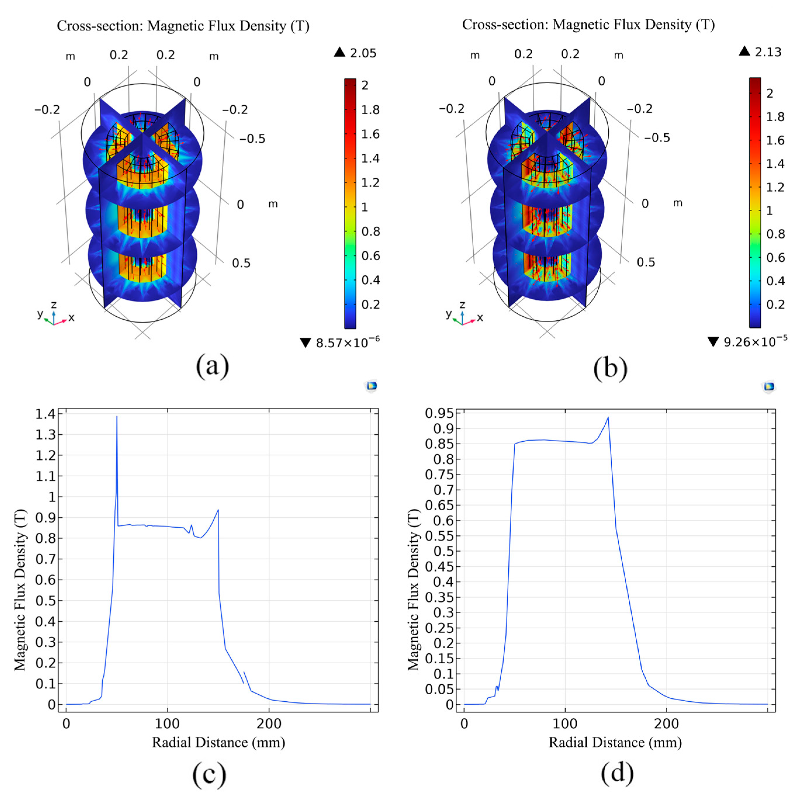
The magnetic rotor had a diameter of 300 mm, and the metal core diameter was 150 mm. Moreover, the alternating magnetic poles included nine pairs of alternately arranged neodymium–iron–boron permanent magnets. The simulation results for the magnetic flux density distribution on the surface of static permanent magnets obtained in COMSOL are shown in Figure 3a, with the direction of the magnetic field indicated by arrows. The simulation results indicate that the magnetic field near the outer surface of the magnetic rotor is arranged alternately and uniformly. The peripheral magnetic field of the alternating permanent magnets is a periodic finite element magnetic field, and the magnetic field strength decreases with increasing distance from the surface of the permanent magnet. Additionally, the magnetic permeability of the gas medium in the sorting space is weak; thus, the magnetic field strength decays significantly within this range, with high-intensity magnetic fields primarily concentrated in a smaller spatial area close to the surface of the alternating magnetic rotor. A sudden change in the magnitude and direction of the field strength occurs at the junction of the S and N magnetic poles on the rotor surface.
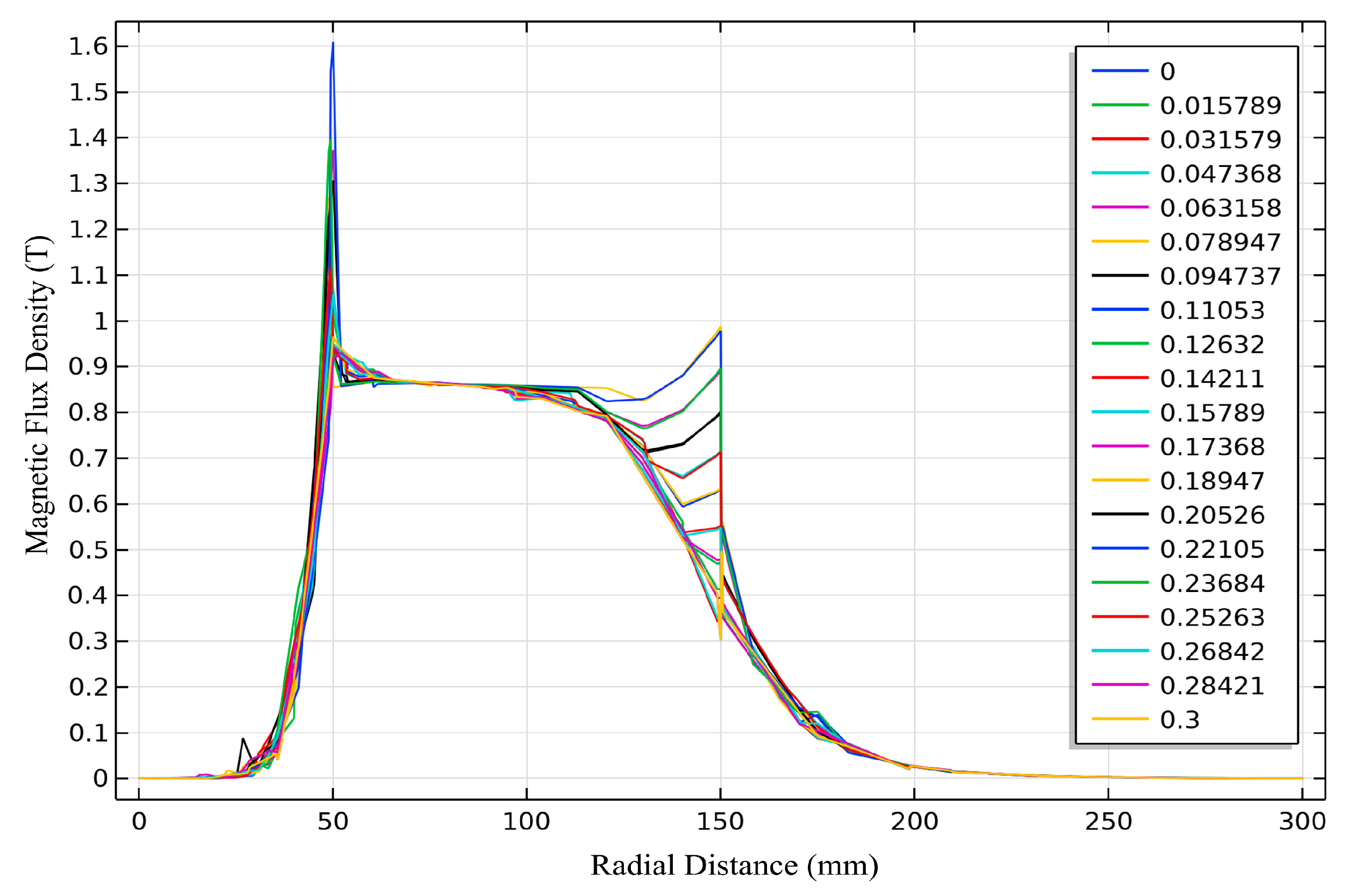
The relationship between the magnetic field strength at the junction of the magnetic poles on the outer surface of the magnetic rotor and the spatial distance, with the radial outward direction chosen as the reference, is shown in Figure 3c, while the relationship between the magnetic field strength in the direction of the N magnetic pole of the rotor and spatial distance is depicted in Figure 3d. The substantial changes in magnetic field strength and distribution as the spatial position transitions along the circumferential direction (from Figure 3c to Figure 3d) provide a basis for the alternating change in magnetic flux for conductive materials moving within the magnetic field. A uniform counterclockwise rotational motion was applied to the permanent magnet rotor model to generate a stable dynamic alternating magnetic field in the sorting space. Figure 3b shows the transient magnetic field distribution in the space around the rotor when the permanent magnet rotates at a speed of 400 r/min. During rotation, the external magnetic field strength exhibits periodic changes due to the alternating influence of the magnetic pole pairs. The cross-section at the central point along the rotor axis was selected as the reference plane for analysis, and the relationship between the magnetic field strength within this plane and the changes in spatial distance and time is shown in Figure 4.
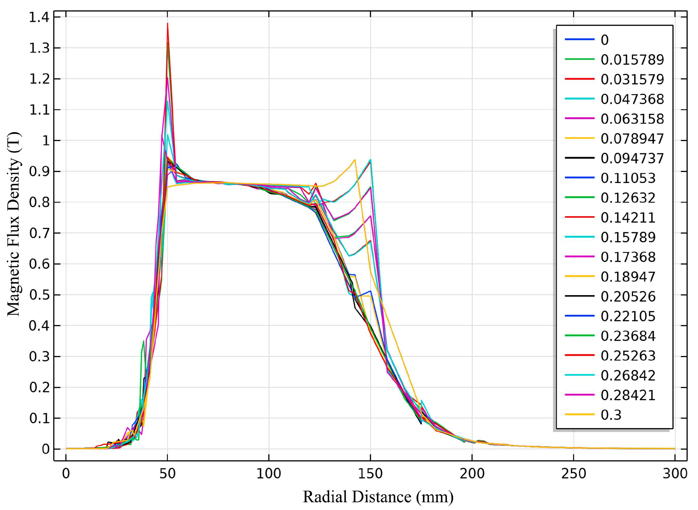
The results indicate that the magnetic field distribution in the external space of the magnetic rotor changes in a relatively regular manner over time. The range and rate of periodic changes in the magnetic field intensity reach their maximum values near the surface of the magnetic rotor (at the 150 mm position in Figure 4), with a variation range of 0.306 to 0.972 T and a maximum transient rate of change of 133.617 T/s. When the rotational speed of the magnetic field is increased in the model, the magnetic field intensity distribution remains consistent with that in Figure 4; however, the density between the distribution curves increases. This finding indicates that although increasing the rotation speed of the permanent magnet does not enhance the magnetic field intensity, this approach can increase the rate of change of the magnetic flux on the surface of the induced conductor by increasing the alternating frequency of the magnetic field direction. This scenario is beneficial for the formation of induced currents within the conductor. Additionally, an increase in the magnetic field’s alternating frequency reduces the equivalent period of the equivalent magnetic field intensity, resulting in uniform changes in the induced current when the conductor moves in the magnetic field. This phenomenon helps to reduce the degree of force dispersion among particles of the same type.
The xy reference plane shown in Figure 3b was adjusted to move along the axial direction (z-axis) to examine the variation in the spatial distribution of the magnetic field outside the magnetic rotor in relation to its axial position. When the movement range remains within 94.3% of the axial length, the pattern of the spatial magnetic field distribution in any reference plane aligns with that depicted in Figure 4, while the magnetic field distribution begins to show signs of attenuation and dispersion when the range exceeds 94.3% of the axial length. Figure 5 illustrates the distribution of the magnetic field on the axial edge cross-section of the magnetic rotor. Compared with the field strength at the central cross-section, that at the shaft end attenuates. Moreover, the peaks of magnetic field strength display a staggered trend spatially and temporally, which significantly impacts the variation in magnetic flux within the materials being sorted. As a result, the formation of a stable induced eddy current field is inhibited and the efficacy of the sorting process is diminished. Consequently, the material feed must be maintained within 94.3% of the axial range of the magnetic rotor during the sorting operation.

3.2. Degradation Model of Conductive Performance in Waste Cathode Materials

3.2.1. Elemental Migration Characterization of Waste Lithium Iron Phosphate Materials

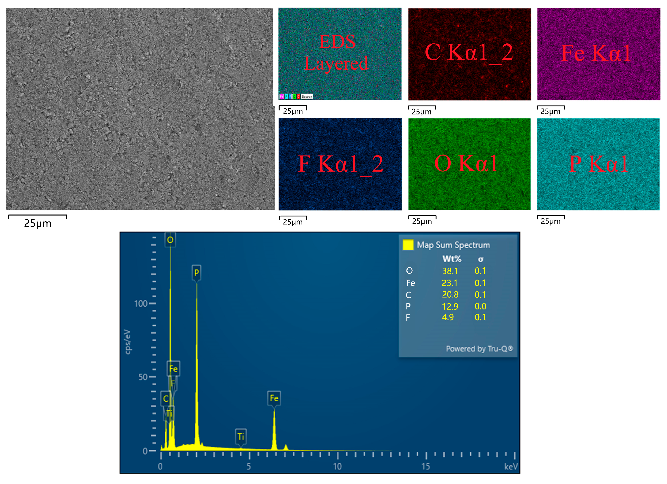
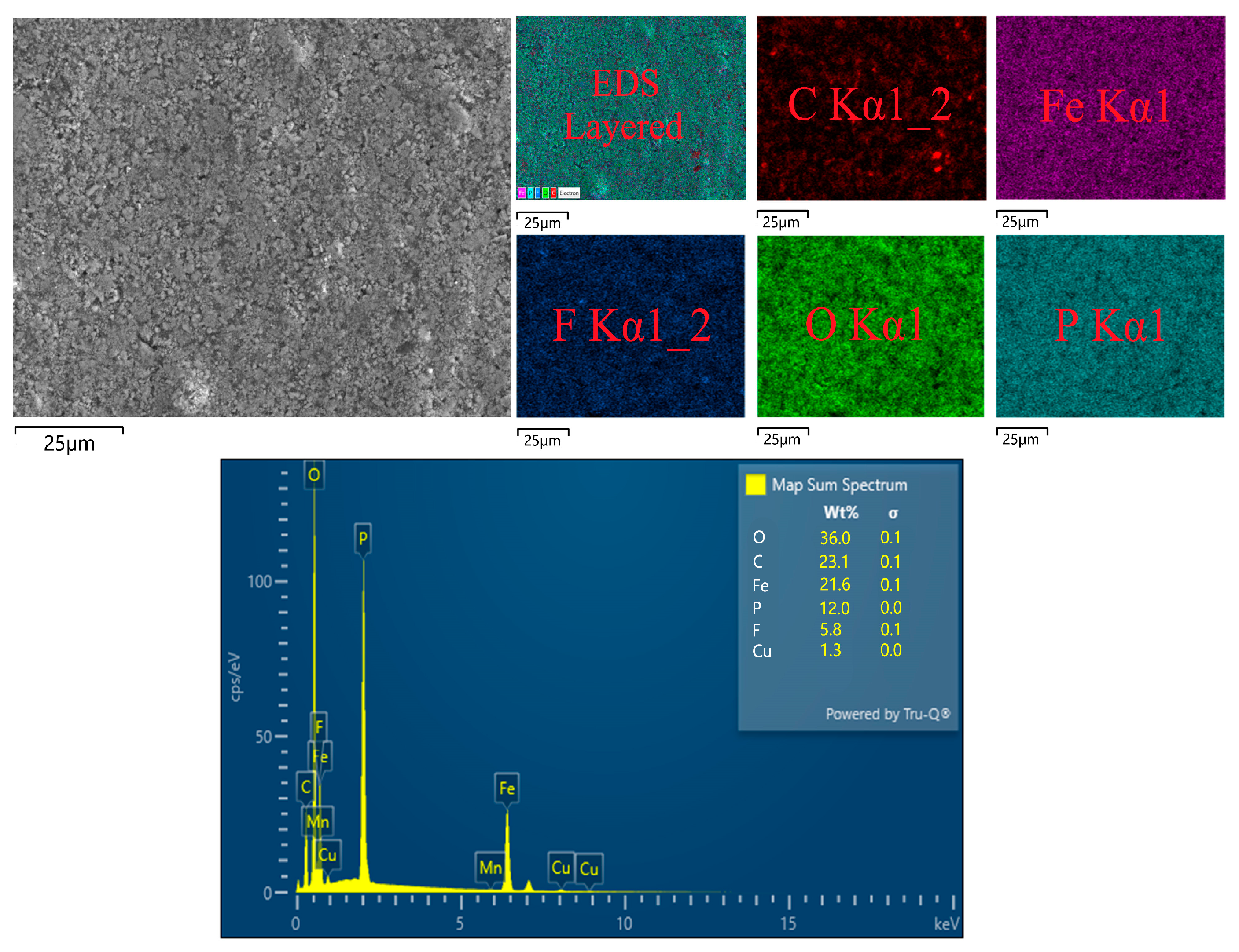
SEM-EDS techniques were employed to analyze the surface composition of cathode materials from lithium iron phosphate battery production waste and batteries discarded after long-term charge–discharge cycles, with the results shown in Figure 6 and Figure 7. The characterization results reveal that the surface of the cathode sheets from production waste, which have not been used in cycles or subjected to external mechanical forces, is relatively smooth. Moreover, the distribution of elements on the surface is relatively uniform, with minimal corrosion. In contrast, the surface structure of the cathode sheets from batteries that have been cycled is relatively loose, indicating signs of corrosion. The increase in the proportion of carbon elements is attributed to cross-contamination between the binder PVDF and the anode graphite material, while the increase in fluorine elements stems from the decomposition of the electrolyte and PVDF, which contributes to corrosion. The presence of copper elements originates from cross-contamination with copper from the anode current collector.
Previous studies have indicated that the conductive performance and cycling performance of lithium iron phosphate battery electrodes degrade after prolonged use; this outcome is particularly evident in the physical and chemical properties of the electrode coating materials [33]. Therefore, the physical properties of lithium iron phosphate materials in the eddy current sorting process cannot be directly simulated using theoretical values; instead, precise resistivity measurements of the cathode materials from waste lithium batteries must be conducted after cycling to accurately predict the trajectories of the crushed products in an alternating magnetic field.

3.2.2. Analysis of Resistivity Measurement Results

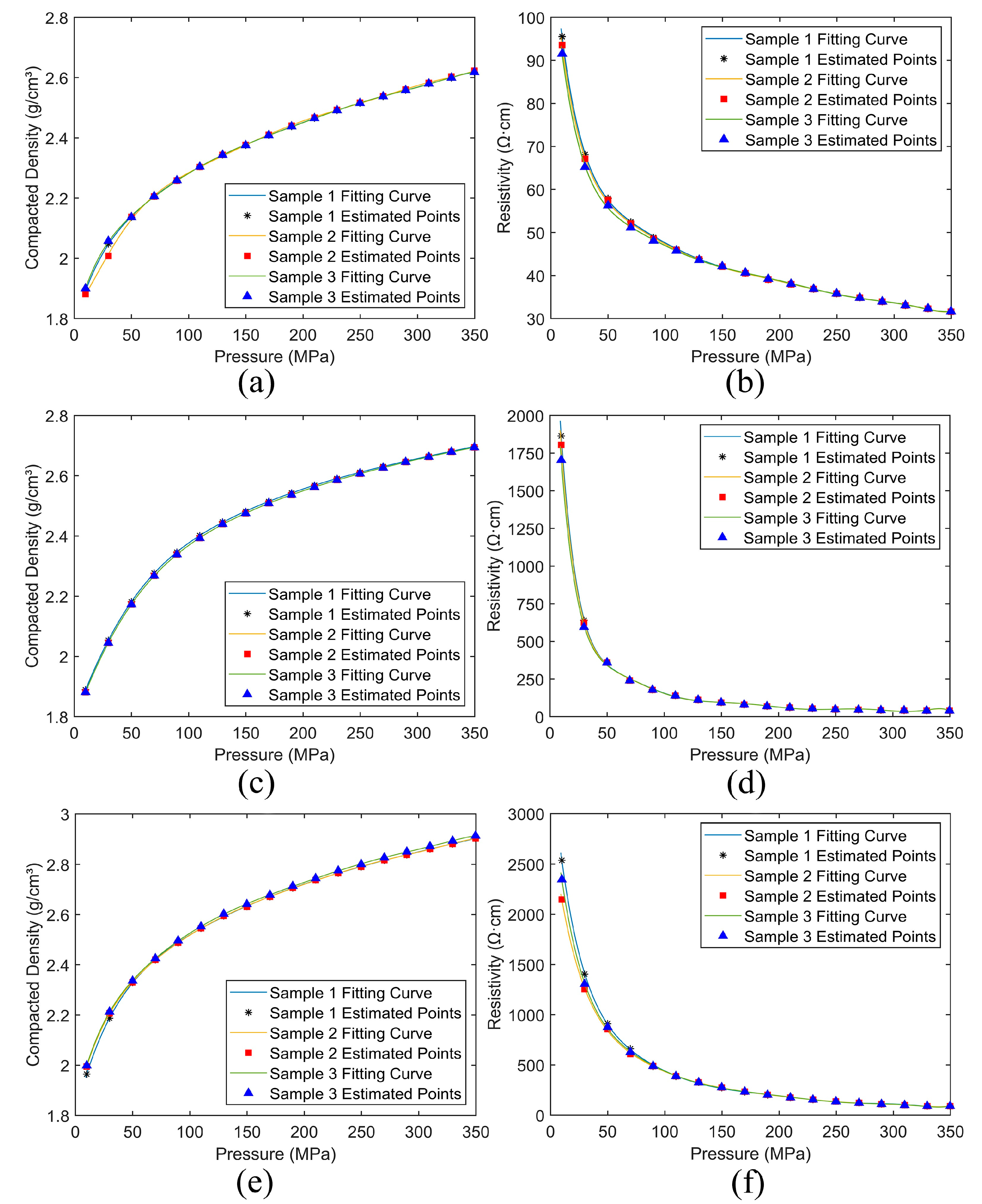
Figure 8 illustrates the resistivity and compaction density curves of cathode materials from three sources as functions of surface pressure. The three materials exhibit similar mechanical and conductive properties, and the compaction density of each sample group increases with increasing surface pressure; however, the rate of this increase slows down gradually. In contrast, the resistivity of the three groups of cathode material samples decreases progressively with increasing surface pressure. The reason for this observation is that the particle spacing is relatively large for cathode materials in a loose state, resulting in weak electron transport capability between particles. As the external pressure increases, the contact paths between the cathode material particles become successively conductive, gradually restoring the electron transport capability. This phenomenon leads to a simultaneous decrease in resistivity for each group of materials.
Figure 8b shows that even within the initial pressure application range, the resistivity of the production waste sample group is already within the range of 100 Ω·cm, which is significantly lower than that of the two other material groups. This is because conductive additives are incorporated into the production waste, and the particles are tightly bonded by the binder. This ensures that the production waste material maintains relatively highly conductive contact paths, thereby reducing electron transport resistance even in the absence of applied external pressure.
As the external pressure gradually increases, the resistivity differences between various materials quickly diminish, except for the initial pressurization stage where certain variability is observed due to powder aggregation. In the standard compaction density range (2.2–2.5 g/cm3), the conductivity of the three groups of electrode materials consistently presents the following order: production waste > high-purity lithium iron phosphate > waste cathode materials. Moreover, their resistivities converge to approximately 38, 45, and 89 Ω·cm, respectively. This finding indicates that the mechanical recycling method effectively maintains the structural integrity of the cathode materials; however, recycled electrode materials still need to undergo separation and purification processes along with the crushed products from the current collectors. The slow reduction in the resistivity of the production waste samples is due to the combined effects of particle aggregation caused by the binder and particle contact under external pressure. The resistivity of the production waste samples remains lower than that of the high-purity lithium iron phosphate samples due to the addition of conductive materials, such as carbon black or carbon nanotubes, during the cathode material production process.
The resistivity of the materials further decreases when the compaction density of each sample group reaches 2.5 g/cm3 and the surface pressure continues to increase; however, the rate of this decrease significantly diminishes, resulting in a minimal impact. Previous studies have shown that although the physical contact between particles can be further enhanced at a high compaction density of the cathode material, excessive compaction may lead to particle structure damage and a reduction in the porosity of the electrode [34]. Such a reduction in porosity can limit the permeability of the electrolyte and affect the diffusion rate of lithium ions, thereby degrading the charge–discharge performance of the battery [35]. Moreover, excessively high compaction density may cause the electrode materials to be highly prone to cracking during long-term use, further impacting the stability and lifespan of the battery. Therefore, during the mechanical recycling of waste lithium battery cells, the pressure should be controlled within a reasonable range.
The results of the conducted tests indicate that the conductivity of the lithium-ion battery cathode electrode degrades significantly with long-term use. Based on the SEM characterization results shown in Figure 6 and Figure 7, this may be attributed to the high resistivity of the natural oxide film on the current collector which, during aging, thickens or undergoes compositional changes, leading to a significant increase in interface and contact resistance. Additionally, the decomposition of LiPF6 (the electrolyte) produces HF over prolonged usage, which promotes the dissolution and redeposition of transition metals, accelerates surface side reactions, and results in more complex inorganic or organic residual layers forming on the surface of the current collector and cathode material particles, thereby increasing the equivalent resistance [36]. Furthermore, the formation of particle cracks in the lithium iron phosphate material during cycling or the Fe dissolution–redeposition phenomenon occurring at higher temperatures can also lead to declines in effective conductivity [37].

3.3. Calculation of Conductor Materials’ Initial Detachment Position

As the conductor materials approach the magnetic rotor, the intensity of the induced eddy currents within them gradually increases. The materials begin to detach from the conveyor belt and enter a projectile motion when the eddy current force exceeds the gravitational force. Given the rotational movement characteristics of the magnetic rotor, the angle θ between the conductor particle–magnetic rotor center line and the vertical direction is introduced as an indicator of material advancement. The larger the θ value is at the moment of detachment, the earlier the material detachment sequence. The formula defining θ is as follows:
θ = arccos ( l R )
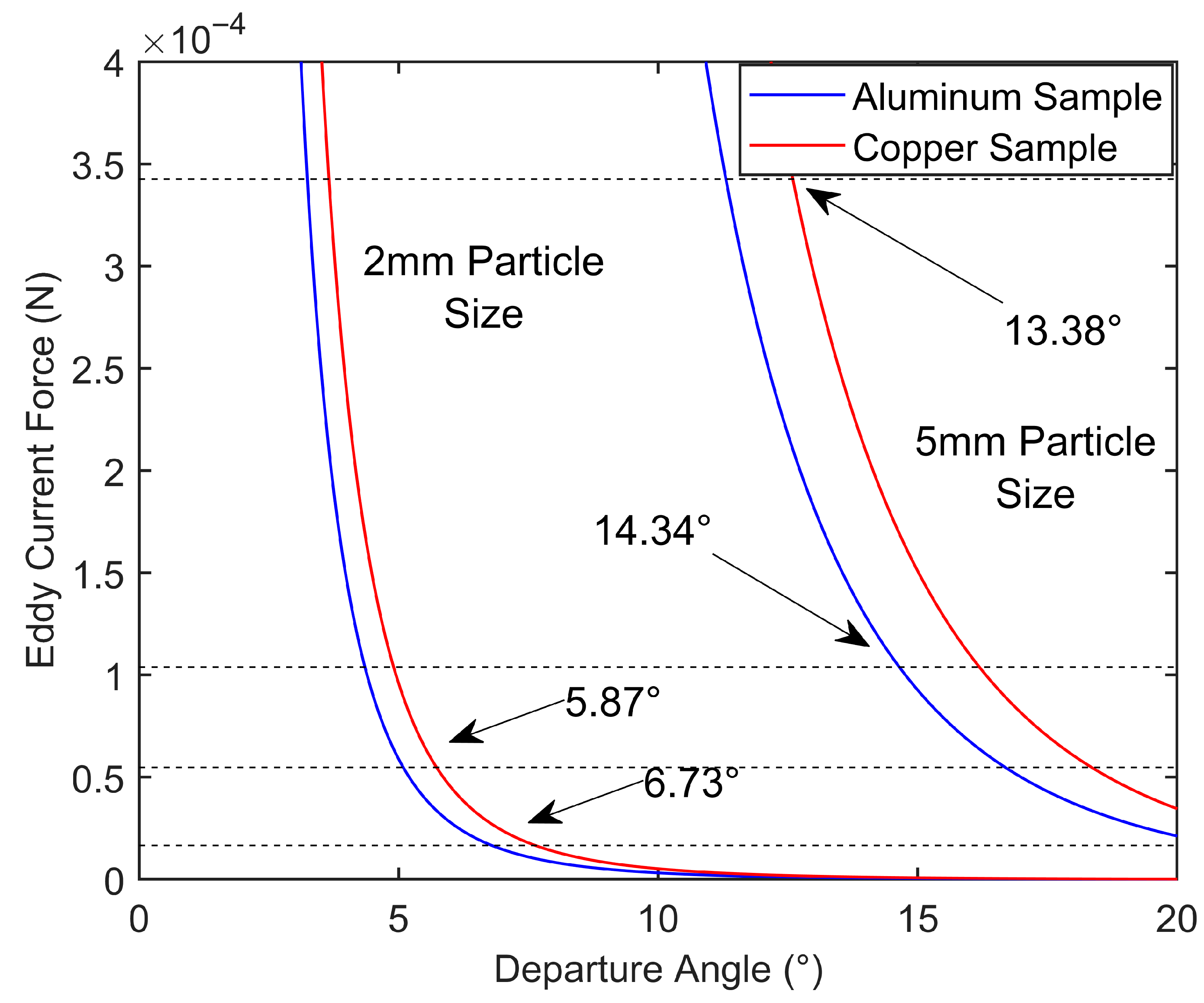
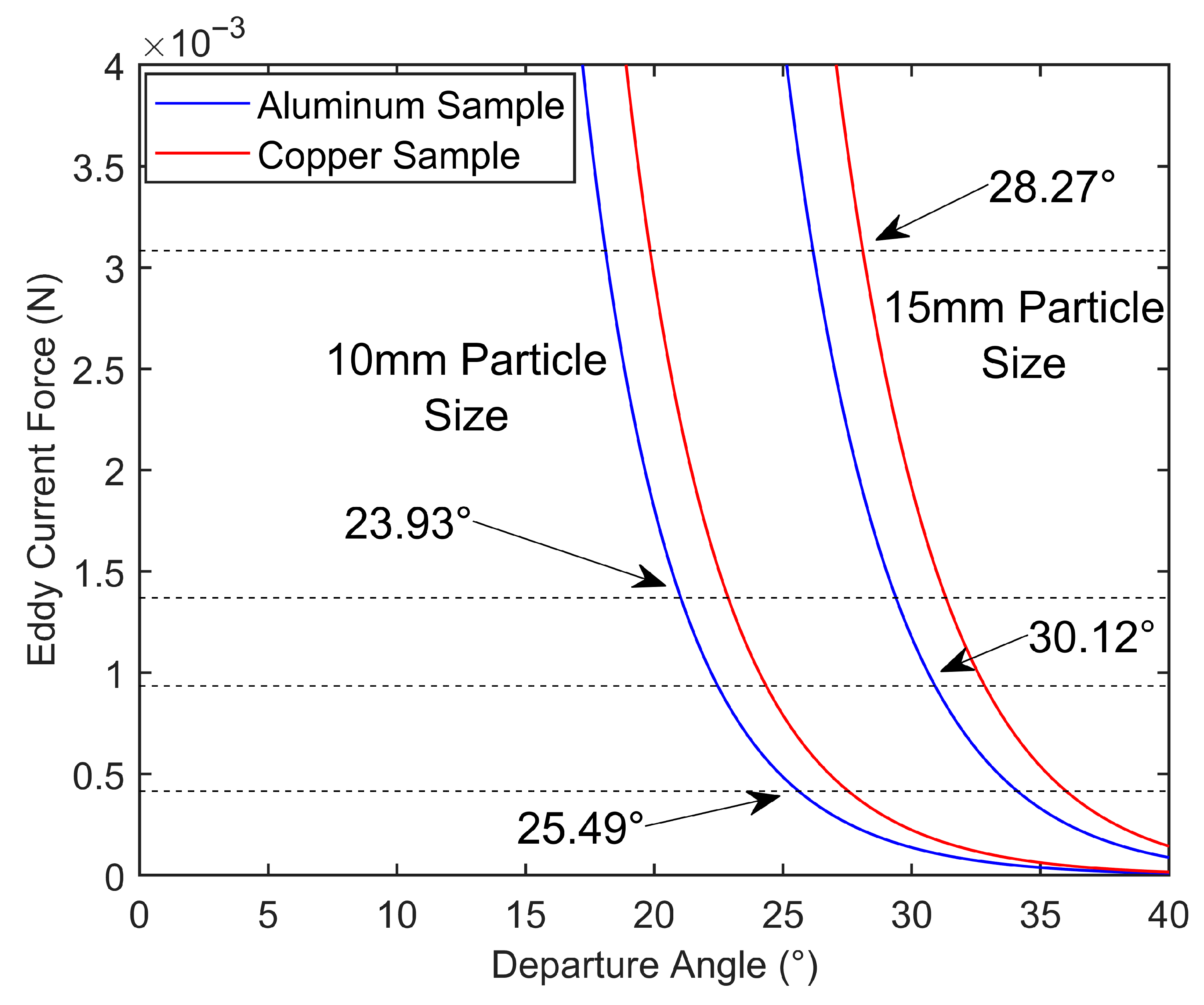
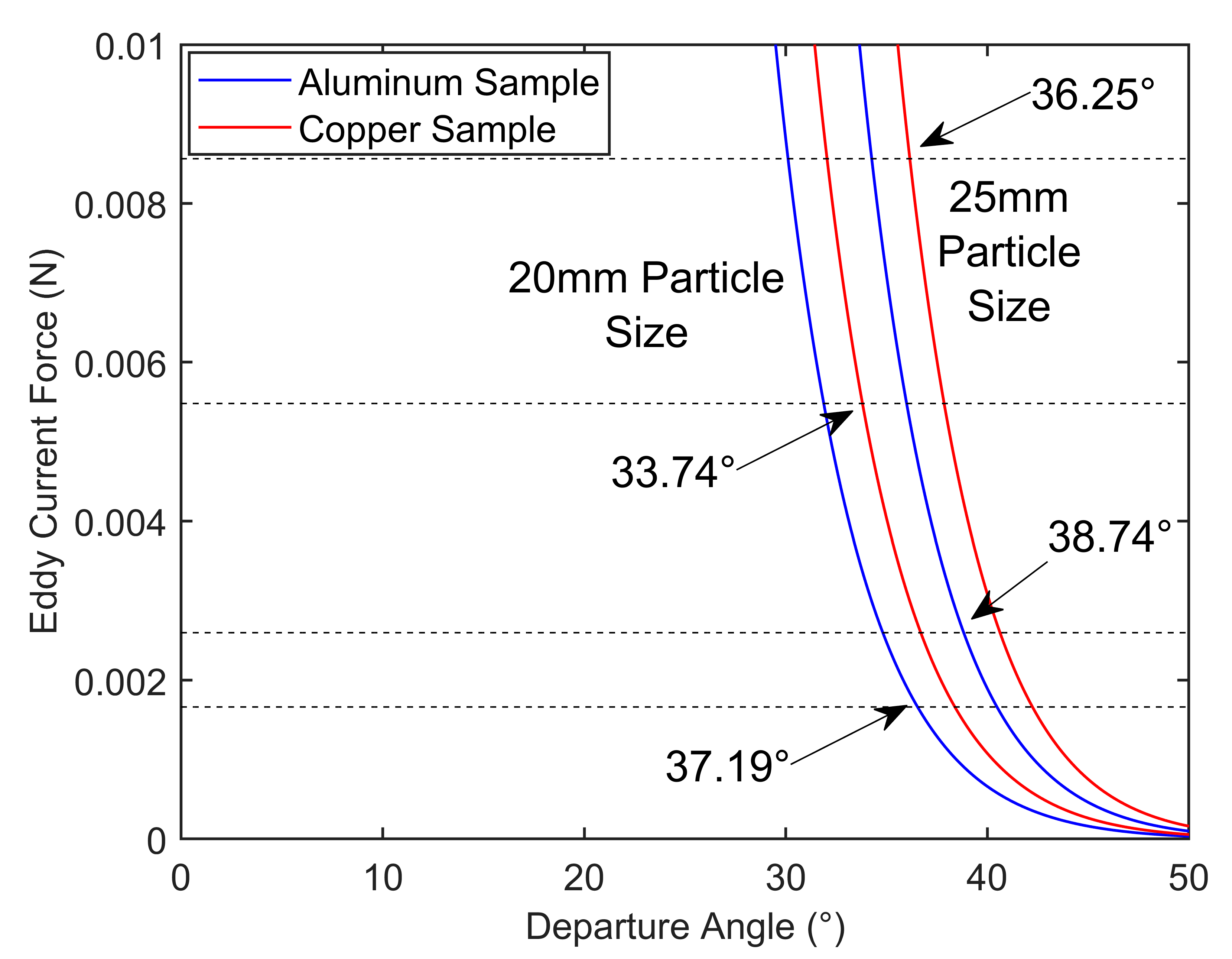
The variation in the eddy current force experienced by the crushed products in the alternating magnetic field with respect to their advancing position is shown in Figure 9, Figure 10 and Figure 11. The horizontal lines in the figures represent the gravitational force on each material particle. The intersection points between the force function curves for each material and the gravitational horizontal line indicate the critical state where the eddy current force exactly counteracts the gravitational force. This point represents the critical position at which the conductor material detaches from the conveyor belt and enters the next stage of motion. The resistivity of lithium iron phosphate was selected based on the test results for waste lithium iron phosphate products with a compaction density of 2.5 g/cm3 (89 Ω·cm), as shown in Figure 8f. However, unlike the copper and aluminum materials, the resistivity of the lithium iron phosphate exceeds seven orders of magnitude; thus, it cannot be simultaneously marked in the figure. As such, its detachment state is independently analyzed in Section 3.4.
The analysis results in Figure 9 show that as the angle θ approaches 0° (i.e., the material comes close to the alternating magnetic rotor), the eddy current force experienced by the material undergoes a sudden change within a specific range; it rapidly exceeds the material’s gravitational force, leading to a detachment and leap phenomenon. Additionally, the eddy current force increases synchronously with the particle size of the material. The reason for this is that a large volume can accommodate a highly substantial and dense induced current; thus, a strong induced magnetic field is generated, resulting in a great eddy current force on the material. Although the gravitational force of the conductor material also increases with volume, the associated rate of increase is lower than that of the eddy current force. Therefore, the critical detachment angle of the conductor material also increases as the particle size increases. This phenomenon facilitates the early detachment of particles from the conveyor belt, thereby leading to differentiated motion trajectories based on their conductivity.
The analysis results in Figure 9 and Figure 10 demonstrate that increasing the particle size increases both the detachment angle of various conductor materials and the difference in detachment angles between materials. This phenomenon promotes differentiated motion trends at the initial motion stage, positively influencing the subsequent layered leap trajectories. Furthermore, the detachment position on the conveyor belt advances significantly when the particle size of the conductor materials increases from 5 to 10 mm. This finding indicates that a particle size exceeding 5 mm provides an effective guarantee for the materials to achieve a substantial eddy current leap motion.
When the diameter of the sheetlike conductor materials reaches 20 and 25 mm, the eddy current force and the corresponding detachment angle continue to increase by further increasing the particle size; however, the growth trend noticeably slows down. This finding indicates a boundary effect in the influence of particle size growth on the early detachment effect in eddy current sorting. Although the critical detachment angles for aluminum and copper materials continue to increase, the difference in detachment angle between the two materials begins to decrease. This finding suggests that continuously increasing the particle size of the materials to be sorted alone does not achieve the optimal separation effect. Given that excessively large target diameters are difficult to control precisely in the crushing and screening processes, a particle size of 20 mm should be the optimal target diameter for the separation of mixed current collector materials from the perspective of detachment position.
The detachment angle calculation results for aluminum and copper materials show that the detachment angle range for aluminum fragments of various sizes in eddy current sorting is 6.73–38.74°, whereas that for copper fragments of various sizes is 5.87–36.25°. Under the same conditions, the detachment angles for aluminum fragments are consistently higher than those for copper fragments, indicating that aluminum fragments detach from the conveyor belt with minimal difficulty and in a prompt sequence. The reason for this is that although copper has a lower resistivity than aluminum, the density of copper is significantly higher than that of aluminum. Consequently, the eddy current force required for copper fragments to detach from the conveyor belt is much greater than that for aluminum fragments, making detachment more challenging for copper.

3.4. Trajectory Fitting of Conductor Materials in Alternating Magnetic Fields

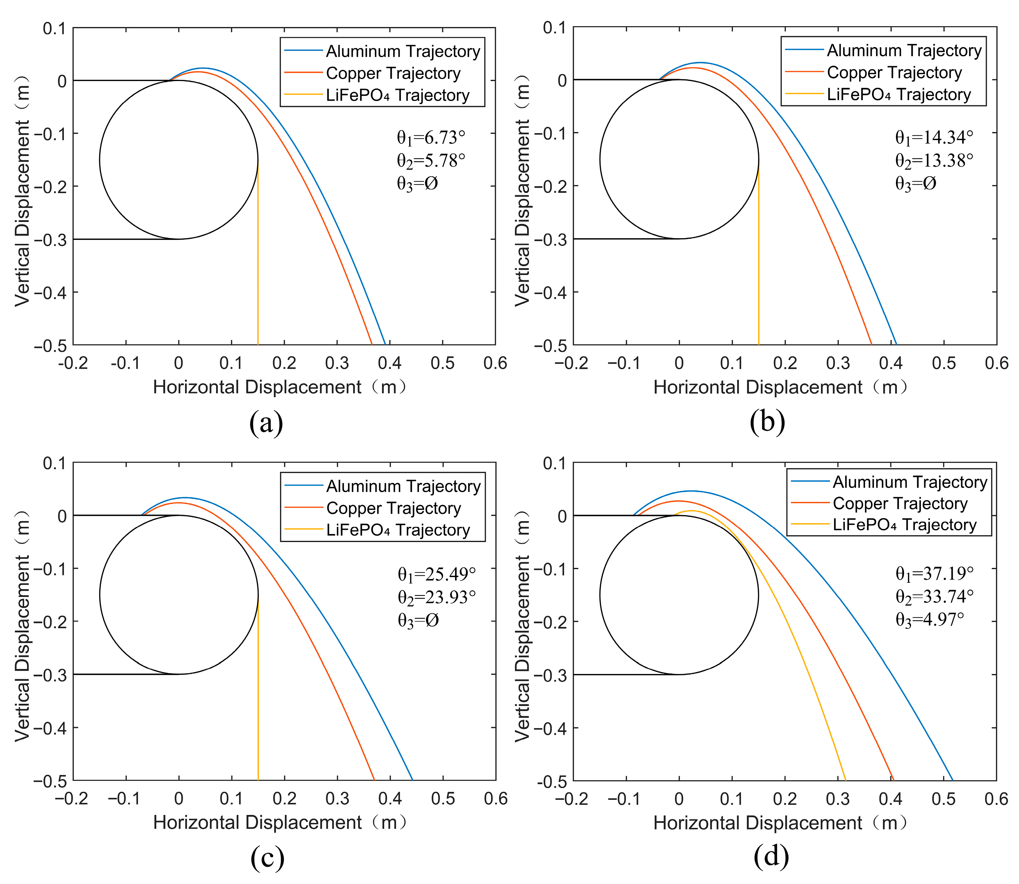
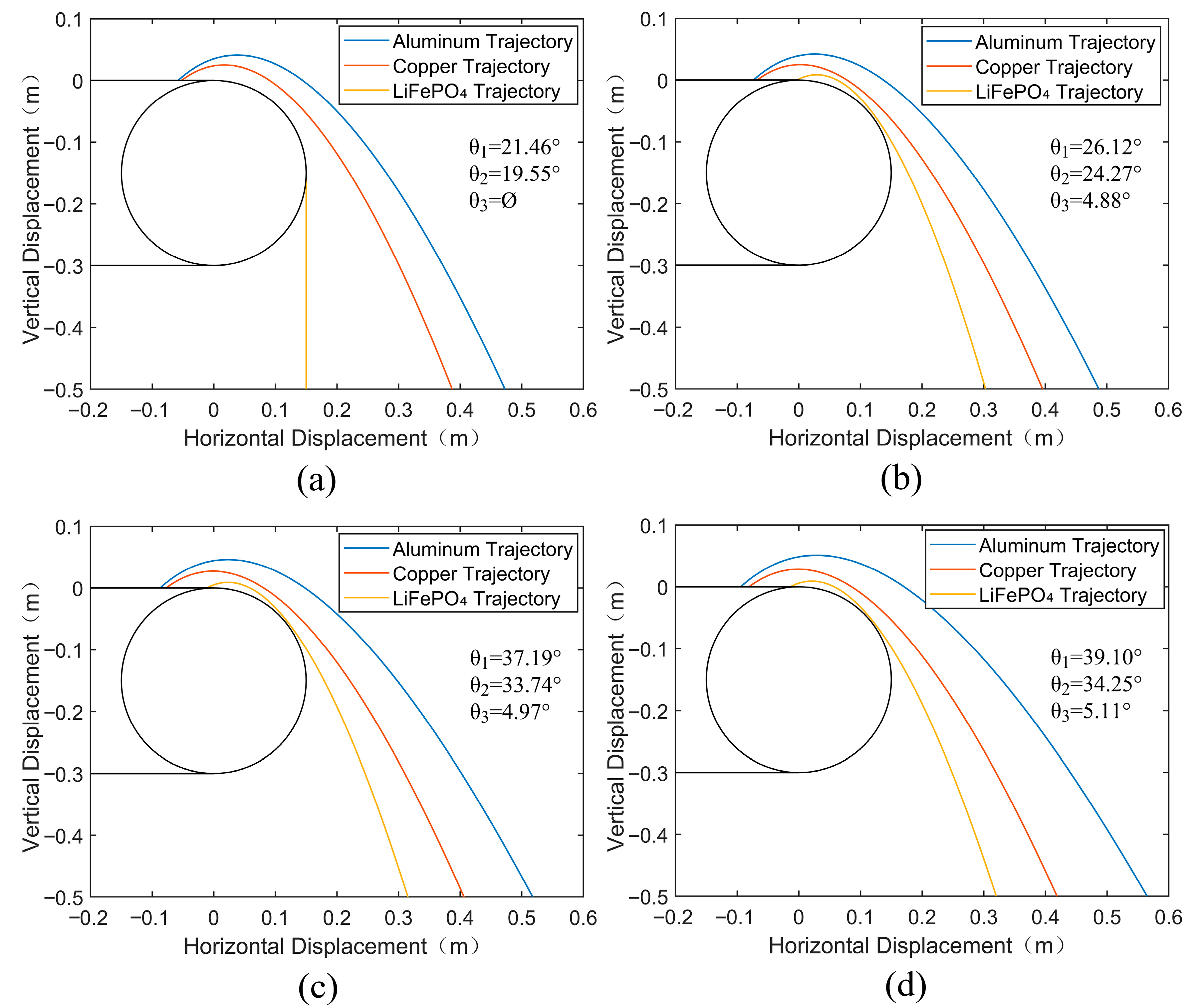
Based on the critical detachment state, the initial detachment positions and the initial forces during the leap motion of the conductor materials were input into MATLAB to simulate the trajectories of the materials. The magnetic field strengths on the outer surface of the magnetic rotor and within the separation chamber space were derived from the fitting results shown in Figure 3. The iteration time step was 1 × 10⁻⁵ s, the fall height was 0.4 m, the number of alternating magnetic pole pairs was 9, the magnetic rotor speed was 800 r/min, the feed speed was 60 r/min, and the material particle size ranged from 2 to 20 mm. The simulated separation trajectories of the crushed particles from lithium iron phosphate batteries in the alternating magnetic field are shown in Figure 12. In the figure, θ1, θ2, and θ3 represent the critical detachment angles for aluminum, copper, and lithium iron phosphate, respectively, and the large circle represents the roller contour. Furthermore, Ø indicates that even when the material is directly above the alternating magnetic rotor, it does not generate an eddy current detachment motion; as such, its motion trajectory remains similar to that of non-conductive particles.
The trajectory fitting results in Figure 12 demonstrate that the theoretical trajectories of various components of the crushed lithium iron phosphate battery materials exhibit distinct differentiation characteristics, providing ample physical conditions for the subsequent electromagnetic separation of these materials. The horizontal displacement order of the landing points for the materials is aluminum > copper > lithium iron phosphate. While copper and aluminum particles exhibit similar motion characteristics in the alternating magnetic field, the density of copper is much higher than that of aluminum; thus, the impact of eddy current forces on copper is small, resulting in a shorter leap distance in the alternating magnetic field. In contrast, lithium iron phosphate, with its relatively poor conductivity, approximates a free-fall trajectory along the edge of the magnetic rotor.
The material trajectories were refitted within the magnetic rotor speed range of 400–1000 r/min using the optimized particle size parameter of 20 mm to further verify the impact of magnetic rotor speed on the separation trajectories of the current collector materials, with the results shown in Figure 13. Although lithium iron phosphate materials do not exhibit a detachment effect at magnetic rotor speeds lower than 400 r/min, theoretical detachment motion is observed at magnetic rotor speeds of 600–1000 r/min; however, the detachment trajectories of the lithium iron phosphate materials closely adhere to the edge of the roller. This phenomenon results in a high probability of collision with the roller. Given the unique structural properties of lithium iron phosphate particles, fragments larger than 10 mm in diameter are difficult to obtain regardless of the crushing process [38]. Therefore, these materials primarily exhibit free-fall motion even in a high-speed rotating magnetic field. The motion trajectories of the current collector materials in the crushed and dissociated products shift in the positive horizontal direction with increasing magnetic rotor speed, and their landing positions shift accordingly. This finding confirms the promoting effect of magnetic field speed on the separation motion. Given the high-density characteristics of copper materials, an increase in magnetic field speed has a weak promoting effect on their landing distance; in contrast, it has a strong effect on aluminum materials. Therefore, increasing the magnetic rotor speed can enhance the separation distance between these two materials, thereby further improving their separation efficiency.

3.5. Eddy Current Separation Experiment

In the eddy current separation experiment, the landing points of the lithium iron phosphate materials were consistently distributed at the nearest grid point regardless of how the operating parameters were set. This finding indicates that lithium iron phosphate materials with significantly degraded conductivity should be considered as non-conductive materials in the eddy current separation process, which is consistent with the simulation results. The landing point statistics for copper and aluminum materials from the ball-milled positive and negative current collectors are shown in Table 1, Table 2, Table 3 and Table 4.
The separation distance and separation rate of the materials increase with the particle size and the rotational speed of the alternating magnetic rotor, again consistent with the theoretical fitting results. In contrast, increasing the conveyor belt speed has little effect on the separation rate. This is mainly because an increase in the feed rate also raises the initial horizontal velocity of the materials during the transition movement, which does not increase the distance between the drop points of different materials. Furthermore, excessive feed speed accelerates material collisions during the eddy current sorting process, negatively affecting the separation efficiency. The eddy current sorting device used in this experiment has a pulley speed range of 50–70 r/min, which is much lower than the magnetic rotor speed (200–1000 r/min), thus minimizing material collisions caused by excessive feed speed during the initial design phase. Additionally, in our experiment, we used manual feeding (large particle size) and vibration sieves (small particle size) to feed the conveyor belt, resulting in single-layer feeding with relatively low density, which is another reason why the collision effect was minimal. Therefore, in industrial production, special attention should be paid to the feed speed.
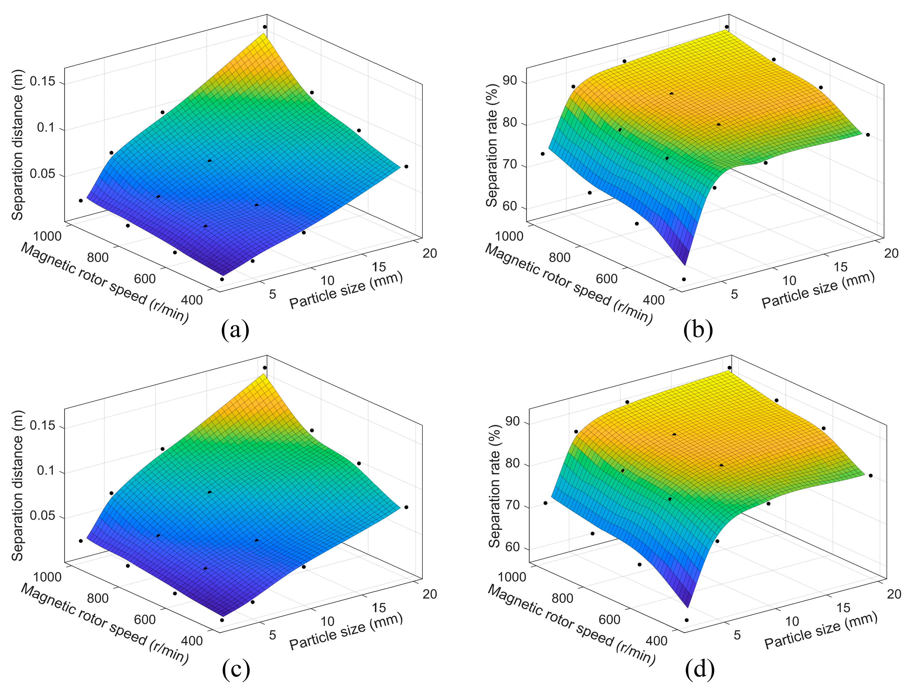
To further investigate the effects of the interaction between magnetic rotor speed and material particle size on the separation distance and separation rate, a three-dimensional response surface plot was constructed based on the experimental data (Figure 14), which shows that under all conditions, the separation performance increases monotonically with the magnetic rotor speed and material particle size. Moreover, particle size and magnetic rotor speed present a coupled effect on the separation distance: at higher speeds, an increase in the particle size leads to a more significant increase in separation distance. This is because higher alternating magnetic field frequencies can support larger volumes of material, generating more extensive eddy currents within them. However, this coupled enhancement effect brought about by an increase in magnetic rotor speed exhibits more pronounced boundary effects in regions with a higher separation rate. Considering the associated increase in energy consumption, it is important to optimize the uniformity of the dissociated material’s shape and the particle size consistency as process improvement parameters, rather than blindly increasing the magnetic rotor speed. Furthermore, while Figure 14a–d correspond to lower and higher feed speeds, respectively, the response surfaces are almost identical, indicating that the feed speed (within a reasonable range) does not have a coupled effect on separation rate with other parameters.
The statistical results indicate that when the magnetic rotor speed is 1000 r/min and the particle size is 20 mm, the optimal separation effectiveness is achieved, which is consistent with the theoretical simulation results. Under these conditions, the experimentally measured average separation distance was 0.162 m, with a deviation of 8.9% from the theoretical value. Multiple separation experiments were conducted with the current collector and electrode materials under these conditions, and the single-pass eddy current separation rates for aluminum, copper, and lithium iron phosphate were 90.2%, 91.9%, and 95.1%, respectively. Based on these results, secondary and tertiary eddy current separation was performed on the products recovered from grids containing mixed materials in the material collector. The overall secondary separation rates for the three materials reached 93.1%, 93.9%, and 95.9%, while the tertiary separation recovery rates reached 93.9%, 94.6%, and 96.1%, respectively. Although the recovery rates for each material increased with the number of separation passes, the single-pass separation rate significantly declined. Through observation of the collection results for multiple eddy current separations, this phenomenon was considered to mainly be due to the extremely irregular shapes of some crushed products, which remained difficult to separate even after multiple eddy current separations. This finding indicates that achieving an optimal particle size and ensuring the regularity and consistency of the crushed products are important when selecting the crushing method for waste lithium iron phosphate batteries.
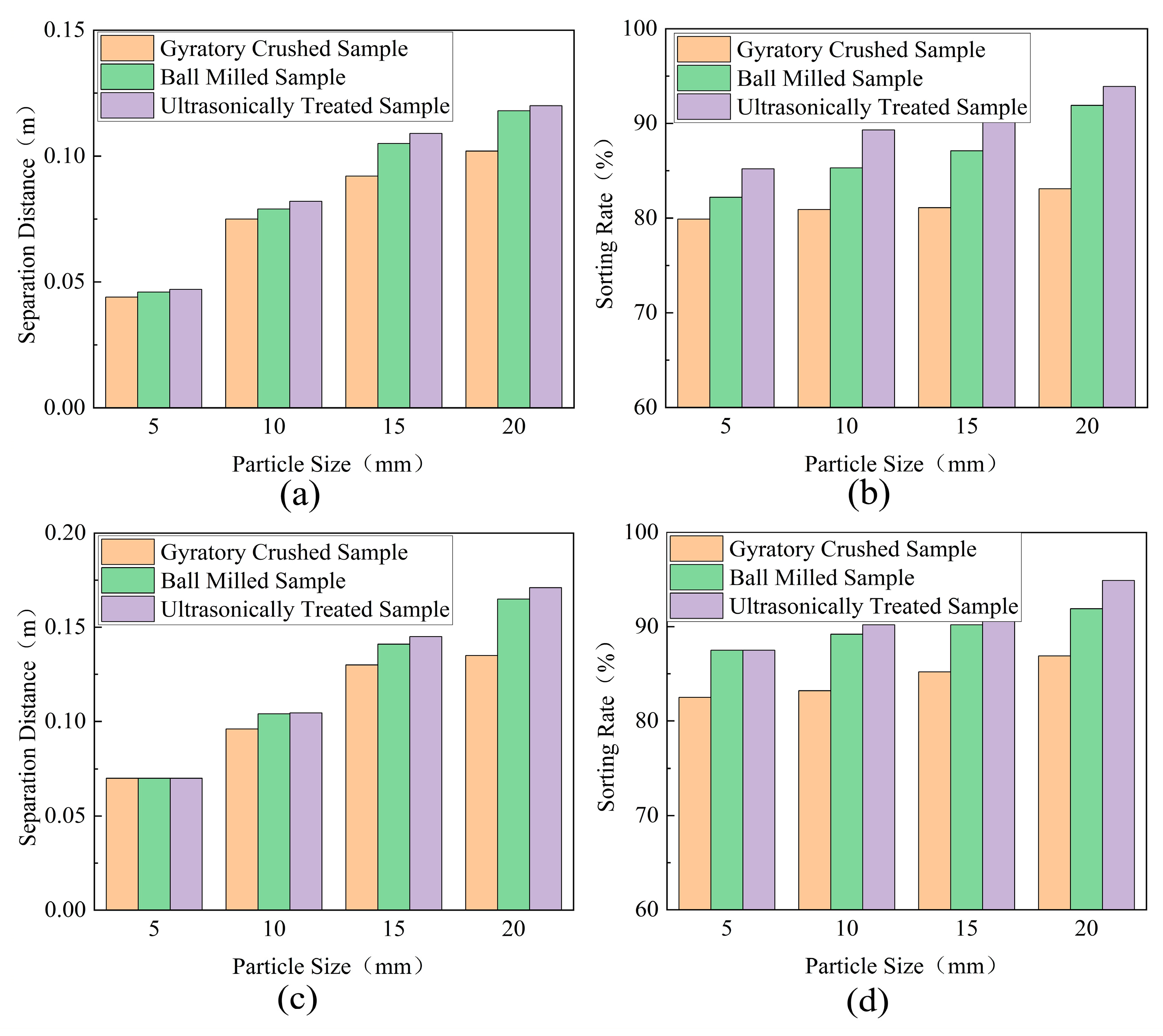
Further experiments were conducted to measure the separation distance and separation rate of samples processed via gyratory crushing, ball milling, and ultrasonic dissociation at high magnetic rotor speeds of 800 and 1000 r/min to further verify the impact of the crushing and dissociation methods on the eddy current separation efficiency of the products. The statistical results are shown in Figure 15, from which it can be seen that the different methods’ eddy current separation efficiency shows the following order: ultrasonic treatment > ball milling > gyratory crushing. The high eddy current separation efficiency of the ultrasonic treatment samples is attributed to their smooth surface properties; however, given the processing efficiency requirements in industrial recycling, ball milling may be considered more suitable for large-scale recovery processes.

3.6. Environmental Impact and Energy Consumption Analysis

A total of 300 discarded lithium iron phosphate batteries were used in the entire experimental process. After disassembly, crushing, and sorting using purely mechanical methods, the following quantities were obtained: 8.70 kg of negative current collectors, 15.68 kg of positive current collectors, 23.53 kg of positive electrode material, 14.50 kg of negative electrode material, 3.08 kg of olefin separator, and approximately 20.65 kg of battery casing, resulting in a total recovered product mass of approximately 86.14 kg. No additional chemical reagents were introduced during the material separation process, except for the salt solution used for discharge and dimethyl carbonate used for cleaning. Moreover, no by-products from high-temperature processing were generated. The equipment used in each process step and its total energy consumption are shown in Table 5. Ball milling, gyratory crushing, and ultrasonic treatment were used for dissociation of parts of the electrode sheets, while other equipment handled all the battery samples. The eddy current separation parameters were set according to the previously optimized conditions. The average recovery energy consumption for mixed materials under laboratory conditions was approximately 0.36 kWh/kg, significantly lower than the 3.3–17.1 kWh/kg reported for pyrometallurgical recycling [39]. Furthermore, due to the limitations of the equipment ratio and spatial distribution at the laboratory scale, the energy consumption of the equipment is not balanced; at an industrial scale, the equipment ratio can still be significantly optimized to further reduce energy consumption.

4. Conclusions

Based on a rotating magnetic field model excited by alternating permanent magnets, this study investigated the forces and motion trajectories of current collectors and electrode materials derived from spent lithium iron phosphate batteries in an alternating magnetic field. Comparing the theoretical and experimental results, the effects of cathode material performance degradation and magnetic field conditions on the efficiency of the eddy current separation process were analyzed. The results demonstrated that compared with pristine lithium iron phosphate material, the cathode material experiences a pronounced decline in electromagnetic load-carrying capacity after charge–discharge cycling and mechanical crushing, which is unfavorable for forming stable induced eddy currents in an alternating magnetic field. Consequently, its motion trajectory during eddy current separation is close to that of non-conductive materials, enabling effective separation from the crushed current collector products. For current collector materials, sufficiently large particle sizes and a relatively regular surface morphology are required to generate eddy currents of adequate magnitude within the particles; however, the positive effect of increasing particle size on eddy current separation efficiency exhibits a boundary (i.e., limiting) effect. Compared with conventional crushing methods, ball milling or ultrasonic treatment are ideal pretreatment processes for eddy current separation of battery materials. Under conditions of a particle size of 20 mm, a magnetic rotor speed of 1000 r/min, and a conveyor belt speed of 70 r/min, the mixed materials achieved the best eddy current separation performance, with single-pass separation rates of 90.2% for aluminum, 91.9% for copper, and 95.1% for lithium iron phosphate. In addition, this study employed fully mechanical and physical methods to separate and recover the crushed products of spent lithium iron phosphate batteries, avoiding the use of high-temperature roasting and chemical reagents and thus provides an environmentally friendly route for battery recycling.

Author Contributions

Conceptualization, H.Z.; Methodology, H.Z.; Software, Y.B. and Y.H.; Validation, H.B.; Formal analysis, Y.B.; Resources, H.Z.; Data curation, H.B.; Writing—original draft, Y.B.; Visualization, Y.H. All authors have read and agreed to the published version of the manuscript.

Funding

This research was funded by the National Natural Science Foundation of China [grant number 52205509], the Anhui Provincial Natural Science Foundation [grant number 2208085QE155], and Key Project of Natural Science Research for Universities in Anhui Province [grant number 2024AH050444].

Data Availability Statement

The original contributions presented in this study are included in the article. Further inquiries can be directed to the corresponding author.

Conflicts of Interest

The authors declare no conflict of interest.

References

  1. Tian, J.; Fan, Y.; Pan, T.; Zhang, X.; Yin, J.; Zhang, Q. A critical review on inconsistency mechanism, evaluation methods and improvement measures for lithium-ion battery energy storage systems. Renew. Sustain. Energy Rev. 2024, 189, 113978. [Google Scholar] [CrossRef] [Scilit]
  2. Liu, S.; Yan, J.; Yan, Y.; Zhang, H.; Zhang, J.; Liu, Y.; Han, S. Joint operation of mobile battery, power system, and transportation system for improving the renewable energy penetration rate. Appl. Energy 2024, 357, 122455. [Google Scholar] [CrossRef] [Scilit]
  3. Ramasubramanian, B.; Sundarrajan, S.; Chellappan, V.; Reddy, M.V.; Ramakrishna, S.; Zaghib, K. Recent development in carbon-LiFePO4 cathodes for lithium-ion batteries: A mini review. Batteries 2022, 8, 133. [Google Scholar] [CrossRef] [Scilit]
  4. Wang, M.; Liu, K.; Dutta, S.; Alessi, D.S.; Rinklebe, J.; Ok, Y.S.; Tsang, D.C. Recycling of lithium iron phosphate batteries: Status, technologies, challenges, and prospects. Renew. Sustain. Energy Rev. 2022, 163, 112515. [Google Scholar] [CrossRef] [Scilit]
  5. Cao, Y.; Xu, X.; Wen, G.; Yuan, S.; Lei, S.; Han, C.; Li, Z. Efficient recycling of spent lithium iron phosphate batteries by chlorination roasting with CaCl2. J. Environ. Chem. Eng. 2025, 13, 120230. [Google Scholar] [CrossRef] [Scilit]
  6. Quilty, C.D.; Wu, D.; Li, W.; Bock, D.C.; Wang, L.; Housel, L.M.; Abraham, A.; Takeuchi, K.J.; Marschilok, A.C.; Takeuchi, E.S. Electron and ion transport in lithium and lithium-ion battery negative and positive composite electrodes. Chem. Rev. 2023, 123, 1327–1363. [Google Scholar] [CrossRef] [Scilit]
  7. Xu, Z.; Wang, J.; Lund, P.D.; Fan, Q.; Dong, T.; Liang, Y.; Hong, J. A novel clustering algorithm for grouping and cascade utilization of retired Li-ion batteries. J. Energy Storage 2020, 29, 101303. [Google Scholar] [CrossRef] [Scilit]
  8. Hu, Z.; Yu, B.; Daigo, I.; Tan, J.; Sun, F.; Zhang, S. Circular economy strategies for mitigating metals shortages in electric vehicle batteries under China’s carbon-neutral target. J. Environ. Manag. 2024, 352, 120079. [Google Scholar] [CrossRef] [Scilit] [PubMed]
  9. Tan, Q.; Li, J.; Yang, L.; Xu, G. Cascade use potential of retired traction batteries for renewable energy storage in China under carbon peak vision. J. Clean. Prod. 2023, 412, 137379. [Google Scholar] [CrossRef] [Scilit]
  10. Yu, J.; Huang, K.; Zheng, J.; Zhang, L. Advance Technology for Treatment and Recycling of Electrolyte and Organic Matters from Spent Lithium-ion Battery. Curr. Opin. Green Sustain. Chem. 2024, 47, 100914. [Google Scholar] [CrossRef] [Scilit]
  11. Wu, X.; Ma, J.; Wang, J.; Zhang, X.; Zhou, G.; Liang, Z. Progress, Key Issues, and Future Prospects for Li-Ion Battery Recycling. Glob. Chall. 2022, 6, 2200067. [Google Scholar] [CrossRef] [Scilit]
  12. Wu, J.; Zheng, M.; Liu, T.; Wang, Y.; Liu, Y.; Nai, J.; Zhang, L.; Zhang, S.; Tao, X. Direct recovery: A sustainable recycling technology for spent lithium-ion battery. Energy Storage Mater. 2023, 54, 120–134. [Google Scholar] [CrossRef] [Scilit]
  13. Wei, N.; He, Y.; Zhang, G.; Liu, J.; Feng, Y.; Li, Z.; Zuo, W. Recycling valuable metals from spent lithium-ion batteries by an integrated in-situ thermal reduction and electrochemical leaching strategy. Sep. Purif. Technol. 2025, 384, 136319. [Google Scholar] [CrossRef] [Scilit]
  14. Ma, X.; Meng, Z.; Bellonia, M.V.; Spangenberger, J.; Harper, G.; Gratz, E.; Olivetti, E.; Arsenault, R.; Wang, Y. The evolution of lithium-ion battery recycling. Nat. Rev. Clean Technol. 2025, 1, 75–94. [Google Scholar] [CrossRef] [Scilit]
  15. Du, K.; Ang, E.H.; Wu, X.; Liu, Y. Progresses in sustainable recycling technology of spent lithium-ion batteries. Energy Environ. Mater. 2022, 5, 1012–1036. [Google Scholar] [CrossRef] [Scilit]
  16. Bin, C.; Yi, Y.; Abdelkader, A.; Kamali, A.R.; Montalvão, D.; Qiang, W.; Zhicheng, S.; Lixue, Y. Generation mechanism and empirical model of eddy current force and torque in drum-type eddy current separation. Waste Manag. 2024, 182, 299–309. [Google Scholar] [CrossRef] [Scilit]
  17. Ruan, J.; Dong, L.; Zheng, J.; Zhang, T.; Huang, M.; Xu, Z. Key factors of eddy current separation for recovering aluminum from crushed e-waste. Waste Manag. 2017, 60, 84–90. [Google Scholar] [CrossRef] [Scilit]
  18. Wen, L.; Guan, Z.; Liu, X.; Wang, L.; Wen, G.; Zhao, Y.; Pang, D.; Dou, R. Effect of Binder on Internal Resistance and Performance of Lithium Iron Phosphate Batteries. J. Electrochem. Soc. 2023, 170, 050527. [Google Scholar] [CrossRef] [Scilit]
  19. Yang, A.; Wang, Y.; Yang, F.; Wang, D.; Zi, Y.; Tsui, K.L.; Zhang, B. A comprehensive investigation of lithium-ion battery degradation performance at different discharge rates. J. Power Sources 2019, 443, 227108. [Google Scholar] [CrossRef] [Scilit]
  20. Chen, S.P.; Lv, D.; Chen, J.; Zhang, Y.H.; Shi, F.N. Review on defects and modification methods of LiFePO4 cathode material for lithium-ion batteries. Energy Fuels 2022, 36, 1232–1251. [Google Scholar] [CrossRef] [Scilit]
  21. Li, F.; Tao, R.; Tan, X.; Xu, J.; Kong, D.; Shen, L.; Mo, R.; Li, J.; Lu, Y. Graphite-embedded lithium iron phosphate for high-power-energy cathodes. Nano Lett. 2021, 21, 2572–2579. [Google Scholar] [CrossRef] [Scilit] [PubMed]
  22. Bi, H.; Zhu, H.; Zu, L.; Gao, Y.; Gao, S.; Wu, Z. Eddy current separation for recovering aluminium and lithium-iron phosphate components of spent lithium-iron phosphate batteries. Waste Manag. Res. 2019, 37, 1217–1228. [Google Scholar] [CrossRef] [Scilit] [PubMed]
  23. Bi, H.; Zhu, H.; Zu, L.; Bai, Y.; Gao, S.; Gao, Y. A new model of trajectory in eddy current separation for recovering spent lithium iron phosphate batteries. Waste Manag. 2019, 100, 1–9. [Google Scholar] [CrossRef] [Scilit] [PubMed]
  24. Huang, Z.; Zhu, J.; Wu, X.; Qiu, R.; Xu, Z.; Ruan, J. Eddy current separation can be used in separation of non-ferrous particles from crushed waste printed circuit boards. J. Clean. Prod. 2021, 312, 127755. [Google Scholar] [CrossRef] [Scilit]
  25. Bai, Y.; Zhu, H.; Zu, L.; Zhang, Y.; Bi, H. Environment-friendly, efficient process for mechanical recovery of waste lithium iron phosphate batteries. Waste Manag. Res. 2023, 41, 1549–1558. [Google Scholar] [CrossRef] [Scilit]
  26. Forte, F.; Pietrantonio, M.; Pucciarmati, S.; Puzone, M.; Fontana, D. Lithium iron phosphate batteries recycling: An assessment of current status. Crit. Rev. Environ. Sci. Technol. 2021, 51, 2232–2259. [Google Scholar] [CrossRef] [Scilit]
  27. Yadav, P.; Jie, C.J.; Tan, S.; Srinivasan, M. Recycling of cathode from spent lithium iron phosphate batteries. J. Hazard. Mater. 2020, 399, 123068. [Google Scholar] [CrossRef] [Scilit]
  28. Jujun, R.; Yiming, Q.; Zhenming, X. Environment-friendly technology for recovering nonferrous metals from e-waste: Eddy current separation. Resour. Conserv. Recycl. 2014, 87, 109–116. [Google Scholar] [CrossRef] [Scilit]
  29. Rem, P.C.; Leest, P.A.; Van den Akker, A.J. A model for eddy current separation. Int. J. Miner. Process. 1997, 49, 193–200. [Google Scholar] [CrossRef] [Scilit]
  30. Nagel, J.R. An analytic model for eddy current separation. Miner. Eng. 2018, 127, 277–285. [Google Scholar] [CrossRef] [Scilit]
  31. Bai, Y.; Zhu, H.; Zu, L.; Bi, H. Eddy current separation of broken lithium battery products in consideration of the shape factor. J. Mater. Cycles Waste Manag. 2023, 25, 2262–2275. [Google Scholar] [CrossRef] [Scilit]
  32. Salama, A.; Richard, G.; Medles, K.; Zeghloul, T.; Dascalescu, L. Distinct recovery of copper and aluminum from waste electric wires using a roll-type electrostatic separator. Waste Manag. 2018, 76, 207–216. [Google Scholar] [CrossRef] [Scilit] [PubMed]
  33. Wang, L.; Li, J.; Zhou, H.; Huang, Z.; Tao, S.; Zhai, B.; Liu, L.; Hu, L. Regeneration cathode material mixture from spent lithium iron phosphate batteries. J. Mater. Sci. Mater. Electron. 2018, 29, 9283–9290. [Google Scholar] [CrossRef] [Scilit]
  34. Chen, L.; Chen, Z.; Liu, S.; Gao, B.; Wang, J. Effects of particle size distribution on compacted density of lithium iron phosphate 18650 battery. J. Electrochem. Energy Convers. Storage 2018, 15, 041011. [Google Scholar] [CrossRef] [Scilit]
  35. Channagiri, S.A.; Nagpure, S.C.; Babu, S.S.; Noble, G.J.; Hart, R.T. Porosity and phase fraction evolution with aging in lithium iron phosphate battery cathodes. J. Power Sources 2013, 243, 750–757. [Google Scholar] [CrossRef] [Scilit]
  36. Spotte-Smith, E.W.C.; Petrocelli, T.B.; Patel, H.D.; Blau, S.M.; Persson, K.A. Elementary decomposition mechanisms of lithium hexafluorophosphate in battery electrolytes and interphases. ACS Energy Lett. 2022, 8, 347–355. [Google Scholar] [CrossRef] [Scilit]
  37. Ding, L.; Leones, R.; Schmeida, T.; Nielsch, K.; Mikhailova, D. Superior high-temperature rate performance of LiFePO4 cathode: The stabilizing effect of a multicomponent gel biopolymer binder. J. Power Sources 2022, 521, 230955. [Google Scholar] [CrossRef] [Scilit]
  38. Bi, H.; Zhu, H.; Zu, L.; Gao, Y.; Gao, S.; Bai, Y. Environment-friendly technology for recovering cathode materials from spent lithium iron phosphate batteries. Waste Manag. Res. 2020, 37, 767–780. [Google Scholar] [CrossRef] [Scilit]
  39. Hanna, F.; Somers, C.; Anctil, A. Life cycle assessment of lithium-ion battery recycling: Evaluating the impact of recycling methods and location. Environ. Sci. Technol. 2025, 59, 14432–14443. [Google Scholar] [CrossRef] [Scilit]
Figure 1. Principle of induced eddy currents in conductive materials in an alternating magnetic field.
Separations 13 00091 g001
Figure 2. Flowchart of the eddy current sorting experiment for lithium-ion batteries.
Separations 13 00091 g002
Figure 3. (a) Cross-sectional view of the magnetic field distribution on the surface of a static magnetic rotor. (b) Cross-sectional view of the dynamic magnetic field distribution on the surface of a rotating magnetic rotor. (c) Distribution pattern of the magnetic field strength at the junction of the magnetic rotor’s magnetic poles. (d) Distribution pattern of the magnetic field strength in the direction of the N magnetic pole of the magnetic rotor.
Separations 13 00091 g003
Figure 4. Magnetic field distribution pattern in the axial vertical cross-section of an alternating permanent magnet in a rotating state.
Separations 13 00091 g004
Figure 5. Magnetic field distribution pattern in the axial end-face of an alternating permanent magnet in a rotating state.
Separations 13 00091 g005
Figure 6. SEM-EDS characterization results for lithium iron phosphate battery cathode production waste.
Separations 13 00091 g006
Figure 7. SEM-EDS characterization results for waste lithium iron phosphate battery cathode sheets.
Separations 13 00091 g007
Figure 8. Relationships between compaction density and resistivity for various lithium iron phosphate powders with respect to surface pressure: (a,b) Cathode coating production waste, (c,d) high-purity lithium iron phosphate powder, and (e,f) crushed powder from the cathode coating of waste batteries.
Separations 13 00091 g008
Figure 9. Simulation results of detachment angles for 2 and 5 mm particle size current collector materials in an alternating magnetic field.
Separations 13 00091 g009
Figure 10. Simulation results of detachment angles for 10 and 15 mm particle size current collector materials in an alternating magnetic field.
Separations 13 00091 g010
Figure 11. Simulation results of detachment angles for 20 and 25 mm particle size current collector materials in an alternating magnetic field.
Separations 13 00091 g011
Figure 12. Motion trajectories of aluminum, copper, and lithium iron phosphate particles in an alternating magnetic field under particle size conditions of (a) 2, (b) 5, (c) 10, and (d) 20 mm.
Separations 13 00091 g012
Figure 13. Motion trajectories of aluminum, copper, and lithium iron phosphate particles in an alternating magnetic field under the particle size condition of 20 mm at magnetic rotor speeds of (a) 400, (b) 600, (c) 800, and (d) 1000 r/min.
Separations 13 00091 g013
Figure 14. Effects of magnetic rotor speed and particle size on (a,c) separation distance and (b,d) separation rate at conveyor belt speeds of 55 r/min (a,b) and 70 r/min (c,d) (Colors indicate the magnitude of separation, and black dots show the experimental data points).
Separations 13 00091 g014
Figure 15. Effects of different pretreatment methods on (a,c) separation distance and (b,d) separation rate of lithium iron phosphate battery crushed products at magnetic rotor speeds of 800 r/min (a,b) and 1000 r/min (c,d).
Separations 13 00091 g015
Table 1. Eddy current separation experiment results for crushed lithium iron phosphate battery products with a particle size of 2 mm.
Magnetic Rotor Speed (r/min)Separation Distance/mSeparation Rate (%)
Feed Speed (55 r/min)Feed Speed
(60 r/min)
Feed Speed
(65 r/min)
Feed Speed
(70 r/min)
4000.0090.0100.0100.00958.7
6000.0150.0150.0150.01566.9
8000.0210.0210.0220.02269.2
10000.0250.0250.0250.02673.4
Table 2. Eddy current separation experiment results for crushed lithium iron phosphate battery products with a particle size of 5 mm.
Magnetic Rotor Speed (r/min)Separation Distance/mSeparation Rate (%)
Feed Speed (55 r/min)Feed Speed
(60 r/min)
Feed Speed
(65 r/min)
Feed Speed
(70 r/min)
4000.0200.0200.0200.02077.6
6000.0340.0340.0330.03381.5
8000.0430.0440.0460.04682.2
10000.0680.0680.0700.07087.5
Table 3. Eddy current separation experiment results for crushed lithium iron phosphate battery products with a particle size of 10 mm.
Magnetic Rotor Speed (r/min)Separation Distance/mSeparation Rate (%)
Feed Speed (55 r/min)Feed Speed
(60 r/min)
Feed Speed
(65 r/min)
Feed Speed
(70 r/min)
4000.0360.0390.0400.04481.3
6000.0420.0440.0460.04986.2
8000.0670.0690.0730.07987.5
10000.0970.0970.0990.10490.3
Table 4. Eddy current separation experiment results for crushed lithium iron phosphate battery products with a particle size of 20 mm.
Magnetic Rotor Speed (r/min)Separation Distance/mSeparation Rate (%)
Feed Speed (55 r/min)Feed Speed
(60 r/min)
Feed Speed
(65 r/min)
Feed Speed
(70 r/min)
4000.0780.0800.0800.08081.5
6000.0940.0990.1030.10588.7
8000.1120.1170.1180.11889.3
10000.1600.1610.1630.16492.0
Table 5. Energy consumption of each separate process in the recovery of lithium iron phosphate batteries.
Process StageEquipmentPower (kW)Energy Consumption (kW·h)
DisassemblyCNC milling machine52.93
Integrated disassembly unit1.75.35
Fume hood0.21.81
DissociationBall mill1.53.45
Crusher23.13
Ultrasonic unit1.26.33
SortingEddy current separator4.55.45
ScreeningRotary vibrating screen0.52.18
Disclaimer/Publisher’s Note: The statements, opinions and data contained in all publications are solely those of the individual author(s) and contributor(s) and not of MDPI and/or the editor(s). MDPI and/or the editor(s) disclaim responsibility for any injury to people or property resulting from any ideas, methods, instructions or products referred to in the content.