Article

CFD-DEM Simulation of the Effect of Transverse Inclination Angle on Particle Moving Behavior in Spiral Separation

1
China ENFI Engineering Corporation, Beijing 100038, China
2
College of Mining Engineering, Taiyuan University of Technology, Taiyuan 030024, China
3
Langfang North Tianyu Electromechanical Technology Co., Ltd., Langfang 065000, China
*
Author to whom correspondence should be addressed.
Separations 2026, 13(2), 73; https://doi.org/10.3390/separations13020073
Submission received: 21 January 2026 / Revised: 12 February 2026 / Accepted: 14 February 2026 / Published: 19 February 2026
(This article belongs to the Special Issue Separation Technology in Mineral Processing)

Abstract

Spiral separators commonly face the issue of particle misplacement during fine particle separation, which severely limits separation accuracy. This study employs a coupled CFD-DEM numerical simulation method to systematically investigate the influence mechanism of transverse inclination angle (10°, 15°, 20°) on particle moving behavior. The results show that the separation process exhibits distinct stage characteristics, which can be divided into an initial stage (first 1/3 turn), a transition stage (1/3 to 2 turns), and a quasi-steady stage (after 2 turns). A steeper angle (20°) optimizes the flow field, reducing the inner low-velocity zone and widening the high-velocity core, which promotes inward migration of particles. This enhances the enrichment of high-density particles while effectively suppressing their mixing into the clean coal product at the outer edge. For difficult-to-separate fine particles below 0.1 mm, although complete separation is challenging, increasing the transverse inclination angle still shows a clear reduction in the misplacement of high-density particles, providing a controllable approach for improving the quality of the outer edge product. This study offers theoretical insights and design guidance for optimizing spiral separator structures and enhancing fine coal separation efficiency.

1. Introduction

Spiral separators, as gravity-based concentration equipment, are recognized for their low energy consumption, simple structure, high processing capacity, and chemical-free operation. They have emerged as a core technology not only for clean and efficient fine coal processing [1,2,3], but also for the recovery of resources from a variety of materials, including iron ore, coastal placer deposits, and solid wastes [4,5,6,7]. Consequently, a deeper understanding of the underlying separation mechanisms within spiral separators is crucial to enhance process efficiency and achieve high-precision beneficiation of complex resources.
Extensive research on the hydrodynamic characteristics within the spiral trough has been motivated by the need for a deeper mechanistic understanding. Early foundational work by Doheim [8], Matthews [9], and later studies by Reddy [10], Meng [11], Ye [12], employing both experimental and numerical methods, have successfully established a consensus on the fundamental flow patterns. These studies consistently show that the fluid film thickness increases gradually from the inner to the outer edge of the trough, with especially pronounced thickening in the outermost region. Correspondingly, the axial velocity of the flow follows a similar radial trend, rising from a minimum at the inner edge to a maximum at the outer edge, where the velocity increases markedly. Furthermore, the flow regime transitions radially: the inner zone is characterized by stable laminar flow, which gives way to a transitional flow in the intermediate zone, and finally evolves into fully developed turbulence in the outer zone, where the intensity of turbulence is significantly intensified. Building on this descriptive foundation, subsequent research has progressively shifted towards a more causative analysis, focusing on how specific structural parameters dictate these flow conditions. For instance, the work of Ye [12,13] and Meng [14] demonstrated that parameters such as the pitch and trough geometry exert a significant influence on the velocity and thickness distribution, particularly in the outer region during the initial stages of operation. This research focus has evolved from flow characterization to explaining how the separator’s design shapes it. This shift highlights a critical principle: hydrodynamic performance is fundamentally governed by geometry.
Following the establishment of flow field characteristics, research efforts have logically progressed to deciphering particle motion behavior, which is the direct determinant of separation efficiency. Initial insights were gained primarily through conventional separation experiments. For instance, Atasoy et al. [15] and Li et al. [16] observed the distribution of middling-density particles across both the outer and inner regions of the trough, providing direct evidence that particle misplacement is a primary factor limiting separation efficiency. To overcome the limitations of macroscopic experiments and capture the intricacies of particle trajectories, advanced tracer techniques such as Positron Emission Particle Tracking (PEPT) were introduced. Studies by Boucher et al. [17,18,19] utilizing PEPT successfully revealed the fundamental separation process of particles by density, offering unprecedented insights into individual particle motion. However, the high cost and scarcity of PEPT equipment have constrained its application in studying complex multi-particle systems. Concurrently, numerical simulation has emerged as a powerful and cost-effective tool for investigating the spiral separation process. Early Eulerian two-phase (solid–liquid) flow models treated particles as a pseudo-fluid [8,20], capable of macroscopically describing particle distribution but failing to capture authentic particle-particle interactions and collision behaviors. A significant advancement was marked by the introduction of the Discrete Element Method (DEM), which enabled precise simulation of dilute particle flow by resolving individual particle contacts [13,21]. Nevertheless, the computational intensity of DEM traditionally limited its applicability under high-concentration conditions. Subsequent innovations, including the Smoothed Particle Hydrodynamics (SPH) method [22] and multiphase CFD models like the Algebraic Slip Mixture model [23] and the Eulerian multi-fluid VOF model incorporating the Bagnold force [24], have progressively enhanced the capability to simulate particle transport patterns across varying solid concentrations and accurately predict both the flow film interface and particle separation behavior. This evolution in numerical approaches has opened new pathways for elucidating the underlying mechanisms of particle misplacement.
While the aforementioned studies have significantly advanced our understanding of the spiral separation process, a conspicuous gap remains when viewed through the lens of the governing ‘geometry-dictates-performance’ principle. Most previous investigations, including those by Meng et al. [11], Gao et al. [25], and Ye [12], have primarily concentrated on analyzing separation performance under a fixed set of structural parameters or have been largely confined to examining the flow field characteristics within the initial two spiral turns. For instance, taking the critical transverse inclination angle as an example, prior studies [11,12,25] have investigated its effects on flow fields and particle distribution. However, their work primarily focused on steady-state conditions or the initial two spiral turns, neglecting the dynamic evolution across the entire separation process. Empirical evidence from extensive experimental studies [26] confirms that spiral separation is indeed a dynamically evolving process, wherein the separation conditions and particle trajectories undergo significant changes across different turns. This dynamic nature underscores the necessity of investigating how the transverse inclination angle affects particle behavior throughout the complete separation process, rather than focusing solely on isolated segments. The current lack of understanding in this regard substantially hinders further in-depth exploration of the fundamental principles governing coarse coal slime separation in spiral concentrators. This knowledge gap acquires particular significance in practical applications: although spiral separators are typically recommended for treating coarse coal slime in the 1.5–0.25 mm size range (e.g., from classifier cyclone underflows), industrial feed conditions frequently contain a substantial fraction of fine particles below 0.1 mm. These fine particles are particularly challenging to separate due to the dominance of fluid drag over gravity, leading to misplacement that compromises product quality. Therefore, systematic clarification of how the transverse inclination angle affects the behavior of these difficult-to-separate fine particles throughout the entire separation process is essential for optimizing separator design.
To address this gap, the present study employs a coupled Computational Fluid Dynamics-Discrete Element Method (CFD-DEM) numerical simulation approach to systematically investigate the underlying mechanisms. This study aims to: (1) elucidate the fluid distribution and particle transport behavior within the spiral trough under varying transverse inclination angles (10°, 15°, and 20°); and (2) quantitatively analyze how this key parameter influences the misplacement behavior of fine particles (0.1 mm). The findings demonstrate that adjusting the transverse inclination angle effectively modulates the flow field, which in turn governs particle separation and migration trajectories. This work provides novel insights into the dynamic separation process and offers a theoretical basis for optimizing the structure of spiral separators to enhance the efficient cleaning of fine coal.

2. Experimental and Computational Approach

2.1. Materials and Experimental Set-Up

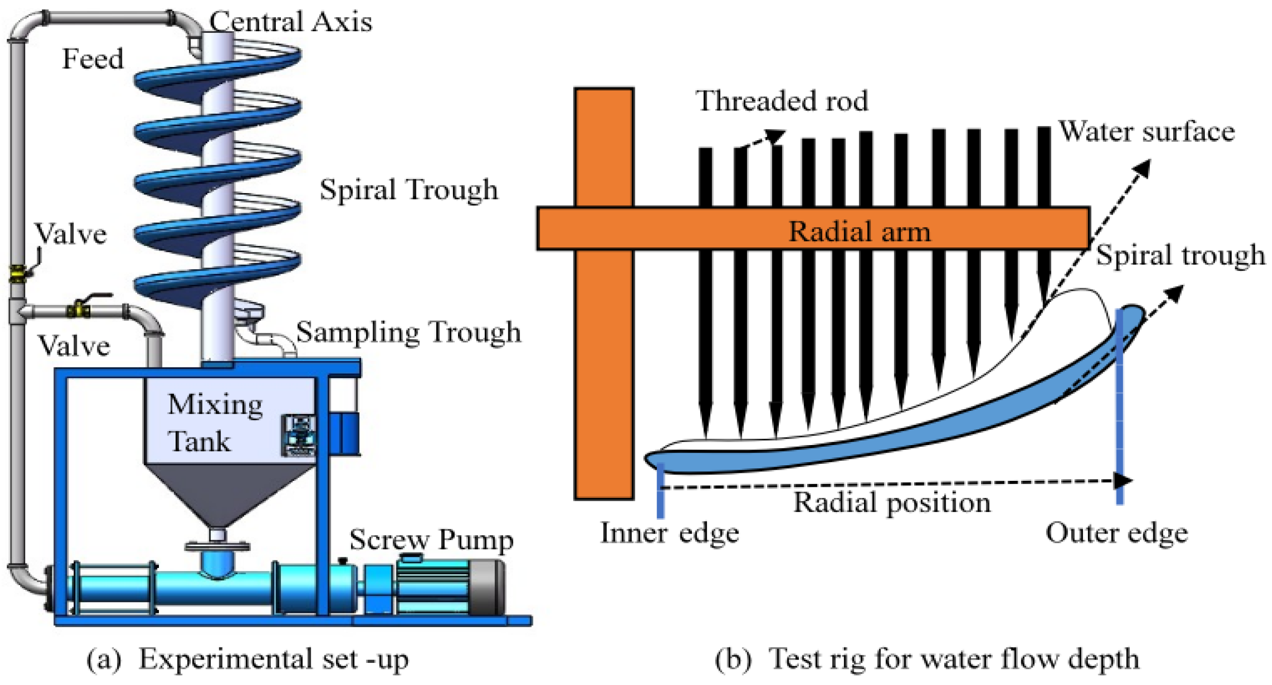
The laboratory experiments were conducted using a five-turn spiral separator operating in a closed-circuit system. The key geometric parameters of the separator were as follows: a trough diameter of 400 mm, a pitch of 160 mm, and an overall height of 800 mm. The trough profile was designed based on a composite curve comprising a cubic parabola and an ellipse. For the tracer experiments, the transverse inclination angle was fixed at 15°. Green glass microspheres (density: 2.45 g/cm3) with a particle size fraction of −0.25 mm were utilized as tracer particles to track and analyze their motion trajectories within the flow field. A schematic diagram of the experimental setup and the water flow depth measurement rig [27] is presented in Figure 1.

2.2. Geometry and Computation of the Grid

To systematically investigate the influence of the transverse inclination angle on the separation process, three-dimensional models of the spiral separator were developed with transverse inclination angles of 10°, 15°, and 20°. All other structural parameters of these models were consistent with the experimental device described in Section 2.1. Given the critical role of the thin fluid film and the significant influence of the bottom boundary layer, accurately resolving the near-wall flow field is critical for simulating the spiral separation process. Therefore, local mesh refinement was applied to the near-wall region during grid generation.
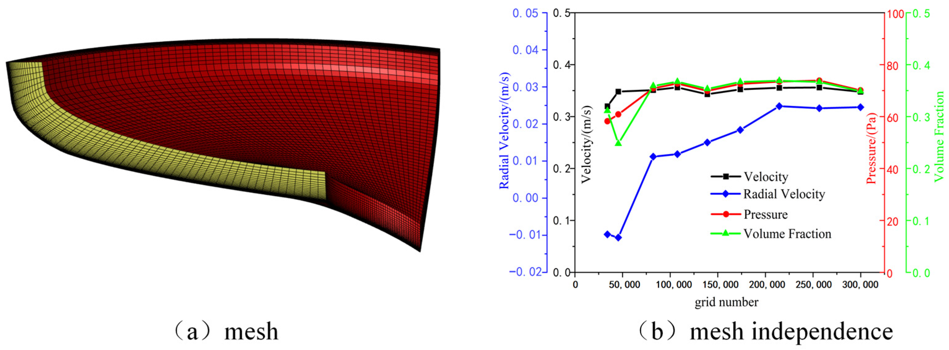
This strategy ensured a dimensionless wall distance (y+) of less than 5, thereby satisfying the resolution requirements for the near-wall treatment prescribed by the selected turbulence model in accordance with the ANSYS Fluent 19.2 Theory Guide [28]. Leveraging the periodic nature of the spiral trough geometry, a 0.25-turn section was selected as the computational domain for mesh independence verification. The spiral trough was discretized using hexahedral structured grids generated with ICEM CFD 19.2, with refinement applied to the near-wall region, as illustrated in Figure 2a. The mesh independence study, presented in Figure 2b, demonstrated that key parameters, including the outlet total pressure, velocity, volume fraction, and radial velocity, achieved convergence when the number of grid cells reached 214,650. Following this validation, the total number of grid cells for the complete five-turn spiral model was determined to be 4,293,000.

2.3. Numerical Treatment

The Volume of Fluid (VOF) multiphase model was employed to accurately capture the gas–liquid interface within the computational domain, thereby simulating the characteristics of the air-water flow field in the spiral separator [29]. To accurately resolve the turbulent flow inherent to high-velocity swirling motion, the RNG k-ε model was selected as the turbulence closure. A velocity inlet boundary condition was applied at the spiral trough entrance, with a volumetric flow rate set at 0.8 m3/h. The inlet velocity was calculated as the ratio of this volumetric flow rate to the inlet cross-sectional area. The outlet was set to a pressure outlet condition. The governing equations for the multiphase flow simulation, along with other specific model parameters, are consistent with those well-established in previous studies [12,14,23].
The motion of particles was simulated using the commercial Discrete Element Method (DEM) software, EDEM 2020 (DEM Solutions Ltd., Edinburgh, UK). Given the focus on a dilute particle flow regime, a one-way coupled CFD-DEM numerical scheme was implemented. This approach is justified primarily by the low global solid concentration, which ensures a dilute particle flow regime. In such regimes, the momentum transfer from the discrete particles back to the continuum fluid phase is negligible compared to the dominant hydrodynamic forces governing the fluid flow itself. This simplification has been successfully employed in fundamental studies of particle-laden flows, enabling efficient resolution of individual particle trajectories in centrifugal separators and spiral concentrators [13,30].
The particles were modeled as discrete spheres with densities of 1.25, 1.65, and 2.45 g/cm3, representing low-, middling-, and high-density categories, respectively. The particle size followed a random distribution within the range of 0 to 1.5 mm. All particles were introduced at the inlet with an initial velocity of 0.322 m/s at a generation rate of 600 particles per second. The gravitational acceleration was set to 9.81 m/s2. A summary of all key parameters used in the CFD-DEM simulations is provided in Table 1 to ensure clarity and reproducibility.
Within the CFD-DEM formulation, the trajectory and rotation of each particle are determined by integrating Newton’s second law. The governing equations for a particle i at time t are given by:
m i d V i d t = f p f , i + m i g + j = 1 k i ( f c , i j + f d , i j )
I i d w i d t = j = 1 k i ( T t , i j + T r , i j )
where
f p f , i represents the particle–fluid interaction force acting on particle i (N). This includes the fluid drag force F d , the added mass force F A , the pressure gradient force F p , the Magnus lift force F M , the Saffman lift force F S , and the Basset force F B .
m i g denotes the gravitational force on particle i (N).
f c , i j is the contact force between particle i and particle j (N).
f d , i j represents the non-contact force between particle i and particle j (N).
T t , i j and T r , i j are the moments acting on particle i due to translation and rotation, respectively (N·m).
The feedback effect of particles on the fluid flow field is neglected in this study, as their relatively small mass and the dilute flow regime render this influence negligible. Consequently, the added mass force is omitted from the model [21,23,24]. Furthermore, following the analysis of Sun et al. for coarse slime separation [31], a comparison of force magnitudes indicates that under the specific flow conditions in a spiral separator, the Saffman and Magnus lift forces are negligible compared to the dominant fluid drag force. Therefore, these lift forces are also disregarded. Calculating the fluid forces acting on particles within the EDEM software is crucial for the field-coupling simulation of CFD-DEM. In the discrete element simulation of particles, the fluid drag force on a single particle is given by [32]:
F d = C f 1 2 ρ l ( | u p u | ( u p u ) ) π D 2 4 ζ
The fluid drag force formula for a particle swarm is further modified as:
F d = 3 4 ρ l ε p ( | u p u | ( u p u ) ) D C f ζ
where ε p is the solid volume fraction; ζ is the fluid drag coefficient (dependent on the Reynolds number); u p is the particle velocity (m/s); u is the fluid velocity (m/s); D is the particle diameter (m); C f is functions related to the fluid volume fraction ε f . ε f can be expressed as:
ε f = 1 j = 1 K c V i V c
where V i represents the volume of the i-th particle (m3); V c is the total volume of the control volume (m3); K c is the total number of particles within the control volume.
It should be noted that the flow field in the spiral trough exhibits a complex distribution, which can be sequentially divided from the inner to the outer region into a laminar flow zone, a transitional zone, and a weakly turbulent zone [12]. Therefore, to realistically capture the particle trajectories across these distinct flow regimes, the drag coefficient in the volumetric force calculation is dynamically adjusted based on the local particle Reynolds number, as defined by Equation (6):
ζ = { 24 r e ,    r e 0.5 ( 4.8 r e + 0.63 ) 2 × ε f ( 3.7 0.65 e ( 1.5 l o g 10 r e 2 ) 2 ) ,    0.5 r e 1000 0.63 + 4.8 r e 0.5 ε f 4.14 0.06 r e + ( 0.06 r e ) 2 + 0.12 r e ( 2 ε f 2.65 ε f 4.14 ) + ( ε f 4.14 ) 2 ,    r e 1000
The governing equations for the CFD-DEM coupling are summarized in Table 2. In the above equations, E is the elastic modulus (Pa); u p is the velocity vector of the particle (m/s); R i is the radius vector of particle i (from the particle center to the contact point, m); δ n is the overlap vector between particles or between a particle and a wall in the normal direction (m); n denotes the normal direction; u n , i j is the relative velocity of particle i and particle j in the normal direction (m/s); μ p is the sliding friction coefficient of the particle; μ s is the rolling friction coefficient; δ t is the overlap vector between particles or between a particle and a wall in the tangential direction (m); C t is the damping coefficient in the tangential direction; C n is the damping coefficient in the normal direction; u t , i j is the relative velocity of particle i and particle j in the tangential direction (m/s); ω ^ i is the angular velocity (rad/s); ε is an empirical coefficient (dimensionless); P is the pressure gradient.

2.4. Particle Physical Property Calibration

The accurate calibration of particle contact parameters is critical for ensuring the fidelity of numerical simulations of fine coal particle behavior in spiral separation. While discrete element parameters for coarse particles have been calibrated experimentally in previous studies [33,34,35], the direct measurement of the coefficients of restitution, static friction, and rolling friction for fine particles is notoriously challenging. Their small size makes experimental operations cumbersome and introduces significant measurement errors. To overcome these limitations, the present study employs a systematic optimization approach, integrating the Response Surface Methodology (RSM) with particle pile formation experiments to reliably determine the optimal set of particle contact parameters.
This methodology uses the macroscopically measurable angle of repose as the response variable, with the inter-particle static friction coefficient, rolling friction coefficient, and coefficient of restitution as the influencing factors. A functional relationship is established between these discrete element parameters and the angle of repose via the RSM approach, enabling the inverse determination of the optimal parameter set that yields a simulated angle of repose matching the experimental value. The specific calibration procedure, illustrated in Figure 3, consisted of three key steps:
  • The angle of repose for the fine coal powder was first experimentally measured using the system depicted in Figure 3.
  • Based on the Generic EDEM Material Model Database, reasonable value ranges for each influencing factor were defined.
  • A numerical experimental design was formulated using RSM to construct an accurate mapping between the DEM parameters and the angle of repose, thereby identifying the optimal parameter combination that minimizes the discrepancy between simulation and physical experiment.
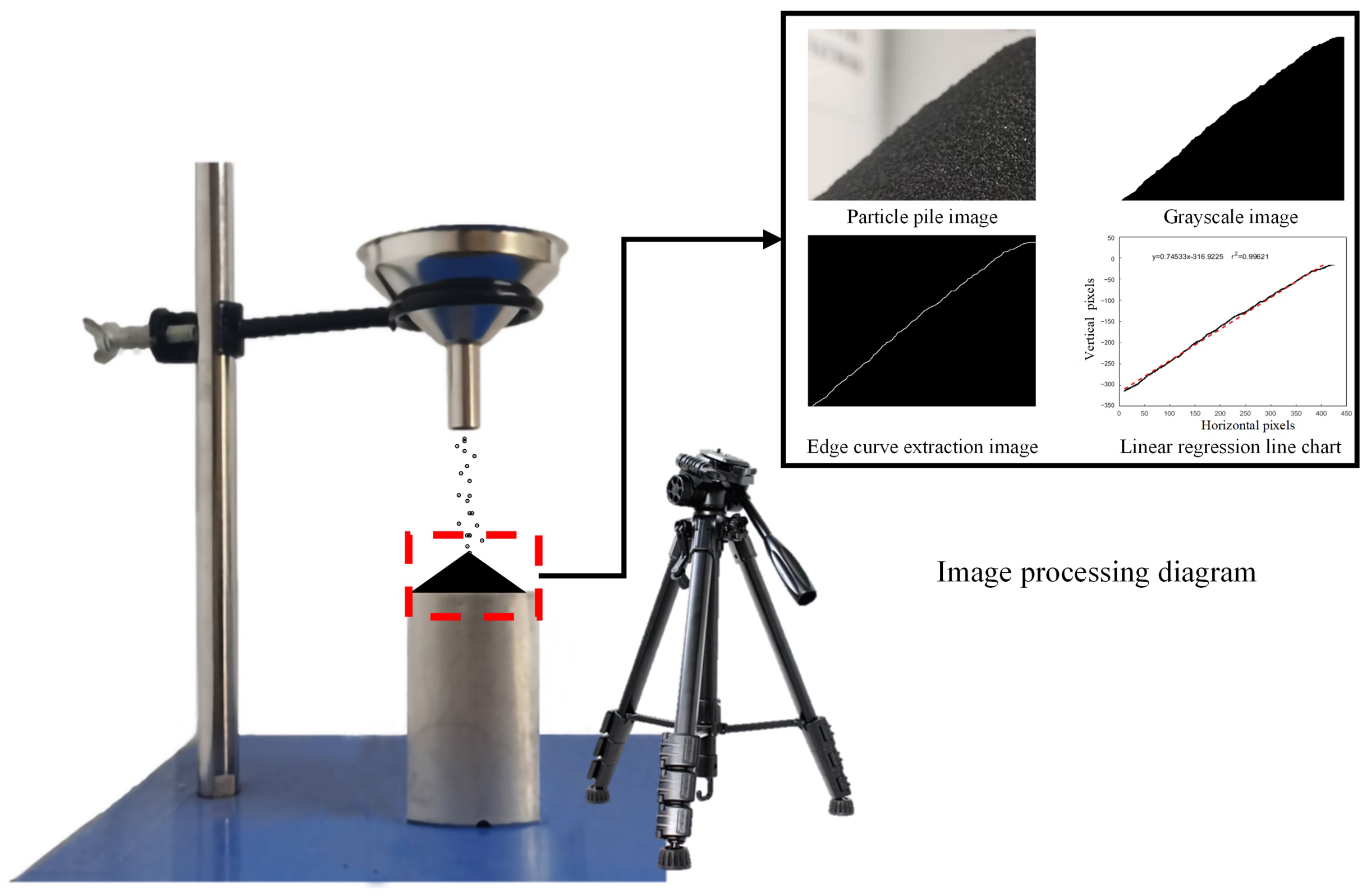
Figure 3. Schematic of the method for determining the angle of repose.
Separations 13 00073 g003
The final set of calibrated particle contact parameters adopted in this study is summarized in Table 3.

3. Results and Discussion

3.1. Model Validation and Analysis of Fluid and Particle Dynamics

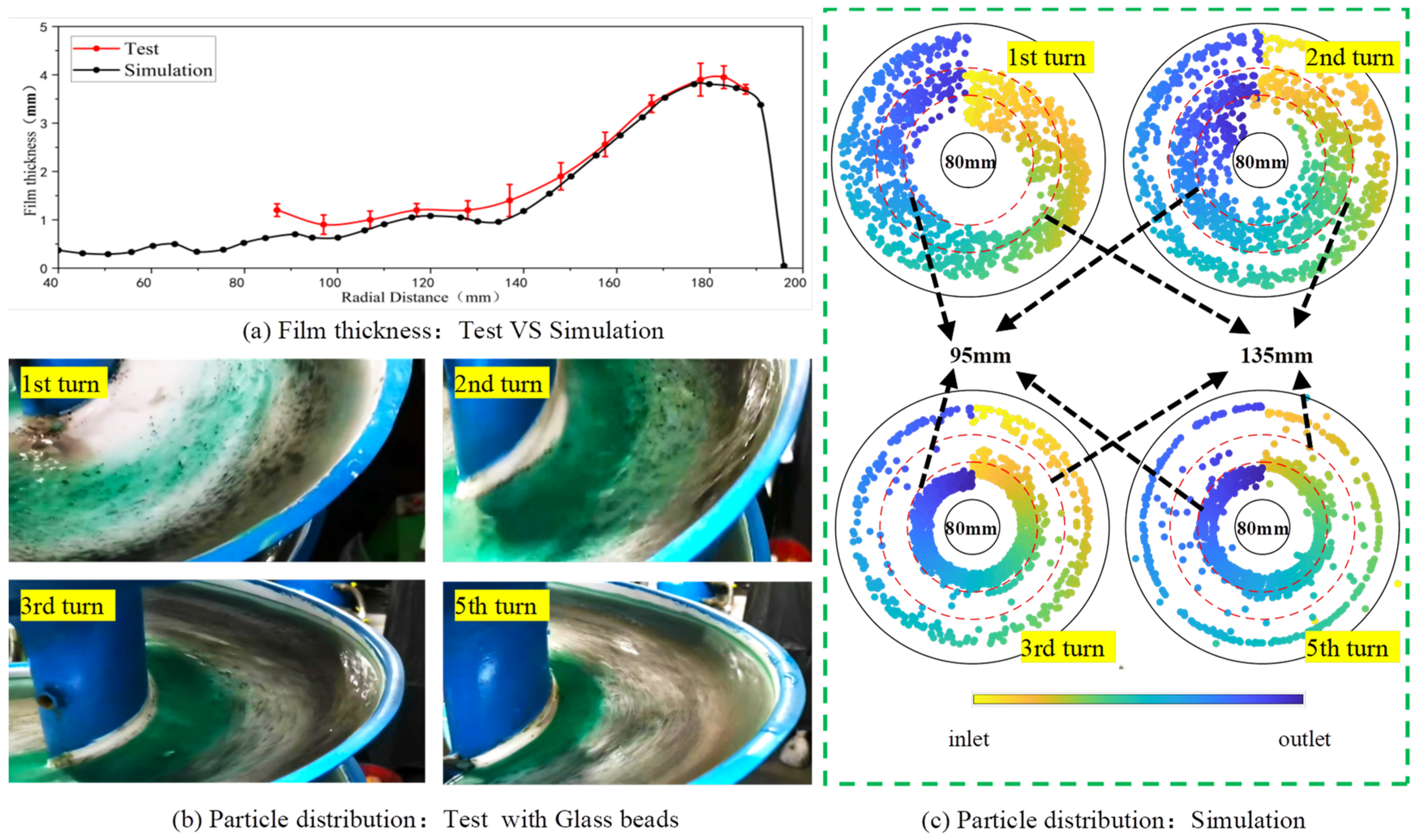
To validate the accuracy of the established CFD-DEM coupled numerical model, a comparative analysis of the flow field and particle motion was performed. Figure 4a compares the simulated and experimentally measured radial distribution of the fluid film thickness at the spiral separator outlet under a volumetric flow rate of 0.8 m3/h and a solid mass concentration of 1%. The results indicate that the simulated film thickness agrees closely with the experimental data in both the middle and outer regions of the spiral trough, confirming that the adopted flow simulation methodology accurately captures the hydrodynamic characteristics within the spiral separator.
Figure 4b,c further compares the simulated and experimental trajectories of −0.25 mm green glass microspheres (2.45 g/cm3) within the spiral trough under identical operational conditions. In the figure, particle color represents axial position, transitioning from yellow at the inlet to blue at the outlet. The simulated trajectories reveal a distinct migration pattern: during the initial turn, tracer particles are predominantly distributed in the central region of the trough. From the second turn onward, a marked inward migration toward the inner edge is observed. This enrichment process continues, resulting in the high-density particles being primarily concentrated along the inner edge by the third to fifth turns, albeit with a minor fraction remaining in the outermost region. The close agreement between the simulated and experimental distribution patterns confirms that the adopted CFD-DEM scheme effectively captures the key mechanisms of particle migration in spiral separation, thereby validating its application for subsequent detailed analysis.
It is important to note that the experimental validation presented herein was performed specifically for a transverse inclination angle of 15°. Therefore, while the model demonstrates its capability to replicate key mechanisms under this condition, the simulation results for the 10° and 20° configurations presented in the following sections should be interpreted as predictions derived from the same validated numerical framework under varied geometric input.
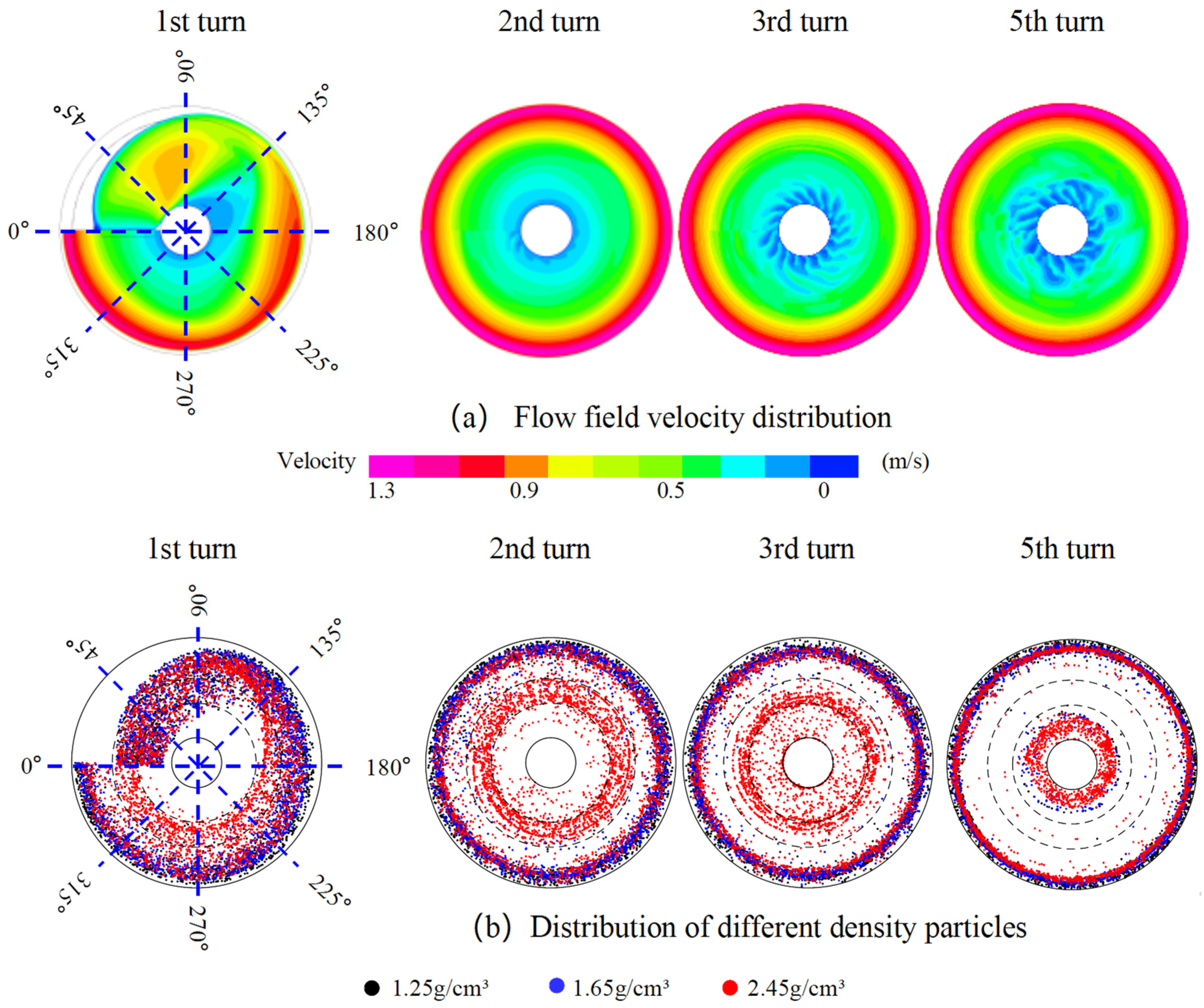
The evolution of the flow field velocity distribution throughout the spiral separation process is illustrated in Figure 5a. As can be seen, the water flow exhibits a rapid lateral expansion towards the outer edge. A critical flow restructuring occurs at approximately 120° of angular displacement, where the primary flow direction shifts abruptly and aligns with the spiral trajectory. This redirection is attributed to the collision of the incoming flow with the outer wall of the trough, as inferred from the velocity vectors and the trough geometry. Following this impact, the main fluid body develops a stable spiral trajectory. The velocity increases radially from the inner to the outer region, driven by centrifugal forces, and reaches a maximum of approximately 1.3 m/s in the outer zone—significantly exceeding the velocities in the inner and middle regions. A key observation is that the global velocity distribution stabilizes after the first turn, indicating the establishment of a developed flow. However, a more detailed examination reveals that velocity fluctuations near the inner edge, close to the central axis, become progressively more pronounced with increasing turn number.
Figure 5b illustrates the distribution of fine coal particles on the spiral trough surface, where black, blue, and red particles represent low-density (1.25 g/cm3), middling-density (1.65 g/cm3), and high-density (2.45 g/cm3) particles, respectively. The simulation results reveal a distinct separation pattern that stabilizes after the first two turns: high-density particles become concentrated along the inner edge, while middling- and low-density particles distribute toward the outer region. In terms of dynamic separation behavior, high-density particles begin to separate from the lighter fractions at approximately 120° of angular displacement, migrating inward and progressively enriching along the inner edge as the process continues. Middling- and low-density particles, meanwhile, gradually accumulate toward the outer region after the first turn. This temporal evolution exhibits clear stage-wise characteristics, with the most pronounced changes occurring during the first turn, followed by continued adjustment in the second turn, after which the distribution reaches a quasi-steady state. Based on these observations, the separation process can be divided into three distinct stages: the initial stage (first 1/3 turn), the transitional stage (1/3 to 2 turns), and the quasi-steady stage (after 2 turns).
Notably, while a clear band separation exists between high-density particles and the middling/low-density fractions, the segregation between middling- and low-density particles is less distinct, although middling-density particles are located slightly inward relative to the low-density particles. Importantly, the presence of high-density particles in the outermost region alongside the lighter particles indicates misplacement behavior, with high-density material contaminating the low-density product stream.

3.2. Response of Fluid Motion to Transverse Inclination Angle

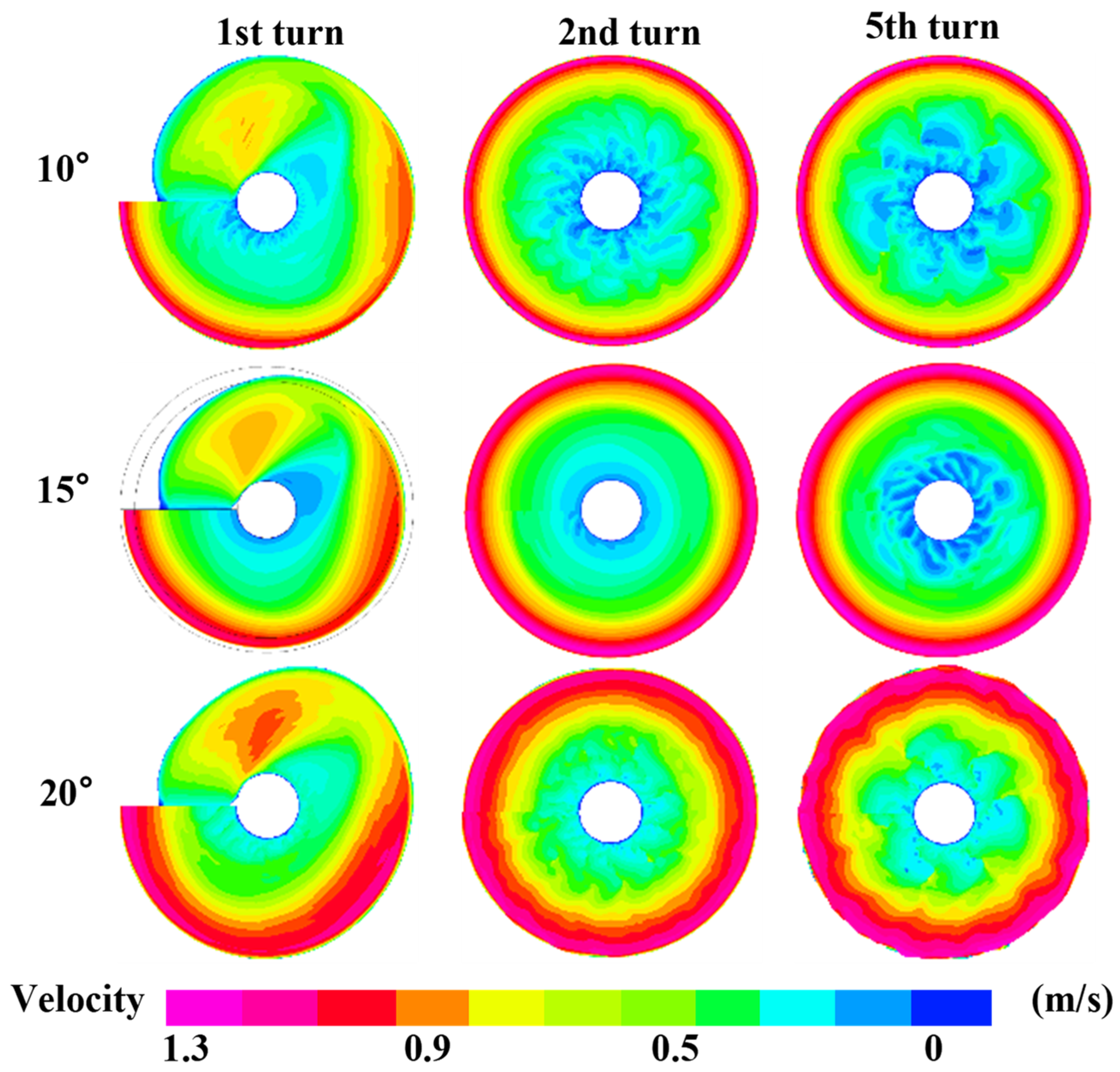
A comparative analysis of the flow field velocity distribution under different transverse inclination angles (10°, 15°, and 20°) across multiple turns is presented in Figure 6. Although the overall flow pattern—characterized by a primary current expanding toward the outer edge—remains consistent across all inclination angles, a systematic influence on the velocity distribution is evident. The maximum velocity at the outer edge shows a discernible decreasing trend as the inclination increases, from approximately 1.3 m/s at 10° and 15° to about 1.2 m/s at 20°. Concurrently, the low-velocity zone near the inner edge diminishes progressively with increasing inclination, accompanied by a significant reduction in flow fluctuations. Notably, under the 20° condition, the near-stagnant zone adjacent to the inner edge is virtually eliminated, indicating enhanced flow stability. Furthermore, the width of the high-velocity core gradually expands with a steeper inclination, suggesting that a larger transverse inclination angle promotes a wider and more uniform main flow zone.

3.3. Response of Particle Motion to Transverse Inclination Angle

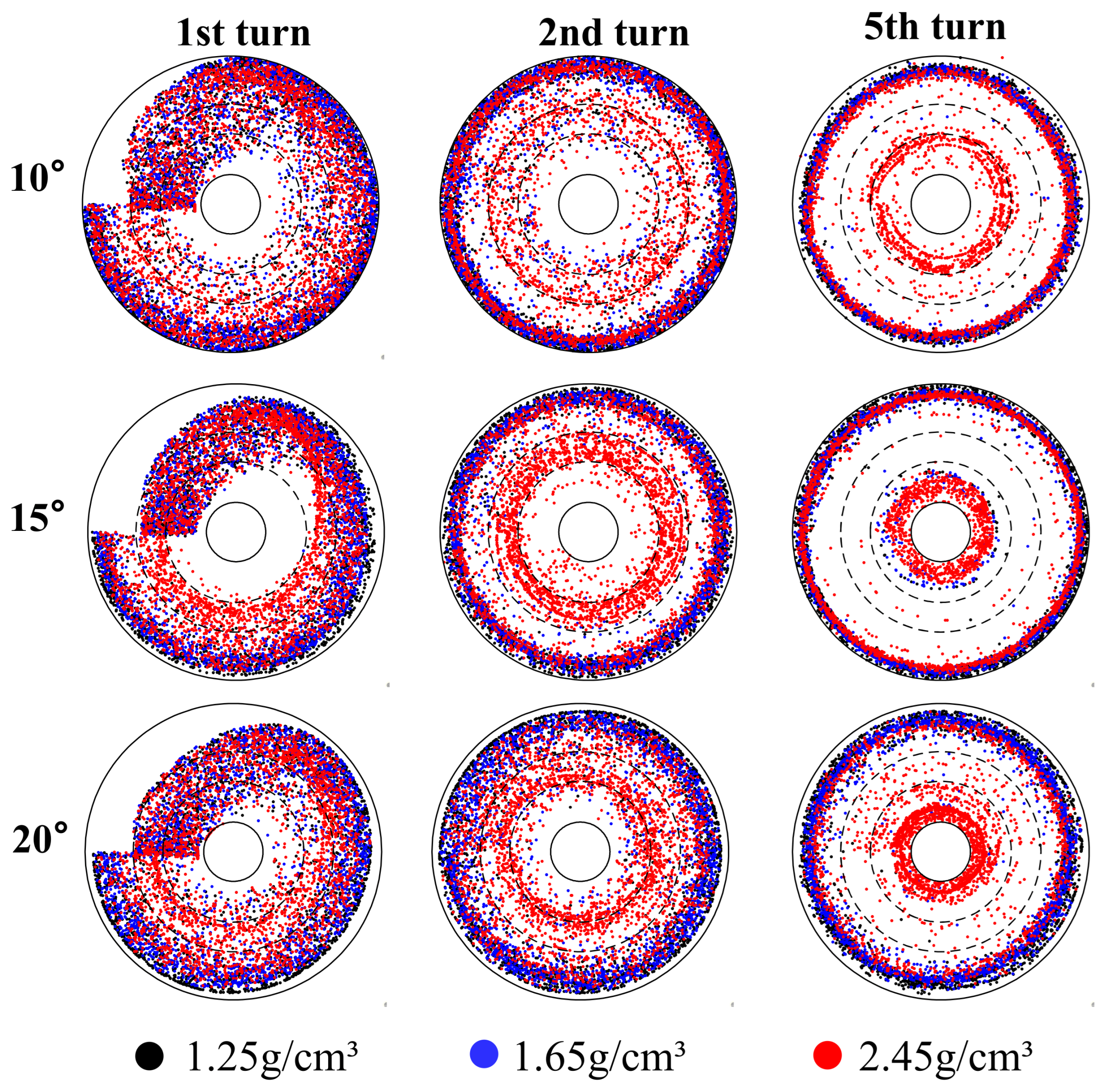
A comparative analysis of the particle distribution patterns under varying transverse inclination angles (10°, 15°, and 20°) across different turns of the spiral separator is presented in Figure 7. While the fundamental segregation mechanism—by high-density particles migrate toward the inner edge while low- and middling-density particles report to the outer region—is conserved across all inclination angles, the transverse inclination exerts a systematic and pronounced influence on the sharpness of the separation and the spatial distribution of the particle bands. Specifically, as the inclination angle increases, middling- and low-density particles collectively migrate toward the inner edge of the spiral trough. Notably, under all tested inclination conditions, contamination from high-density particles is observed within or near the middling- and low-density particle bands at the outermost edge, indicating that particle misplacement is an inherent characteristic of the spiral separation process.
Analysis of the first turn reveals that a transverse inclination of 10° yields a wider radial distribution of particles across the trough surface. As the inclination increases to 15° and 20°, the distribution of all three density classes contracts noticeably toward the inner region. From the second turn onwards, a steeper inclination promotes a sharper separation boundary between the high-density particle band and the middling/low-density particle bands. This is evidenced by a clearer concentration of high-density particles at the inner edge and a marked reduction in the intermixing of high-density particles within the outermost middling/low-density streams.
By the fifth turn, the particle distribution in the outer region stabilizes, while high-density particles continue to concentrate further inward at the inner edge. Comparative analysis confirms that the 20° transverse inclination delivers the optimal separation performance, characterized by a pronounced concentration of high-density particles at the inner edge and a more effective suppression of high-density particle contamination in the outermost product bands.
These findings demonstrate that increasing the transverse inclination angle within an appropriate range effectively enhances separation efficiency by optimizing flow patterns and particle trajectories, thereby strengthening spatial segregation according to density. This insight provides a critical theoretical foundation for the structural optimization of spiral separators.

3.4. Influence of Transverse Inclination Angle on Fine Particles (−0.1 mm) Distribution

In Figure 7, non-negligible fraction of both middling- and high-density particles reports to the outermost edge of the spiral trough, which is consistent with empirical observations in industrial coarse slime processing. This misplacement behavior underscores two inherent challenges in spiral separation. Firstly, the presence of middling-density particles within the outer clean coal zone highlights a fundamental limitation of the gravity-based separation mechanism, which achieves limited efficiency in discriminating between coal and middling-density particles due to their closely matched densities. Secondly, the contamination of the clean coal product by high-density particles is primarily attributable to the presence of excessively fine particles, whose behavior is dominated by fluid drag rather than gravity, thereby compromising the separation efficiency.
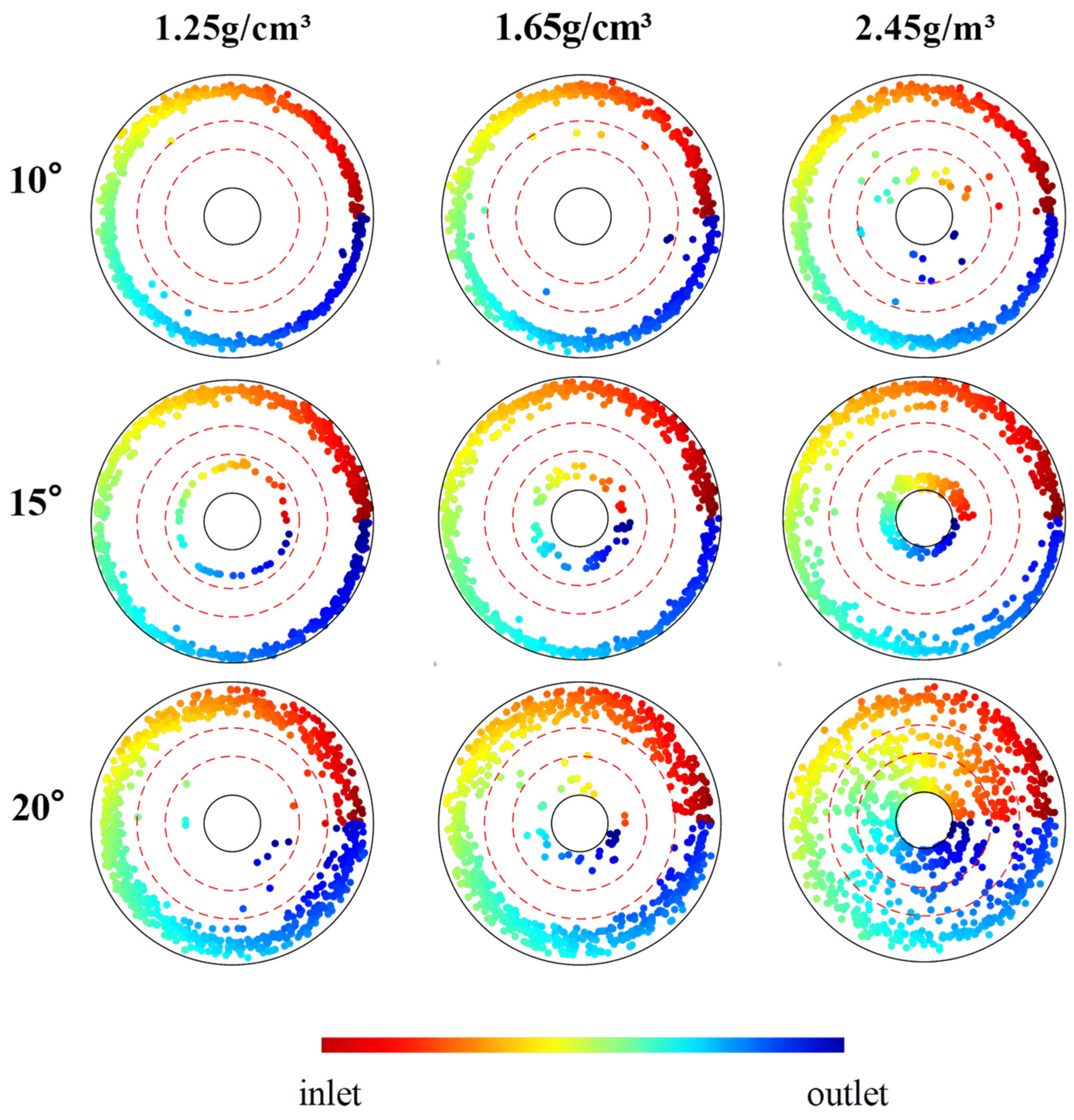
Figure 8 further illustrates how the transverse inclination angle affects the distribution of 0.1 mm particles of different densities within the fifth turn of the spiral trough. The particle color corresponds to the axial position, ranging from red at the entrance of the fifth turn to blue at its exit.
For low-density particles, although the predominant tendency to concentrate near the outer edge persists across all inclination conditions, an increase in inclination promotes a discernible inward migration. This effect is particularly evident under the 20° condition, where the concentrated band of particles along the outer edge becomes noticeably wider compared to the 10° and 15° configurations.
A similar behavioral trend is observed for middling-density particles of the same size. However, the inward migration induced by steeper inclination is more pronounced for middling-density particles than for their low-density counterparts. In contrast, the transverse inclination angle exerts a more substantial influence on the distribution of high-density particles. Increased inclination markedly enhances the inward enrichment of this group, reducing their presence in the outer region.
In summary, even for fine particles as small as 0.1 mm—a size near the practical separation limit of spiral separators—the transverse inclination angle provides a perceptible degree of control over their distribution patterns. Nevertheless, effective density-based separation remains limited at this size range, as indicated by the insufficient radial segregation between light and heavy particles. Despite the overall challenge in achieving effective separation, the consistent trend of inward particle migration with increased inclination is of practical significance. This phenomenon indicates that even for difficult-to-separate fine particles, adjusting the transverse inclination can help mitigate misplacement by reducing the contamination of the outer clean coal product by high-density particles. Consequently, this modulation offers a viable strategy for enhancing the quality of the clean coal stream, even when full separation is not achieved.

4. Conclusions

This study systematically investigated the effect of transverse inclination angle on the spiral separation process, elucidating its dynamic stage-wise characteristics and the misplacement behavior of fine particles. This work addresses a critical knowledge gap by deepening the fundamental understanding of the separation process and clarifying the influence of transverse inclination angle on particle distribution. The main conclusions are as follows:
(1)
The spiral separation process exhibits three distinct dynamic stages: an initial stage (first 1/3 turn) dominated by hydraulic transport, a transition stage (1/3 to 2 turns) where density-based segregation becomes pronounced, and a quasi-steady stage (after 2 turns) characterized by the continuous inward enrichment of high-density particles.
(2)
Increasing the transverse inclination angle to 20° effectively mitigates particle misplacement by optimizing the flow field. This reduces flow fluctuations in the inner zone, widens the high-velocity core, and promotes a clear inward migration of high-density particles, thereby sharpening the separation between different density fractions.
(3)
For challenging fine particles below 0.1 mm, a steeper inclination angle shows a clear reduction in misplacement by enhancing the inward trajectory of high-density particles, even though complete separation remains difficult to achieve.

Author Contributions

Methodology, G.Y. and P.L.; Software, P.L.; Validation, G.Y. and P.L.; Formal analysis, W.L. and P.L.; Investigation, W.L.; Data curation, W.L. and G.Y.; Writing—original draft, W.L.; Writing—review & editing, G.Y.; Supervision, G.Y.; Project administration, G.Y.; Funding acquisition, G.Y. All authors have read and agreed to the published version of the manuscript.

Funding

This research was funded by the China Postdoctoral Science Foundation grant number 2025M781730, the National Natural Science Foundation of China grant number 52104260, and the Research Project Supported by Shanxi Scholarship Council of China grant number 2025-096.

Data Availability Statement

The data presented in this study are available upon request from the corresponding author. The data are not publicly available due to the inclusion of technical details pertaining to the geometry of a custom-built spiral separator.

Conflicts of Interest

Author Wanzhong Liu was employed by the company China ENFI Engineering Corporation, Beijing 100038, China. The remaining authors declare that the research was conducted in the absence of any commercial or financial relationships that could be construed as a potential conflict of interest. Author Penghui Liu was employed by the company Langfang North Tianyu Electromechanical Technology Co., Ltd., Langfang 065000, China. The remaining authors declare that the research was conducted in the absence of any commercial or financial relationships that could be construed as a potential conflict of interest.

References

  1. Yang, M. Evaluation of Ultrafine Spiral Concentrators for Coal Cleaning. Master’s Thesis, West Virginia University, Morgantown, WV, USA, 2010. [Google Scholar]
  2. Ramudzwagi, M.; Tshiongo-Makgwe, N.; Nheta, W. Recent developments in beneficiation of fine and ultra-fine coal—Review paper. J. Clean. Prod. 2020, 276, 122693. [Google Scholar] [CrossRef]
  3. Ma, G.X.; Bu, X.N.; Xie, G.Y.; Peng, Y.L.; Sha, J.; Xia, W.C.; Wu, E.D. Comparative Study of Separation Performance of a Spiral and Dense-medium Cyclone on Cleaning Coal. Int. J. Coal Prep. Util. 2021, 41, 108–116. [Google Scholar] [CrossRef]
  4. Tripathy, S.K.; Murthy, Y.R.; Singh, V.; Farrokhpay, S.; Filippov, L.O. Improving the Quality of Ferruginous Chromite Concentrates Via Physical Separation Methods. Minerals 2019, 9, 667. [Google Scholar] [CrossRef]
  5. Rao, R.B.; Srikant, S.S. Judicious combinations of gravity, magnetic, electrostatic separators and microwave heat energy on recovery of ilmenite from Humma lean grade beach placer deposit. J. Microw. Power Electromagn. Energy 2024, 58, 342–357. [Google Scholar] [CrossRef]
  6. Gao, Y.; Qi, Y.; Zhang, C.; Wang, W.; Tu, Y.; Zhu, Z.; Xu, Z. Combined gravity separation-oil agglomeration separation of coal gasification fine slag and metal elements risk characteristics in separated products. Int. J. Coal Prep. Util. 2025, 46, 381–401. [Google Scholar] [CrossRef]
  7. Izerdem, D. A Comparative Experimental Analysis of the Effect of Spiral Geometry on the Separation of Fine Chromite Particles. Part 2: Image Analysis Application in a High-Capacity Spiral. Min. Metall. Explor. 2025, 42, 3933–3944. [Google Scholar] [CrossRef]
  8. Doheim, M.A.; Abdel Gawad, A.F.; Mahran, G.M.A.; Abu-Ali, M.H.; Rizk, A.M. Numerical simulation of particulate-flow in spiral separators: Part I. Low solids concentration (0.3% & 3% solids). Appl. Math. Model. 2013, 37, 198–215. [Google Scholar] [CrossRef]
  9. Matthews, B.W.; Fletcher, C.A.J.; Partridge, A.C. Computational simulation of fluid and dilute particulate flows on spiral concentrators. Appl. Math. Model. 1998, 22, 965–979. [Google Scholar] [CrossRef]
  10. Ankireddy, P.R.; Purushotham, S.; Narasimha, M. Fluid Flow Modeling and Analysis of Low- and High-Gravity Spiral Concentrators: Experimental and Analytical Approaches. Chem. Eng. Technol. 2023, 46, 1619–1629. [Google Scholar] [CrossRef]
  11. Meng, L.; Gao, S.; Wei, D.; Cui, B.; Shen, Y.; Song, Z.; Yuan, J. Effects of cross-sectional geometry on flow characteristics in spiral separators. Sep. Sci. Technol. 2021, 56, 2967–2977. [Google Scholar] [CrossRef]
  12. Ye, G.; Ma, L.; Alberini, F.; Xu, Q.; Huang, G.; Yu, Y. Numerical studies of the effects of design parameters on flow fields in spiral concentrators. Int. J. Coal Prep. Util. 2022, 42, 67–81. [Google Scholar] [CrossRef]
  13. Ye, G.; Liu, Q.; Ma, L.; Dong, X. CFD-DEM investigation of fluid and particle motion behaviors in initial stage of spiral separation process at low solids concentration. Miner. Process. Extr. Metall. Rev. 2023, 44, 475–480. [Google Scholar] [CrossRef]
  14. Meng, L.; Gao, S.; Wei, D.; Cui, B.; Shen, Y.; Song, Z. Investigation on the evolution of flow field stability in a spiral separator. Miner. Eng. 2021, 174, 107224. [Google Scholar] [CrossRef]
  15. Atasoy, Y.; Spottiswood, D.J. A study of particle separation in a spiral concentrator. Miner. Eng. 1995, 37, 1197–1208. [Google Scholar] [CrossRef]
  16. Li, M.; Wood, C.J.; Davis, J.J. A study of coal washing spirals. Coal Prep. 1994, 12, 117–131. [Google Scholar] [CrossRef]
  17. Boucher, D.; Deng, Z.; Leadbeater, T.; Langlois, R.; Renaud, M.; Waters, K.E. PEPT studies of heavy particle flow within a spiral concentrator. Miner. Eng. 2014, 62, 120–128. [Google Scholar] [CrossRef]
  18. Boucher, D.; Deng, Z.; Leadbeater, T.; Langlois, R.; Waters, K.E. Observation of iron ore beneficiation within a spiral concentrator by positron emission particle tracking of large (Ø = 1440 μm) and small (Ø = 58 μm) hematite and quartz tracers. Chem. Eng. Sci. 2016, 140, 217–232. [Google Scholar] [CrossRef]
  19. Boucher, D.; Deng, Z.; Leadbeater, T.W.; Langlois, R.; Waters, K.E. Speed analysis of quartz and hematite particles in a spiral concentrator by PEPT. Miner. Eng. 2016, 91, 86–91. [Google Scholar] [CrossRef]
  20. Abdel Gawad, A.; Mahran, G.; Doheim, M.; Ali, M.A.H. CFD simulation of particulate flow in a spiral concentrator. Mater. Test. 2015, 57, 811–816. [Google Scholar] [CrossRef]
  21. Mishra, B.K.; Tripathy, A. A preliminary study of particle separation in spiral concentrators using DEM. Int. J. Miner. Process. 2010, 94, 192–195. [Google Scholar] [CrossRef]
  22. Kwon, J.; Kim, H.; Lee, S.; Cho, H. Simulation of particle-laden flow in a Humphrey spiral concentrator using dust-liquid smoothed particle hydrodynamics. Adv. Powder Technol. 2017, 28, 2694–2705. [Google Scholar] [CrossRef]
  23. Sudikondala, P.; Mangadoddy, N.; Tripathy, S.K.; Yanamandra, R.M. CFD modelling of the spiral concentrator at moderate feed solids content-prediction of particle segregation. Trans. Indian Inst. Met. 2024, 77, 4193–4204. [Google Scholar] [CrossRef]
  24. Meng, L.; Gao, S.; Wei, D.; Zhao, Q.; Cui, B.; Shen, Y.; Song, Z. Particulate flow modelling in a spiral separator by using the Eulerian multi-fluid VOF approach. Int. J. Min. Sci. Technol. 2023, 33, 251–263. [Google Scholar] [CrossRef]
  25. Gao, S.; Zhou, X.; Meng, L.; Zhao, Q.; Liu, W. Variation of Flow Hydrodynamic Parameters and Prediction of Particle Separation Indices in the Spiral Concentrator with the Regulation of Pitch-Diameter Ratio. Separations 2023, 10, 410. [Google Scholar] [CrossRef]
  26. Xia, M.; Ye, G.; Liu, Q.; Dong, X.; Fu, Y.; Ma, X.; Liu, S.; Chen, R.; Zhang, C.; Zhu, B. Stage-Optimized Intensification of Spiral Separation: Process Deconstruction and a Novel Spiral Separator Design. Minerals 2026, 16, 153. [Google Scholar] [CrossRef]
  27. Loveday, G.K.; Cilliers, J.J. Fluid flow modelling on spiral concentrators. Miner. Eng. 1994, 7, 223–237. [Google Scholar] [CrossRef]
  28. Ansys Inc. Ansys Fluent Theory Guide; Ansys Inc.: Canonsburg, PA, USA, 2011; pp. 724–746. [Google Scholar]
  29. Abhilash; Usha, Y.; Seetharaman, K.; Meshram, P.; Mehta, K.D.; Pandey, B.D. Application of Hydrodynamics Using CFD in Evaluating Efficacy of External Loop Air-lift Reactor Biochemical Leaching of Sea Nodules. Miner. Process. Extr. Metall. Rev. 2022, 43, 892–898. [Google Scholar] [CrossRef]
  30. Ma, L.; Wei, L.; Pei, X.; Zhu, X.; Xu, D. CFD-DEM simulations of particle separation characteristic in centrifugal compounding force field. Powder Technol. 2019, 343, 11–18. [Google Scholar] [CrossRef]
  31. Mingyang, S.; Lubin, W.; Xueshuai, Z.; Dahu, L.; Yang, L.; Junli, L. Simplification and application of particles kinetic equationfor liquid-solid fluidized bed separator. J. Cent. South Univ. (Sci. Technol.) 2018, 49, 1307–1314. [Google Scholar] [CrossRef]
  32. Agrawal, V.; Shinde, Y.; Shah, M.; Utikar, R.; Pareek, V.; Joshi, J. Effect of drag models on CFD-DEM predictions of bubbling fluidized beds with Geldart D particles. Adv. Powder Technol. 2018, 29, 2658–2669. [Google Scholar] [CrossRef]
  33. Suzzi, D.; Toschkoff, G.; Radl, S.; Machold, D.; Khinast, J.G. DEM simulation of continuous tablet coating: Effects of tablet shape and fill level on inter-tablet coating variability. Chem. Eng. Sci. 2012, 69, 107–121. [Google Scholar] [CrossRef]
  34. Barrios, G.K.P.; De Carvalho, R.M.; Kwade, A.; Tavares, L.M. Contact parameter estimation for DEM simulation of iron ore pellet handling. Powder Technol. 2013, 248, 84–93. [Google Scholar] [CrossRef]
  35. Just, S.; Toschkoff, G.; Funke, A.; Djuric, D.; Kleinebudde, P. Experimental Analysis of Tablet Properties for Discrete Element Modeling of an Active Coating Process. AAPS PharmSciTech 2013, 14, 402–411. [Google Scholar] [CrossRef]
Figure 1. Schematic diagram of the experimental set-up and the flow depth measurement rig [27].
Separations 13 00073 g001
Figure 2. Computational grid and mesh independence study.
Separations 13 00073 g002
Figure 4. Validation of the numerical model against experimental data.
Separations 13 00073 g004
Figure 5. Dynamic evolution of flow field velocity and particle distribution across the full spiral separation process.
Separations 13 00073 g005
Figure 6. Influence of transverse inclination angles on the flow field velocity distribution.
Separations 13 00073 g006
Figure 7. Influence of transverse inclination angles on the distribution of particles.
Separations 13 00073 g007
Figure 8. Distribution of 0.1 mm particles in the fifth turn under different transverse inclination angles.
Separations 13 00073 g008
Table 1. Summary of all key parameters used in the CFD-DEM simulations.
CategoryParameterValue/ModelDescription/Justification
Fluent SettingsTurbulence ModelRNG k-εSelected for its accuracy in simulating swirling flows.
Wall TreatmentStandard Wall FunctionsApplied for near-wall flow modeling.
Inlet BoundaryVelocity InletCorresponding to experimental flow rate.
Outlet BoundaryPressure OutletSetting Backflow Volume Fraction of 1
upwallFree-Slip WallAssumes negligible wall friction for the fluid.
Bottom WallNo-Slip WallStandard stationary wall condition.
Solver & Time StepPressure-Based, TransientTime step size: 0.0001 s.
EDEM SettingsParticle Densities1.25, 1.65, 2.45 g/cm3Representing low-, middling-, high-density coal.
Particle Size Distribution0–1.5 mm——
Particle-Particle/Wall ContactCalibratedTrough material: Fiberglass; Calibrated via Response Surface Methodology (RSM).
Particle Contact ModelHertz-Mindlin (no slip)Default model in EDEM for particle-particle and particle-wall collisions.
Particle Injection600 particles/secondMass flow rate calibrated to achieve a solid concentration of 1%.
Particle Volumetric ForcesCustom APIForces include fluid drag (via dynamic drag coefficient) and pressure gradient force.
Data ExchangeEvery 20 CFD stepsCoupling interval ensures numerical stability and solution accuracy.
Table 2. Key governing equations employed in the CFD-DEM model.
Force and MomentRemarkSymbolEquation
Normal forceContact force f c n , i j E 3 ( 1 u p 2 ) 2 R i δ n 1.5 n
Non-contact force f d n , i j C n ( 3 m i E 2 ( 1 u p 2 ) R i δ n ) 0.5 u n , i j
Tangential forceContact force f c t , i j { μ p f c n , i j / | δ t | } [ 1 ( 1 m i n { | δ t | , δ t , m a x } / δ t , m a x ) 1.5 ] δ t
Non-contact force f d t , i j C t ( 6 m i μ s | f c n , i j | 1 δ t / δ t , m a x δ t , m a x ) 0.5 u t , i j
MomentTranslation T t , i j R i × ( f c t , i j + f d t , i j )
Rotation T r , i j μ r | f c n , i j | ω ^
Volumetric forceGravitational force G i j m i g
Particle–fluid interaction force f p f , i 3 4 ( 0.63 + 4.8 R e p 0.5 ) 2 ρ f ε p | u p u | d p ε f ε | u p u |
ε = 3.7 0.65   e x p [ ( 1.5 l o g   R e p ) 2 2 ]
Pressure gradient force F p V p , i · P
where n = R i R i , u i j = u i u j + ω j × R j ω i × R i , u n , i j = ( u i j × n ) × n , ω ^ i = ω i ω i
Table 3. Calibrated contact parameters for the DEM model.
TypeCoefficient of RestitutionStatic Friction CoefficientKinetic Friction Coefficient
Low-density particle–Low-density particle0.130.440.1
Low-density particle–High-density particle0.150.450.17
Low-density particle–Fiberglass (trough material)0.20.50.1
Low-density particle–Middling-density particle0.140.440.15
Middling-density particle–Middling-density particle0.150.450.15
Middling-density particle–High-density particle0.20.450.18
Middling-density particle–Fiberglass0.20.50.1
High-density particle–High-density particle0.20.50.2
High-density particle–Fiberglass0.250.50.1
Disclaimer/Publisher’s Note: The statements, opinions and data contained in all publications are solely those of the individual author(s) and contributor(s) and not of MDPI and/or the editor(s). MDPI and/or the editor(s) disclaim responsibility for any injury to people or property resulting from any ideas, methods, instructions or products referred to in the content.