Article

An Empirical Study on the Upcycling of Glass Bottles into Hydrocyclone Separators

1
Department of Environmental, Process & Energy Engineering, MCI—The Entrepreneurial School, 6020 Innsbruck, Austria
2
Department of Medial & Health Technologies, MCI—The Entrepreneurial School, 6020 Innsbruck, Austria
3
Department of Industrial Engineering, MCI—The Entrepreneurial School, 6020 Innsbruck, Austria
*
Author to whom correspondence should be addressed.
Separations 2024, 11(8), 230; https://doi.org/10.3390/separations11080230
Submission received: 12 June 2024 / Revised: 19 July 2024 / Accepted: 25 July 2024 / Published: 26 July 2024
(This article belongs to the Section Purification Technology)

Abstract

:
Cyclones are pivotal in mechanical process engineering and crucial in the complex field of separation technology. Their robustness and compact spatial requirements render them universally applicable and versatile across various industrial domains. Depending on the utilized fluid and field of application, both gas-based cyclones and hydrocyclones (HCs) are well established. Regarding HC design, enduring elongated flat cones have seen minimal alterations in shape and structure since their introduction over more than a hundred years ago. Experimental investigations regarding unconventional cone designs within scientific studies remain the exception. Therefore, this study focuses on alternative geometric configurations of the separation chambers and highlights their impact on separation and energy efficiency. To achieve this objective, different geometric shapes are investigated and retrofitted into HCs. The geometric foundation is derived from upcycled glass bottles. The repurposed bottles with a volume of 750 mL are used in conjunction with an inlet part, following the established Rietema design. Experimental tests are conducted with dilute phase separation, using 0.1–200 µm test particles in water. Comparisons between a bottle-based HC and a conventional Rietema design were conducted, establishing a benchmark against the standard. The findings revealed a noticeable correlation between separation efficiency and cone geometry. Conical designs demonstrated enhanced separation, particularly at lower volume flows. At the highest volume flow of 75 L min−1, the best performing bottle cyclones showed separation efficiencies of 78.5%, 78.4% and 77.9% and therefore are in a competitive range with 78.0% efficiency, achieved using the commercial Rietema design. Minimal disparities in cut sizes were observed in terms of separation grade efficiency among the models tested. Variations in separation efficiency and fractional efficiency curves indicated nuanced differences in classification efficiency.

1. Introduction

The versatility of hydrocyclones (HCs) encompasses solid–liquid and liquid–liquid separation, stemming from their initial recognition in the mining industry pioneered by Eugene Bretney [1]. Adaptations to their geometry enhance their performance, leading to broad applications across mechanical, chemical, environmental, and biotechnological engineering. The fundamental principle of both gas cyclones and hydrocyclones is similar, relying on separation through centrifugal forces [2,3,4]. In an HC, a liquid loaded with solid particles (suspension) undergoes a strong rotational motion due to the laterally offset inlet. An external vortex forms, spiraling along the cyclone wall into the lower section—the cone. The density difference between solid and liquid components, coupled with centrifugal forces, accumulates the solid particles at the narrowing part of the cone, where they are discharged. As a minimal volume of concentrated suspension exits the underflow, the lower concentration suspension exits axially via the cyclone’s vortex finder, creating an internal vortex. This configuration, due to the reversal of the two main flows in the cyclone’s separation chamber, is known as a countercurrent cyclone. Notably, this countercurrent principle allows for highly efficient particle separation. Cyclonic separation remains pivotal due to operational efficacy, utilizing centrifugal forces to isolate dispersed solid particles in fluids. Its basic design with relevant variables is depicted in Figure 1.
Centrifugal forces can reach up to 10,000 g in a 20 mm diameter HC [1], separating particles typically ranging from 5 to 250 μm [5]. The devices find utility in various sectors, from mining and mineral processing [6] to petroleum [7,8], wastewater treatment [9], microplastic mitigation [10], flue gas desulfurization [1], and food processing, among others [11]. Their compact design and low-maintenance operation contribute to their widespread adoption. Constructed with non-rotating parts, these cyclones are modular, enabling easy part replacement and post-assembly modifications for tailored performance. Materials used depend on the handled suspension: coatings are applied for abrasion resistance, while stainless steel, plastics, or ceramics serve in non-coated cyclones [5,12,13].
In solid–liquid separation, HCs serve mainly clarification (yielding mostly solid-free overflow) or thickening (mostly solid-rich underflow) purposes [1]. Efficient separation distinguishes between dispersion removal and classification, aiming for high efficiency with minimal misplacement [14]. Innovative cone designs aim for small separation cut sizes through optimized geometries, enhancing tangential velocity and residence time [5,12]. Regarding small separation cut sizes, Schubert [5] points to newly developed combined cone geometries comprising consecutive varying angles. As a result, improvements in separation efficiency are achieved due to maximized tangential velocity in the upper cyclone section and prolonged residence time in the lower cyclone segment [12]. Prior scholarly works by Jiang et al. [15] conducted experimental investigations using composite curved cones, which were largely successful and applied in practical applications. Yang et al. [16] combined various angles within a single cone. Similarly, Ghodrat et al. [17] explored, through numerical analysis using computational fluid dynamics (CFD), the impact of convex and concave cones on pressure drop and particle separation. They obtained favorable results for long convex cones compared to conventionally modeled separation bodies. Vimal et al. [18] also investigated convex and concave-shaped cones, both with and without solid cores, as well as unconventional adaptations in the vortex finder of the inlet section. They determined in-field recommendations that depend mainly on particle size.
All of the mentioned studies, along with many others, are integrated into a comprehensive review by Ni et al. [19], which provides a thorough state-of-the-art summary of HC technology and optimization regarding geometric parameters. This review investigates all geometric factors influencing the separation efficiency in both single and multi-HC arrangements. Within the study, both simple and conventional designs are presented alongside more sophisticated adaptions such as spiral inlets with moving guide plates [20] or novel tangent circle inlets [21]. It concludes that while the efficiency of HCs can be drastically improved, optimizations developed for specific applications are often restricted to those applications. Additionally, the use of multiple separate chambers (or channels) can enhance particle separation, as thoroughly investigated by Chlebnikovas et al. and Raimondas et al. [22,23,24]. Optimization studies like those mentioned do not always focus solely on increasing separation efficiency. Operational efficiency, influenced by effects such as clogging due to adhesion, can be improved with geometric adaptations or additional installations, as thoroughly investigated by Zhou et al. [25,26,27]. However, in-depth investigations regarding drastically unconventional cone designs remain scarce. In the context of preceding contributions that explored different cone designs, the idea of this study is to focus on alternative geometric configurations of separator chambers and highlight their impact on separation and energy efficiency.
This present study focuses on the geometric design of the cone and subsequently on the impact on separation behavior and HC operation when utilizing unconventional cone designs. Upcycled glass bottles, which are the center of the investigation, exhibit maximum diversity and possess a hydrodynamic design without abrupt steps or expansions. The emphasis of the experimental evaluation lies in the resulting pressure drop investigation across the cyclones, the separation efficiencies and the sharpness of the individual fractional separation efficiencies. To facilitate a realistic and valid comparison between cone shapes, an experimental setup is devised. The basic cyclone’s construction follows the Rietema design principles [28].

2. Materials and Methods

2.1. Experimental Setup

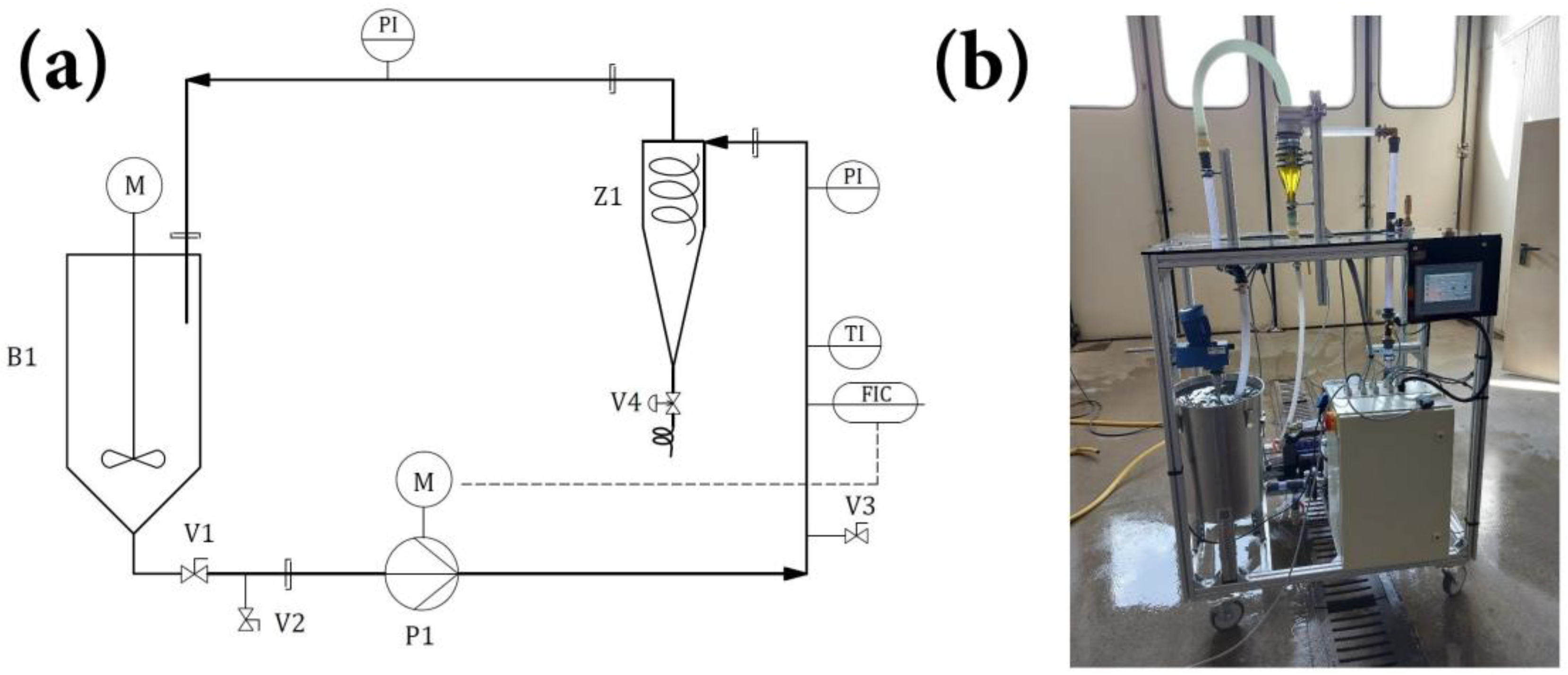
The experimental setup, illustrated in Figure 2, utilizes bonded 1″ PVC tubes for pipelines, featuring screw connections for measuring instruments and valves. The space accommodation of the interchangeable HC (Z1) is provided by flexible plastic hoses. A 1.3 kW pump (P1) delivers 5.4 m3 h−1 with a 55 m head, regulated by the pump motor’s speed (M). The suction line between the 30 l stirred tank (B1) and multi-stage centrifugal pump is minimized. Control is managed via the Siemens Simatic panel KTP700 and the Simatic S7-1200, adjusting volume flow and intermittent discharges through a pneumatically controlled valve (V4). Manual valves (V1, V2 and V3) aid system drainage. Instrumentation includes two pressure indicators (PIs) before and after the HC for pressure drop measurement, as well as a combined flow indication and control unit (FIC) with an integrated temperature indicator (TI). Both PIs utilize a thick-film ceramic measuring cell, deforming under pressure to alter electrical resistance, offering corrosion resistance and stability but sensitive to minor overload and potential sealing issues [29]. The AS009 FIC (accuracy ±0.2%) uses vortex shedding, measuring 5.0 to 85.0 L min−1, allowing suspension temperature measurements via a Pt 1000 element. Outputs were set as 4 to 20 mA analog signals, enabling flow rate adjustment via a PI controller. Measurement relies on the Kármán vortex street principle, depicting vortex shedding behind flow obstacles [29].

2.2. Separation Chamber, Connecting System and Inlet Section

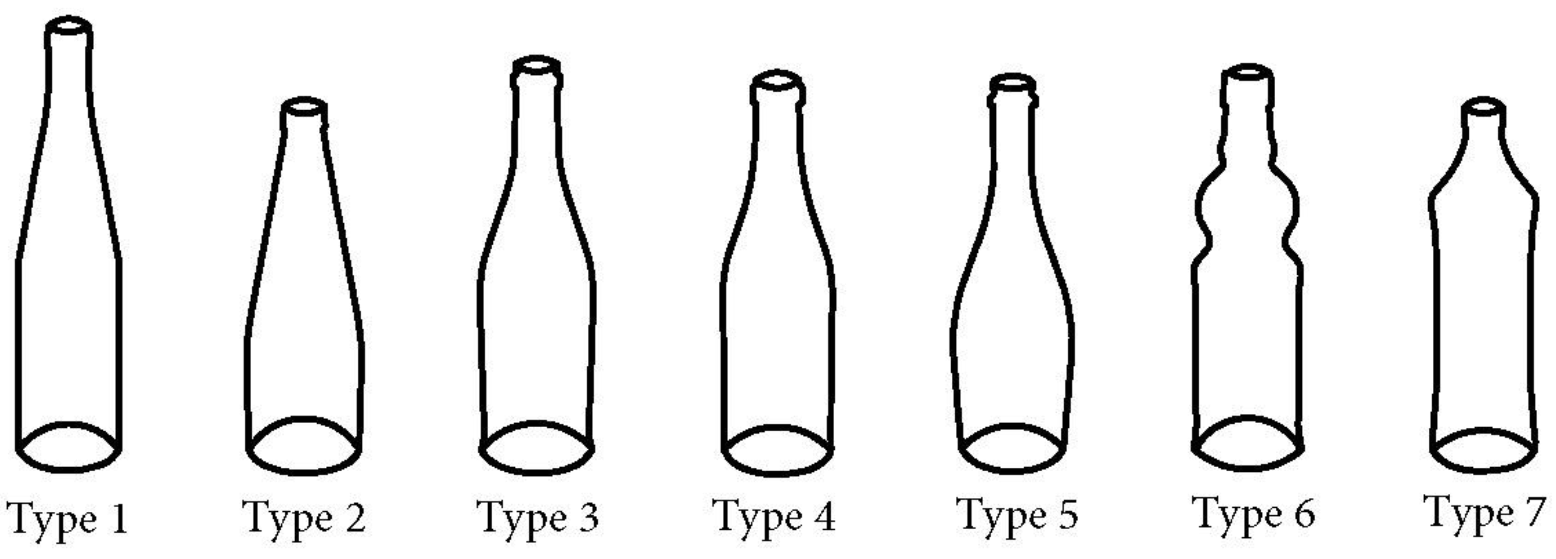
The cyclone test setup comprises two components: firstly, a bottle that needs to be modified to create the separation chamber, and secondly, an upper part containing the tangential inlet and the vortex finder. The utilized bottles have predetermined shapes, requiring a consistent concept for their conversion into cyclone cones. Given the varying lengths and diameters of beverage bottles, achieving cohesive integration as the cyclone body can be accomplished by maintaining an equal volume. The bottle wall thickness varies notably, typically ranging from 3 to 5 mm. The selected bottles for the experimental setup hold a volume of approximately 750 mL each. This volume generally results in bottle diameters ranging from 70 to 75 mm. HCs with diameters ranging from 50 to 100 mm are commonly found in the literature as experimental scales [7]. Furthermore, this size offers a variety of distinct bottle designs. The bottles and their distinctive shapes (conical, curved and cylindrical) which are selected for the experiments can be schematically represented as shown in Figure 3. Further geometric information is found in Table 1.
Consequently, the separation chamber provides an approximately equivalent suspension dwell time, aiming to establish uniform conditions for experimental procedures. Inevitably, this results in a discrepancy in cyclone length, which is accepted within the scope of the presented study. Regarding the cyclone diameter, emphasis is placed on the inlet section, where a predetermined diameter is applicable. Consequently, this necessitates uniform inlet and vortex finder sizes for all bottle types. Therefore, the fluid velocity and formation of flow paths are almost identical in the upper part of the cyclones. As a result of the two cyclone components mentioned—the inlet and cone—there arises a need for a connecting system. Various alternatives exist for this connection, as illustrated in Figure 4. Experimental runs demonstrated that connections using hose clamps, as illustrated in Figure 4C, are more practical, efficient, and air-tight compared to welded joints and simple clamp joints, shown in Figure 4A and Figure 4B, respectively. Additionally, hose clamp connections can bridge the gap caused by the transition between the constant diameter of the inlet section and the varying diameters of the glass bottles, d H C , as documented in Table 1. Therefore, the connection for all experimental runs is realized with hose clamps as depicted in Figure 4C.
Finally, the dimensions for the inlet and vortex finder diameter are derived from the cyclone diameter using the Rietema design (Table 2), further allowing for the calculation of the vortex finder depth. The Rietema design is a well-established and recognized method for designing an HC, focusing on optimized efficiency using specific geometric ratios [28]. Compared to the simpler and more cost-effective Bradley design [3], the more complex Rietema design is predominantly used to achieve higher separation efficiencies. However, accurately translating the Rietema geometry to practical cyclone applications is only partially achievable. The inlet section’s parameters can be fully replicated as it needs to be newly fabricated.
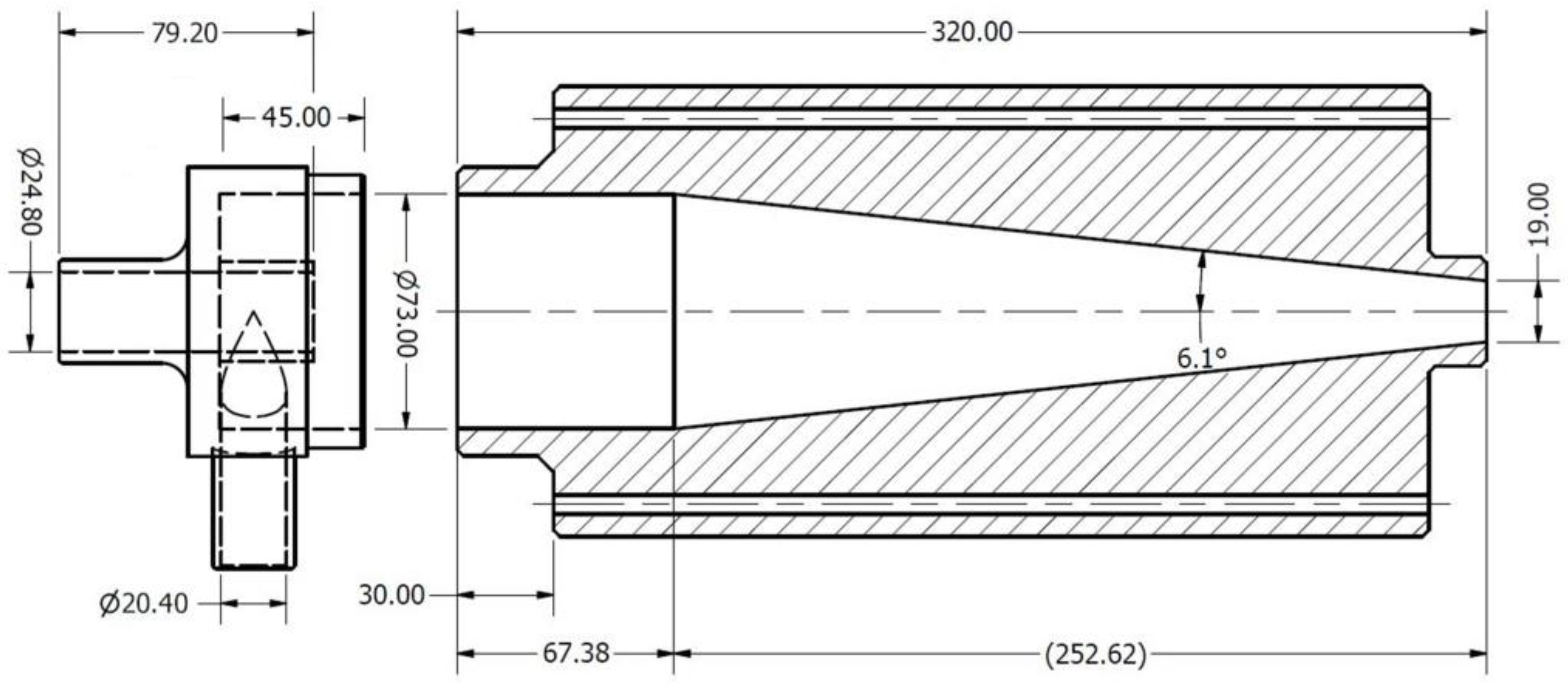
Upon the selection of bottle shapes, an HC diameter ( d H C ) of 73 mm is determined. This diameter lies between the minimum and maximum inner diameters of the bottles and serves as the starting measurement for calculations. The resulting dimensions at the inlet area of the HC are as follows: d H C = 73.00 mm, d I = 20.44 mm, d O = 24.82 mm, h V F = 29.20 mm. Therefore, the dimensions of the component are established. The only remaining parameter is the total height of the inlet component ( h I ). As bottle designs typically include a significant cylindrical component, the inlet part itself is kept as short as possible, and the height measurement ( h I ) is set at 45 mm. The inlet component depicted in Figure 5 was actualized using 3D printing technology due to its complexity.
To facilitate a comparison with a conventional cyclones, an additional cone is manufactured also following the standard Rietema design same as already applied at the inlet section. This cone is crafted from solid PVC material and, like the bottle cones, is adapted to fit the inlet component. Consequently, for the experimental trials, Type 8 with a set volume of 750 mL is introduced, which, in the results and analyses, will be interpreted as the Type 8 Rietema HC. Figure 6 depicts the sample cyclone with the proportionate adaptations. Only the cone is manufactured, intended to be later attached to the existing inlet component to form the complete Rietema cyclone. Accordingly, an adjustment is made to adapt the conventional cone to the inlet component. The diameter of the inlet component, 73 mm, is continued onto the cone. Moreover, the cylindrical shape is extended a few centimeters to allow for a seal at the connection point. The assembly of the inlet element follows the same procedure as that of the bottle bodies.

2.3. Operational Parameters and Experimental Procedure

The operational parameters for the experimental investigations were established following preliminary trials. The suspension’s volumetric solid concentration (concentration of the inlet feed cI = 2.5 g L−1) is set at under 0.1% ( φ s = 0.00093 ) so that the separation process operates within an explicit dilute stream separation regime. In the dilute stream regime, which typically is described with a solid fraction φS < 0.1 (10%), the solids insignificantly affect the fluid flow behavior [30,31]. The solid fraction can be calculated according to Equation (1) using
φ s = V p V f   = m p ρ   ·   V f   = 0.075   k g 2700   k g   m 3 · 0.03   m 3 = 0.00093
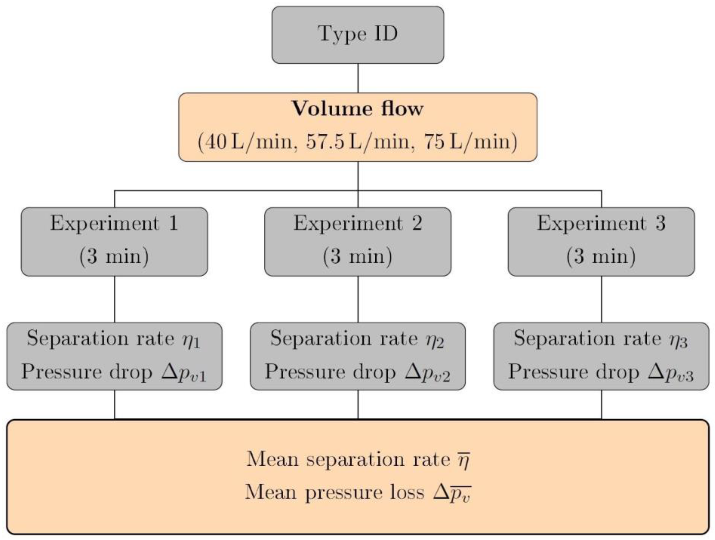
Moreover, this dilute stream separation aims to highlight disparities in the cyclone’s separation performance without turbulence damping, which is common in dense stream separation [5]. Dense stream separation is usually defined with solid fractions of φS > 0.2–0.3 and needs specific consideration because of the increased influence of the solid particles on the fluid flow. The underflow-to-overflow ratio is also set at 1% to reduce discharge at the underflow and, subsequently, liquid loss from the system. Experiments are conducted at three different feed flow rates with 40 L min−1, 57.5 L min−1, and the highest flow rate of 75 L min−1, respectively. Before each experimental run, the HC is emptied to ensure no remaining particles. Moreover, 75 g Carolith 0–0.2 dissolved in 30 L water (cI = 2.5 g L−1) is used as feed material and mixed for 20 s before the separation assessment. After 18 s, underflow discharge is initiated using the interval-controlled pneumatic valve at the underflow. The final underflow discharge occurs after 3 min, followed by experiment termination by flushing and resetting the system. After the experiment, the suspension is allowed a minimum of 12 h to settle to ensure complete solid sedimentation. Subsequently, most of the water is decanted, and any remaining water is removed using a 60 mL syringe. Finally, the remaining damp solid is dried until the Carolith coarse material becomes powdery. The experimental procedure is summarized in Figure 7.
Particle size distribution (PSD) analysis is conducted using laser diffraction using a Mastersizer 2000 (accuracy 0.6%) for both Carolith 0–0.2 as the inlet material and the coarse section after the separation process. Water is used as dispersant, with a refraction index (RI) of 1.330. Particle RI is set with 1.572. PSD or distribution density ( q I ( d p ) ) as well as cumulative distribution ( Q I ( d p ) ) of the inlet section, as well as of the coarse section ( q C ( d p ) , Q C ( d p ) ) are subsequently used to calculate the fractional efficiency, T ( d p ) , with the dimensionless mass fractions of the coarse and fine section, C and F, respectively (Equations (2) and (3)). Separation efficiency η is calculated with the mass of the coarse section (mC) and inlet material (mI) (Equation (4)).
q I ( d p ) = ( 1 η   ) · q F ( d p ) + η   · q C ( d p ) = F · q F ( d p ) + C · q C ( d p )    
T ( d p ) = η   · Q C ( d p ) Q I ( d p ) = G · q C ( d p ) q I ( d p )  
η = m C m I  
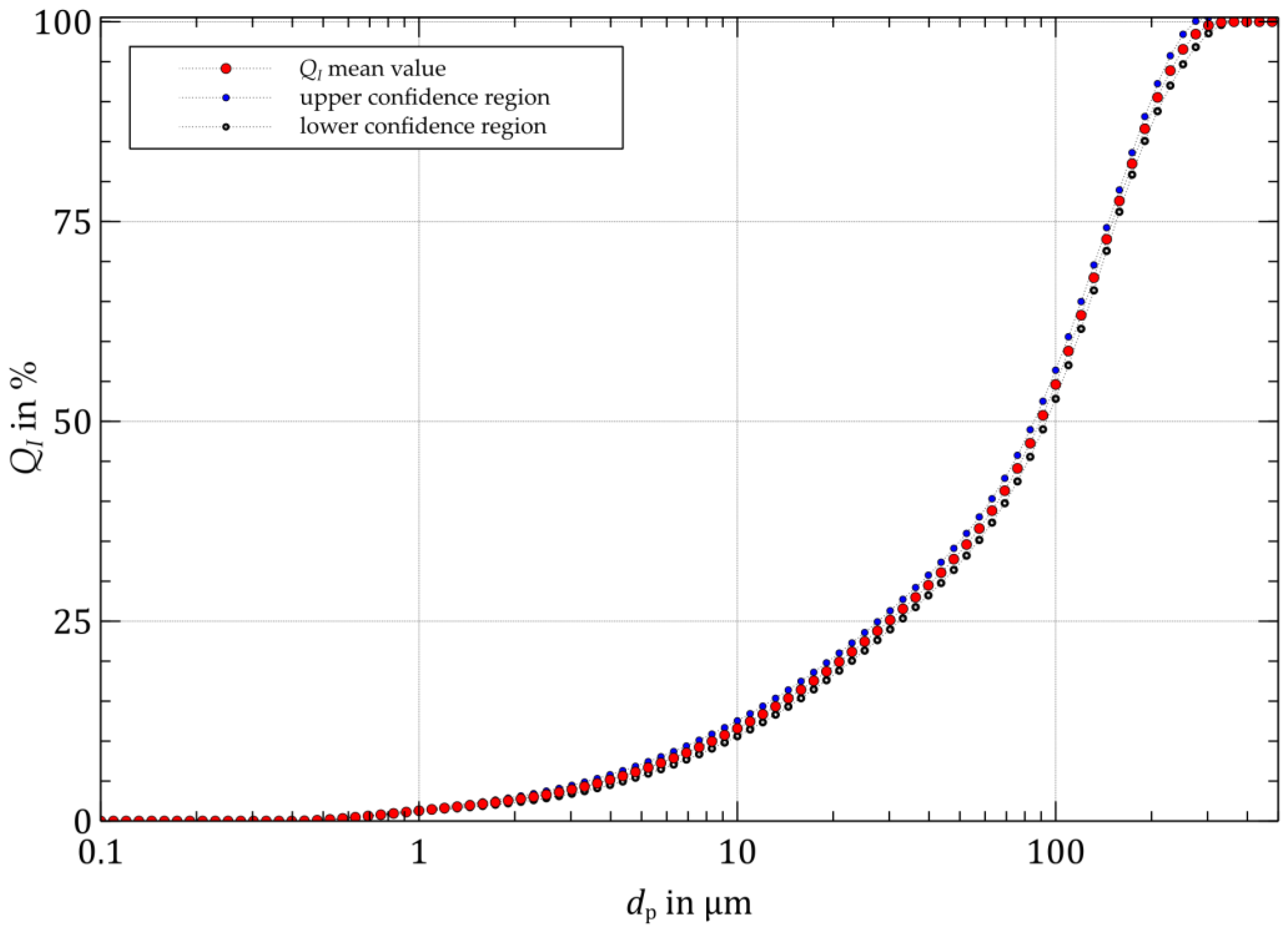
The particle size analysis, QI, of the inlet feed, I, using Carolith 0–0.2 is displayed in Figure 8.

3. Results

Boundary Conditions of Hydrocyclones

In the following chapter, theoretical parameters of the system are presented in order to provide a comparison between the calculated particle cut size ( d C S ) and the actual experimental results. The circumferential velocity at the outer radius of the cyclone inlet section corresponds to the inlet velocity, v I , through the cyclone inlet nozzle. According to maximum volume flow,   V ˙ f , of 75 L min−1 and the cross-section of the inlet, A I , of 3.28 · 10−4 m2, the linear velocity of the suspension at the inlet is equal to 3.81 m s−1 (Equation (5)).
v I   = V ˙ f A I = 3.81   m   s 1
Acceleration factor z i within the inner vortex is calculated utilizing certain assumptions. The law applicable to a vortex flow, v t g · r w = c o n s t , is applied, using the tangential velocity v t g , radius r and a consideration of friction with the exponent w = 0.5. From this, the centrifugal acceleration, a z i , within the inner vortex can be derived (Equation (6)).
a Z i   = v I 2 r H C r I 2 = 3440   m   s 2
The inner radius, r I , is adopted as the radius of the vortex finder, approximately corresponding to the size of the inner vortex flow [32]. Thus, within the inner vortex, centrifugal accelerations of approximately 3440 m s−2 prevail. The ratio of centrifugal acceleration to gravitational acceleration allows the determination of the acceleration factor of Z I = 350.7. This factor prevents the re-mixing of particles that have already been separated in the outer vortex. Another point of interest is comparing d C S , determined mathematically using Schubert’s model (Equation (7)), with the experimental d C S   derived from the separation curve [5]. This retrospective comparison aims to roughly classify the experimental cyclones among recognized standard configurations.
d C S = K   η f ·   d H C   · ln V ˙ O V ˙ U 1 φ A 4.65 · ρ p ρ f   · p I ρ S
To simplify matters, several factors are condensed into the constant K. In a thin-stream separation, K assumes values between 0.10 and 0.15. The particle density, ρ p , of the marble dust Carolith 0–0.2 is approximately 2700 kg m−3. The cyclone inlet pressure, p I , is derived from Cyclone Type 8 at a flow rate of 75 L min−1. The suspension density, ρ S , can be equated to the fluid density, ρ f , which is 1000 kg m−3 due to the low loading.
d C S = 0.15 0.001   P a   s · 0.0365   m · ln 1.236 · 10 3 m 3 s 1 1.4 · 10 5 m 3 s 1 1 0.001 4.65 · 2700   k g   m 3 1000   k g   m 3 · 1.566 10 5   P a 1000   k g   m 3
The calculation of d C S (Equation (8)) yields 23 μm for a K value of 0.15 and 16 μm for a K value of 0.10. Comparing these results with the experimental separation curve, which shows particle sizes between approximately 17 and 19 μm, indicates that the test cyclones demonstrate acceptable fractional separation and separation efficiency, establishing comparability with existing models. A diagram matrix (Figure 9) was constructed to highlight the result values, correlating separation efficiencies and pressure losses. The detailed results are also documented in Table 3.
Rectangular data points represent the averaged separation efficiency calculated from the weight of the dried marble dust Carolith 0–0.2. Error bars denote the highest and lowest calculated separation efficiencies from three experimental runs. The pressure loss data were overlaid as circular data points using a similar method. Connecting lines between different flow rates aid the visualization but do not imply functions or intermediate values.
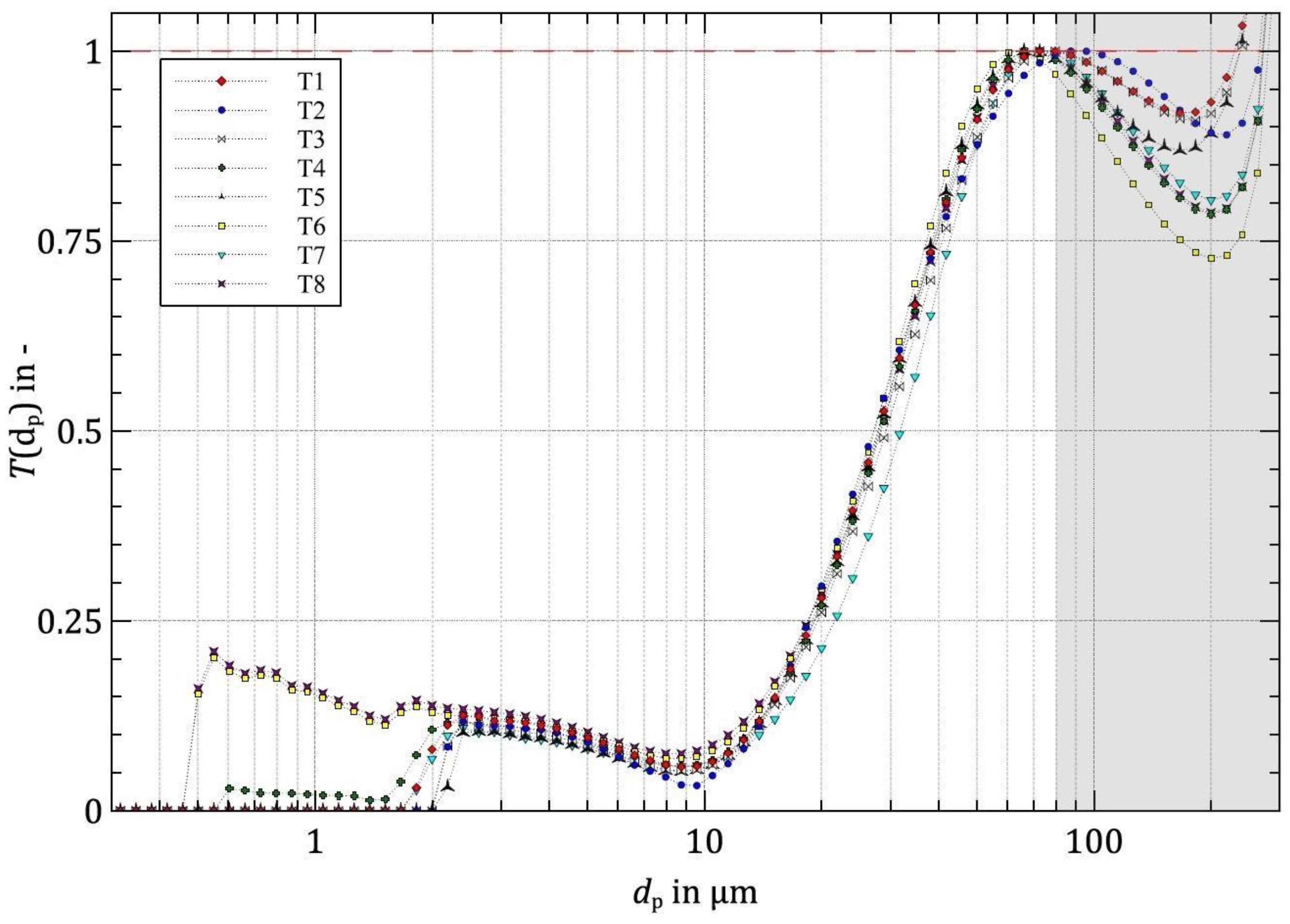
The determined fractional efficiency curves for all cone models are categorized according to the three volume flow rate settings used. Beginning with the flow rate of 40 L min−1, Figure 10 illustrates that the cut particle diameters range between approximately 29 and 34 μm. The shapes of the fractional efficiency curves differ minimally, except for Types 6 and 8. Those fractional efficiency curves exhibit a renewed increase in the functional graph in the fine particle range. Raw data (particle size distributions) can be found in the Supplementary Material.
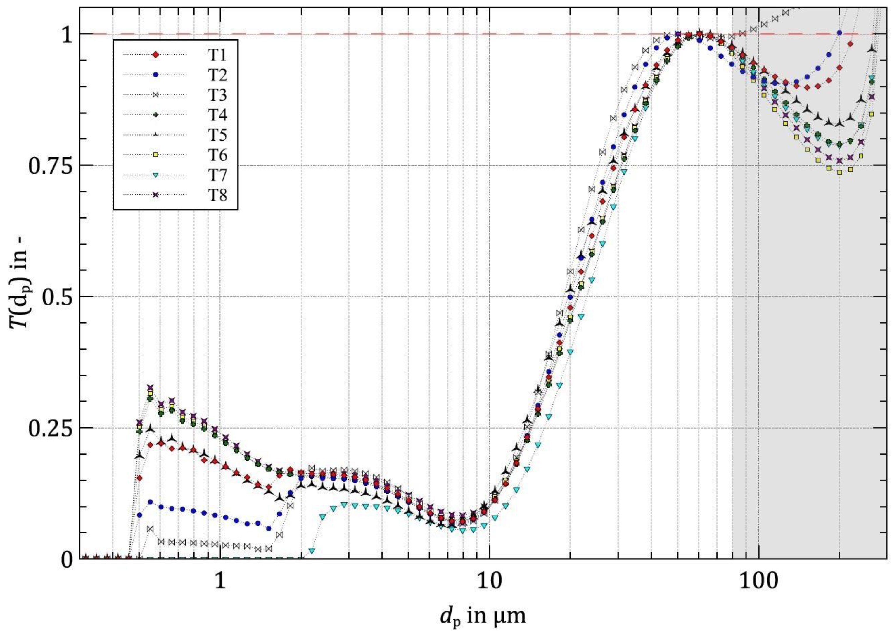
Figure 11 depicts the fractional efficiency with a flow rate of 57.5 L min−1. The cut particle sizes of the test cyclones fall within a narrow range, approximately between 21 and 23 μm. Even in fractional efficiency, the cyclone models show minimal differences at this flow rate setting. The fractional efficiency curves exhibit a more pronounced fishhook effect. This indicates that, due to turbulences in the cone, even the finest particles are dispersed in the underflow region. Consequently, in the current distribution ratio of discharge flows, the evenly distributed particles exit the separation apparatus [1].
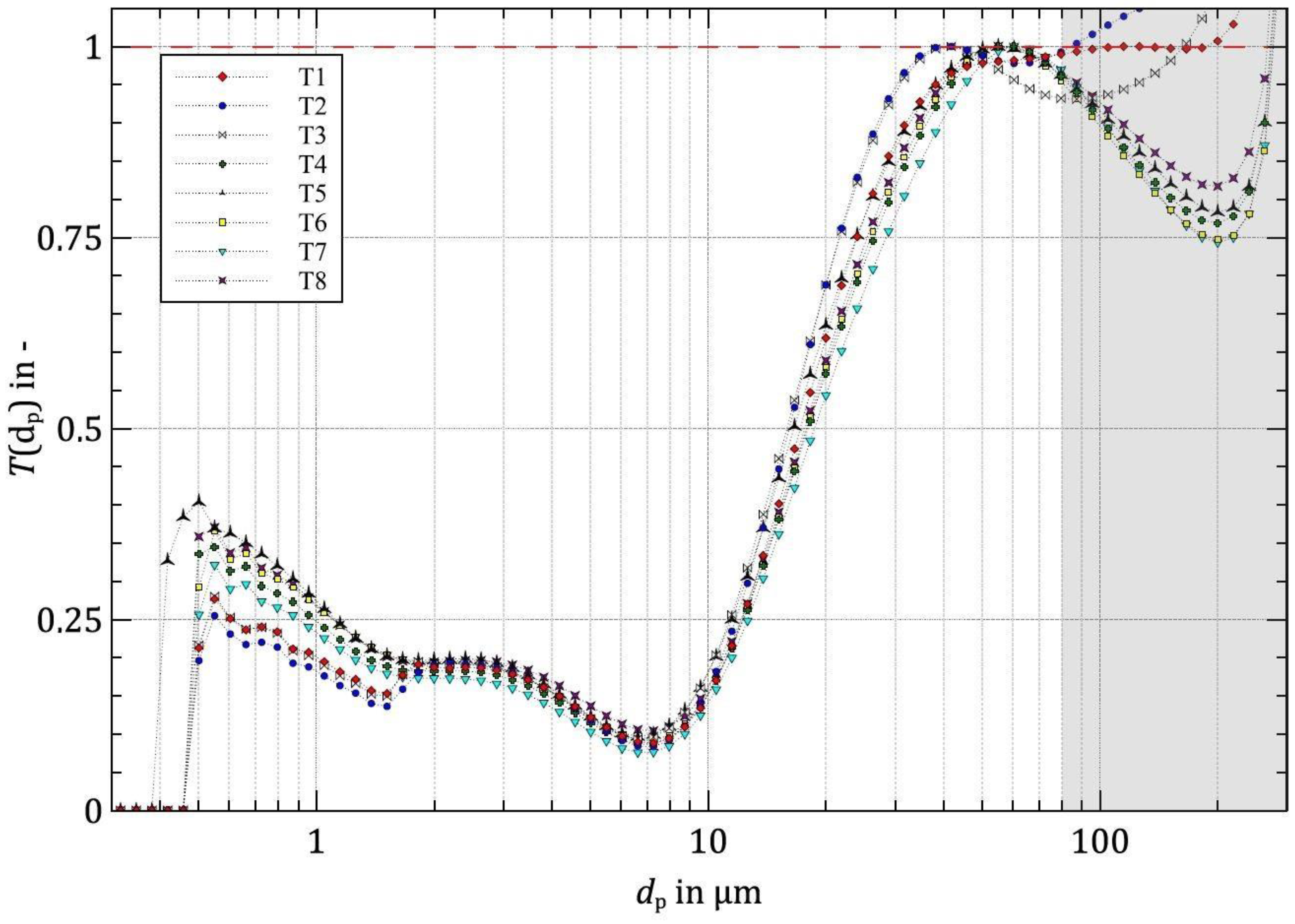
With a volume flow rate of 75 L min−1, the smallest cut particle diameters were achieved, ranging between approximately 17 and 19 μm. The fractional efficiency curves become increasingly similar. Additionally, in Figure 12, it is evident that half of the test cyclones discharge particles < 1 μm with over a 25% probability as part of the coarse fraction.
At volume flow rates of 40 L min−1 and 57.5 L min−1, differences in classification behavior are noticeable, especially in the formation of the re-rise of the separation curve in the fine particle range. The indicative parameter for classification sharpness κ according to Eder approaches values of approximately 0.5 (Equation (9)) in the experiment. Hence, the separation process lies within the range of technical classification [14]. The particle diameters derived from the fractional efficiency curve at the ordinates 0.25 and 0.75 correspond to the diameters d 25 and d 75 .
κ = d 25 d 75

4. Discussion

A predominantly linear increase in separation efficiency is observed with increasing flow rates, suggesting the potential capacity for further efficiency at higher flow rates (Figure 9). For cyclone Types 5 (curved design) and 6 (cylindrical design), a less pronounced increase in separation efficiency is noticeable between 57.5 L min−1 and 75 L min−1, implying that further increases in feed flow might not necessarily improve separation. Types 1 and 2, both with a conical design, achieved nearly identical separation efficiencies compared to the Rietema design. However, the pressure loss exhibited differences. On average, the Rietema cone generated approximately 12% lower pressure loss at 40 L min−1 and about 8% less at 75 L min−1 compared to the conical models. The discrepancy in pressure loss between these designs with the same separation efficiency and cone shape might be related to the differing manufacturing materials. Glass has a smoother surface than PVC, which might lead to more turbulent conditions and intercellular vortices on the rougher PVC surface, potentially reducing friction against the cyclone wall. At the lowest flow rate of 40 L min−1, both curved and cylindrical models demonstrate nearly identical separation efficiencies, with this group exhibiting, on average, a 4% lower separation efficiency compared to conical shapes. At the medium flow rate of 57.5 L min−1, differences in separation performance among the cone shapes are minimal. However, at the highest flow rate of 75 L min−1, Types 1, 2, and 8 with conical shapes again achieve the highest separation efficiencies. Only Type 3 with a curved design nearly matched this high separation efficiency, while noticeable drops were observed in all other non-cylindrical models (Types 4, 5, 6, and 7) achieving approximately 2.5% lower separation rates. Regarding pressure loss, all bottle-based cones exhibit approximately 8400 Pa at the smallest flow rate of 40 L min−1. For higher volume flows of 57.5 L min−1 and 75 L min−1, differences between the experimental cones become more apparent. Type 5 with a curved cone design demonstrated poor results when comparing the pressure loss to separation efficiency (Δpv/η), generating a relatively high pressure loss with lower separation efficiency. In contrast, Type 1 and Type 8 with the simple conventional cone design achieve high separation efficiency with less pressure loss. During the experiments, no notable differences between the cyclone types were observed through optical observations. In all experimental cyclones, a nearly equal-sized air core formed around the axis of rotation. At 40 L min−1, although only a cone-shaped air core formed, it extended to the underflow nozzle. At 75 L min−1, all models formed a uniformly cylindrical air core extending to the underflow nozzle. The remaining concentration of the fine section cF is documented in Table 3.
Regarding the cut particle size, no significant differences were observed among the cone types. Unexpectedly, the fractional efficiency of Types 1, 2 (conical design), and 3 (curved design) exhibit unusual behavior in the upper region of the separation curve. The fractional efficiency reaches a 100% probability of being discharged in the underflow only at larger particle diameters. These observations do not align with the determined fractional efficiencies and the mass balance across the system. Types 1, 2, and 3 attain, in some cases, higher fractional efficiency values than other models. Therefore, it is unlikely that this group does not completely separate particles ≳ 80 μm. Moreover, at the lowest volume flow rate, no separation curve reaches the value of T(dp) = 1 at the first peak. Additionally, the fractional efficiency curves exhibit oscillations after the first extremum; ideally, the graphs should demonstrate stable behavior after reaching the ordinate value of 1.
There were observed differences in fractional efficiency; however, they might have been too small to be distinctly identified in the course of determining the fractional efficiency curves. Hence, a clear correlation between the fractional efficiency curves and separation rates could not be established. Nevertheless, the fractional efficiency curves in the diagrams exhibit distinct classification forms. To obtain the correct fractional efficiency curves, some of the separation rates had to be increased by a factor of ≈1.3 to adjust the separation functions to a value of 1. Consequently, it is assumed that this is not caused by an error in the fractional efficiency because although this factor in the fractional efficiency function generates an offset effect, it would require more significant deviations to be statistically significant. Rather, the irregularity is attributed to the measurement of coarse particles.
In addition to these findings, a comparison was made with previously conducted experiments involving modified cone geometries by Yang and Qiang [16]. Yang obtained slightly altered results with a cone composed of different angle combinations. In comparison to the standard design, the modified cone had minimal impact on particle size during separation. However, the newly designed cone achieved improved separation for small particle sizes, leading to a decline in classification efficiency. Moreover, a higher pressure drop was noted compared to the conventional model. A similar behavior was observed in some of the cyclones used in the experiments, including Type 8 with the Rietema-based standard cone. Type 6 with a cylindrical cyclone model exhibited a nearly identical fractional efficiency curve. The bulbous taper at the underflow suggested that fine particles transported into the lower section of the separation chamber were not remixed. The subsequent expansion before the underflow opening could act as a separate chamber. Jiang utilized a cone with a curved design, similar to the presented cyclones Type 3, 4, and 5 which also offer a curved cone design. This design demonstrated larger particle sizes and a sharper separation. However, no correspondence was found concerning the experiments with the curved cones. This discrepancy might stem from differences in suspension loading or from potential methodological errors. Ghodrat conducted a numerical analysis, comparing a concave and a convex cone with the original design [17]. The convex design in the simulation led to a relatively lower pressure loss and a smaller bypass effect. Yet, clear relationships for these performance parameters were not determined in this study.

5. Conclusions

This study demonstrated that HCs constructed from beverage bottles match conventional cyclone designs in separation efficiency and particle handling. Conical bottles showed similar and even enhanced separation performance compared to traditional cyclones, especially at higher volume flows. With Type 1 and Type 2, which employ a simple conical design, competitive separation efficiencies of 78.5% and 78.4% were achieved compared to 78.0% with the state-of-the-art Rietema design when operating at 75 L min−1. However, differences surfaced in separation efficiency among experimental cyclones, notably when comparing pressure loss to separation efficiency. Certain models experienced reduced efficiency despite similar pressure loss values. Types 5 with a curved design and 7 with a cylindrical design, respectively, showed the lowest efficiency at a similar pressure loss ( V ˙ I N   = 75 L min−1). At 57.5 L min−1, minimal differences in efficiency and pressure loss were observed among the experimental cyclones. Conical models had 4% higher efficiency than other cone designs at 40 L min−1. Notable disparities existed between curved and cylindrical shapes using the classical cone design, while clear distinctions between cylindrical and curved forms were absent. Fractional separation sizes of 17–19 μm were achieved at 75 L min−1, with no significant differences observed between cyclone types, although trends in the separation curves varied. Practical implications suggest feasible experimentation at higher flow rates due to the bottles’ resilience. However, reinforcing the connection system between the inlet section and the cone body is advisable to handle increased flow rates. Enlarging the tank volume would enhance experimental reliability. The potential commercial viability of glass bottle HCs, exhibiting comparable separation to standard cyclones, warrants exploration. Glass’s durability against abrasive media suggests its possible everyday use, meriting a long-term durability assessment.

Supplementary Materials

The following supporting information can be downloaded at: https://www.mdpi.com/article/10.3390/separations11080230/s1, Figure S1: Coarse particle size distribution of Types 1–8 hydrocyclones for volume flow rate 40 L min−1 (page 1), 57.5 L min−1 (page 2) and 75.0 L min−1 (page 3).

Author Contributions

Conceptualization, T.S., C.B. and T.K.; methodology, T.S., T.N., C.M., M.B. and M.K.; validation, T.S., C.M., T.K., M.K. and M.B.; formal analysis, M.B., T.N. and M.K.; investigation, T.S., C.B., T.N. and M.B.; resources, T.S., M.P. and M.K.; data curation, C.B., T.N. and M.B.; writing—original draft preparation, T.S., T.N., C.B. and M.B.; writing—review and editing, C.M., T.K., M.K. and M.P.; visualization, C.B., C.M. and M.P.; supervision, M.K. and M.P.; project administration, T.S. and T.K. All authors have read and agreed to the published version of the manuscript.

Funding

This research received no external funding.

Data Availability Statement

The original contributions presented in the study are included in the article/supplementary material, further inquiries can be directed to the corresponding author.

Acknowledgments

The technical support of Muhammed Satik is gratefully acknowledged.

Conflicts of Interest

The authors declare no conflicts of interest.

References

  1. Dallmann, W. Handbuch Der Mechanischen Fest-Flüssig-Trennung; Luckert, K., Ed.; Vulkan-Verlag: Essen, Germany, 2004; ISBN 3-8027-2196-9. [Google Scholar]
  2. Muschelknautz, U. Zyklone zum Abscheiden fester Partikel aus Gasen, VDI Wärmeatlas; Springer: Berlin/Heidelberg, Germany, 2006. [Google Scholar]
  3. Bradley, D. The Hydrocyclone; Pergamon Press: Oxford, UK, 1965. [Google Scholar]
  4. Rietema, K. Performance and Design in Hydrocyclones—III. Chem. Eng. Sci. 1961, 15, 310–319. [Google Scholar] [CrossRef]
  5. Schubert, H. Handbuch Der Mechanischen Verfahrenstechnik, 1st ed.; Schubert, H., Ed.; Wiley-VCH: Weinheim, Germany, 2002; ISBN 978-3-527-30577-3. [Google Scholar]
  6. Gundelach, W.; Trawinski, H.F. Der Hydrozyklon. Ein Einfaches und Billiges Gerät für das Klassieren und Eindicken. Chem.-Ing.-Tech. 1960, 32, 279–284. [Google Scholar] [CrossRef]
  7. Svarovsky, L.; Thew, M.T. Hydrocyclones Analysis and Applications, 1st ed.; Springer Science + Business Media: Dordrecht, The Netherlands, 1992; ISBN 978-94-015-7981-0. [Google Scholar]
  8. Saidi, M.; Maddahian, R.; Farhanieh, B. Numerical Investigation of Cone Angle Effect on the Flow Field and Separation Efficiency of Deoiling Hydrocyclones. Heat Mass Transf. Stoffuebertragung 2013, 49, 247–260. [Google Scholar] [CrossRef]
  9. Senfter, T. Kontinuierliche Störstoffabscheidung in Der Klärschlamm-Co-Fermentation Mittels Zentrifugalabscheider. Ph.D. Thesis, University of Innsbruck, Innsbruck, Austria, 2019. [Google Scholar]
  10. Andritschke, N. Das Aus für Mikroplastik: Mit 1500 g Ins Wirbelzentrum. Wasserwirtsch. Wassertech. 2021, 70, 6–7. [Google Scholar] [CrossRef]
  11. Ji, L.; Paul, P.; Shanbhag, B.K.; Dixon, I.; Kuang, S.; He, L. Emerging Application of Hydrocyclone in Biotechnology and Food Processing. Sep. Purif. Technol. 2023, 309, 122992. [Google Scholar] [CrossRef]
  12. FLSmidth GMAX® Hydrozyklone Feinere Partikeltrennung Mit Patentierter Technologie. FLSmidth 2018. Available online: https://www.flsmidth.com/-/media/brochures/brochures-products/centrifugation-and-classification/2019/krebs-gmax-cyclone_brochure_german.pdf (accessed on 10 May 2024).
  13. Akw, G. Hydrozyklone AKA-VORTEX. Available online: https://de.akwauv.de/hydrozyklone-aka-vortex-2/ (accessed on 10 May 2024).
  14. Stieß, M. Mechanische Verfahrenstechnik—Partikeltechnologie 1, 3rd ed.; Springer: Berlin/Heidelberg, Germany, 2009; ISBN 978-3-540-32551-2. [Google Scholar]
  15. Jiang, L.; Liu, P.; Zhang, Y.; Li, X.; Yang, X.; Xu, H.; Wang, H. Experimental Study of the Separation Performance of a Hydrocyclone with a Compound Curve Cone. Powder Technol. 2022, 409, 117829. [Google Scholar] [CrossRef]
  16. Yang, Q.; Wang, H.; Liu, Y.; Li, Z. Solid/Liquid Separation Performance of Hydrocyclones with Different Cone Combinations. Sep. Purif. Technol. 2010, 74, 271–279. [Google Scholar] [CrossRef]
  17. Ghodrat, M.; Kuang, S.B.; Yu, A.B.; Vince, A.; Barnett, G.D.; Barnett, P.J. Numerical Analysis of Hydrocyclones with Different Conical Section Designs. Miner. Eng. 2014, 62, 74–84. [Google Scholar] [CrossRef]
  18. Vimal, A.; Thalaieswaran, S.; Kannan, N.H.; Ganeshan, P.; Venkatesh, S. A Review on the Investigation of Hydrocyclone Performance by Shape Optimization. In E3S Web of Conferences; EDP Sciences: Les Ulis, France, 2023; Volume 405. [Google Scholar] [CrossRef]
  19. Ni, L.; Tian, J.; Song, T.; Jong, Y.; Zhao, J. Optimizing Geometric Parameters in Hydrocyclones for Enhanced Separations: A Review and Perspective. Sep. Purif. Rev. 2019, 48, 30–51. [Google Scholar] [CrossRef]
  20. Yoshida, H.; Takashina, T.; Fukui, K.; Iwanaga, T. Effect of Inlet Shape and Slurry Temperature on the Classification Performance of Hydro-Cyclones. Powder Technol. 2004, 140, 1–9. [Google Scholar] [CrossRef]
  21. Zhang, C.; Wei, D.; Cui, B.; Li, T.; Luo, N. Effects of Curvature Radius on Separation Behaviors of the Hydrocyclone with a Tangent-Circle Inlet. Powder Technol. 2017, 305, 156–165. [Google Scholar] [CrossRef]
  22. Chlebnikovas, A.; Jasevičius, R. Investigation of the Interaction of Particulate Matter and Its Separation from the Gas Flow in a Multi-Channel Cyclone with Recirculation. Granul. Matter 2022, 24, 98. [Google Scholar] [CrossRef]
  23. Raimondas Jasevičius Pranas Baltrėnas, R.K.; Grubliauskas, R. DEM Simulation of the Impact of Ultrafine Glass Particles on the Partition Wall of the Multichannel Cyclone. Part. Sci. Technol. 2014, 32, 576–587. [Google Scholar] [CrossRef]
  24. Chlebnikovas, A.; Paliulis, D.; Kilikevičienė, K.; Kilikevičius, A. Experimental Research of Gaseous Emissions Impact on the Performance of New-Design Cylindrical Multi-Channel Cyclone with Adjustable Half-Rings. Sustainability 2022, 14, 902. [Google Scholar] [CrossRef]
  25. Zhou, Y.; Zhong, S.; Li, L. Characteristics and Mechanisms of Particle Adhesion Patterns in an Aerodynamic Cyclone. Aerosol Sci. Technol. 2017, 51, 1313–1323. [Google Scholar] [CrossRef]
  26. Zhou, Y.; See, T.; Zhong, S.; Liu, Z.; Li, L. A Massive Reduction of Dust Particle Adhesion in a Cyclone by the Introduction of a Wedge. Proc. Inst. Mech. Eng. Part C J. Mech. Eng. Sci. 2017, 232, 3102–3114. [Google Scholar] [CrossRef]
  27. Zhou, Y.; See, T.; Zhong, S.; Liu, Z.; Li, L. A 2D Mesh-Free Simulation of the Particle Adhesion in a Plastic Cyclone. Proc. Inst. Mech. Eng. Part C J. Mech. Eng. Sci. 2018, 233, 095440621875879. [Google Scholar] [CrossRef]
  28. Rietema, K. Performance and Design of Hydrocyclones-IV Design of Hydrocyclones. Chem. Eng. Sci. 1961, 15, 320–825. [Google Scholar] [CrossRef]
  29. Bonfig, K.W. Taschenbuch Der Messtechnik, 7th ed.; Jörg, H., Ed.; Carl Hanser Verlag: Munich, Germany, 2015; ISBN 978-3-446-44271-9. [Google Scholar]
  30. Neeße, T.; Schubert, H.; Graichen, K. Praktische und Theoretische Aspekte Der Dichtstromklassierung. Aufb.-Technol. 1991, 32, 459–472. [Google Scholar]
  31. Trawinski, H.F. Practical Aaspects of the Design and Industrial Applications of the Hydrocyclone. Filtr. Sep. 1969, 6, 361–367. [Google Scholar]
  32. Hemming, W. Verfahrenstechnik, 8th ed.; Vogel Buchverlag: Landsberg, Germany, 1999; ISBN 3-8023-1774-2. [Google Scholar]
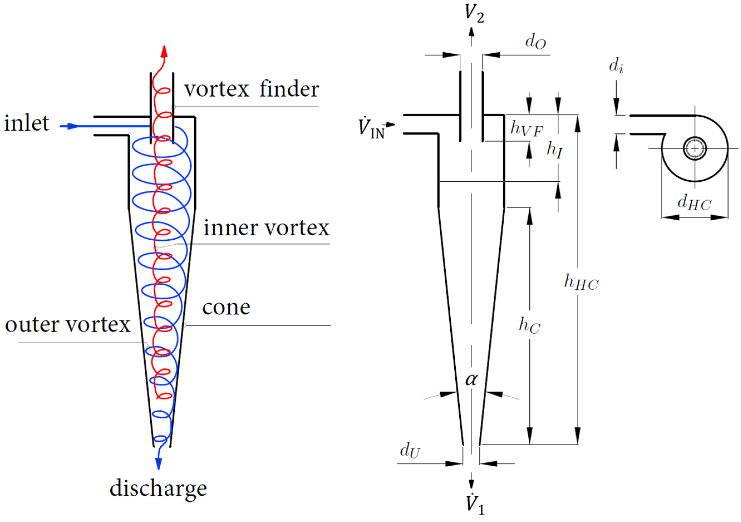
Figure 1. Illustration of a basic counterflow HC with relevant geometric variables. Blue line indicates the primary vortex in downward direction, and red line indicates the secondary vortex in an upward direction.
Separations 11 00230 g001
Figure 2. (a) Illustration of the piping and instrumentation (P&ID) of and (b) the test rig for the experimental separation evaluation. Variable flow rate of pump P1 (5.3 m3 h−1 at 55 m head) is set at 40.0 L min−1, 57.5 L min−1 and 75.0 L min−1 for three experimental runs, respectively. Moreover, 0.075 kg Carolith 0–0.2 is solved in 30 L water in vessel B1. Pressure indicators (PIs) and temperature indicators (TIs) are installed accordingly.
Separations 11 00230 g002
Figure 3. Characteristic shapes of the used separation chambers based on upcycled glass bottles. Volume and geometric information is documented in Table 1.
Separations 11 00230 g003
Figure 4. Connection systems (welded (A), clamped joint (B) and hose clamp (C)) to join the inlet section to the cyclone cone (glass bottles or Rietema cone).
Separations 11 00230 g004
Figure 5. Illustration of Type 8 separation chamber with relevant dimensions and inlet section used for all HCs. Both apparatuses’ dimensions are derived from the Rietema design and are displayed in mm.
Separations 11 00230 g005
Figure 6. Three-dimensional model of the Rietema cyclone used for comparison of the bottle-based cyclones.
Separations 11 00230 g006
Figure 7. Schematic illustration of the experimental procedure.
Separations 11 00230 g007
Figure 8. Particle size analyses of the inlet feed (Carolith 0–0.2) using Mastersizer 2000. Ten repetitions are used for generation of mean values.
Separations 11 00230 g008
Figure 9. Separation efficiency η and pressure drop Δpv from the experiments are represented by the data points, which indicate the mean values. The error bars denote the maximum and minimum measured values.
Separations 11 00230 g009
Figure 10. Fractional efficiency T(dp) of all HCs at a flow rate setting of 40 L min−1 of the coarse section extracted from the underflow discharge using Carolith 0–0.2.
Separations 11 00230 g010
Figure 11. Fractional efficiency T(dp) of all HCs at a flow rate setting of 57.5 L min−1 of the coarse section extracted from the underflow discharge using Carolith 0–0.2.
Separations 11 00230 g011
Figure 12. Fractional efficiency T(dp) of all HCs at a flow rate setting of 75 L min−1 of the coarse section extracted from the underflow discharge using Carolith 0–0.2.
Separations 11 00230 g012
Table 1. Geometric information of the HC based on upcycled glass bottles (Type 1–Type 7) and on the HC based on the Rietema design (Type 8).
Bottle TypeShape Diameter   d H C Length   h H C Volume
--mmmmmL
Type 1Conical69315747
Type 2Conical77255737
Type 3Curved72286722
Type 4Curved74275761
Type 5Curved72271758
Type 6Cylindrical71281751
Type 7Cylindrical71254757
Type 8Rietema73320750
Table 2. Geometric information of cyclone models based on designs of Rietema and Bradley [3,4,28].
Cyclone Model h H C d H C d O d H C d i d H C h V F d H C h H C     h C d H C
Rietema50.280.340.40-
Bradley-0.140.200.330.5
Table 3. Detailed data of all experimental runs displayed the matrix in Figure 9. The inlet concentration, cI, is set at 2.5 g L−1.
Type V ˙ I N V ˙ U V ˙ U V ˙ O Δ p v ηcF
-L min−1L min−1%bar%g L−1
Type 140.0
57.5
75.0
0.44
0.61
0.77
1.12
1.08
1.03
0.086
0.182
0.320
64.0
71.0
78.5
0.90
0.73
0.54
Type 240.0
57.5
75.0
0.36
0.53
0.69
0.92
0.94
0.93
0.088
0.186
0.334
64.2
70.9
78.4
0.90
0.73
0.54
Type 340.0
57.5
75.0
0.40
0.59
0.75
1.00
1.03
1.01
0.080
0.198
0.330
62.4
70.4
77.9
0.94
0.74
0.55
Type 440.0
57.5
75.0
0.39
0.57
0.73
0.98
1.00
0.98
0.082
0.192
0.322
62.2
70.2
76.6
0.95
0.75
0.59
Type 540.0
57.5
75.0
0.37
0.58
0.74
0.92
1.03
1.00
0.090
0.190
0.356
59.9
71.9
76.4
1.00
0.70
0.59
Type 640.0
57.5
75.0
0.44
0.63
0.78
1.12
1.10
1.05
0.082
0.184
0.326
61.7
70.5
76.5
0.96
0.74
0.59
Type 740.0
57.5
75.0
0.38
0.56
0.72
0.95
0.98
0.96
0.082
0.182
0.336
62.4
69.1
75.5
0.94
0.77
0.61
Type 840.0
57.5
75.0
0.53
0.69
0.83
1.30
1.21
1.12
0.074
0.178
0.304
65.4
71.3
78.0
0.87
0.72
0.55
Disclaimer/Publisher’s Note: The statements, opinions and data contained in all publications are solely those of the individual author(s) and contributor(s) and not of MDPI and/or the editor(s). MDPI and/or the editor(s) disclaim responsibility for any injury to people or property resulting from any ideas, methods, instructions or products referred to in the content.