
Optimization Design of Centrifugal Pump Flow Control System Based on Adaptive Control


Abstract
:1. Introduction
2. Modeling of Centrifugal Pump Flow Control System
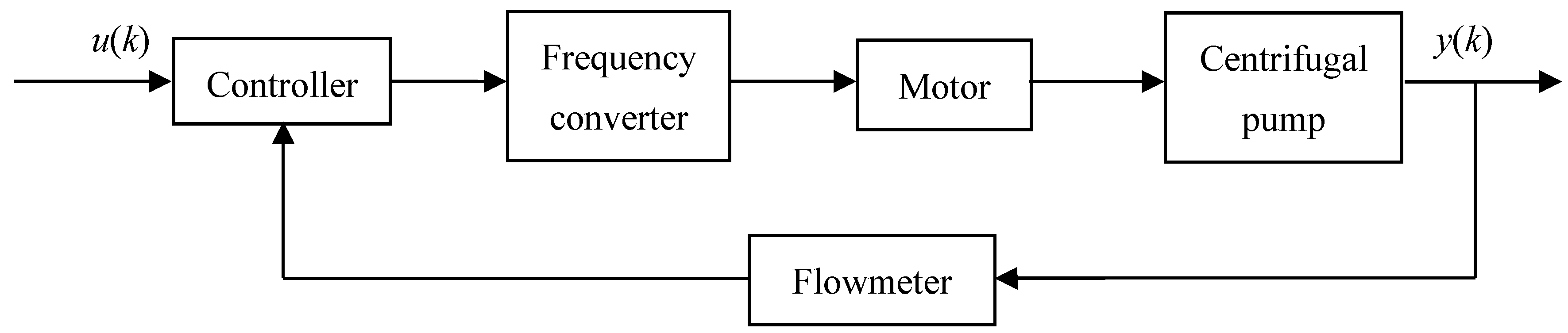
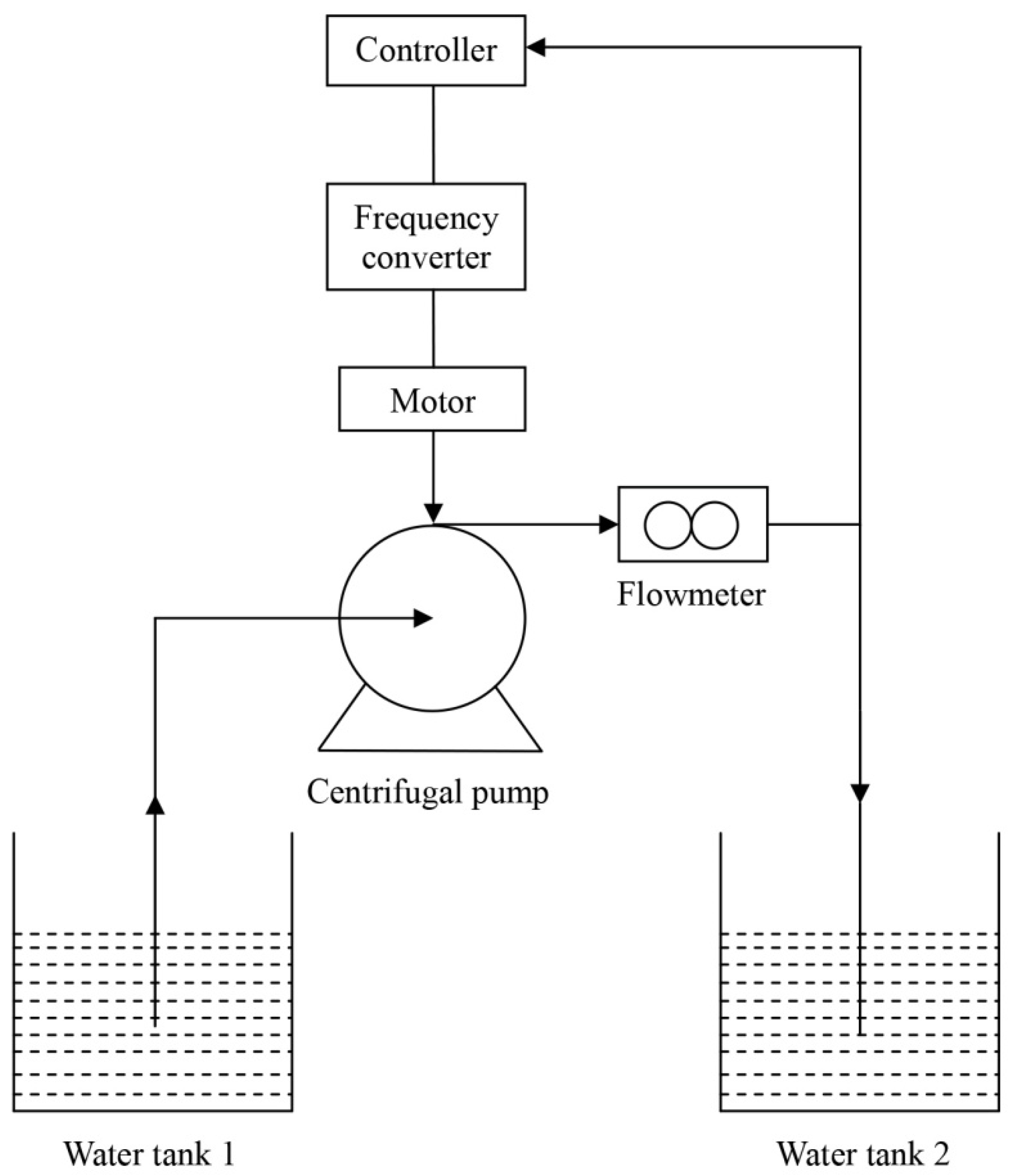
2.1. Structure Design
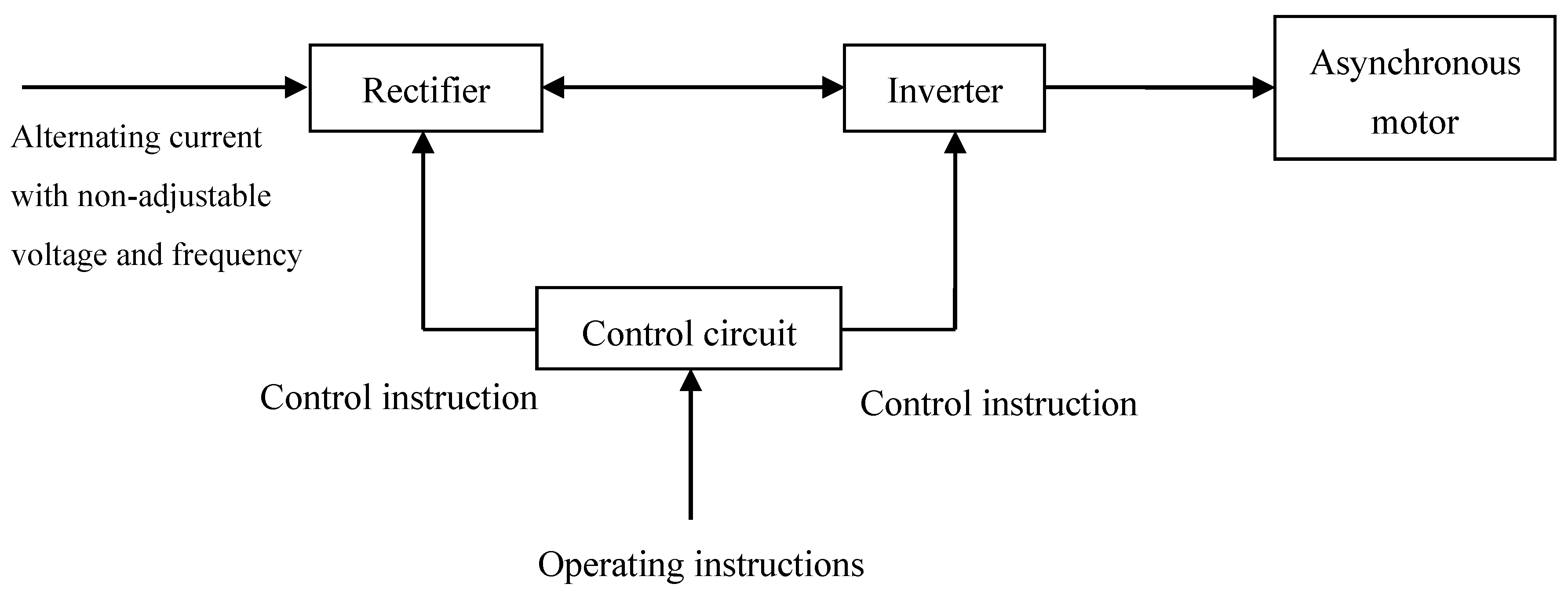
2.2. Frequency Converter Mathematical Model
2.3. Motor Mathematical Model
2.4. Centrifugal Pump Mathematical Model
- (1)
- The pulsation of the centrifugal pump is ignored;
- (2)
- The leakage state of the centrifugal pump is laminar flow;
- (3)
- The dynamic process of the centrifugal pump is neglected.
2.5. Control System Mathematical Model
3. Flow Adaptive Control Method for Centrifugal Pump
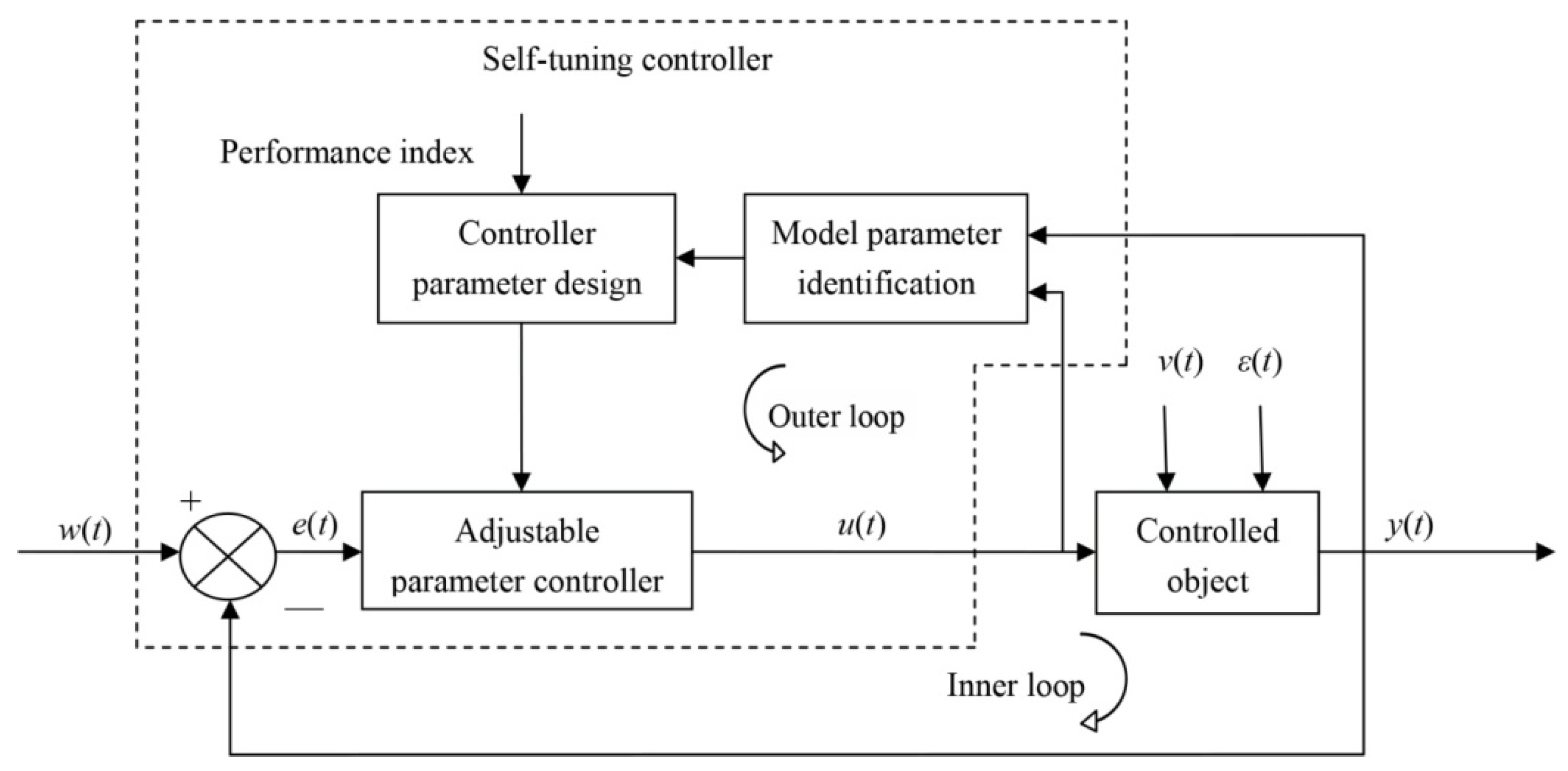
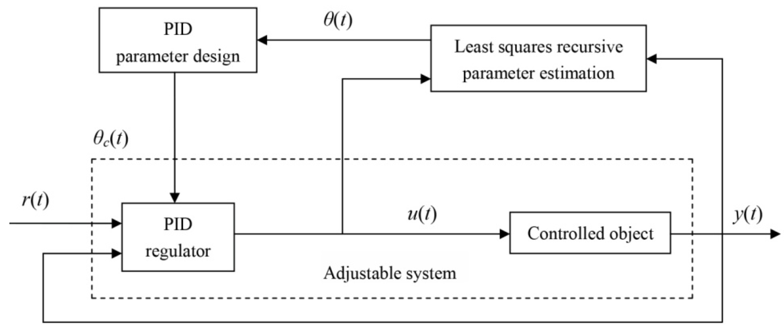
3.1. Control Scheme
3.2. Description of Controlled Object Model
3.3. Real-time Parameter Estimation Algorithm
4. System Simulation and Analysis
4.1. Parameter Determination
- (1)
- The initial data is inputted, and the initial values , and the forgetting factor are set;
- (2)
- The current actual output of the acquisition system is ;
- (3)
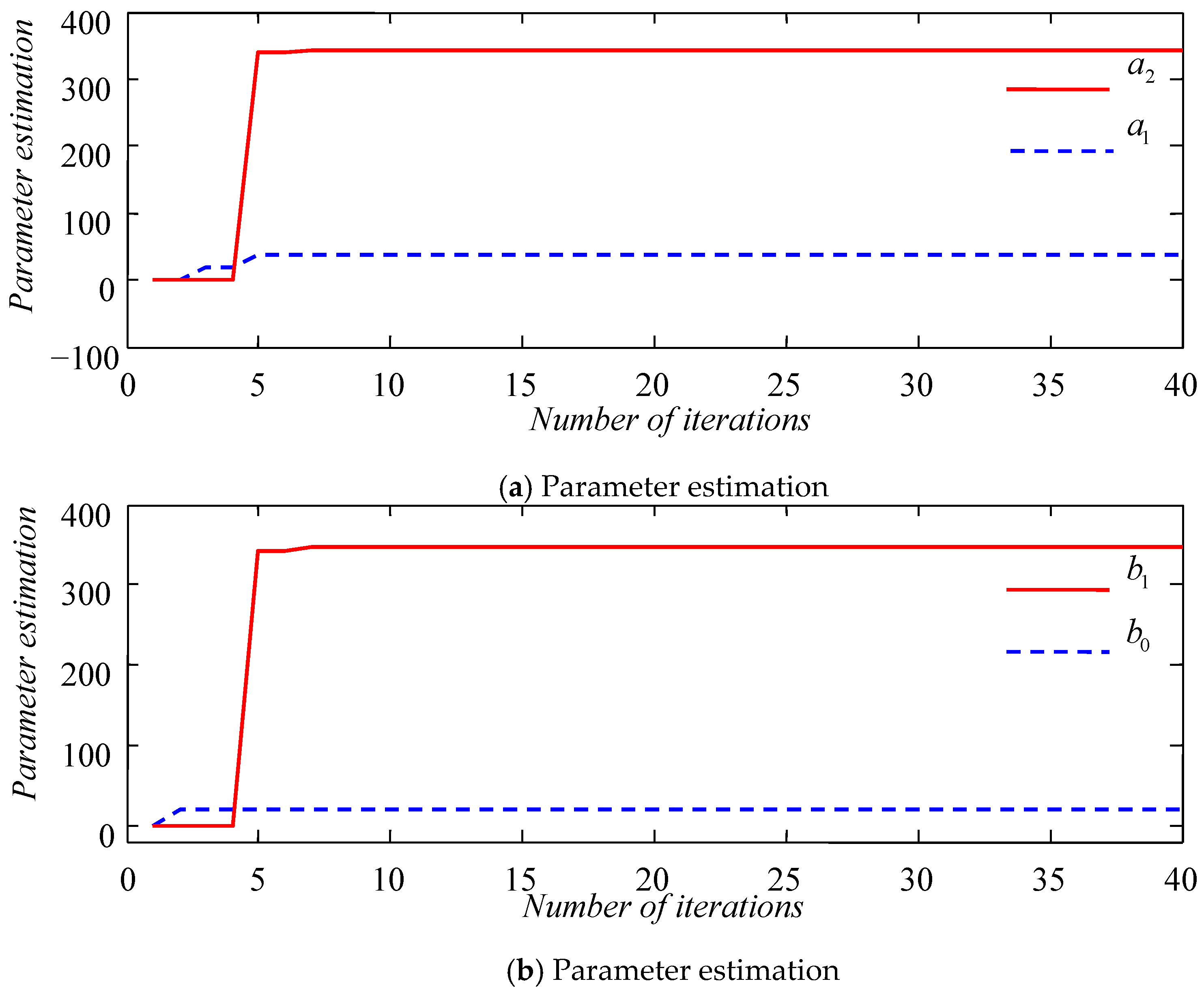
- The real-time parameter of the control target is estimated by the recursive least squares method with the forgetting factor through model parameter identification;
- (4)
- Solving and in Equation (20), taking and ;
- (5)
- Calculate the control quantity and regulate the system through Equation (19);
- (6)
- Return to step (2) and continue the loop .
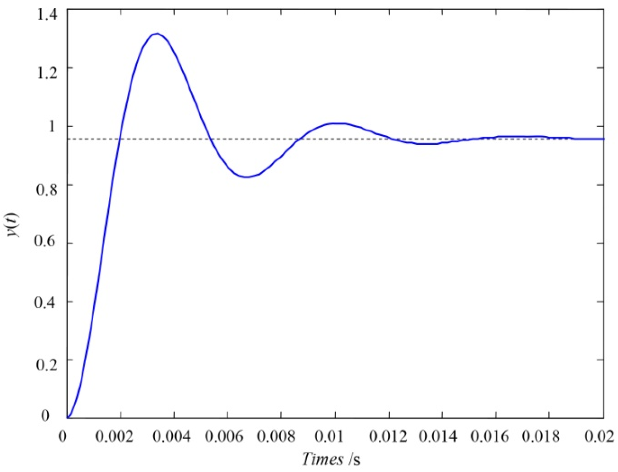
4.2. System Simulation and Analysis
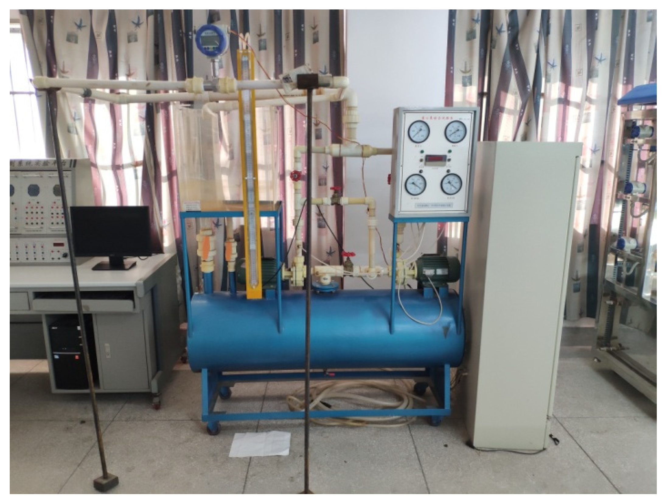
5. Experimental Analysis of Centrifugal Pump Flow Adaptive Control System
5.1. Test Platform Construction
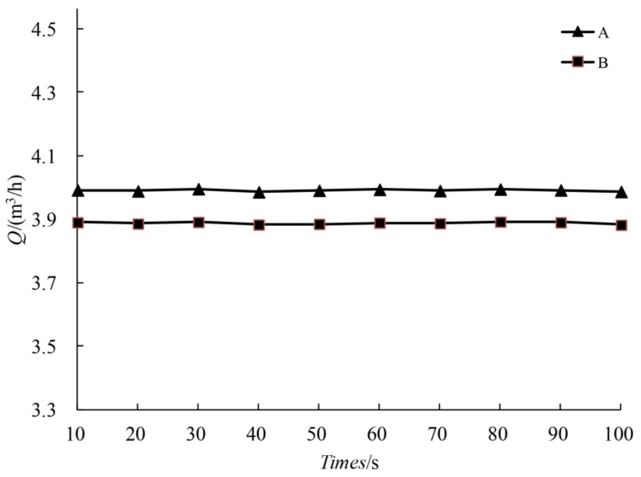
5.2. Data Acquisition and Analysis of Constant Frequency Flow
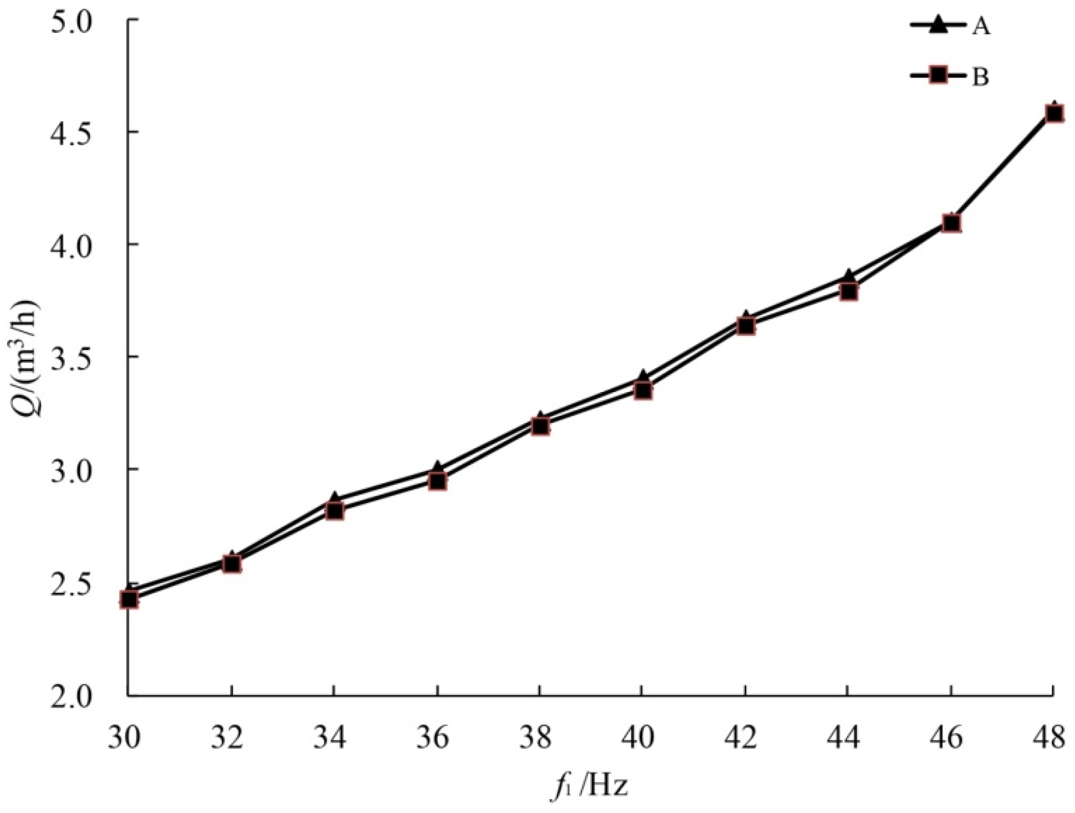
5.3. Data Acquisition and Analysis of Variable Frequency Flow
6. Conclusions
- (1)
- By analyzing the components of a frequency converter, motor, and centrifugal pump, the frequency converter and centrifugal pump were simplified as a proportional link. The motor was simplified as an electrical link connected in a series with a mechanical link, and the mathematical model of the centrifugal pump adaptive control system was established.
- (2)
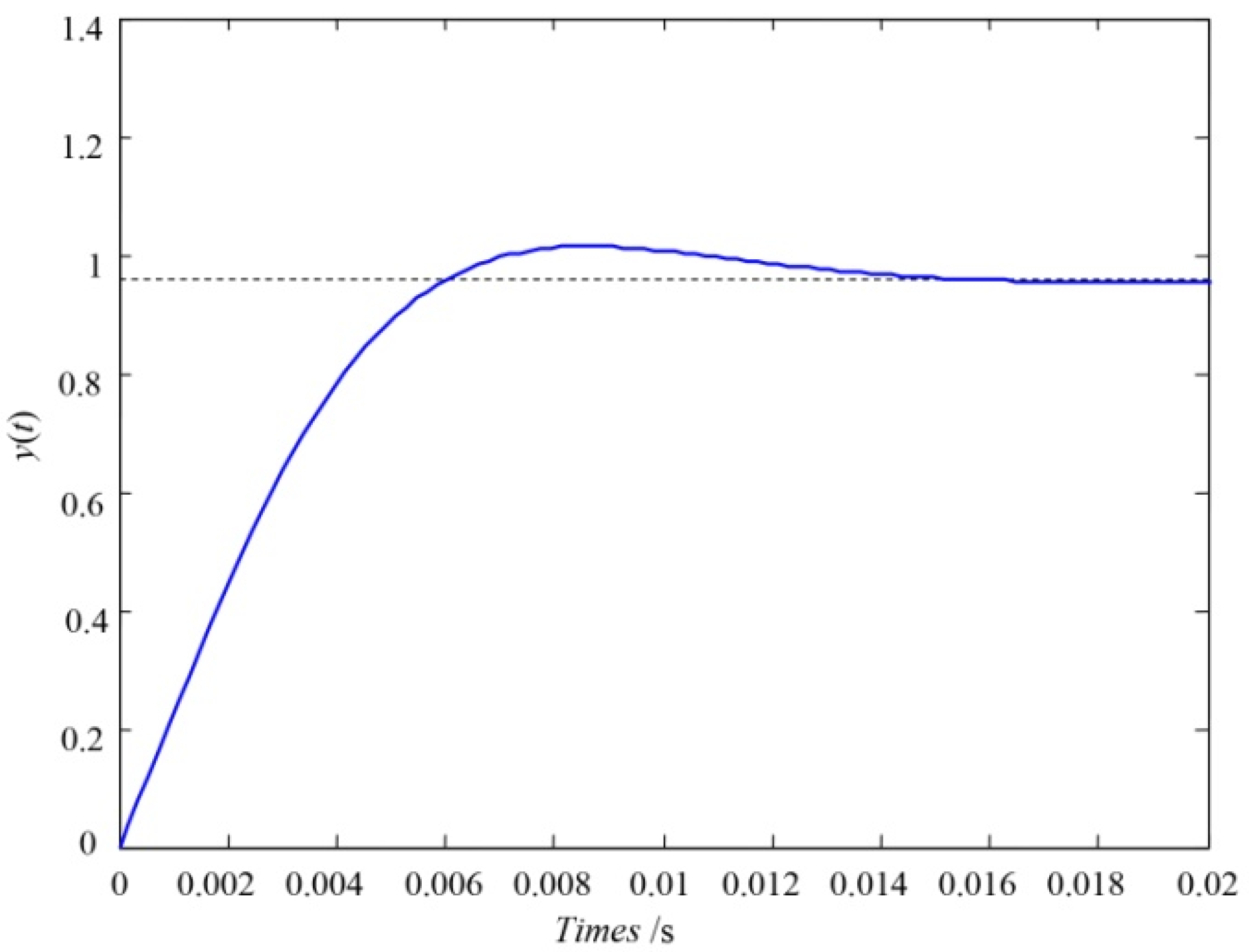
- A self-tuning PID controller based on the adaptive control method was constructed, a discrete-time stochastic linear model was used to describe the controlled object model, and the forgetting factor recursive least squares method was used to estimate the parameters in real-time. The simulation results showed that the dynamic characteristics of the optimized system were significantly improved, and the rapidity and stability of the transient response of the system were both improved.
- (3)
- The test platform was built based on the NGL002 centrifugal pump comprehensive test device, and a good control effect was obtained. After optimization, the centrifugal pump flow control system had strong robustness and had better real-time followability. The accuracy of the self-tuning PID control algorithm was further verified.
- (4)
- In order to improve the robustness and stability of the centrifugal pump, the mathematical model of the control system was obtained on the basis of deducing the mathematical model of the frequency converter, motor and centrifugal pump. The adaptive control algorithm was used to optimize the design of the system. The least squares recursive algorithm was used to estimate the parameters, and the self-tuning PID controller was added to adjust the parameters of the centrifugal pump control system. The experimental results showed that the optimized centrifugal pump control system shortened the adjustment time, reduced the maximum overshoot, and the system’s rapidity and stability were significantly improved. Based on the test platform of the centrifugal pump flow adaptive control system, the flow data of a fixed frequency and variable frequency were collected. The collected data showed that the error between the actual flow curve and the theoretical flow curve of the pump was small, which verified the accuracy of the self-tuning PID control algorithm. It could be seen that based on the adaptive control algorithm, the performance of each index of the centrifugal pump flow control system could be improved, and the stability and robustness of the system could also be improved. This has certain guiding significance for the ability of centrifugal pumps to effectively cope with various complicated working conditions and to improve work efficiency during the operation process.
Author Contributions
Funding
Institutional Review Board Statement
Informed Consent Statement
Data Availability Statement
Conflicts of Interest
References
- Wang, X.; Kuang, K.; Wu, Z.; Yang, J. Numerical simulation of axial vortex in a centrifugal pump as turbine with S-blade impeller. Processes 2020, 8, 1192. [Google Scholar] [CrossRef]
- Gülich, J.F. Centrifugal Pumps; Springer: Heidelberg, Germany, 2010. [Google Scholar]
- Lobanoff, V.S.; Ross, R.R. Centrifugal Pumps: Design and Application; Gulf Publishing Company: Houston, TX, USA, 1992. [Google Scholar]
- Gevorkov, L.; Rassõlkin, A.; Kallaste, A.; Vaimann, T. Simulink based model for flow control of a centrifugal pumping system. In Proceedings of the International Workshop on Electric Drives: Optimization in Control of Electric Drives, Moscow, Russia, 31 January–2 February 2018; pp. 1–4. [Google Scholar]
- Suh, S.H.; Kim, K.W.; Kim, H.H.; Yoon, I.S.; Cho, M.T. A Study on energy saving rate for variable speed condition of multistage centrifugal pump. J. Therm. Sci. 2015, 24, 566–573. [Google Scholar] [CrossRef]
- Mingxin, C.; Lingfeng, T.; Jian, H. Research on flow control system of pump based on fuzzy PID. J. Xinxiang Univ. 2014, 31, 36–40. (in Chinese). [Google Scholar]
- Lu, J.; Chen, M. Reach on the H∞ control system of the centrifugal pumps. J. Tongren Univ. 2018, 20, 68–75. (in Chinese). [Google Scholar]
- Xie, S.; Chai, T. A kind of fuzzy PID controller with parameter adaption. Inf. Control. 1998, 27, 255–259. (in Chinese). [Google Scholar]
- Perissinotto, R.M.; Verde, W.M.; Perles, C.E.; Biazussi, J.L.; de Castro, M.S.; Bannwart, A.C. Experimental analysis on the behavior of water drops dispersed in oil within a centrifugal pump impeller. Exp. Therm. Fluid Sci. 2019, 112, 1–18. [Google Scholar] [CrossRef]
- Hu, J. Research of Wet Desulfurization Dust Control System. Master’s Thesis, Anhui Polytechnic University, Wuhu, China, 2014. (in Chinese). [Google Scholar]
- Gang, C. The Research of The Method on The Frequency Conversion Energy-Conservation of the Hydraulic Apparatus Controls. Master’s Thesis, Guizhou University, Guiyang, China, 2010. (in Chinese). [Google Scholar]
- Zeng, G.; Qian, M. Frequency conversion driving technology of AC asynchronous motor. Electr. Abstr. 2014, 5, 13–17. (in Chinese). [Google Scholar]
- Jun, W. Research on low frequency torque insufficiency of frequency converter. China Sci. Technol. Inf. 2015, 2, 183–184. (in Chinese). [Google Scholar]
- Zhao, X.S.; Hu, J.; Shi, P.C. Hydromechanics research of pump flow control system based on BP neural network PID. Appl. Mech. Mater. 2013, 327, 222–226. [Google Scholar] [CrossRef]
- Wen, M. Analysis of flow adjustment method of centrifugal pump. China Pet. Chem. Stand. Qual. 2012, z2, 117. (in Chinese). [Google Scholar]
- Jiang, J.; Zhang, Y. A revisit to block and recursive least squares for parameter estimation. Comput. Electr. Eng. 2004, 30, 403–416. [Google Scholar] [CrossRef]
- Ding, F.; Wang, X.; Chen, Q.; Xiao, Y. Recursive least squares parameter estimation for a class of output nonlinear systems based on the model decomposition. Circuits Syst. Signal Process. 2016, 35, 3323–3338. [Google Scholar] [CrossRef]
- Alexandrov, A.; Palenov, M. Self-tuning PID-I controller. Autom. Remote Control 2011, 44, 3635–3640. [Google Scholar] [CrossRef] [Green Version]
- Makarem, S.; Delibas, B.; Koc, B. Data-driven tuning of PID controlled piezoelectric ultrasonic motor. Actuators 2021, 10, 148. [Google Scholar] [CrossRef]
- Xie, X.; Ding, F. Adaptive Control System; Tsinghua University Press: Beijing, China, 2002. (in Chinese) [Google Scholar]
- Paleologu, C.; Benesty, J.; Ciochina, S. A robust variable forgetting factor recursive least-squares algorithm for system identification. IEEE Signal Process. Lett. 2008, 15, 597–600. [Google Scholar] [CrossRef]
- Pang, Z.; Cui, H. System Identification and Adaptive Control Matlab Simulation; Beihang University Press: Beijing, China, 2013. (in Chinese) [Google Scholar]
- Luo, H.; Mao, Y.; Zhang, J. Design and simulation of a parameter adaptive fuzzy PID controller. Autom. Instrum. 2001, 3, 10–12. (in Chinese). [Google Scholar]
- Hu, M.; Feng, J.; Zheng, J. An additional branch free algebraic B-spline curve fitting method. Vis. Comput. 2010, 26, 801–811. [Google Scholar] [CrossRef]


| Transient Response Index | Original System | Optimized System | Performance Change (%) |
|---|---|---|---|
| Rise time/s | 0.00135 | 0.00425 | −214.81 |
| Peak time/s | 0.0033 | 0.0067 | −103.03 |
| Adjusting time/s | 0.0187 | 0.0156 | 16.58 |
| Maximum overshoot | 0.3752 | 0.0604 | 83.90 |
| Error Rate (%) | |||
|---|---|---|---|
| 10 | 3.954 | 3.852 | 2.580 |
| 20 | 3.951 | 3.848 | 2.607 |
| 30 | 3.958 | 3.853 | 2.653 |
| 40 | 3.948 | 3.845 | 2.609 |
| 50 | 3.953 | 3.847 | 2.682 |
| 60 | 3.956 | 3.851 | 2.654 |
| 70 | 3.952 | 3.849 | 2.606 |
| 80 | 3.957 | 3.854 | 2.603 |
| 90 | 3.954 | 3.852 | 2.580 |
| 100 | 3.949 | 3.844 | 2.659 |
| Error Rate (%) | |||
|---|---|---|---|
| 30 | 2.458 | 2.428 | 1.221 |
| 32 | 2.603 | 2.586 | 0.653 |
| 34 | 2.865 | 2.822 | 1.501 |
| 36 | 3.002 | 2.954 | 1.599 |
| 38 | 3.223 | 3.198 | 0.776 |
| 40 | 3.408 | 3.357 | 1.496 |
| 42 | 3.672 | 3.644 | 0.763 |
| 44 | 3.856 | 3.797 | 1.530 |
| 46 | 4.106 | 4.102 | 0.097 |
| 48 | 4.603 | 4.589 | 0.304 |
Publisher’s Note: MDPI stays neutral with regard to jurisdictional claims in published maps and institutional affiliations. |
© 2021 by the authors. Licensee MDPI, Basel, Switzerland. This article is an open access article distributed under the terms and conditions of the Creative Commons Attribution (CC BY) license (https://creativecommons.org/licenses/by/4.0/).
Share and Cite
Wang, Y.; Zhang, H.; Han, Z.; Ni, X. Optimization Design of Centrifugal Pump Flow Control System Based on Adaptive Control. Processes 2021, 9, 1538. https://doi.org/10.3390/pr9091538
Wang Y, Zhang H, Han Z, Ni X. Optimization Design of Centrifugal Pump Flow Control System Based on Adaptive Control. Processes. 2021; 9(9):1538. https://doi.org/10.3390/pr9091538
Chicago/Turabian StyleWang, Yuqin, Haodong Zhang, Zhibo Han, and Xiaoqiang Ni. 2021. "Optimization Design of Centrifugal Pump Flow Control System Based on Adaptive Control" Processes 9, no. 9: 1538. https://doi.org/10.3390/pr9091538
APA StyleWang, Y., Zhang, H., Han, Z., & Ni, X. (2021). Optimization Design of Centrifugal Pump Flow Control System Based on Adaptive Control. Processes, 9(9), 1538. https://doi.org/10.3390/pr9091538