Abstract
The turn-to-turn faults (TTF) are also inevitable in split-winding transformers. The distorted leakage field generated by the TTF current results in large axial forces and end thrusts in the fault windings as well as affecting other branch windings normal operation, so it is of significance to study TTF of split-winding transformers. In this paper, the characteristics analysis of the split-winding transformer under the TTFs of the low voltage winding at different positions are presented. A 3600 KVA four split-windings transformer is taken as an example. Then, a simplified three-dimensional simplified model is established, taking into account the forces of the per-turn coil. The nonlinear-transient field-circuit coupled finite element method is used for the model. The leakage field distribution under the TTFs of the low voltage winding at different positions is studied. The resultant force of the short-circuit winding and the force of the per-turn coil are obtained. Subsequently, the force and current relationship between the branch windings are analyzed. The results show that the TTF at the specific location has a great influence on the axial windings on the same core, and the distorted leakage magnetic field will cause excessive axial force and end thrust of the normal and short-circuit windings. These results can provide a basis for the short-circuit design of split-winding transformer.
1. Introduction
In recent years, the split-winding transformer winding transformer has been widely used [1,2], playing an important role in the fields of rail transit, industrial, etc. The split-winding transformer has high short-circuited impedance, which can limit the starting current of the motor and short-circuit current. It is often used in frequent short-circuit situations. However, the frequent current impact may induce the turn insulation aging and damage. In addition, the winding structure and manufacturing process of the split-winding transformer are more complex, which results in the higher probability of a turn-to-turn fault (TTF) of the split-winding transformer compared with the ordinary transformer. Therefore, the short-circuit problem of split-winding transformers needs special attention. When the TTF occurs, there are increased magnetic flux leakage, core saturation and winding overcurrent in the transformer [3,4], causing a critical mechanical stress, and resulting in deformation of the winding shape [5,6,7]. Additionally, the strong local magnetic field generated by the TTF current distorts the magnetic field in the core and space, which affects the normal operation of the other windings through magnetic coupling relations [8,9]. Therefore, split-winding transformers require special short-circuit designs to take these factors into account, while obtaining these influence laws is also an important prerequisite for the design of split-winding transformers.
The analysis of short-circuit faults has become one of the most challenging aspects of transformer-related research. Usually, it is difficult to perform experimental analysis of transformer behavior under TTF, as these experiments have great destructive. On the other hand, the experiment cannot obtain a comprehensive data for in-depth analysis, so designers need advanced tools to simulate TTFs. With the improvement of calculation ability and the finite element method of field circuit coupling, the transient analysis of a complex magnetic field in a transformer has become possible [10,11,12,13], which is helpful for in-depth analysis and model research of TTF. At present, the finite element method has become an important tool for transformer design and analysis.
At present, there are very little paper to analyze the short-circuit performance of split winding transformer. In [13], the nonlinear model is established to analyze the winding stress under the conditions of preset and post short-circuit test methods. The results show that compared with the case of two low-voltage windings short-circuit, the stress of only one low-voltage winding short-circuit is higher. In [14], the symmetrical component method is proposed to calculate the electromagnetic force of the split-winding transformer with stable winding under short-circuit condition. The results show that there is a considerable short-circuit force in the stable winding in the case of single-phase to ground fault and two-phase to ground fault. In [15], a nonlinear equivalent circuit is established to model the electromagnetic transient process of short-circuit and inrush current, when both the bottom and top windings are short wound (or open), the leakage (or magnetization) flux is much larger. The split winding transformer needs a special short-circuit design to consider the factors. These distorted leakage magnetic fields lead to high axial short-circuit force and end thrust of the winding under short-circuit. Therefore, it is of great significance to study the short-circuit characteristics of split-winding transformer.
In this paper, a 3600 kVA transformer with four split windings is taken as an example. The simplified three-dimensional model is established according to the prototype parameters, which can consider the per-turn coil of the layer where the short-circuit turns are located. The model is solved by the field circuit coupling method during short-circuit. By comparing the normal leakage magnetic field with the fault leakage magnetic field, the characteristics of leakage magnetic field caused by TTFs at different positions are analyzed, and the single turn force and overall force variation law of short-circuit winding under the TTFs at different positions are studied. In addition, the distorted leakage magnetic field caused by short-circuit destroys the magnetic field of other branch windings. Therefore, the stress change of adjacent other branch windings is analyzed, the change law of current of each branch windings before and after TTF is studied. Subsequently, the influence law of TTFs at different positions on other windings is determined, which provides a theoretical basis for short-circuit design of a split-winding transformer.
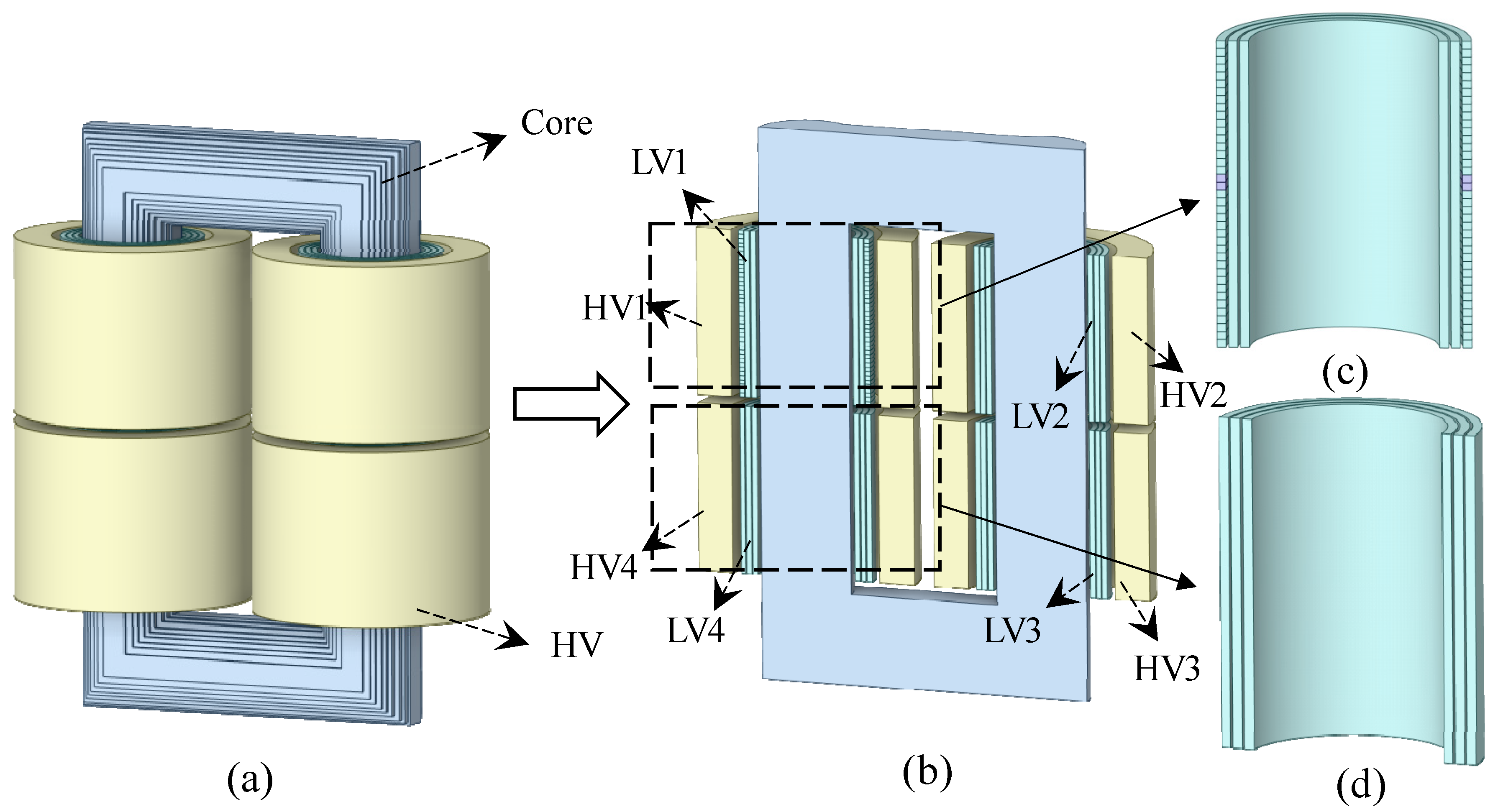
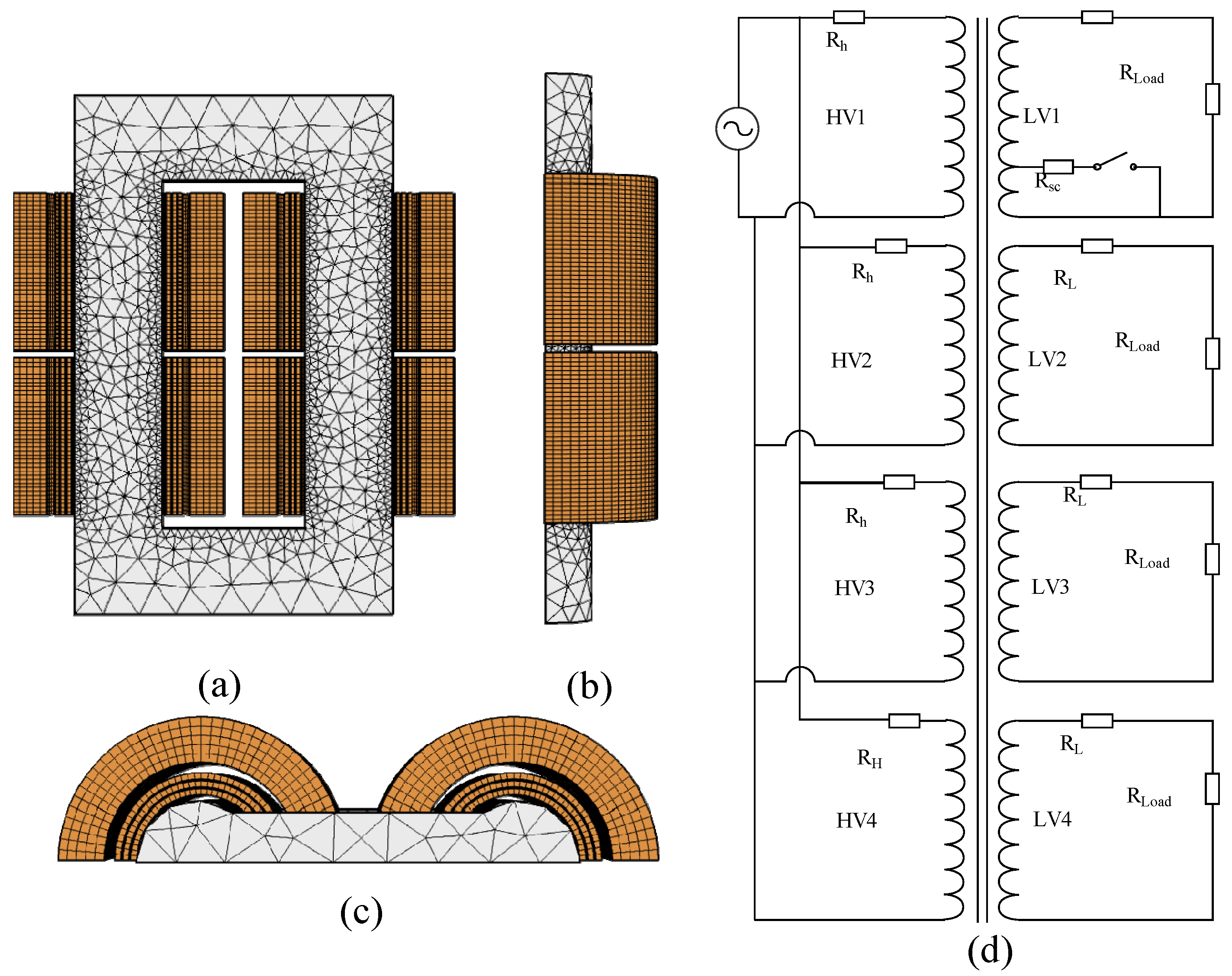
2. Analysis Method and Validation
The three-dimensional finite element method is time-consuming and complex. In order to obtain the results quickly, it is necessary to simplify the original model. Generally, the winding is simplified to a uniform coil and the oil channel is ignored. However, this winding cannot take into account the forces on each turn coil of the winding. On this basis, this paper improves the original model, adopts the 1/2 model, and simplifies the core and high-voltage winding. All coil regions of the layer where the TTF coils are located are established. For the winding without short-circuit, the uniform multi-turn model is used to replace the coil of each layer, and the interlayer flow channel is reserved to meet the geometric similarity of each branch winding. The three-dimensional finite element model of 3600 KVA four split traction transformer is shown in the Figure 1. For the simulation of the model, the following assumptions are made:
Figure 1.
Establishment of simulation model. (a) Original simplification model. (b) Improved simplification model. (c) Simplified form of winding with TTF. (d) Simplified form of winding without TTF.
- The conductivity of the material is constant and the influence of temperature change on the conductivity is ignored.
- The skin effect and proximity effect of windings are neglected.
The split-winding transformer consists of core type core, high voltage winding and low voltage winding. The low voltage winding is divided into four equal capacity parts (LV1, Lv2, LV3, LV4), which can be operated in parallel or independently. The high voltage is divided into four equal capacity branches (LV1, Lv2, LV3, LV4) corresponding to the four low voltage branches one by one, and the four high voltage branches are operated in parallel. The sequence number of each winding is shown in Figure 1b, the parameters of transformer and winding are shown in Table 1. The mesh division of 3D model is shown in Figure 2, with a total of 306,639 units.
Table 1.
Basic parameters of transformer.
Figure 2.
(a) Front view of meshing. (b) Right view of meshing. (c) Top view of meshing. (d) Field circuit coupling circuit.
In the study, the three-dimensional model is solved by field circuit coupling and transient solver in COMSOL, and the time stepping method is backward difference implicit solver. The field circuit coupling circuit solved is shown in Figure 3. is the resistance of high voltage winding, is the resistance of low voltage winding, is the equivalent load resistance (2.5 Ω), is the resistance of short-circuited winding. After the transformer operates for 50 ms, the TTF is realized by switch control.
Figure 3.
The positions of TTFs and the distribution of magnetic flux leakage between HV1 and LV1. (a) Top turn-to-turn fault. (b) Middle turn-to-turn fault. (c) Bottom turn-to-turn fault. (d) The positions of three cases of TTF.
Solution Method
The three-dimensional model is solved by A-V-A method. Based on Maxwell equation and Coulomb gauge, the following governing equations can be obtained:
where, and are the regions with and without eddy current, respectively, is the magnetic vector potential, is the permeability tensor, is the conductivity tensor.
For stranded coil, the skin effect and proximity effect are ignored, and the governing equation of coil domain is rewritten as
where, is the cross-sectional area of a stranded coil, is the number of turns, is the current per turn, and is defined as the coil direction vector, which is the unit vector representing the current direction [11,16].
where
where and are the shape function and volume of the element, respectively. The transformers are usually connected to a voltage source. According to the equivalent circuit model in Figure 4 the matrix form of external circuit equation can be written as
where is the input voltage, and is the leakage inductance and winding resistance, respectively, is the matrix associated with the geometric features of the winding.
Figure 4.
The distribution of radial and axial magnetic flux leakage under the TTFs at 59 ms. (a) Top turn-to-turn fault. (b) Middle turn-to-turn fault. (c) Bottom turn-to-turn fault.
Based on the above formula, the following coupling equation can be obtained
In this system of equations, the unknowns are the nodal values of the vector potential () and the currents () in the external circuits.
The electromagnetic force density is readily available according to Lorentz force law:
The total axial force and radial force on each coil are achieved by calculating the volume fraction of force density.
3. Results and Discussion
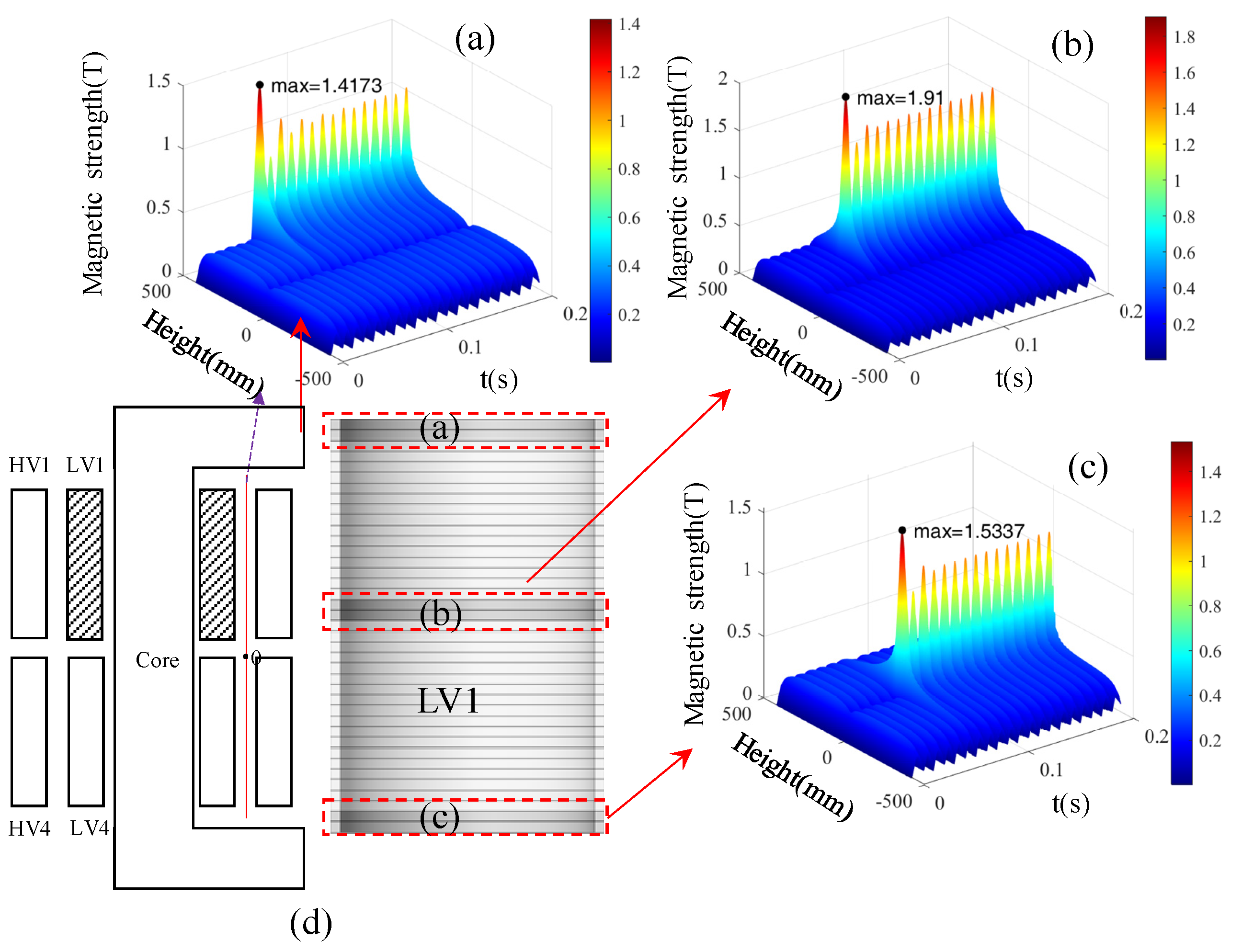
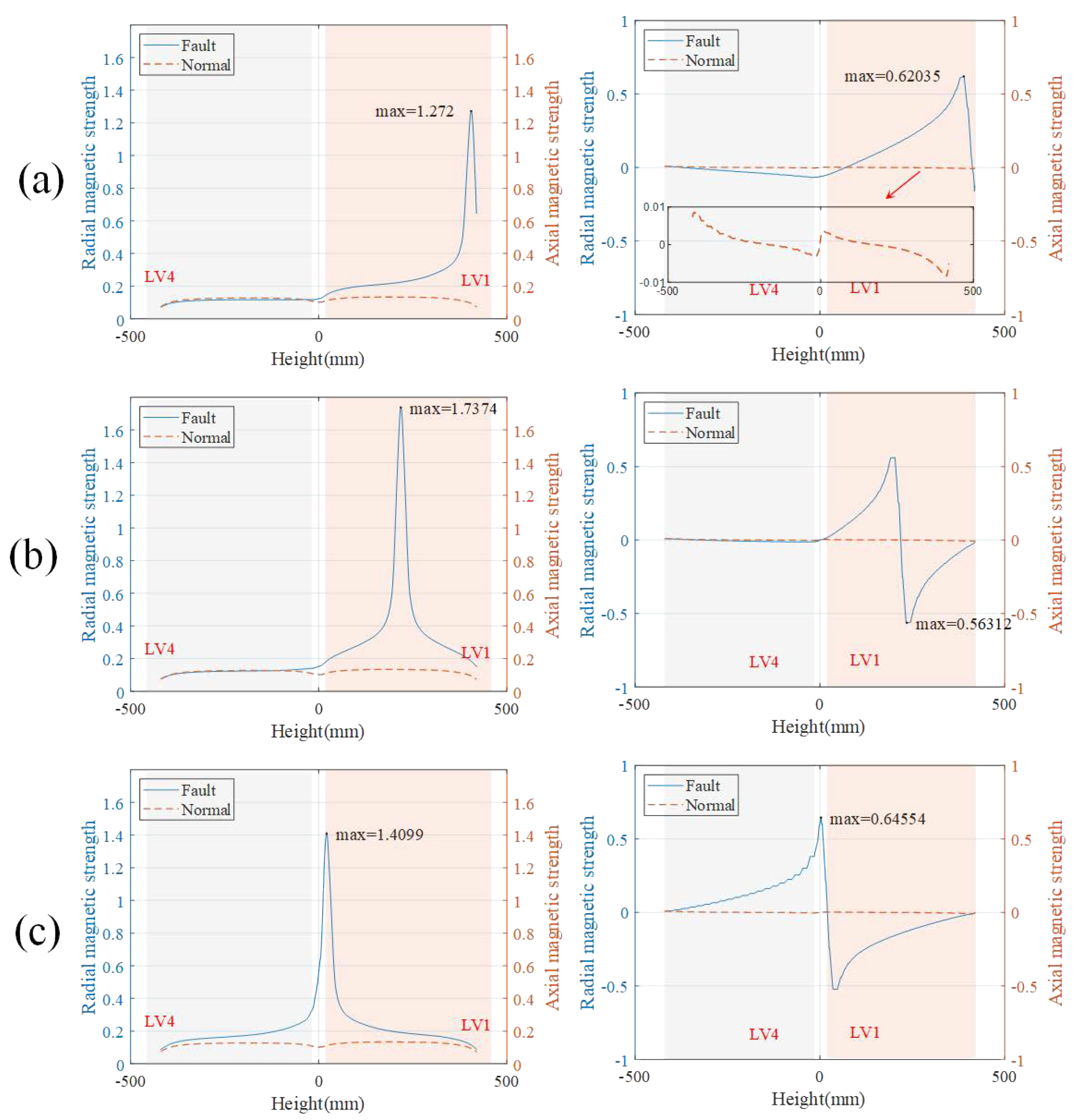
3.1. Magnetic Field Analysis
Nonlinear ferromagnetic materials and branch windings can affect the magnetic field distribution, so the influence of TTFs at different spatial positions is different. In order to comprehensively evaluate the impact of TTFs, the bottom, the middle and the top of two-turns TTF in LV1 low-voltage winding are analyzed. The positions of TTFs and the distribution of magnetic flux leakage between HV1 and LV1 under the TTFs are shown in the Figure 3.
It can be seen from the Figure 3 that the magnetic leakage field at the short-circuit position is distorted, and the distorted magnetic strength results in the increase of the overall magnetic leakage field between the LV1 and HV1. The magnetic strength under the middle TTF is the largest and decreases rapidly along both sides. After the TTF occurs, the leakage magnetic field is maximum at the first peak, which gradually stabilizes with time. The maximum magnetic flux leakage peak is 0.13 T under normal operation. The maximum peak value of top fault is 1.42 T, which is 11 times higher than the normal magnetic strength. The maximum peak value of the middle fault is 1.91 T, which is 14.6 times higher than the normal magnetic strength, and the maximum peak value of the bottom fault is 1.53 T, which is 11.7 times higher than the normal magnetic strength. Then, it can be found that the distortion of leakage magnetic field is the largest under the condition of middle fault, which results in larger radial force of the winding.
The distribution of radial and axial magnetic flux leakage under the TTFs at 59 ms (peak short-circuit current) is shown in Figure 4. Axial magnetic flux leakage accounts for the main part of distorted magnetic flux leakage, so the change trend of axial magnetic density is consistent with that of magnetic density. The axial flux leakage under the middle TTF is the largest and decreases rapidly along both sides. The maximum value of radial flux leakage appears on both sides of the short-circuit positions. The direction of the radial leakage magnetic field on both sides of the short-circuit wire is opposite, and gradually decreases along both sides of the short-circuit position.
Compare the three TTF cases, the peak value of axial magnetic flux leakage is the largest under the middle TTF, the peak value of axial magnetic flux leakage is 1.74 T, and the minimum value of radial magnetic flux leakage is 0.548 T. The axial magnetic flux leakage peak value under the bottom TTF is 1.41 T, and the radial magnetic flux leakage peak value is 0.65 T. When the top TTF occurs, the axial magnetic flux leakage is the smallest, the peak value is 1.18 T, and the radial magnetic flux leakage peak value is 0.62 T.
It can be seen from the axial flux leakage distribution that when the top and middle of LV1 are short-circuited, the axial flux leakage between the channel between the LV1 and the HV1 is affected, while the axial flux leakage does not change significantly in the channel between LV4 and HV4. Under the bottom TTF, the leakage magnetic field between the LV4 and the HV4 is distorted due to the short circuit position adjacent to LV4, and the axial leakage magnetic field between the LV4 and the HV4 is increased. The main reason is that the part of leakage magnetic flux under the bottom TTF generated by the short-circuit current is balanced by the magnetic flux generated by HV4, which increases the HV4 current and results in the increase of the overall magnetic flux leakage in the channel.
In normal operation, the value of radial leakage magnetic field is small, so the radial leakage magnetic field caused by TTF has a greater impact on the original radial leakage magnetic field. Only under the middle TTF, the radial leakage magnetic field is not affected produced by short-circuit current between LV4 and HV4. The radial leakage magnetic field produced by top and bottom TTF current has a great influence on the radial leakage magnetic field between LV4 and HV4. Especially when the bottom TTF occurs, the transverse leakage magnetic field of the channel between LV4 and HV4 is greatly increased, which will lead to a large axial force on the LV4 and HV4 winding.
The magnetic leakage field generated by short-circuit fault makes the core local magnetic saturation, which results in core vibration and local heating. The normal magnetic field and the fault magnetic field of bottom TTF under the maximum of peak short-circuit current are shown in Figure 5.
Figure 5.
The normal magnetic field and the fault magnetic field of bottom TTF under the maximum of peak short-circuit current at 59 ms. (a) Normal magnetic field. (b) Fault magnetic field.
It can be seen from the Figure 5 that the magnetic density of the core at the short-circuit position is locally saturated, and the leakage magnetic field near the short-circuit winding increases correspondingly. The maximum magnetic density of 1.81 t appears near the air region, and the local magnetic saturation appears at the corner of the core on the same side. According to , When the winding is short-circuited, the flux of TTF winding will be offset by the flux of the other windings according to . The local saturation of core flux density is mainly caused by leakage flux produced by short-circuit current.
3.2. Current Analysis
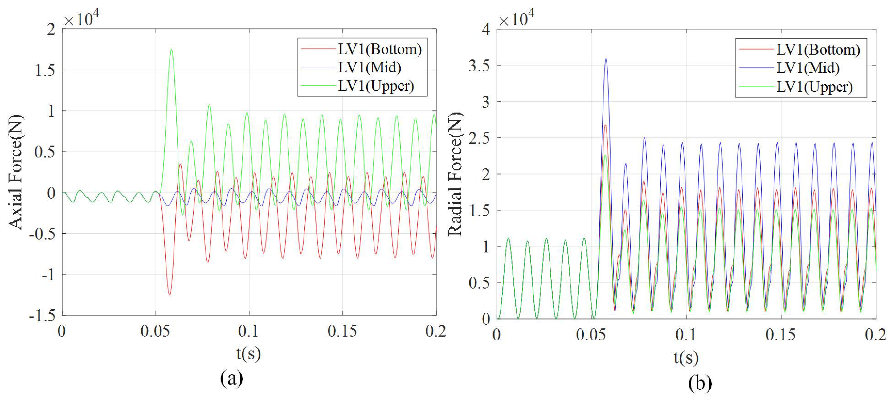
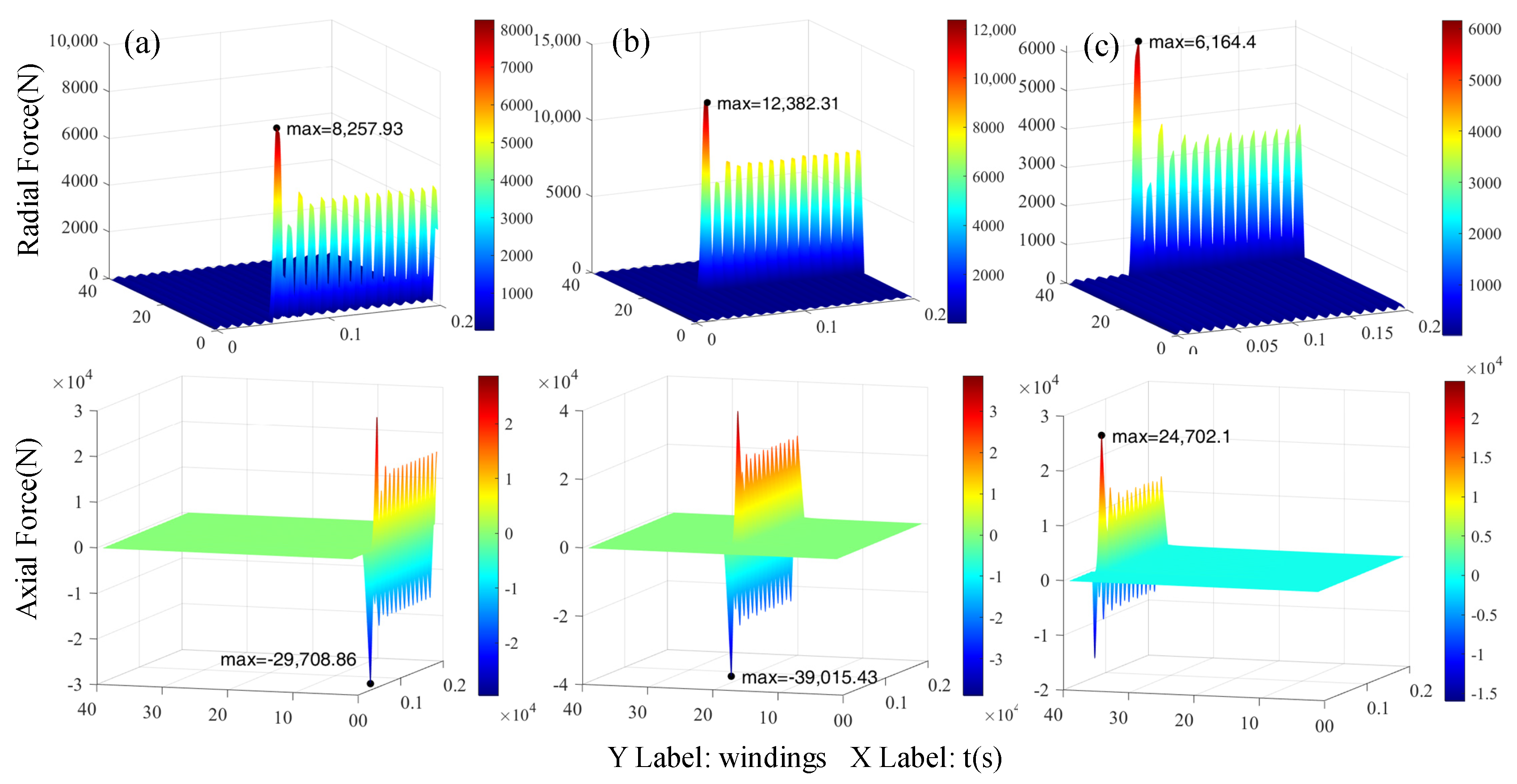
The short-circuit current of the winding is composed of the AC steady-state component of the fundamental frequency and an exponential decay component. The transient time of the short-circuit process is related to the ratio of resistance to reactance of the winding.
where is steady state peak value of short-circuit current, and are winding resistance and leakage reactance of transformer, and are time and angular frequency. Due to the influence of ferromagnetic material and space position, the self-inductance and mutual inductance of TTF winding are different, which leads to different time constant and steady-state current peak value of TTF at different positions.
When TTFs occur in the LV1 winding, a short-circuit loop is formed. The induced voltage of the short-circuit loop acts on the minimum resistance of the winding. Because the winding is similar to an inductive element, the current does not change abruptly, so there is an aperiodic component, which makes the loop current of the short-circuit loop much higher than the rated value.
The current of short-circuit winding and LV1 winding is shown in Figure 6. It can be seen that the peak current of the middle TTF is the largest. The peak value of the middle TTF current is 48 kA, which is 62 times of the normal peak value. The peak current of the bottom TTF is 42 kA, which is 54 times of the normal peak value. The peak current of the top TTF is 35 kA, which is 45 times of the normal peak current.
Figure 6.
The currents of LV1 sort-circuit winding and LV1 winding under three cases of TTFs. (a) The current of LV1 sort-circuit winding (LV1-SC). (b) The current of LV1 winding.
The current of HV1 winding under the TTFs at different positions is shown in Figure 7. When TTFs occur in the LV1, the high-voltage winding needs to balance the magnetic flux produced by short circuit current according to . Therefore, the current of the high-voltage winding increases correspondingly, while the current of the low-voltage winding that is not short-circuited decreases correspondingly due to the decrease of the number of turns. Then, the ampere turn balance is reestablished. Under the middle TTF, the current of HV1 increases and the impedance angle changes obviously. The peak current of HV1 is 1.74 times of the normal value, and the steady-state current of HV1 increases by 45.4%. The steady-state current of HV1 increases by 23% and 11% in the case of top and bottom TTF, respectively. The current of LV1 is reduced correspondingly, and the maximum reduction is 24% in the case of middle TFF, while the steady-state current of LV1 will be reduced by 12% and 11.7% in the case of top and bottom TFF, respectively.
Figure 7.
The current of HV1 winding under the TTFs at different positions.
The peak current multiple and steady-state current multiple of each branch winding under the TTFs at different positions are shown in Table 2 and Table 3, respectively. It can be seen that the current of HV1 is most affected because of the strong magnetic coupling between HV1 and LV1, while the peak current of HV1 is different under different faults. Hv4 and LV4 windings are greatly affected by the bottom short circuit fault. Because the short circuit position is close to HV4 and LV4 windings, the flux linkage generated by LV1 short circuit is offset by the flux linkage generated by HV1 and HV4 windings, which increases the current of HV1 and HV4 windings and decreases the current of LV4 windings.
Table 2.
The peak current multiple of each branch under different short-circuit positions.
Table 3.
The steady-state current multiple of each branch under different short-circuit positions.
It is worth noting that the TTF of LV1 winding has a greater impact on the windings on the same core (HV1, HV4, LV1, LV4), and has a smaller impact on the normal operation of the other core (HV2, HV3, Lv2, LV3).
3.3. Force Analysis
The radial resultant force and axial resultant force of LV1 under the TTFs at different positions are shown in Figure 8. It can be seen from the figure that the axial resultant force of LV1 winding under the top TTF is the largest, with the maximum peak force of 17.5 kN, which is 14.5 times larger than the normal peak force. The axial resultant force of LV1 winding under the middle TTF is the smallest, with the maximum peak force of 1.65 kN, which is 1.3 times larger than the normal peak force. The maximum peak value of axial resultant force caused by the short-circuit at the lower part is 12.5 kN. The peak force is 10.4 times larger than normal.
Figure 8.
The radial resultant force and axial resultant force of LV1 under the TTFs at different positions. (a) The axial resultant force. (b) The radial resultant force.
The low-voltage winding is squeezed inward. It can be seen from the Figure 8 that the radial force of LV1 winding under the middle fault is the largest, and the maximum peak force is 35.9 kN, which is 3.2 times larger than the maximum peak force in normal operation. The radial resultant force of LV1 winding under the top fault is the smallest, and its maximum peak force is 22.6 kN, which is two times larger than the axial resultant force in normal operation. The maximum peak force LV1 winding under the bottom fault is 26.7 kN, which is 2.4 times larger than that in normal operation.
The radial force and axial force of per-turn wire of LV1 outermost winding under three cases of TTFs are shown in Figure 9, with 39 turns of wires in this layer. When the middle part of LV1 is short-circuit, the peak radial force and peak axial force of the short-circuit winding are 12.4 kN and 39 kN, respectively. When the bottom part of LV1 is short-circuit, the peak radial force and axial force of single turn winding are 8.2 kN and 29 kN, respectively. When the top part of LV1 is short-circuit, the peak radial force and axial force of the single turn winding are the smallest, which are 6.2 kN and 24.7 kN, respectively. However, there is a large difference between the reverse force and the forward force in the axial force of the winding, and the difference between the maximum peak force is 4.3 kN.
Figure 9.
The radial force and axial force of per-turn wire of LV1 outermost winding under three cases of TTFs. (a) Top turn-to-turn fault. (b) Middle turn-to-turn fault. (c) Bottom turn-to-turn fault.
The TTF changes the internal magnetic flux leakage and other branch winding currents in the transformer, so the force of other branch windings is also affected. The change multiples of radial and axial peak resultant forces of windings after short circuit are shown in the Table 4 and Table 5, respectively. Compared with the radial force of the winding, the change multiple of the axial force is larger, and more windings are affected. In the three cases of TTFs, the axial force of the top and bottom TTFs changes greatly, while the axial force of the middle TTF changes little.
Table 4.
The change multiples of axial peak resultant forces of windings.
Table 5.
The change multiples of radial peak resultant forces of windings.
The radial magnetic field produced by the short circuit current is opposite on both sides of the short circuit coil, so the force on both sides of the coil is opposite from the center of the short circuit location. The axial resultant force is mainly related to the asymmetry of the magnetic field, while ferromagnetic materials and adjacent windings affect the magnetic field in the transformer, so the top and bottom TTF will have a greater impact on the axial resultant force of the winding.
The radial force fluctuation is small, and the influence on the winding on the other side of the mandrel can be ignored. The influence only exists in the windings of the same core. The damage is the most serious when the middle short-circuit occurs. The radial force of HV1 increases by 3.04 times and that of LV1 increases by 3.22 times.
In summary, it can be concluded that the axially split windings have a high degree of coupling, that is, the axially split windings have weak ability of anti-short circuit. When the split transformer is applied in the field of train transmission, the inter turn short-circuit fault will change the short-circuit impedance at the traction side and the current amplitude of adjacent windings. If the four-quadrant converter adopts the original control strategy, it will cause fundamental circulation and heat the converter, resulting in more serious faults.
4. Conclusions
In this paper, a 3600 kVA four-split winding transformer is taken as an example. This paper presents a simplified three-dimensional model to consider the per-turn coil domain. The model adopts three-dimensional finite element method and field circuit coupling for transient analysis. The magnetic field, force and current of transformer under the TTFs at different positions are analyzed comprehensively. The following conclusions are obtained:
- The results show that the magnetic leakage field is distorted after short circuit, and the magnetic leakage field produced by the TTFs at different positions is different. The maximum axial magnetic flux leakage caused by the middle TTF is 1.74 T, and the maximum radial magnetic flux leakage caused by bottom short circuit is 0.56 T. The distribution of magnetic field in the core is analyzed. When the TTF occurs, the local magnetic saturation of the core is serious, which can result in more severe vibration and noise of the core.
- Based on the analysis of the per-turn force and resultant force of the short-circuit winding, the radial and axial electromagnetic force of the winding under normal operation and TTFs is basically consistent with the distribution law of the axial and radial leakage magnetic field of the winding in the above conclusion. The axial resultant force is increased by 14 times under the top and the bottom TTFs, and the radial resultant force is increased by 3.2 times under the middle TTF. It should be noted that when the middle part of the winding is short circuited, the axial force on both sides of the winding is opposite, resulting in a small axial force of the short-circuit winding, which is only increased by 1.3 times.
- The influence of TTFs at different positions on the current relationship of other windings is studied. The coupling of windings on the same core column is strong, and the coupling between windings on different cores is weak. When the middle TTF occurs, it has the least influence on the current of other windings. In addition, it is worth noting that when the location of TTF is adjacent to the same core winding, the short circuit fault will have a greater impact on current of the adjacent winding. When the bottom is short circuited, the steady-state current of the high-voltage winding axially adjacent to the short-circuit winding increases by 8%, and the steady-state current of the low-voltage winding axially adjacent to the short-circuit winding decreases by 7%, respectively.
- The influence of TTFs at different positions on the force of other windings is studied. The results show that the axial force of the branch winding on the two cores is greatly affected by the TTFs, while the radial force of other windings on the same mandrel has a greater influence, and the change of radial force on the other core column can be ignored.
Author Contributions
Conceptualization, B.X.; methodology, C.Y.; software, Y.D.; validation, C.Y., H.Q. and Y.D.; formal analysis, Y.D.; investigation, Y.D.; resources, C.Y.; writing—original draft preparation, Y.D.; writing—review and editing, C.Y.; visualization, Y.D.; supervision, C.Y.; project administration, C.Y.; funding acquisition, C.Y. All authors have read and agreed to the published version of the manuscript.
Funding
This work was supported in part by the National Natural Science Foundation of China under Grant U2004183, 51507156. And in part by the Science and Technology Research Project of Science and Technology Department of Henan Province under Grant 202102210100 and 202102210104, and in part by the Foundation for Key Teacher of Henan Province 2018GGJS087.
Data Availability Statement
The data presented in this study are available on request from the corresponding author.
Acknowledgments
I would like to acknowledge Cunxiang Yang, Hongbo Qiu, for their guidance during this research. Thanks to Bin Xiong for his guidance on topic selection.
Conflicts of Interest
The authors declare no conflict of interest.
References
- Amoiralis, E.I.; Tsili, M.A.; Kladas, A.G. Transformer Design and Optimization: A Literature Survey. IEEE Trans. Power Deliv. 2009, 24, 1999–2024. [Google Scholar] [CrossRef]
- Chase, D.D.; Garin, A.N. Split Winding Transformers. Trans. Am. Inst. Electr. Eng. 1934, 53, 914–922. [Google Scholar] [CrossRef]
- Kladas, A.G.; Papadopoulos, M.P.; Tegopoulos, J.A. Leakage Flux and Force Calculation on Power Transformer Windings under Short-Circuit: 2D and 3D Models Based on the Theory of Images and the Finite Element Method Compared to Measurements. IEEE Trans. Magn. 1994, 30, 3487–3490. [Google Scholar] [CrossRef]
- Gholami, M.; Hajipour, E.; Vakilian, M. A Single Phase Transformer Equivalent Circuit for Accurate Turn to Turn Fault Modeling. In Proceedings of the 2016 24th Iranian Conference on Electrical Engineering (ICEE), Shiraz, Iran, 10–12 May 2016; pp. 592–597. [Google Scholar] [CrossRef]
- Zhang, H.; Yang, B.; Xu, W.; Wang, S.; Wang, G.; Huangfu, Y.; Zhang, J. Dynamic Deformation Analysis of Power Transformer Windings in Short-Circuit Fault by FEM. IEEE Trans. Appl. Supercond. 2014, 24, 1–4. [Google Scholar] [CrossRef]
- Salon, S.; LaMattina, B.; Sivasubramaniam, K. Comparison of Assumptions in Computation of Short Circuit Forces in Transformers. IEEE Trans. Magn. 2000, 36, 3521–3523. [Google Scholar] [CrossRef]
- Arturi, C.M. Electromagnetic Force Calculations on a 3-Phase Autotransformer under Time-Varying Fault by a 3D Non-Linear Finite Element Code. IEEE Trans. Magn. 1993, 29, 2010–2013. [Google Scholar] [CrossRef]
- Azizian, D.; Vakilian, M.; Faiz, J. A New Multi-Winding Traction Transformer Equivalent Circuit for Short-Circuit Performance Analysis. Eur. Trans. Electr. Power 2014, 24, 186–202. [Google Scholar] [CrossRef]
- Sobouti, M.A.; Azizian, D.; Bigdeli, M.; Gharehpetian, G.B. Multi-Conductor Transmission Line Model of Split-Winding Transformer for Frequency Response and Disk-to-Disk Fault Analysis. Ijars Int. J. Eng. 2021. [Google Scholar] [CrossRef]
- Renyuan, T.; Shenghui, W.; Yan, L.; Xiulian, W.; Xiang, C. Transient Simulation of Power Transformers Using 3D Finite Element Model Coupled to Electric Circuit Equations. IEEE Trans. Magn. 2000, 36, 1417–1420. [Google Scholar] [CrossRef]
- Leonard, P.J.; Rodger, D. Voltage Forced Coils for 3D Finite-Element Electromagnetic Models. IEEE Trans. Magn. 1988, 24, 2579–2581. [Google Scholar] [CrossRef]
- Nakata, T.; Takahashi, N. 3-D Finite Element Method for Analyzing Magnetic Fields in Electrical Machines Excited from Voltage Sources. IEEE Trans. Magn. 1988, 24, 2582–2584. [Google Scholar] [CrossRef] [Green Version]
- Kumbhar, G.B.; Kulkarni, S.V. Analysis of Short-Circuit Performance of Split-Winding Transformer Using Coupled Field-Circuit Approach. IEEE Trans. Power Deliv. 2007, 22, 936–943. [Google Scholar] [CrossRef] [Green Version]
- Li, L.; Liu, X.; Zhu, G.; Chen, H.; Gao, S. Research of Short-Circuit Performance of a Split-Winding Transformer With Stabilizing Windings. IEEE Trans. Appl. Supercond. 2019, 29, 1–6. [Google Scholar] [CrossRef]
- Azizian, D. Nonlinear Behavior Analysis of Split-Winding Dry-Type Transformer Using a New Star Model and a Coupled Field-Circuit Approach. Arch. Electr. Eng. 2016, 65, 773. [Google Scholar] [CrossRef] [Green Version]
- Wang, J.-S. A Nodal Analysis Approach for 2D and 3D Magnetic-Circuit Coupled Problems. IEEE Trans. Magn. 1996, 32, 1074–1077. [Google Scholar] [CrossRef]
Publisher’s Note: MDPI stays neutral with regard to jurisdictional claims in published maps and institutional affiliations. |
© 2021 by the authors. Licensee MDPI, Basel, Switzerland. This article is an open access article distributed under the terms and conditions of the Creative Commons Attribution (CC BY) license (https://creativecommons.org/licenses/by/4.0/).


