Article

Optimal Quick-Response Variable Structure Control for Highly Efficient Single-Phase Sine-Wave Inverters

Department of Electrical Engineering, I-Shou University, No. 1, Sec. 1, Syuecheng Rd., Dashu District, Kaohsiung City 84001, Taiwan
*
Author to whom correspondence should be addressed.
Processes 2021, 9(12), 2132; https://doi.org/10.3390/pr9122132
Submission received: 21 September 2021 / Revised: 18 November 2021 / Accepted: 22 November 2021 / Published: 25 November 2021
(This article belongs to the Special Issue Application of Power Electronics Technologies in Power System)

Abstract

:
This paper puts forward an optimal quick-response variable structure control with a single-phase sine-wave inverter application, which keeps harmonic distortion as low as possible under various conditions of loading. Our proposed solution gives an improvement in architecture in which a quick-response variable structure control (QRVSC) is combined with a brain storm optimization (BSO) algorithm. Notwithstanding the intrinsic resilience of a typical VSC with respect to changes in plant parameters and loading disruptions, the system state convergence towards zero normally proceeds at an infinitely long-time asymptotically, and chattering behavior frequently takes place. The QRVSC for ensuring speedy limited-time convergence with the system state to the balancing point is devised, whilst the BSO will be employed to appropriately regulate the parametric gains in the QRVSC for the elimination of chattering phenomena. From the mix of both a QRVSC together with a BSO, a low total harmonic distortion (THD) as well as a high dynamic response across different types of loading is generated by a closed-loop inverter. The proposed solution is implemented on a practicable single-phase sine-wave inverter under the control of a TI DSP (Texas Instruments Digital Signal Processor). It has experimentally shown the simulation findings as well as the mathematical theoretical analysis, displaying that both quick transient reaction as well as stable performance could be obtained. The proposed solution successfully inhibits voltage harmonics in compliance with IEEE 519-2014’s stringent standard of limiting THD values to less than 5%.

1. Introduction

Sine-wave inverters with the rising number of concerns have found widespread applications in emergency backup power or renewable energy conversion systems, such as uninterruptible power supplies, solar power generation systems, and wind power generation systems [1,2]. It is imperative that the sine-wave inverters deliver a superior level of quality alternating current (AC) output-voltage through the use of feedback controllers offering reduced total harmonic distortion (THD) as well as quick dynamical responsiveness [3,4,5]. More specifically, there are some inverter-based applications such as computers, programmable controllers, and variable frequency drives that often need AC power. They must properly handle the harmonics caused by nonlinear loads, which need to be limited to less than 5% of the voltage THD in accordance with IEEE (Institute of Electrical and Electronics Engineers) standard 519-2014 [6] and below 8% of the voltage THD according to European standard EN (European Norm) 50160:2010 [7]. A top performance single-phase sine-wave inverter would be expected to furnish a low distortion output voltage, quick dynamics in response, as well as having virtually null steady-state errors. There are many ways in which proportional-integral (PI) controllers may be used for meeting such expectations for the improvement of single-phase sine-wave inverter behavior; they are nonetheless susceptible to undetermined interferences [8,9,10,11]. Consideration has been made in the literature regarding a couple of available controlling methods, such as deadbeat control, the H-infinity scheme as well as repetitive control [12,13,14,15,16,17]. It is feasible to derive high-grade voltage outputs through the use of deadbeat control. That being said, it is greatly determined by the complexity of the measurement parameters [12,13]. In spite of the fact that there is some uncertainty in the system that is resolved by the H-infinity and repetitive control methods, the sophistication of their control involves additional computations [14,15,16,17].
Variable structure control (VSC) with the sliding mode principle has been characterized as impervious to the changing parameters of the plant as well as interference from external loads [18,19,20]. These VSC systems adopting the switching method of control enforce attainment and preservation of a predefined sliding surface for the system state. It is during the course of the VSC process that its system state is actuated to the sliding surface, as well as sliding towards the origination point following the surface after it has arrived at the surface [21,22]. It is quite fashionable for controllers of sine-wave inverters which are conceived via VSC. One unidirectional sliding of functions has been exploited to carry out for the full range of control purposes. When the steady-state performance is admissible, there is worse transient activity [23]. There are a number of ways in which the use of uniform sliding functions may be amended by multiple loop control, but steady-state inaccuracies are encountered. Additionally, chattering continues to remain, despite the fact that it affords rapid transients [24,25]. With a corrective approach which is built on the idea of discrete-time VSC, a modification methodology was prepared. The chatter gets mitigated, while the steady state properties do not prove desirable [26]. A conjunction of both optimum design principles as well as feed-forward options has been consolidated into the discrete VSC, resulting in exceptionally efficient follow-up. It is not always feasible for a system path which completely matches the sliding surface, creating appreciable levels of distortion in response to irregular fluctuations [27]. Upgraded VSC with the presence of chattering surrounding the sliding surface could be acquired by additive integral correction [28,29]. It is suggested that a structurally simplistic as well as easily calculable VSC allows a sound response in transients, while the steady state characteristics tend to be disappointing [30]. There is a constant switching frequency incorporated in the VSC. This approach involves a convoluted physical configuration, while the operational response seems to be promising [31]. All these sliding surfaces referred to in the foregoing behave linearly as well as have limitless time for convergence of the system states.
Aiming at realizing a high degree of control accuracy, one type of presented QRVSC pertaining to a non-linear sliding surface has been advanced [32,33], which is equipped with a system state capable of narrowing down to the original point during a limited time [34,35,36,37]. However, as long as a fitting QRVSC parametric design is absent, a high level of harmonic distortion would arise from the sine-wave inverter output, which worsens both the availability and flexibility. Instead of the usual evolution algorithms, brain storm optimization (BSO) algorithm originated from bionomics; its conceptual as well as philosophical background comes from simulating human creative problem solving by group behavioral intelligence (i.e., the emulation of brainstorming in the course of human conferencing) [38,39]. This algorithm seeks the optimum resolution in terms of aggregation, renewal as well as variability, which has been used with great success in many sequential and discrete optimum projects [40,41,42]. As such, it is straightforward that measurement of the control gain on the QRVSC could be optimally ascertained from the BSO, permitting achievement of the low level of distortion inverter output voltage. Together with QRVSC and BSO, it is shown that the proposed system delivers an improvement in the steady-state and transient responsiveness of the sine-wave inverter which is sufficient to afford a qualitative level of AC output. Both numerical simulations and experimental results finalize the practicability as well as the strengths of the proposed controlling solution. In the final summary, we know that once the inverter is subjected to a nonlinear load, its output voltage is severely distorted and the system’s steady-state response exhibits inaccurate tracking behavior. The main contribution of this paper is to establish a good transient and steady-state response by using the fast convergence QRVSC with cleverly introducing integral action in the control law. Then, the BSO can be used to adjust the QRVSC parameters to eliminate the chattering, obtaining a global optimum and building a high-performance inverter. The paper has been organized into the following sections. Section 2 depicts the single-phase sine-wave inverter architecture and dynamic model. Section 3 elaborates the incorporation of the quick-response variable structure control (QRVSC) together with the brain storm optimization (BSO), covering the choice of the sliding function, the designing of the proportional-integral power reaching law, as well as the optimum of the QRVSC parameters. In the part of Section 4, it shows the outcome of the simulations and prototype experiments applying the proposed solution to the converter, where a discussion and comparison with previous literature works are presented. Conclusions are drawn in Section 5.

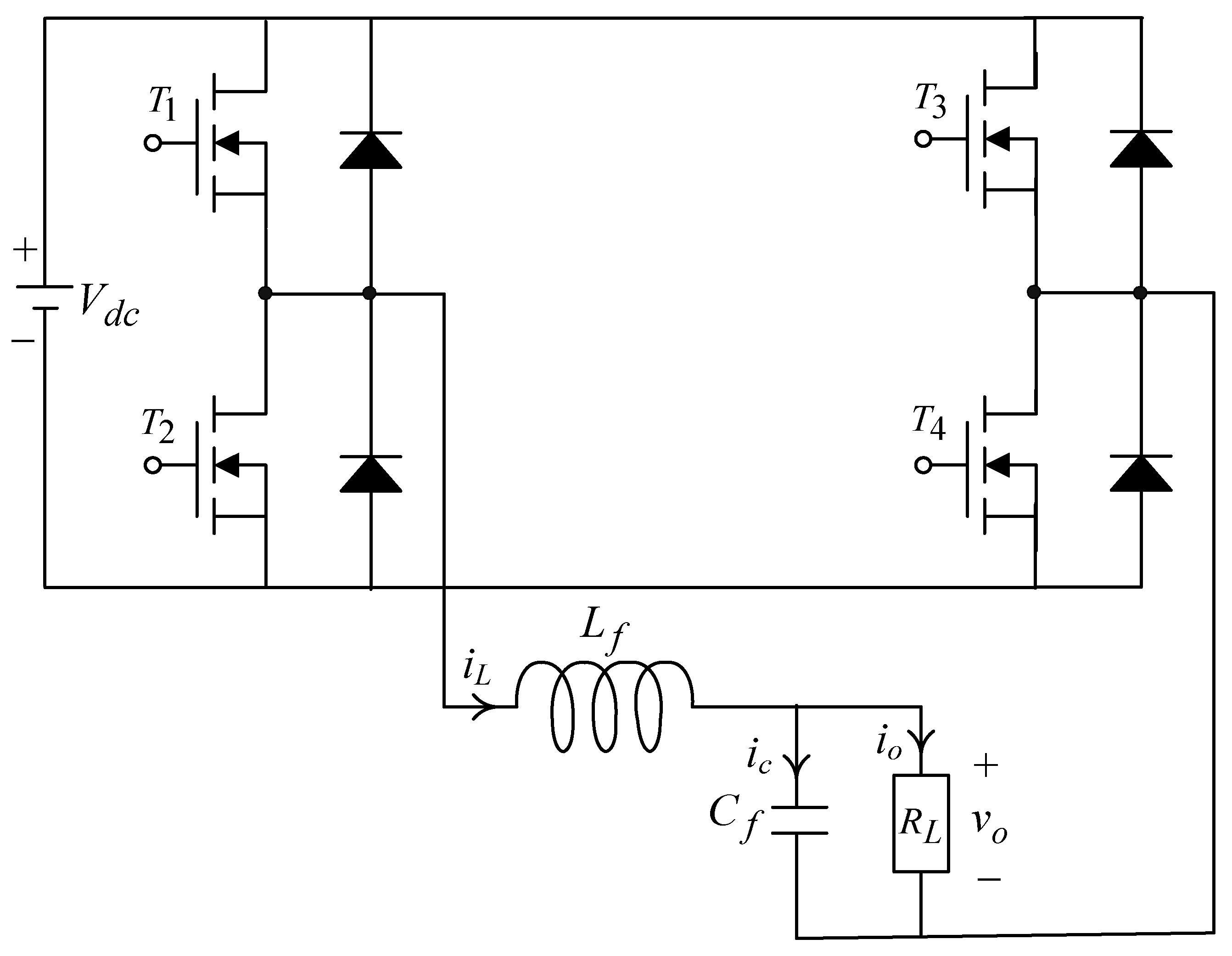
2. Description of the Dynamic Model with a Single-Phase Sine-Wave Inverter

An illustration of a frame diagram relating to a single-phase sine-wave inverter appears in Figure 1. It is possible to visualize both the inductor-capacitor filter and the applied load, which is to be operated as a plant in a closed-loop dynamic response system. The load is either a resistance type loading or a TRIAC series coupled to a resistance loading, and/or a fully waved diode rectifier loading.
For a single-phase sine-wave inverter with an inductor-capacitor filter, the dynamical action may be characterized by the state equations defining x 1 = v o and x 2 = v ˙ o below.
[ d x 1 d t d x 2 d t ] = [ 0 1 a 1 a 2 ] [ x 1 x 2 ] + [ 0 b ] u c
where a 1 = 1 / L f C f , a 2 = 1 / R L C f , b = K i n v / L f C f , and u c stands for control signal. An assumption is made that the switching frequency is sufficiently high to disregard the dynamics of the inverter, i.e., it is permissible to model the inverter as a constant gain K i n v equivalent to V d c / V ¯ t r i , in this case V ¯ t r i means the magnitude of the triangle wave from the sine pulse width modulation. The derivative equations of error depicting the system, taken from Figure 1, give the following:
[ d e ˜ 1 d t d e ˜ 2 d t ] = [ 0 1 1 L f C f 1 R L C f ] [ e ˜ 1 e ˜ 2 ] + [ 0 K i n v / L f C f ] u c [ 0 v r e f L f C f + 1 R L C f d v r e f d t + d 2 v r e f d t 2 ]
where e ˜ 1 = v o v r e f , e ˜ 2 = e ˜ ˙ 1 , v r e f is the voltage of the sine reference voltage. The parameter e ˜ 1 acts as a measurement of change from v r e f to v o . Considering that there is a fully customized signal for the control, it will be sufficient for the overall system (2) to remain in a stable state as well as converging towards zero. This is why the output of the inverter continues to be identical to expectations. Both the explanation and further deduction for the control design are presented hereafter.

3. Control Design and Parameter Optimization

As a matter of conciseness of analysis, the (2) leads to a redefinition of the following second-order non-linear formulation:
e ˜ ˙ 2 = A + B u c + δ v ¨ r e f
where A = 1 L f C f e ˜ 1 1 R L C f e ˜ 2 , B = K i n v L f C f , and δ = 1 L f C f v r e f 1 R L C f v ˙ r e f signifies inner parametric variability of the plant, as well as outside loading interferences, which is restricted to δ κ , here κ is a positive number.
The sliding surface in response to the error state Equation (3) to secure convergence quickly with no singularity occurring for a limited-time could be devised as:
s = e ˜ 1 + 1 Γ e ˜ 2 l / m
where Γ > 0 , l as well as m have positive odd numbers with 0.5 < l / 2 m < 1 . Then, with a view to accessing the sliding surface speedily, it is necessary to recreate a QRVSC on the basis of a proportional-integral power reaching law in the following way:
s ˙ = K p ( s + sgn ( s ) K p ) sgn ( s ) K i 0 t | s | q d t
where K i > 0 , K p > 0 , q > 1 , and A continuous function s c = s c / | s c | + ε carrying a proper positive number ε is selected instead of the sgn function to impair the chattering.
Following the procedure in (4) and (5), a QRVSC control law u c becomes
u c = B 1 [ δ + ( e ˜ 1 + Γ m l e ˜ 2 2 l / m ) + K p ( s + sgn ( s ) K p ) + sgn ( s ) K i 0 t | s | q d t + v ¨ r e f ]
Proof: It is hypothesized that the candidates for the Lyapunov’s function are listed here:
V = 1 2 s 2
It is straightforward to deduce a time derivative from V following the trajectory action (3) together with the control law (6):
V ˙ = s s ˙ = s ( e ˜ 1 + 1 Γ e ˜ 2 l / m 1 e ˜ ˙ 2 ) s [ K p ( s + sgn ( s ) K p ) + sgn ( s ) K i 0 t | s | q d t ) ]
The fact that it becomes clear from (8) for s , as well as e ˜ 2 not being identical to zero, makes V ˙ smaller than zero. The case as such corresponds to the stability theorem of Lyapunov, where a potently unsusceptible QRVSC closed-loop system is expected to merge into an area of equilibrium with a quick limited period of time. One of the most important issues facing the sine-wave inverter is that there may be a substantial amount of loading interference, which contributes to a less acceptable follow-up capability with respect to the system (3). Then, it happens that the output voltage coming from the sine-wave inverter does not match well to the requisite sine wave. The search for the optimum values ascribed to the QRVSC parameters in (5) for retaining the single-phase sine-wave inverter’s satisfied operation would be a requirement. For this reason, optimum values of QRVSC parameters can be attained globally through the brain storm optimization (BSO) algorithm, which removes the chattering and also obviates burdensome, as well as time-consuming, trying error considerations. The BSO algorithm is analogous to the collective brainstorming behavior of a population in solving a problem, i.e., each individual in the BSO algorithm represents a potential solution to the problem, and the best solution to the problem is found through the evolution and fusion of individuals in a process of individual renewal. First, a population of r individuals, each a vector in the h -dimensional space, is randomly generated in the domain defined by the optimization problem. The j th individual is denoted as
ψ j = ( ϕ j 1 , ϕ j 2 , , ϕ j h ) ,   j = 1 ,   2 , , r
After the initialization of the individuals, the following (1) to (5) steps are followed by an overlapping process in which a r new individual is generated in each round:
(1)
Population clustering: The individuals of the population are clustered into υ subgroups using k-means, and then the individuals are ranked according to the fitness function, with the best fitness value in each subgroup being defined as the central individual and the rest as general individuals.
(2)
Individual variation: A random number w 11 between 0 to 1 is randomly generated and if it is greater than a pre-defined probability parameter w 1 , the central individual of a subgroup is randomly selected and replaced with a new randomly generated individual.
(3)
Generation of new individuals: a random number w 2 j between 0 to 1 with a pre-determined probability parameter w 2 is generated at random and compared with w 2 . The latter is generated in the following two ways:
a.
If w 2 j w 2 , a subgroup is randomly selected and either the central individual of the subgroup is chosen or a general individual is randomly selected as the candidate ψ y h .
b.
If w 2 j < w 2 , then two subgroups are randomly selected and either two subgroup centroids are selected or a general individual is randomly selected in each subgroup as ψ y h 1 and ψ y h 2 respectively, which are then combined according to Equation (10) to give the candidate ψ y h .
ψ y h = μ ψ y h 1 + ( 1 μ ) ψ y h 2
where 0 < μ < 1 .
The candidate individual ψ y h plus the difference variation ψ r h generates a new individual, as in Equation (11).
ψ r h = { R A N D O M ( E h , F h ) , R A N D O M ( ) < Y α ψ y h + R A N D O M ( ) × ( ϕ 1 ϕ 2 ) ,   otherwise
where ψ y h is the hth dimension of the selected individual, ψ r h is the hth dimension of the generated individual, E h and F h are the upper and lower bounds of the dth dimension, ϕ 1 and ϕ 2 are two different individuals selected in the full domain, and Y α is the openness probability, typically set between 0.001 to 0.01.
(4)
Individual selection: The adaptation function value of the new individual ψ r h is compared with the adaptation function value of the candidate individual ψ y h , and the individual with a good adaptation degree enters the next generation; the operation of generating a new individual is repeated, and when an r new individual is generated, it enters the next overlapping procedure.
(5)
If an individual meets the optimal solution conditions or the pre-defined number of overlapping generations, the algorithm ends; otherwise, the procedure is repeated to start a new overlapping procedure.
Since the size of the k-means clusters is constant, and needs to be set a priori, a large number of clusters leads to a speedy convergence of the algorithm. A large number of clusters causes the algorithm to converge faster and makes it harder to converge. Smaller clusters produce multiple clusters that merge into a single cluster, increasing the difficulty of optimizing the search. In addition, the initial clustering centers are not easy to choose, and if they are not chosen properly, good clustering results will not be obtained. Therefore, to improve the global search capability of the algorithm, we use the individual selection method of the (12) and (13):
( ϕ n ) = j = 1 F h | g ( ϕ n ) g ( ϕ j ) |
and
w j = j = 1 F h | g ( ϕ n ) g ( ϕ j ) | n = 1 F h j = 1 F h | g ( ϕ n ) g ( ϕ j ) |
where ϕ n and g ( ϕ n ) denote the nth individual and the adaptation value for that individual, respectively. It can be seen from Equation (11) that, compared to the traditional Gaussian variation, the difference variation with only a mixture of random functions and arithmetic operations is significantly less computationally intensive and faster, and the variation is generated based on other individuals in the contemporary population, which can be adapted to the dispersion of the individuals in the population. In addition, Equation (13) shows that as ϕ n moves farther away from the cluster center, the value of ( ϕ n ) increases, and w j increases as well, thereby raising the probability that ϕ n will be selected. This reduces the probability of selection of individuals near the cluster center and increases the probability of selection of outlying individuals, allowing individuals with greater differences from the cluster center to be selected, thus expanding the diversity of the population and jumping out of the zone extremes. Therefore, by improving (11)–(13), the algorithm can compensate for the shortcomings of the traditional brainstorming optimization algorithm, which tends to fall into the regional optimum during the search process, thus effectively improving the clustering accuracy and performance of the algorithm.

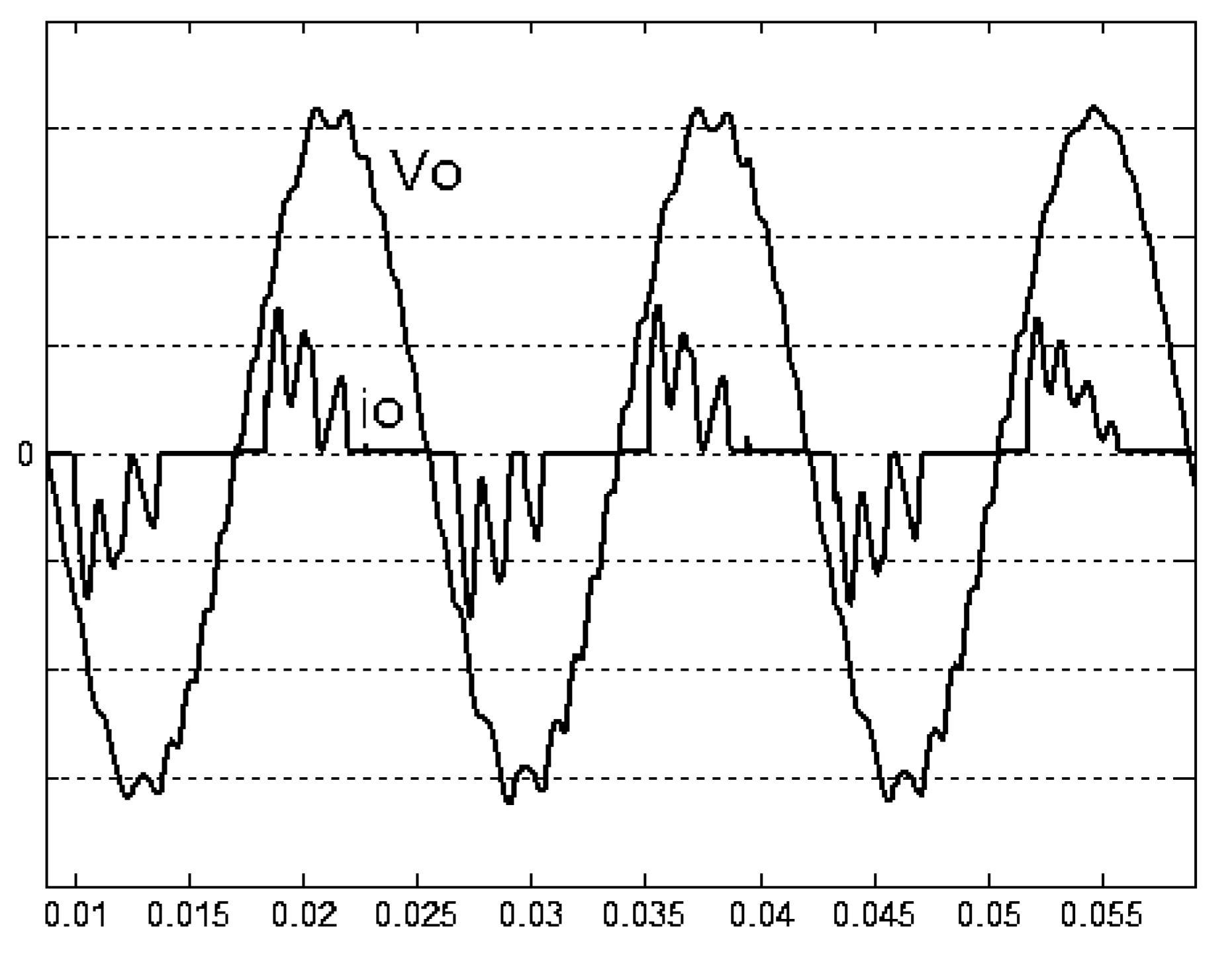
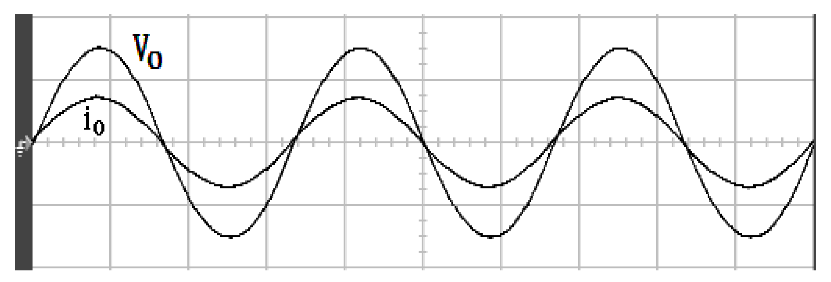
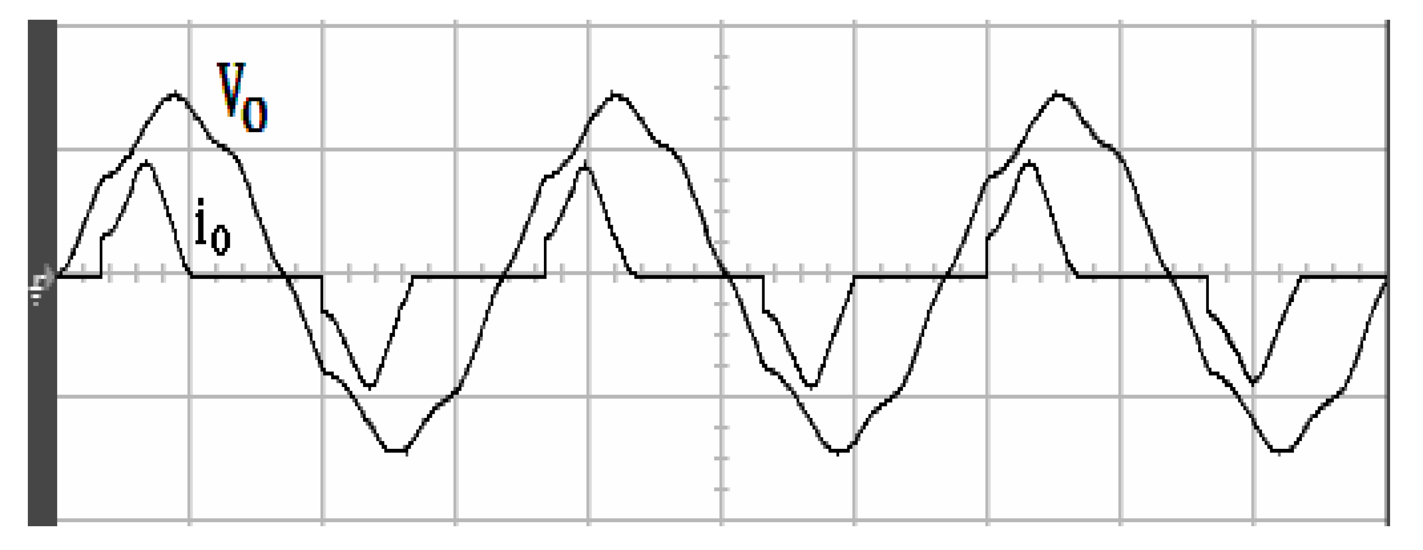
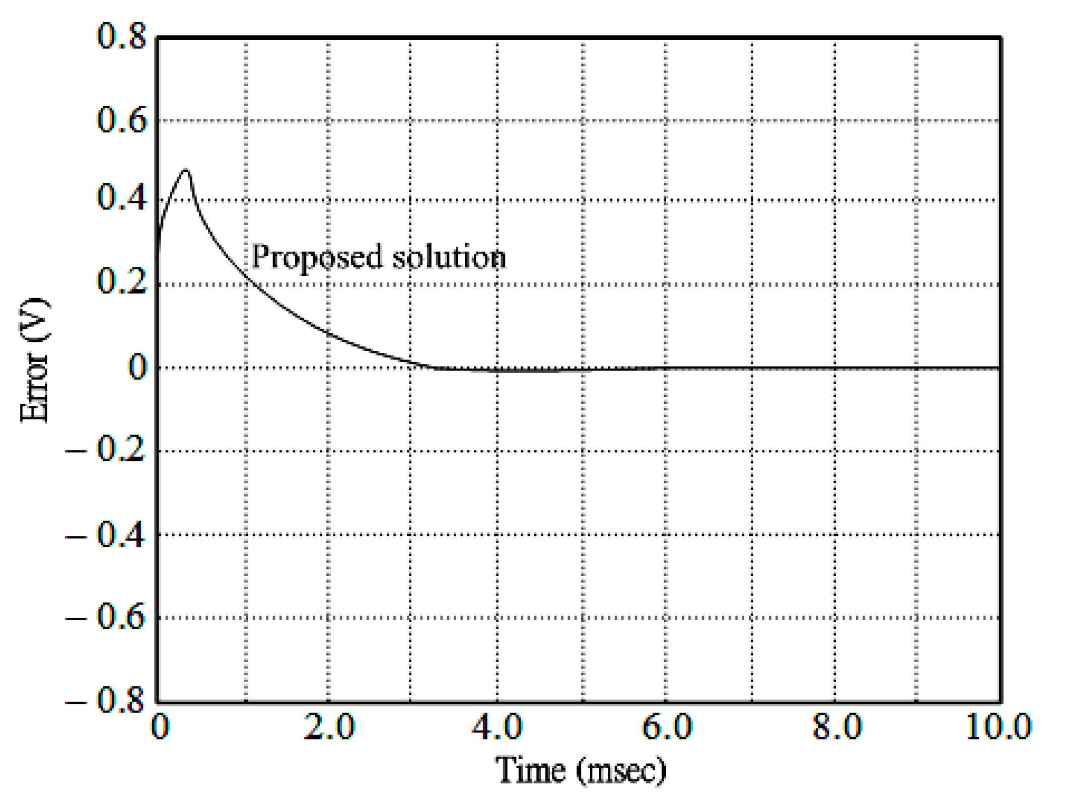
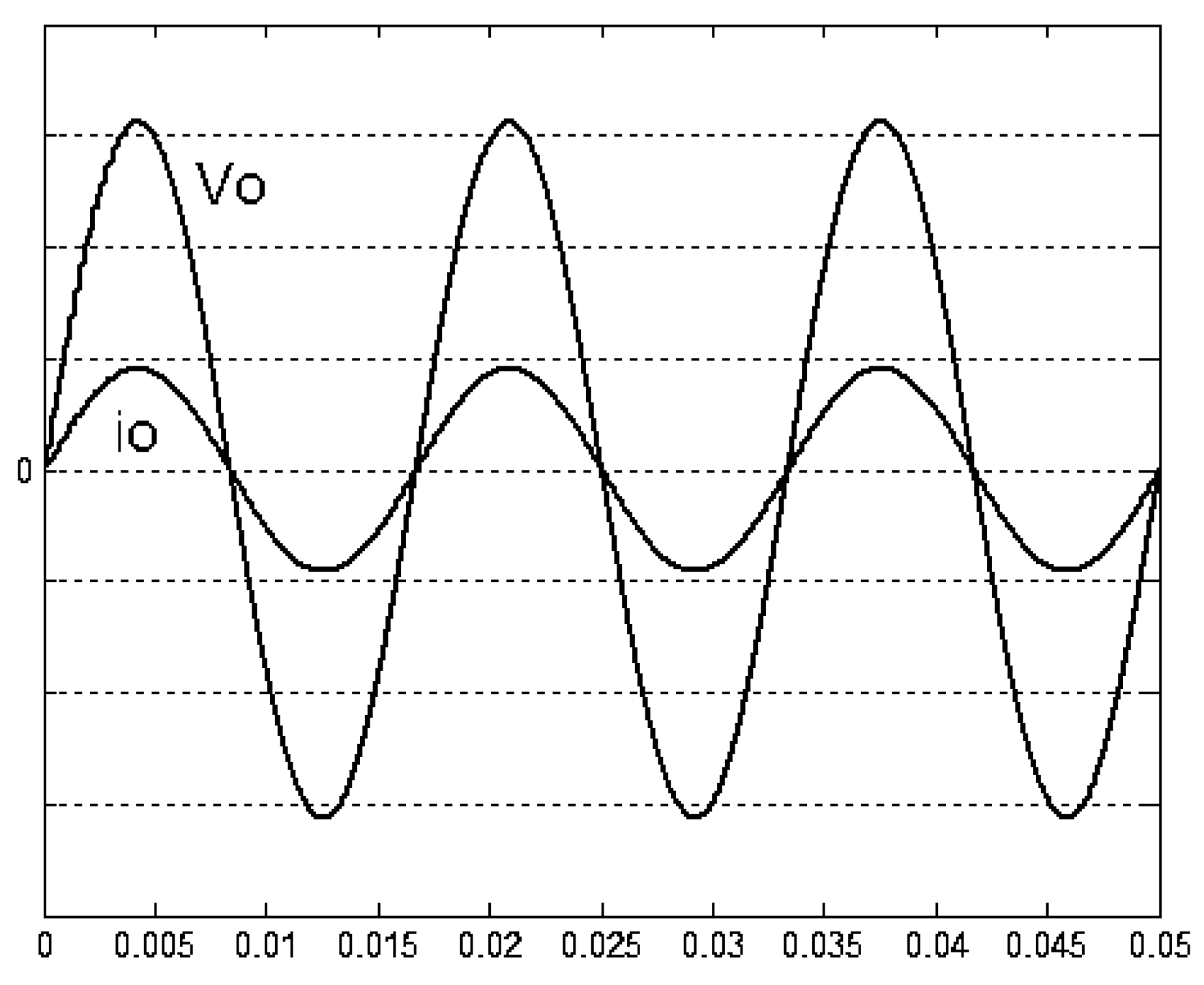
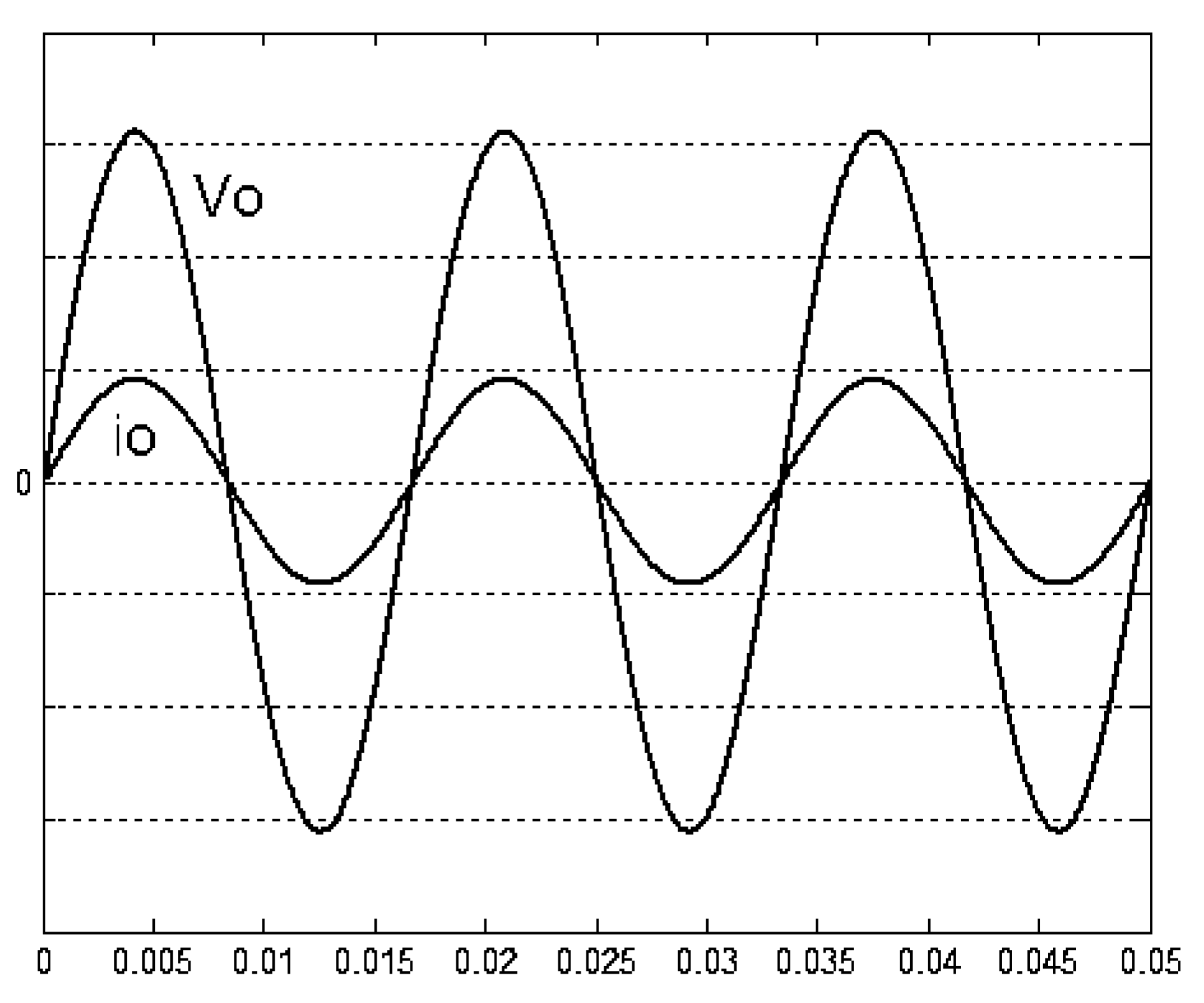
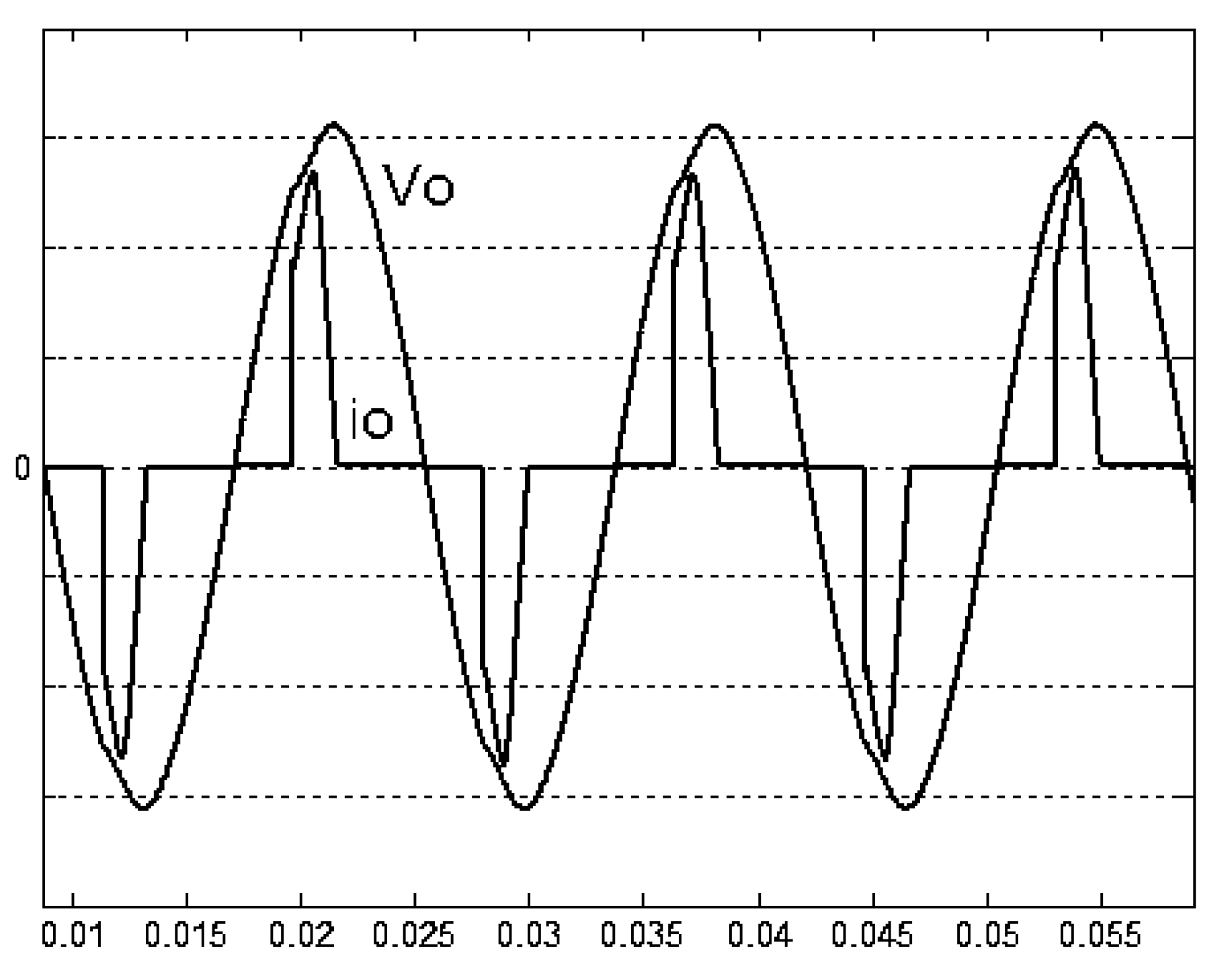
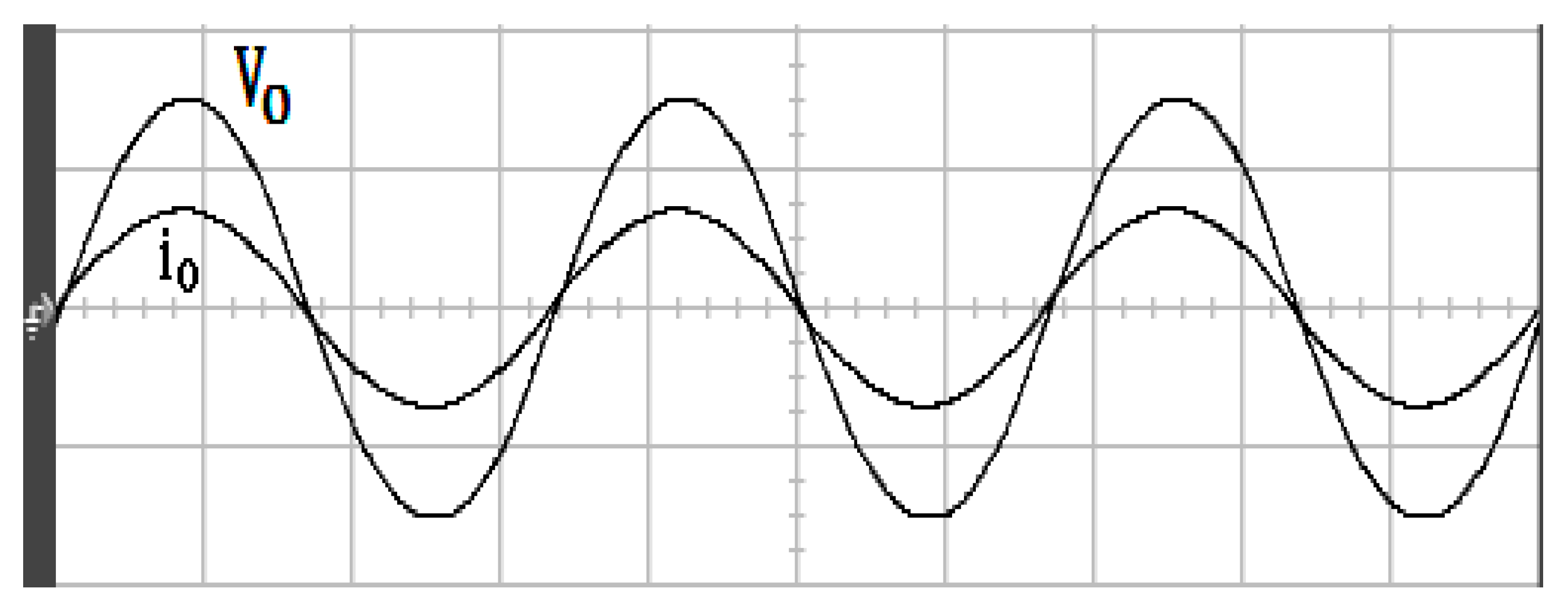
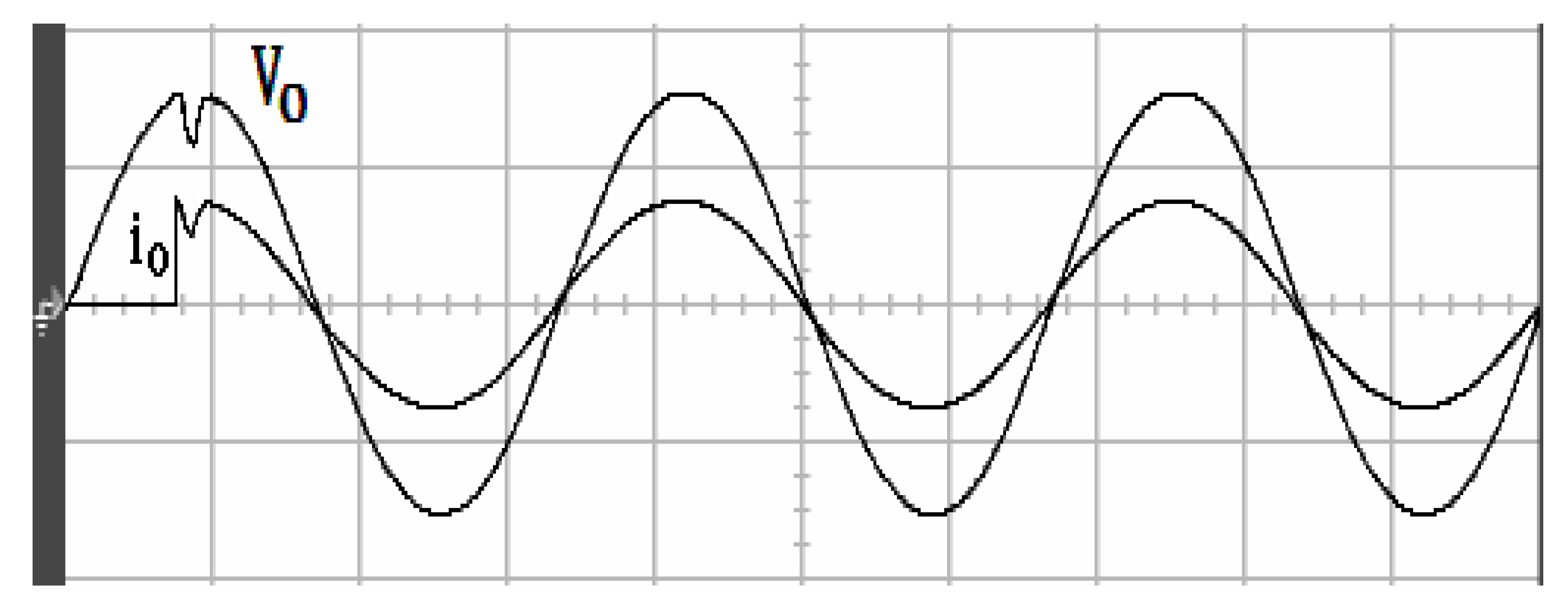
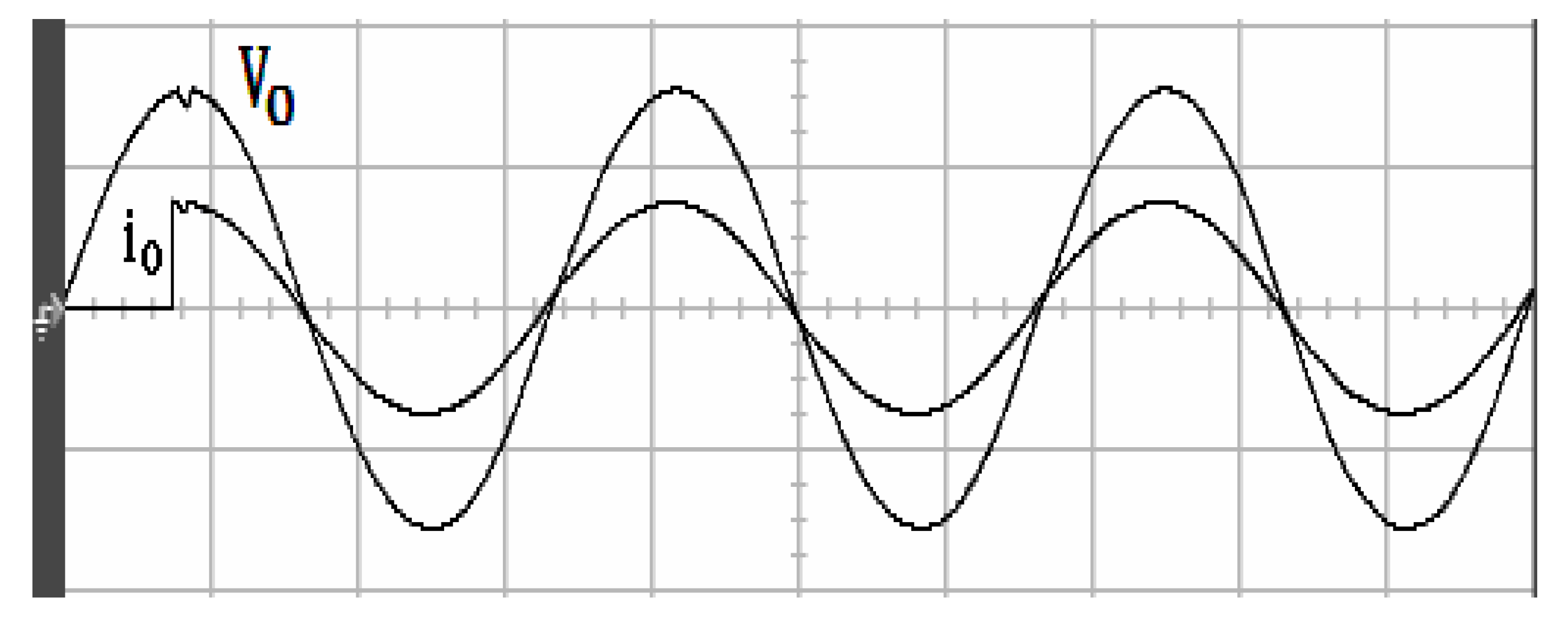
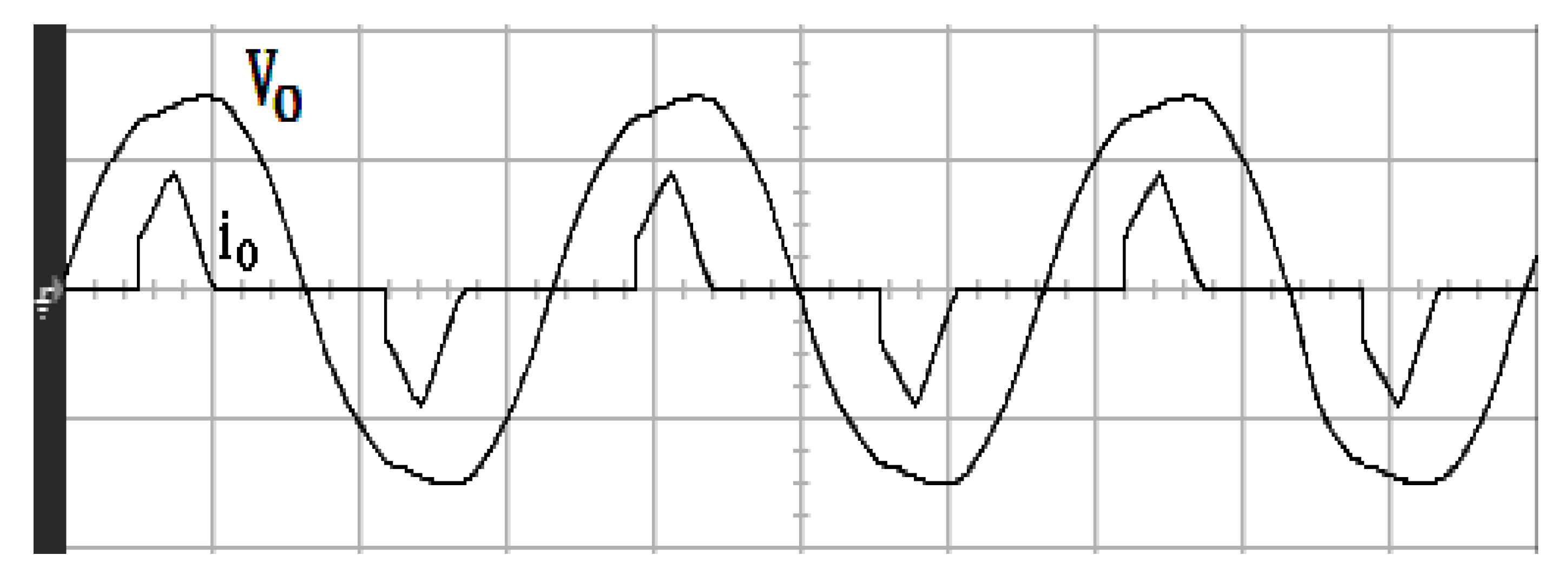
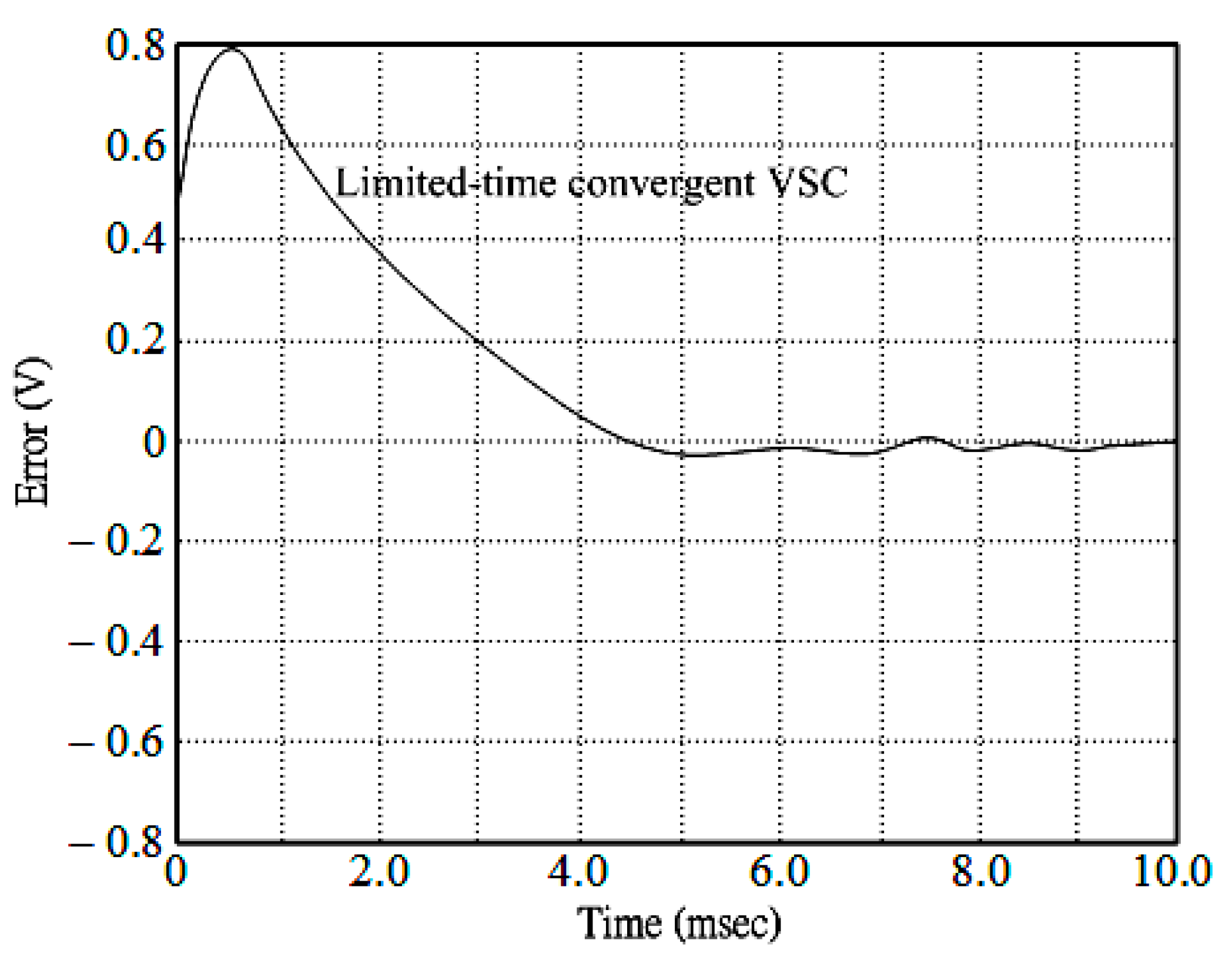
4. Simulations, Experiments, and Discussions

Through simulation and experimental results, this section aims to check the proper performance of the proposed solution. In this regard, the parameters of a single-phase sine-wave inverter are provided as Table 1 and Figure 2 shows the prototype picture.
In Figure 3 and Figure 4, there are no significant distortions found in the simulated output voltages of the conventional limited-time convergent VSC inverter (%THD = 0.06%) and the proposed single-phase sine-wave inverter (%THD = 0.04%) during full loads.
The simulated output waves of the sine-wave inverter with conventional limited-time convergent VSC operating under rectifier-type load situation is graphically observed in Figure 5. Note that this is a distinguishable high %THD value of 18.29%. In Figure 6, a simulation of the output waves of the proposed sine-wave inverter under rectifying load reveals the similar high sharp waves in the current, while the output voltage remains quite similar to the requisite sine wave (0.34% low THD value). It can be concluded that the proposed sine-wave inverter delivers considerably improved stabilization when compared to the conventional limited-time convergent VSC sine-wave inverter for a rectifier-type load condition.
The experimental output waves (%THD = 0.07%) of the conventional limited-time convergent VSC inverter subjected to a resistive load R L = 12   Ω are illustrated in Figure 7. One can view that there is a remarkably close sine wave output voltage. In Figure 8, the proposed solution is applied to the experimental output waveform (%THD = 0.05%) of the sine-wave inverter exposed to a resistive load of R L = 12   Ω . As always, an output-voltage waveform strongly approximates a sine shape.
The output waves of the sine-wave inverter handled by conventional limited-time convergent VSC at 90 ° trigger angle, switching from no load to full load ( R L = 12   Ω ), can be visualized in Figure 9. From the graphs, a major transitory voltage dropping could be detected, which is not sufficiently compensated by the controller. With the proposed solution, an experimental output waveform of the sine-wave inverter operating at 90 ° trigger angle, switching from no load to full load ( R L = 12   Ω ), appears in Figure 10. The little transitory voltage falls and the reversion within a short period of time makes for good compensating capability.
It is shown in Figure 11 that the measured waveform of the conventional limited-time convergent VSC controlled inverter suffices for the similar loading case. One can examine the sinusoidal voltage waveform showing obvious warp distortion and high %THD of 12.11%, which is not ideal for steady-state operation. The measured waveforms of the proposed solution with rectifier type load condition are provided in Figure 12. The output voltage waveform of the proposed converter approximates a sinusoidal shape having a relatively low THD of 0.50%, which excels the IEEE 519-2014 harmonic specification. Table 2 tabulates the percent THD for the output voltage in the converter subjected to abrupt changes in load and rectifier type load.
The tracking tolerances of the conventional limited-time convergent VSC and the proposed solution are each plotted in Figure 13 and Figure 14. In comparison with the conventional limited-time convergent VSC, there is a high degree of accuracy in tracking as well as limited time convergence in the proposed solution.
Based on the above results, we can make a comparative discussion as follows. Previous literatures [43,44,45,46] have shown that conventional VSC used in system design for inverters can achieve good performance, but the overall control objective relies heavily on a single sliding function to obtain the final improvement, which will produce severe distorted waveforms if non-linear loads are encountered. The analog units have realized multiple-loop via the continuous-time VSC method. There is unfortunately a very intricate architecture of physical parts as well as restricted functionality of control. A three-level VSC approach-controlled converter has rendered considerable steady-state performance, yet the temporary phase response is not ideal when exposed to dynamic changes in load. Discrete-time VSC has been used for inverters, and its dynamic characteristics exhibits fine behavior, whereas the steady-state reaction is really weak during non-linear loading. Recent new literatures [47,48,49] have applied various VSC methods with non-linear sliding mode functions to control inverters. The steady-state waveforms with low total harmonic distortion and fast transient response under sudden load changes have been obtained. In spite of the fact that the end effect of the inverter developed in this paper is not superior to the THD effects of these latest works, it is worth noting that the simplified control architecture, time-efficient operation, and theoretical ease of understanding of the proposed solution are far preferable to these recent schemes. Basically, the proposed inverter can be almost directly applied to the uninterruptible power supplies or solar power generation systems in practice. The inverter output power is limited to 1 kw, and future advanced research can develop the three-phase inverter to increase the output power.

5. Conclusions

A QRVSC coupled with BSO used in a single-phase sine-wave inverter controllable on a digital signal processor is described in this paper for the verification of the proposed solution. Instead of typical VSC, the proposed solution merges the strengths of both the QRVSC and BSO. The QRVSC is able to cut down the very lengthy convergence time seen in typical VSC; however, the quick-response variable structure control operated single-phase sine-wave inverter output-voltage continues to deliver undesirable tracking control with a high-level of distorted waveform as well as high-frequency chatter if the control parameters cannot be designed optimally. Assuming that the load is a heavily non-linear ambient (like rectifier loading), the BSO is used to optimize the QRVSC parametric values, which contributes to the cancellation of high-frequency chatter with obtaining a near-AC waveform output. This proposed solution is supported by Lyapunov’s theoretical evidence of closed-loop stability in relation to the finite-time convertibility of the system state, thus creating a high efficient single-phase sine-wave inverter output voltage. The proposed solution has effectively met the IEEE 519-2014 requirement of suppressing voltage harmonics THD values below 5%. Simulations as well as experimental results reveal that it is possible to realize lower total harmonic distortion, speedy transients, and chatter suppression for the proposed controllable single-phase sine-wave inverter subjected to a variety of loading.

Author Contributions

E.-C.C. conceived and investigated the algorithm, designed the circuit, and developed the methodology; H.-L.C., C.-H.C., R.-C.W., H.-W.X., X.-H.C. and Z.-K.X. prepared software resources and set up the simulation software; E.-C.C. performed control system simulations; E.-C.C. carried out experiments, analyzed the results, wrote the paper, and revised it for submission. All authors have read and agreed to the published version of the manuscript.

Funding

This research was funded by the 2021 ISU Research Project, under contract number ISU-110-01-02A. This research was also funded by the Ministry of Science and Technology (MOST) of Taiwan, under contract number MOST 110-2221-E-214-021.

Institutional Review Board Statement

Not applicable.

Informed Consent Statement

Not applicable.

Data Availability Statement

Not applicable.

Acknowledgments

The authors would like to thank the 2021 ISU Research Project (ISU-110-01-02A) and the research project (MOST 110-2221-E-214-021) of the Ministry of Science and Technology (MOST), Taiwan for their support of simulation equipment, experimental materials, and devices.

Conflicts of Interest

The authors declare no conflict of interest.

References

  1. Kumar, V.; Behera, R.K.; Joshi, D.; Bansal, R. Power Electronics, Drives, and Advanced Applications; CRC Press: Boca Raton, FL, USA, 2020. [Google Scholar]
  2. Blaabjerg, F. Control of Power Electronic Converters and Systems; Academic Press: Cambridge, MA, USA, 2018. [Google Scholar]
  3. Wilamowski, B.M.; Irwin, J.D. Power Electronics and Motor Drives; CRC Press: Boca Raton, FL, USA, 2011. [Google Scholar]
  4. Branko, L.D.; Branko, B. Power Electronics: Converters and Regulators; Springer: New York, NY, USA, 2015. [Google Scholar]
  5. Yuriy, R.; Sergey, R.; Evgeny, C.; Pavel, V. Power Electronics Basics: Operating Principles, Design, Formulas, and Applications; CRC Press: Boca Raton, FL, USA, 2016. [Google Scholar]
  6. IEEE Std 519-2014. IEEE Recommended Practice and Requirements for Harmonic Control in Electric Power Systems. In Proceedings of the IEEE Std 519-2014 (Revision of IEEE Std 519-1992), New York, NY, USA, 11 June 2014; pp. 1–29.
  7. Standard EN 50160. Voltage Characteristics of Electricity Supplied by Public Distribution Systems; EN 50160; CENELEC: Brussels, Belgium, 2010. [Google Scholar]
  8. Arunkumar, G.; Dhanamjayulu, C.; Padmanaban, S.; Prusty, B.R.; Khan, B. Implementation of Optimization-Based PI Controller Tuning for Non-Ideal Differential Boost Inverter. IEEE Access 2021, 9, 58677–58688. [Google Scholar] [CrossRef]
  9. Ally, C.Z.; Jong, E.C.W. Robust PI control of a grid-connected voltage source inverter for virtual inertia response in weak grid conditions. In Proceedings of the 2019 International Conference on Smart Energy Systems and Technologies, Porto, Portugal, 9–11 September 2019; pp. 1–6. [Google Scholar]
  10. Ghosh, S.; Moulik, B.; Singh, H.P. Coordinated Converter-Inverter PI based Grid Tied Photovoltaic System. In Proceedings of the 2021 6th International Conference for Convergence in Technology, Maharashtra, India, 2–4 April 2021; pp. 1–7. [Google Scholar]
  11. Hou, H.; Zhang, S.G.; Yang, J.W.; Hu, W.W. Harmonic suppression of LCL grid-connected inverter based on PI control. In Proceedings of the 2021 International Conference on Artificial Intelligence and Electromechanical Automation, Guangzhou, China, 14–16 May 2021; pp. 15–18. [Google Scholar]
  12. Wang, X.Q.; Wang, Z.; Xu, Z.X.; Wang, W.; Wang, B.; Zou, Z.X. Deadbeat Predictive Current Control-Based Fault-Tolerant Scheme for Dual Three-Phase PMSM Drives. IEEE J. Emerg. Sel. Top. Power Electron. 2021, 9, 1591–1604. [Google Scholar] [CrossRef]
  13. Khatib, H.E.; Peña, M.; Grothmann, B.; Gedlu, E.; Saur, M. Flux Observer-Based MTPF/MTPV-Operation with Low Parameter Sensitivity Applying Deadbeat-Direct Torque and Flux Control. IEEE Trans. Ind. Appl. 2021, 57, 2494–2504. [Google Scholar] [CrossRef]
  14. Serrano-Delgado, J.; Mattavelli, P.; Cobreces, S.; Abedini, H.; Rizo, M.; Buso, S.; Bueno, E.J. Output Capacitance Minimization for Converters in DC Microgrids via Multi-Objective Tuning of Droop-Based Controllers. IEEE Access 2020, 8, 222700–222710. [Google Scholar] [CrossRef]
  15. Nicoletti, A.; Martino, M.; Karimi, A. A Robust Data-Driven Controller Design Methodology with Applications to Particle Accelerator Power Converters. IEEE Trans. Control Syst. Technol. 2019, 27, 814–821. [Google Scholar] [CrossRef]
  16. Xie, C.; Liu, D.; Li, K.; Zou, J.X.; Zhou, K.L.; Guerrero, J.M. Passivity-Based Design of Repetitive Controller for LCL-Type Grid-Connected Inverters Suitable for Microgrid Applications. IEEE Trans. Power Electron. 2021, 36, 2420–2431. [Google Scholar] [CrossRef]
  17. Ye, J.; Liu, L.G.; Xu, J.B.; Shen, A.W. Frequency Adaptive Proportional-Repetitive Control for Grid-Connected Inverters. IEEE Trans. Ind. Electron. 2021, 68, 7965–7974. [Google Scholar] [CrossRef]
  18. Steinberger, M.; Horn, M.; Fridman, L. Variable-Structure Systems and Sliding-Mode Control: From Theory to Practice; Springer International Publishing: Cham, Switzerland, 2020. [Google Scholar]
  19. Li, S.; Yu, X.; Fridman, L.; Man, Z.; Wang, X. Advances in Variable Structure Systems and Sliding Mode Control—Theory and Applications; Springer International Publishing: Cham, Switzerland, 2018. [Google Scholar]
  20. Itkis, U. Control Systems of Variable Structure; Wiley: New York, NY, USA, 1976. [Google Scholar]
  21. Utkin, V.I. Variable Structure Systems with Sliding Modes. IEEE Trans. Autom. Control 1977, AC-22, 212–222. [Google Scholar] [CrossRef]
  22. Ahmed, A.A.; Ahmad, R.B.; Yahya, A.; Tahir, H.H.; Quinlan, J. Variable Structure System with Sliding Mode Controller. Procedia Eng. 2013, 53, 441–452. [Google Scholar] [CrossRef]
  23. Chauhan, U.; Singh, V.; Rani, A. PV Fed Sliding Mode controlled SEPIC converter with Single Phase Inverter. In Proceedings of the 2020 5th International Conference on Communication and Electronics Systems, Coimbatore, India, 10–12 June 2020; pp. 20–25. [Google Scholar]
  24. Stefanello, M.; Massing, J.R.; Vieira, R.P. Robust control of a grid-connected converter with an LCL-filter using a combined sliding mode and adaptive controller in a multi-loop framework. In Proceedings of the 2015 41st Annual Conference of the IEEE Industrial Electronics Society, Yokohama, Japan, 9–12 November 2015; pp. 3726–3731. [Google Scholar]
  25. Martins, L.T.; Pinheiro, H.; Stefanello, M.; Vieira, R.P. Sliding mode-based multi-loop current control of a LCL grid-tied converter. In Proceedings of the 2017 IEEE 8th International Symposium on Power Electronics for Distributed Generation Systems, Florianopolis, Brazil, 17–20 April 2017; pp. 1–6. [Google Scholar]
  26. Wang, Y.; Wai, R.J. Design of Discrete-Time Backstepping Sliding-Mode Control for LCL-Type Grid-Connected Inverter. IEEE Access 2020, 8, 95082–95098. [Google Scholar] [CrossRef]
  27. Jung, S.L.; Tzou, Y.Y. Discrete feedforward sliding mode control of a PWM inverter for sinusoidal output waveform synthesis. In Proceedings of the 1994 Power Electronics Specialist Conference, Taipei, Taiwan, 20–25 June 1994; pp. 552–559. [Google Scholar]
  28. Esmaeili, H.; Asadi, M. A Sliding Mode Controller Based on Robust Model Reference Adaptive Proportional-integral Control for Stand-alone Three-phase Inverter. J. Mod. Power Syst. Clean Energy 2021, 9, 668–678. [Google Scholar] [CrossRef]
  29. Ayalew, B.; Yahaya, A.A.; Durra, A.A. Robust Continuous Nonlinear Predictive Controller (CNMPC) via Integral Sliding Mode Control (ISMC) for Grid-Tied PV Inverter. In Proceedings of the 2020 2nd International Conference on Smart Power & Internet Energy Systems, Bangkok, Thailand, 15–18 September 2020; pp. 514–519. [Google Scholar]
  30. Repecho, V.; Biel, D.; Olm, J.M. A Simple Switching-Frequency-Regulated Sliding-Mode Controller for a VSI with a Full Digital Implementation. IEEE J. Emerg. Sel. Top. Power Electron. 2021, 9, 569–579. [Google Scholar] [CrossRef]
  31. Gao, M.; Wang, D.; Li, Y.L.; Yuan, T.Q. Fixed Frequency Pulse-Width Modulation Based Integrated Sliding Mode Controller for Phase-Shifted Full-Bridge Converters. IEEE Access 2018, 6, 2181–2192. [Google Scholar] [CrossRef]
  32. Nair, R.R.; Behera, L.; Kumar, S. Event-Triggered Finite-Time Integral Sliding Mode Controller for Consensus-Based Formation of Multirobot Systems with Disturbances. IEEE Trans. Control Syst. Technol. 2019, 27, 39–47. [Google Scholar] [CrossRef]
  33. Hou, H.Z.; Yu, X.H.; Xu, L.; Rsetam, K.; Cao, Z.W. Finite-Time Continuous Terminal Sliding Mode Control of Servo Motor Systems. IEEE Trans. Ind. Electron. 2020, 67, 5647–5656. [Google Scholar] [CrossRef]
  34. Zak, M. Terminal Attractors for Addressable Memory in Neural Network. Phys. Lett. A 1988, 133, 18–22. [Google Scholar] [CrossRef]
  35. Zou, A.M.K.; Kumar, D.; Hou, Z.G.; Liu, X. Finite-Time Attitude Tracking Control for Spacecraft Using Terminal Sliding Model and Chebyshev Neural Network. IEEE Trans. Syst. Man Cybern. Part B Cybern. 2011, 41, 950–963. [Google Scholar] [CrossRef] [PubMed]
  36. Lu, K.F.; Xia, Y.Q. Finite-Time Fault-Tolerant Control for Rigid Spacecraft with Actuator Saturations. IET Proc.-Control Theory Appl. 2013, 7, 1529–1539. [Google Scholar] [CrossRef]
  37. Shao, K.; Zheng, J.C.; Huang, K.; Wang, H.; Man, Z.H.; Fu, M.Y. Finite-Time Control of a Linear Motor Positioner Using Adaptive Recursive Terminal Sliding Mode. IEEE Trans. Ind. Electron. 2020, 67, 6659–6668. [Google Scholar] [CrossRef]
  38. Cheng, S.; Shi, Y.H. Brain Storm Optimization Algorithms: Concepts, Principles and Applications; Springer International Publishing: Cham, Switzerland, 2019. [Google Scholar]
  39. Xue, X.S.; Lu, J.W. A Compact Brain Storm Algorithm for Matching Ontologies. IEEE Access 2020, 8, 43898–43907. [Google Scholar] [CrossRef]
  40. Jiang, Y.X.; Chen, X.; Zheng, F.C.; Niyato, D.; You, X.H. Brain Storm Optimization-Based Edge Caching in Fog Radio Access Networks. IEEE Trans. Veh. Technol. 2021, 70, 1807–1820. [Google Scholar] [CrossRef]
  41. Wu, C.Y.; Fu, X.S. An Agglomerative Greedy Brain Storm Optimization Algorithm for Solving the TSP. IEEE Access 2020, 8, 201606–201621. [Google Scholar] [CrossRef]
  42. Aldhafeeri, A.; Rahmat-Samii, Y. Brain Storm Optimization for Electromagnetic Applications: Continuous and Discrete. IEEE Trans. Antennas Propag. 2019, 67, 2710–2722. [Google Scholar] [CrossRef]
  43. Jezernik, K.; Zadravec, D. Sliding Mode Controller for a Single Phase Inverter. In Proceedings of the Fifth Annual Applied Power Electronics Conference and Exposition, Los Angeles, CA, USA, 11–16 March 1990; pp. 185–190. [Google Scholar]
  44. Chiang, S.J.; Tai, T.S.; Lee, T.S. Variable Structure Control of UPS Inverters. IEE Proc.-Elect. Power Applicat. 1998, 145, 559–567. [Google Scholar] [CrossRef]
  45. Malesani, L.; Rossetto, L.; Spiazzi, G.; Zuccato, A. An AC Power Supply with Sliding-Mode Control. IEEE Ind. Appl. Mag. 1996, 2, 32–38. [Google Scholar] [CrossRef]
  46. Chan, C.Y. Servo-System with Discrete-Variable Structure Control. Syst. Contr. Lett. 1991, 17, 321–325. [Google Scholar] [CrossRef]
  47. Pandey, A.; Borkar, R.; Kumbhar, S.; Ghunke, P.; Jain, P. Comparison of Power Electronic Converters with Sliding Mode Control and Open Loop Control. In Proceedings of the 2020 International Conference on Convergence to Digital World-Quo Vadis (ICCDW), Mumbai, India, 18–20 February 2020; pp. 1–5. [Google Scholar]
  48. Mehta, A.; Naik, B. Sliding Mode Controllers for Power Electronic Converters; Springer: New York, NY, USA, 2019. [Google Scholar]
  49. Komurcugil, H.; Biricik, S.; Bayhan, S.; Zhang, Z. Sliding Mode Control: Overview of Its Applications in Power Converters. IEEE Ind. Electron. Mag. 2021, 15, 40–49. [Google Scholar] [CrossRef]
Figure 1. Frame diagram relating to a single-phase sine-wave inverter.
Processes 09 02132 g001
Figure 2. Prototype picture of a single-phase sine-wave inverter.
Processes 09 02132 g002
Figure 3. Output voltage and current for simulation of the conventional limited-time convergent VSC at full load (vertical: 50 V/div and 15 A/div).
Processes 09 02132 g003
Figure 4. Output voltage and current for simulation of the proposed solution at full load (vertical: 50 V/div and 15 A/div).
Processes 09 02132 g004
Figure 5. Output voltage and current for simulation of the conventional limited-time convergent VSC under rectifier-type load (vertical: 50 V/div and 25 A/div).
Processes 09 02132 g005
Figure 6. Output voltage and current for simulation of the proposed solution under rectifier-type load (vertical: 50 V/div and 25 A/div).
Processes 09 02132 g006
Figure 7. Output voltage and current for experiment of the conventional limited-time convergent VSC at full load (vertical: 100 V/div and 20 A/div; horizontal: 5 ms/div).
Processes 09 02132 g007
Figure 8. Output voltage and current for experiment of the proposed solution at full load (vertical: 100 V/div and 20 A/div; horizontal: 5 ms/div).
Processes 09 02132 g008
Figure 9. Output voltage and current for experiment of the conventional limited-time convergent VSC from no load to full load (vertical: 100 V/div and 20 A/div; horizontal: 5 ms/div).
Processes 09 02132 g009
Figure 10. Output voltage and current for experiment of the proposed solution from no load to full load (vertical: 100 V/div and 20 A/div; horizontal: 5 ms/div).
Processes 09 02132 g010
Figure 11. Output voltage and current for experiment of the conventional limited-time convergent VSC under rectifier load (vertical: 100 V/div and 25 A/div; horizontal: 5 ms/div).
Processes 09 02132 g011
Figure 12. Output voltage and current for experiment of the proposed solution under rectifier load (vertical: 100 V/div and 25 A/div; horizontal: 5 ms/div).
Processes 09 02132 g012
Figure 13. Convergent speed of tracking error for the conventional limited-time convergent VSC.
Processes 09 02132 g013
Figure 14. Convergent speed of tracking error for the proposed solution.
Processes 09 02132 g014
Table 1. Parameters of the sine-wave inverter with inductor-capacitor filter.
ParametersValues
DC   supply   voltage   ( V d c )205 V
Sine   output   voltage   ( v o )155.56 Vmax
Frequency of sine output voltage60 Hz
Filter   inductor   ( L f )0.2 mH
Filter   capacitor   ( C f ) 30 μF
Resistive   load   ( R L )12 Ω
Switching frequency36 kHz
Table 2. %THD of output voltage.
Conventional Limited-Time Convergent VSC
SimulationRectified load
%THD
18.29%
ExperimentRectified load
%THD
12.11%
Proposed solution
SimulationRectified load
%THD
0.34%
ExperimentRectified load
%THD
0.50%
Publisher’s Note: MDPI stays neutral with regard to jurisdictional claims in published maps and institutional affiliations.

