Article

Modeling and Flowsheet Simulation of Vibrated Fluidized Bed Dryers

1
Institute of Solid Process Engineering and Particle Technology, Hamburg University of Technology, 21073 Hamburg, Germany
2
Tetra Pak CPS, 8448 Heerenveen, The Netherlands
3
Tetra Pak Processing Systems, 86 Lund, Sweden
*
Author to whom correspondence should be addressed.
Current address: Hamburg University of Technology, Institute of Solid Process Engineering and Particle Technology, Denickestrasse 15, 21073 Hamburg, Germany.
These authors contributed equally to this work.
Processes 2021, 9(1), 52; https://doi.org/10.3390/pr9010052
Submission received: 5 December 2020 / Revised: 20 December 2020 / Accepted: 24 December 2020 / Published: 29 December 2020

Abstract

:
Drying in fluidized beds is an important step in the production of powdered materials. Especially in the food and pharmaceutical industry, fluidized bed dryers are often vibrated to improve the drying process. In the current work, a continuous fluidized bed drying model is implemented in the novel, open-source flowsheet simulation framework Dyssol. The new model accounts for the hydrodynamic characteristics of all Geldart groups as well as the impact of mechanical vibration on the drying process. Distributed particle properties are considered by the model. Comprehensive validation of the model was conducted for a wide range of process parameters, different materials, dryer geometries and dimensions as well as the impact of vibration. Particle properties are predicted accurately and represent the broad experimental data well. A sensitivity analysis of the model confirmed grid independence and the validity of underlying model assumptions.

Graphical Abstract

1. Introduction

In industrial production processes, drying of granular materials is a crucial step. The main advantage of fluidized bed dryers compared to other convective dryers is the homogeneity of product temperature and moisture content due to intense mixing of the particles. Furthermore, the higher heat and mass transfer rates allow for efficient drying at moderate conditions, making fluidized bed dryers particularly interesting for heat sensitive products. Thus, fluidized bed dryers are commonly applied in the pharmaceutical and food industry [1].
Sivakumar et al. [2] reviewed common food products dried in fluidized beds. They investigated apple and carrot cubes or slices, rice paddy, wheat grains and soybeans with particle sizes in the millimeter range, belonging to Geldart groups D or B. Many products in the food and pharmaceutical industry are cohesive due to their chemical composition or show small particle sizes (a few micrometers) and/or low densities (i.e., dairy powders, amorphous lactose) [3]. Those are therefore classified as powders of Geldart group A or C. Cohesive forces pose additional challenges in the fluidization of said powders, often resulting in channeling, stagnant regions in the bed or formation of unwanted agglomerates. Additional forces must be introduced to overcome these cohesive effects and improve, or sometimes enable, fluidization. Therefore, mechanical vibration of fluidized bed dryers is commonly used on industrial scale [4,5].
The vibration reduces the minimum fluidization velocity ( u mf ). This allows for drying at reduced gas velocities and increases the efficiency of the drying process. Furthermore, the vibration counteracts cohesive effects, such as van der Waals forces, electrostatic forces and liquid bridges. Therefore, channels and stagnant region in the bed may be resolved and the formation of agglomerates is hindered. Specifically, the reduction of agglomerate size influences the hydrodynamics of fluidization, resulting in reduced amount of gas in form of bubbles and thereby increasing heat and mass transfer rates [4,6]. Additionally, vibration was reported to reduce segregation in fluidized beds of particles with wide size distribution [7].
On industrial scale, fluidized bed dryers are often operated in continuous mode to increase their efficiency. Furthermore, drying processes often include recycle streams at different stages of the process chain (e.g., between spray dryers and fluidized bed dryers). Additionally, combinations of different process unit operations in one drying apparatus is common practice. Examples are combinations of drying, cooling and particle formulation zones in one continuous fluidized bed. All the above result in high complexity with respect to control and modeling of the process [5,8].
Numerical simulations of the drying process can be a powerful tool for the design and optimization of the process and the entire process chain. High detail simulation approaches such as CFD-DEM might be able to represent the real case very closely and thus give the most accurate information about the small-scale interaction of gas and individual particles. However, CFD-DEM approaches are unsuited for large and complex particulate drying processes due to high computational demands [9]. As a result of the complexity and inter-dependency of drying processes, macroscopic approaches such as flowsheet simulation are a more appropriate choice. They use highly efficient shortcut models to account for the most relevant mechanisms and system dynamics. These models can be easily combined to represent complete process chains, which consist of individual process steps with different scales of response time and complexity levels. Therefore, this approach allows for simulation of long time scales and makes it especially interesting for model-based control purposes.
In this work, the novel, open-source flowsheet simulation framework Dyssol is used, which allows for the investigation of dynamic behavior of complex solids processes by providing a framework for model development, flowsheet creation as well as efficient numerical methods. Additionally, a library of predefined models for basic unit operations, such as mixing or splitting, is integrated in Dyssol [10,11].

1.1. Background on Fluidized Bed Modeling

Correct representation of the hydrodynamics, as well as the drying kinetics of fluidized bed dryers is crucial in the model development of the process, regardless of the investigated scale. Established models of fluidized bed hydrodynamics and drying kinetics are introduced in the following chapters. Hereby, the focus lies on the application in flowsheet simulation.

1.1.1. Modeling of Hydrodynamics

The hydrodynamics of fluidized beds are dominated by the formation of gas bubbles and their behavior in the bed. Bubbles in fluidized beds generally grow with increasing bed height due to coalescence and reducing pressure. Particles of different Geldart groups have been shown to cause significant differences in bubble characteristics. Bubbles of Geldart group A powders rise faster than the suspension gas and can reach a maximum bubble size due to an equilibrium between splitting and coalescence, given sufficiently large bed height. Bubbles of Geldart group B are not limited in size and can result in slugging if the bubble size approaches the diameter of the bed. They are also faster than the suspension gas. Bubbles of Geldart group D, however, move slower than the suspension gas. Thus, the suspension gas passes through the bubbles on its way to the bed surface [1].
Different approaches have been developed for the description of hydrodynamics, some if which have been briefly reviewed by Daud [12]. A two-phase model, first introduced by Davidson and Harrison [13], distinguishes between gas in the bubble phase and the suspension phase. It assumes the bubbles to be free of solids and that the particles are only in contact with the suspension gas. A more complex three phase model was introduced by Kunii and Levenspiel [14]. They distinguished between solid-free bubbles, a cloud around the bubbles and a suspension phase with different concentrations of solids [14].
Davidson and Harrison’s two-phase model [13] was further improved and refined by Hilligardt and Werther [15], who introduced semi-empirical correlations to describe the hydrodynamics of fluidized beds of Geldart A, B and D particles. Their model has been successfully applied in the modeling of several fluidized bed processes [16,17,18,19] and has been confirmed to be accurate [20,21,22,23]. Recently, the Hilligardt and Werther model was expanded for modeling the hydrodynamic of cohesive Geldart A and C particles with and without vibration of the fluidized bed [6].

1.1.2. Modeling of Dying Kinetics

The second, crucial part of a fluidized bed drying model is the representation of drying kinetics. In the first drying period, when the particle surface is completely covered with water, only gas properties such as velocity, temperature and inlet humidity determine the drying kinetics. This results in a constant drying rate, which can be described by Fick’s law.
Modeling the second drying period or falling rate period, is much more complex as intraparticle resistances become the rate limiting factors. Intraparticle phenomena are diffusion inside the particle and to the outside, heating of the particle and capillary effects [1]. Several modeling approaches for the drying kinetics of fluidized bed dryers have been proposed and applied in the literature. Kemp and Oakley [24] and Lehmann et al. [25] reviewed these modeling approaches. Two approaches have been identified as most suitable for the application in flowsheet simulation: the Normalized Characteristic Drying Curve (NCDC) and the Reaction Engineering Approach (REA) [25], of which the NCDC is used more often. It was first introduced by van Meel [26] and was refined, adjusted and applied in fluidized bed drying models by several researchers [16,17,18,27,28]. Furthermore, it was successfully applied in the CFD simulation of spray drying of milk [29]. After the NCDC, the material specific drying kinetics ν ˙ is expressed as the ratio of drying rate m ˙ and the drying rate in the first drying period m ˙ 1 .
ν ˙ = m ˙ m ˙ 1
This results in a constant ν ˙ = 1 in the first drying period and a material specific function in the second drying period. The moisture content of the particles is expressed as normalized moisture content ξ using the equilibrium moisture content X eq and the critical moisture content X cr :
ξ = X X eq X cr X eq
The goal of this approach is the expression of drying kinetics independently of process parameters such as gas velocity and temperature. However, the determination of X cr is not always reliable and furthermore the NCDC varies with different measurement methods [30,31]. Burgschweiger et al. [30] measured the NCDC for single particles of γ - Al 2 O 3 with a micro-balance and a drying tunnel and gained significantly different results. This can be explained by different drying conditions in the devices. When the drying is faster due to increased driving force, the critical moisture content is reached earlier, meaning that the rate limiting effect of intraparticle transport mechanisms influence the drying rate earlier. Consequently, the NCDC shows a flatter trend for higher X cr [30]. These findings suggest that the NCDC may not be the ideal approach to account for material specific drying kinetics.
The Reaction Engineering Approach (REA) was first introduced by Chen et al. [32]. Aiming to express the resistance of evaporation of water with an Arrhenius type activation energy term E A . The normalization is achieved by division of the current activation energy with the activation energy in equilibrium state E A , eq :
E A E A , eq = f ( X X eq )
Plotting the REA curve as a function of ( X X eq ) results in a material specific curve, starting at unity for the equilibrium state and reducing exponentially until approaching zero in the first drying period. The material specific REA curves for several food and non-food materials have been reported in the literature [33,34,35]. For more details regarding the REA and its determination, the reader is referred to [31,33,34]. A detailed study of the suitability of the REA for its application in fluidized bed drying was conducted in [25].

1.2. Flowsheet Simulation

Alaathar et al. [18] and Alaathar [36] implemented a steady state flowsheet model for continuous fluidized bed drying in the framework SolidSim. The model is based on the models developed by Tsotsas [27], Groenewold and Tsotsas [16,37], Burgschweiger et al. [30] and Burgschweiger and Tsotsas [17]. Multiple distributed solids properties, such as residence time, particle size, moisture content and temperature, are considered in the model. The drying kinetics are represented via the NCDC, based on single particle drying measurements.
Alaathar’s model has been tested for Geldart D particles, using the model substance γ - Al 2 O 3 . The solid phase is assumed to be ideally mixed, resulting in solid properties which are independent of the position in the bed. The solids properties depend on multi-dimensional distributed parameters such as residence time, particle size, as well as initial values of particle temperature and moisture content. The particle size distribution is assumed constant, i.e., no breakage, agglomeration nor attrition mechanisms are considered [18,36].
The model uses the original Hilligardt and Werther theory [15] to represent the fluidized bed hydrodynamics. Consequently, the gas in the suspension phase is in direct contact with the particles. Thus, allowing for heat and mass transfer due to convection and evaporation between both phases. The bubble phase is assumed to be free of solids. Hence, the bubble phase is considered to be an active bypass, meaning that heat and mass transfer from the particles to the bubbles occurs indirectly through the suspension phase [18,27]. Consequently, the ratio of gas in the bubble phase to the total gas flow is a key parameter of the model. This parameter is called bubble volume fraction ε B . It is calculated using the correlations from Hilligardt and Werther [15].
More recently, Chen et al. [28] published a fluidized bed drying model very similar to Alaathar et al. [18], including optimization for Geldart D particles. Chen et al. [28] refined the prediction of the residence time of the solids by implementing the number of tanks in series. Furthermore, they showed that the fluidized bed drying of γ - Al 2 O 3 of Geldart group D can be modeled accurately by neglecting the solid-free bubble phase and considering the gas only in the suspension phase. Additionally, they were able to measure particle moisture distributions and show good agreement with the model [28].
In the current work, a continuous fluidized bed drying model is implemented in the novel flowsheet simulation framework Dyssol. It is based on the previously mentioned models from Burgschweiger, Alaathar and Chen et al. [17,18,28]. The model is extended by hydrodynamic models for Geldart A, B and C powders according to [6]. A comprehensive validation of the model is presented in Section 4.1, followed by a sensitivity analysis in Section 4.2. Therein, suitable model improvements regarding some of the critical assumptions with respect to the heat and mass transfer inside the fluidized bed are discussed. Experiments and simulations are conducted for different dryer sizes and geometries. Furthermore, the effects of mechanical vibration of fluidized bed dryers is investigated and considered in the new model.

2. Model

The main scope of the presented model is a proper and efficient description of heat and mass transfer mechanisms between particles and drying gas inside a fluidized bed at stationary operation conditions.

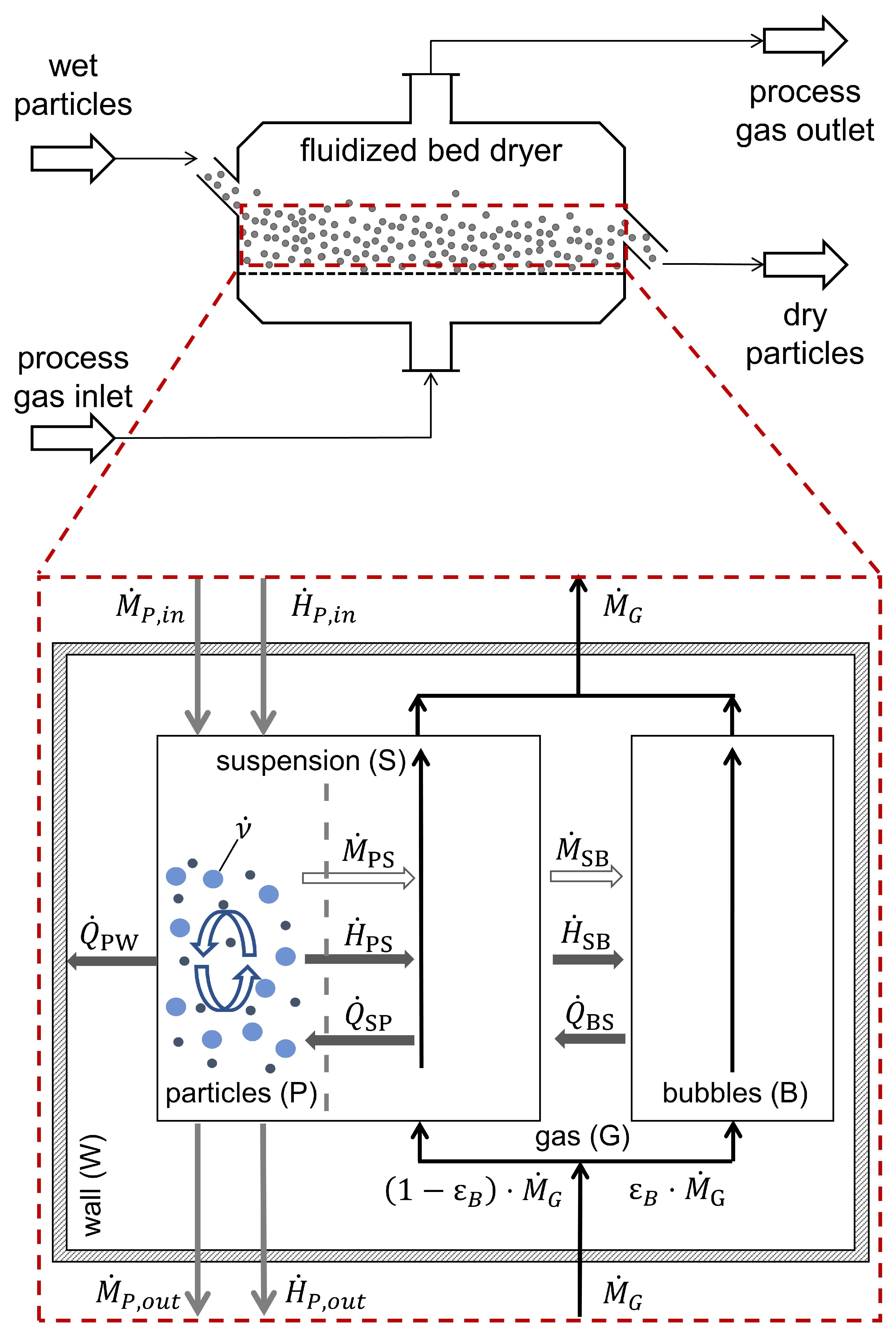
2.1. Structure and Assumptions

Due to the high complexity of the interactions between discrete solid and continuous gas phase, assumptions and simplifications must be made to allow for computation within relevant time frames. Therefore, the gas phase is divided into two distinct phases, namely a suspension phase (S) and a solid-free bubble phase (B). The suspension phase is in direct contact with the particles. Bubbles represent a shortcut stream of fluid through the particle bed that only interacts with the suspension phase. The multi-dimensional nature of the granular particle phase (P) is captured by balancing the distributed particle properties, e.g., particles of different size ( d p ) and initial moisture content ( X 0 ). Due to the high degree of mixing inside the fluidized bed, a spatial independence of the particle properties is assumed [17]. However, the different trajectories of the particles within the fluidized bed lead to a distribution in residence time ( τ ). This influences the resulting moisture content and temperature of the particles at the outlet. The particle size distribution is assumed to be unchanged, analogous to previous models [17,18], i.e., mechanisms such as attrition, agglomeration and entrainment are neglected. Thus, the particle size and the total dry mass of particles stay constant over time. The validity of these assumptions is discussed and confirmed in Section 4.1.5.
The gas phase (bubble and suspension) is assumed to be an ideal gas and to move in plug flow through the bed (PFTR). While moving through the particle bed, the gas temperature and the moisture changes. Therefore, the gas properties depend on the height above the distributor (h).
Figure 1 shows a schematic of the fluidized bed drying model including all heat and mass streams between the distinct model phases.
The main mechanisms captured by the model can be categorized into a hydrodynamics and a thermodynamics part. Both are described in the following chapters. In the hydrodynamics model, the bubble characteristics resulting from the bed material’s Geldart group and the operation conditions are calculated in form of the bubble volume fraction ( ε b ), which is the ratio of gas in bubble phase to gas in suspension phase. The impact of vibration is considered in the hydrodynamics model. The thermodynamic part describes the heat and mass transfer between particles and fluidization gas, taking into account the bubble volume fraction.

2.2. Hydrodynamics Model

The hydrodynamic characteristics of the bed change due to different bubble behavior of the different Geldart groups. In analogy to previous studies [17,18,38], the hydrodynamic model of Hilligardt and Werther [15] is used for particles of Geldart groups A, B and D. In case of cohesive group A (i.e., milk powder) and Geldart group C powders, a modified version of the hydrodynamics model from Hilligardt and Werther is applied [6]. Furthermore, the model accounts for the effects of mechanical vibration on bubble characteristics. For further details and description of the underlying correlations, the reader is referred to [6,15].
Fluidized bed drying experiments with non-cohesive particles of Geldart groups A, B and D showed that mechanical vibration reduced the minimum fluidization velocity ( u mf ). Once the bed was fluidized, no further effects on either hydrodynamics or drying kinetics were evident [25]. Due to the lack of robust correlations in the literature to predict ( u mf ) in dependence of vibration and particle moisture content, experimental values for ( u mf ) from [25] are used as input parameters.

2.3. Thermodynamic Model

As mentioned above, three distinct phases, namely particle (P), suspension (S) and bubble phase (B), are considered in the model. In case of steady state operation, the amount of dry gas does not change over the bed height and the dry particle mass in the bed does not change with varying residence time. Thus, the mass balances of the respective phases only cover the water mass that is transferred between them. For the suspension and bubble phase, the mass and enthalpy balances only depend on the height above the distributor. For the calculation of the gas phase, the normalized height ( ζ = h / H fb ) is used, indicating the current height above the distributor divided by the total bed height. The balances are discretized using the finite volume method and integrals are calculated via the trapezoidal rule.
Suspension phase—water mass balance:
( 1 ε B ) · M ˙ G · d Y S d ζ = ζ M ˙ PS M ˙ SB
Suspension phase—enthalpy balance:
( 1 ε B ) · M ˙ G · d h S d ζ = ζ H ˙ PS + Q ˙ PS H ˙ SB Q ˙ SB
Bubble phase—water mass balance:
ε B · M ˙ G · d Y B d ζ = ζ M ˙ SB
Bubble phase—enthalpy balance:
ε B · M ˙ G · d h B d ζ = ζ H ˙ SB + Q ˙ SB
Depending on the residence time, the particle phase balances describe the water mass and enthalpy of the particles for each size and moisture class. The balances have been deducted from Alathaar [36] and discretized with respect to particle size (d) and moisture content (f), using the method of classes. The discretization regarding residence time was performed in analogy to the gas phases, using the finite volume method.
Particle phase—water mass balance:
M P , d , f · n ( τ ) · d X d , f d τ = 0 1 2 τ ζ M ˙ PS , d , f d ζ
Particle phase—enthalpy balance:
M P , d , f · n ( τ ) · d h d , f d τ = 0 1 2 τ ζ H ˙ PS , d , f + Q ˙ PS , d , f d ζ + τ Q ˙ PW , d , f
The respective transfer streams have been introduced and discussed by Alaathar [36] and are listed together with the respective initial conditions in Appendix A.
Based on the work of Burgschweiger and Tsotsas [17], the residence time dependent number distribution (n) follows from the consideration of steady state conditions in an ideally mixed reactor to:
n ( τ ) = M ˙ P M P exp M ˙ P M P τ , with M ˙ P , out = M ˙ P , in = M ˙ P
As Equation (10) asymptotically approaches zero, the discretization requires the definition of a maximum value for the residence time ( τ m a x ). By default, this value is calculated, such that 99% of the particles are considered, i.e.,
τ m a x = log 1 0.99 M P M ˙ P
The intraparticle resistances in the second drying period are considered by using normalized, material specific drying curves ( ν ˙ ) (see Equation (A2)). The drying curves were derived for the investigated materials in a previous publication, using the inverted REA [25].

2.4. Implementation

The model is implemented in the novel flowsheet framework Dyssol [10]. For the solution of the discretized balances, Dyssol provides an interface for the KINSOL solver from the SUNDIALS package [39]. The solver uses fixed-point iteration with Anderson Acceleration, during which intermediate solution steps are performed and combined with computed weights to find the variable updates for the following iteration [40].
The implemented algorithm is shown schematically in Figure 2. During Initialization the initial values of both model parts are calculated. i.e., the initial bubble diameter and total bed height for the hydrodynamic part are calculated, as well as the gas and particle enthalpies for the thermodynamic part. The latter are based on temperature and moisture content (distributions) of the inlet streams. Material properties, boundary and initial conditions as well as solver parameters are set by the user Parameters in the GUI of Dyssol.
Results from the Hydrodynamic Model consist of the bubble volume fraction ( ε B ), the bubble diameter distribution ( d B , z ) and the total bed height ( H fb ). Comprehensive sensitivity analysis showed very low impact of changes in the hydrodynamics on the model predictions (see Section 4.2). Based on this, and to reduce the simulation time as well as increase the robustness, the hydrodynamics model is calculated only once, and the results are passed on to the Thermodynamic Model. The energy and mass balances of the different phases are solved inside the Thermodynamic Model. Thus, the resulting temperature and moisture content of particles and gas, exiting the fluidized bed, are calculated.
During the Post Processing step, the overall mass and energy balances are calculated to evaluate the given solution and the results are plotted for further analysis.

3. Materials and Methods

For the validation of the proposed fluidized bed drying model, particles of different Geldart groups are investigated in different dryer sizes and geometries, with and without mechanical vibration.

3.1. Materials

Industrial FCC catalyst (Geldart A), Cellets (Geldart B) and γ - Al 2 O 3 (Geldart D) are investigated experimentally and used for validation of the model. The material properties of the dry powders are listed in Table 1. The particle size distribution and sphericity are measured with a Camsizer XT (Retsch). The skeletal density is measured via Helium pycnometry (MultiVolume Pycnometer by Micromeritics). The apparent density is measured by dispersing particles in a measurement cylinder filled with Glycerol ( > 99.5 % p.a. water free) and measuring the change of mass and volume [25]. Additionally, knowledge of the equilibrium moisture content of the materials at given conditions (temperature and relative humidity) is crucial for the prediction of the drying process. Thus, ad- and desorption isotherms are measured in a DVS (Dynamic Vapor Sorption) system by Surface Measurement Systems. The isotherms are measured for a range of temperatures (25, 40 and 60 C). The relevant desorption isotherms are shown in Figure A1. The desorption isotherms are included in the material data base of Dyssol and used in the simulations. The minimum fluidization velocity ( u mf ) for the used FCC catalyst was previously determined in dependence of vibration and particle moisture content [25]. The same procedure was used for the Cellets in this work. The results are shown in Figure A2. The investigated vibration parameters are listed in Table A1.

3.2. Drying Experiments

The drying experiments are conducted in two continuously operated fluidized bed dryers, a lab-scale dryer (GF3 by Glatt GmbH) and a custom-built fluidized bed dryer on pilot-plant-scale. Both dryers were previously used for investigations of fluidized bed drying kinetics of the same materials [25].
The custom-built fluidized bed dryer is operated with and without mechanical vibration (VFB dryer). A simplified flow chart including the most relevant measurement locations is shown in Figure 3. The process chamber measures 500 by 250 mm and has a height of two meters. An expansion zone is installed on top. The bed height during operation is measured with a ruler through the transparent front wall of the dryer. Mechanical vibration is introduced via two synchronized eccentric motors mounted to the bottom of the windbox. Due to the orientation of the motors, strictly vertical vibration is imposed on the dryer. The vibration frequency is controlled with a frequency converter. The amplitude of vibration result from the set frequency, the number and strength of the springs, the VFB dryer is suspended on.
Dried, pressurized air is used as fluidization air for superficial gas velocities up to 0.3 m / s . In this case, the volume flow rate is set with mass flow controllers. For higher gas flow rates (up to 0.6 m / s ), a rotary blower is used, the dryer is operated with ambient air and the flow rate is measured via an orifice plate. In either case, the relative humidity and temperature of the process air are measured before the heater as well as at the entrance of the windbox and at the exit of the drying chamber. Particle and gas temperatures are measured with PT100 thermometers at several positions inside and above the bed. Data acquisition is conducted in LabView. A more detailed description of the installed measurement equipment is given in previous publications [6,25].
The wet feed is stored in a bunker and is transported into the dryer via a rotary valve. The product exits the dryer on the opposite side after passing an outflow hole and is collected in a container. The outflow hole measures 3 cm in diameter and its height can be varied between 8 and 16 cm above the distributor. The entire plant is sealed to the environment to prevent unwanted leakage of particles or air. Entrained material is recovered in a cyclone and fed back into the dryer.
The lab-scale GF3 is operated in continuous mode, as previously performed by Alaathar et al. [18]. A simplified flow chart including the most relevant measurement locations is shown in Figure 4. The conical drying chamber has a diameter of 180 mm at the distributor plate and 250 mm at the top (320 mm above the distributor). An expansion zone with internal filters is located above the drying chamber. Particles are fed into the dryer via a vibrating chute and leave the dryer through an outflow hole, measuring 3 cm in diameter, in the dryer wall. The height of the outflow hole can be adjusted. Outlet heights of 7 and 12 cm are investigated. The bed height during operation is measured with a ruler through a window in the dryer. A detailed description of the setup is given in [36].
Regardless of the used dryer, the particles are mixed with demineralized water before each experiment to reach the desired moisture content. Visual observation of the mixing suggested uniform mixing after approximately 5 min. To ensure uniform mixing and to achieve a narrow moisture distribution, particles are mixed for at least 10 min. The moisture content of feed and dried product is measured with a thermogravimetric moisture analyzer EM 120-HR (Precisa). Therefore, samples are heated to 105 C and the weight is monitored. The weight loss over time is attributed to evaporated water. Thus, the initial moisture content of the sample is determined. The particle mass flow is measured by weighting the product leaving the dryers in regular time intervals.
Parameter studies of continuous fluidized bed drying are conducted in both dryers under steady state conditions. An overview of the applied parameter combinations for validation of the model is given in Table 2.

4. Results and Discussion

Comprehensive validation of the new model is conducted by comparing experimental results with model predictions. The validation is performed for the different fluidized bed dryers and materials, introduced in Section 3, and discussed in the following chapters. Subsequently, a sensitivity analysis of the model is discussed.

4.1. Validation

First, the model is validated for Geldart D and B in the lab-scale dryer. Then, the model predictions are tested for a different dryer size and geometry. In a third validation step, vibration is investigated as an additional process parameter. For the final stage of the validation, Geldart A particles are investigated in the VFB dryer. The experimental and simulation results, used for validation, are summarized in Table A2. Particle temperature and moisture content were measured for the bulk of the samples. For comparison with experimental results, the calculated moisture and temperature distributions were averaged over all particle classes, using the mass weighted average.
The calculation of heat transfer from the dryer to the environment requires accurate determination of the heat transfer resistances of the dryer’s walls and possible thermal insulation. These may vary significantly for different dryers. It may even vary for different areas of a single dryer, depending on the degree of insulation at different parts (e.g., windbox, drying chamber, free board and pipes). To allow for a more general application of the model, another approach is implemented (see Equation (A10)). The heat transfer from the drying chamber to the environment is approximated by calculation of the heat transfer from the particles to the walls of the drying chamber. In this approach, the temperature of the inside of the wall of the dryer needs to be known and is considered in the model as an input parameter. As the dryers used in the experiments are not equipped for the measurement of wall temperatures, said wall temperature would be based on assumptions. The drying temperatures, investigated in this work, do not exceed 80 C . The influence of heat transfer from the bed to the environment will increase with higher drying temperatures. Thus, the influence of heat transfer from the dryer to the environment may be expected to be minor. Consequently, heat transfer between particles and dryer wall (representing heat loss from the dryer to the environment) is not considered in the simulations used for the general model validation. The validity of this assumption is discussed in the following chapters.

4.1.1. Validation for Geldart D Particles

In the first validation step, the model is compared to experiments conducted in the GF3 lab-scale dryer. The gas temperature and the height of the outflow hole were varied. Since the GF3 dryer was operated with ambient air, the inlet moisture content of air ( Y in ) could not be influenced. Furthermore, inlet moisture content ( X P , in ) and particle mass flow ( M ˙ P , dry ) were varied. The hydrodynamics model is validated by comparison of predicted bed height and measured values. Bed heights, derived from simulations and experiments, are plotted against drying temperature and shown in Figure 5. All predicted bed heights lie within the experimental uncertainty, confirming high accuracy of the predictions by the hydrodynamic model. The measured bed heights are lower than the outlet height. This may be explained by the bubbling character of the fluidized bed. As particles are thrown upwards by bubbles erupting at the bed surface. Some of these particles leave the dryer through the outlet hole, resulting in bed heights lower than the outflow hole.
The overall drying model (hydrodynamics and thermodynamic models) is validated via the resulting particle temperature ( T P ) and moisture content ( X P ). Due to variations in ambient air conditions, in particular inlet moisture content of air ( Y in ), the comparison of experimental and simulation data is visualized in three-dimensional plots. In Figure 6 and Figure 7, T P and X P are plotted against drying temperature and inlet moisture content of drying air, respectively.
Figure 6 shows the particle temperature of model predictions and measurements for different process conditions. Increasing drying temperature has the most dominant influence on the particle temperature. Comparison of GF3_A_04 and GF3_A_05 shows that the particle temperature is not affected by the inlet moisture content of drying air, when ratios of particle mass flow and particle inlet moisture content are similar. Both observations are physically founded. In case of experiment GF3_C_02, the particles are still in the first drying period. Consequently, the particle temperature equals the wet bulb temperature of the drying air, which was measured as predicted by the model.
Figure 7 shows the expected trend of increased particle moisture content at the outlet for increased inlet particle mass flow (GF3_A_02). In this case, the combination of higher particle mass flow and higher particle inlet moisture content outweighed the effect of reduced particle moisture content with increased drying temperature, which is evident in all other cases shown in Figure 7. Furthermore, decreased particle moisture content is evident for lower moisture content of inlet air in experiments and simulations alike. All model predictions of particle moisture content show high accuracy for different drying temperatures, moisture contents of inlet air, bed heights as well as particle mass flow rates. Deviations between model predictions and measurements of X P all lie within the margin of error of the experiments. The maximum relative deviation between model and experiment is approximately 15% in case of the lowest drying temperature, inlet moisture content of air and particles (GF3_A_01). In all other cases, relative deviations are below 6%.
In general, measurements and predictions of particle temperature show good agreement (see Figure 6). Relative deviations are less than 4% in all cases. The largest deviation between experiments and simulations are observed at the highest investigated drying temperature (80 C ), which lie just outside the range of measurement errors (indicated by light red planes). Here, the model slightly over-predicts the measurement. The most likely reason for this, lies in the fact that heat transfer between dryer and environment was not considered in the simulations.
Considering heat transfer between particles and dryer wall and optimizing the model predictions by adjusting the assumed wall temperature is likely to result in more accurate predictions. However, use of case specific fitting parameters would impede the comparability of the model to other cases (e.g., other conditions, dryer geometries or materials). This topic is discussed in Section 4.2.1.
The comparison of measurements and model predictions shows that the model represents the physical effects of the investigated process parameters on the particle properties accurately for Geldart D particles.

4.1.2. Validation for Geldart B Particles

Validation of the model for Cellets (Geldart group B) is topic of this chapter. Comparisons of measured and predicted bed heights during the operation for varying superficial gas velocity (u) are shown in Figure 8. For higher gas velocities, the bed expansion increases. In all cases, the height of the outflow hole was fixed at 11.5 cm. As observed and explained above, the bed heights are lower than the height of the outlet hole. The difference between height of the outflow hole and bed height is more pronounced for Geldart B particles because bubbles are more dominant than in beds of Geldart D particles. This effect is represented successfully by the model, as predicted bed heights lie within the measurement errors in all investigated cases. Thus, high accuracy of the hydrodynamics model for Geldart B particles is confirmed.
Figure 9 shows the comparison of measured and predicted particle moisture content for varied drying temperature and inlet moisture content of drying air. The model predictions lie well within the experimental margin of error. Furthermore, reduction of particle moisture content for lower air inlet moisture content and higher temperature of drying air is evident in experiments as well as simulations. Thus, expected trends are confirmed.
Predicted and measured particle temperatures are plotted against drying temperature and inlet moisture content of drying air in Figure 10. Increased drying temperature results in increased particle temperature, whereas the inlet moisture content of the air has no significant impact on the particle temperature. Relative deviations between model predictions and measurements are well below 3%.
Hence, the proposed model accurately predicts particle properties of the investigated Geldart B particles in the examined range of process conditions.

4.1.3. Validation for Dryer Geometries and Vibration

To investigate the influence of vibration on the hydrodynamics and drying kinetics, the VFB pilot-plant-scale dryer was used. In contrast to the GF3 lab-scale dryer, it has a rectangular cross-sectional area. This also allows for a comparison of model performance for different dryer geometries. Consequently, Cellets particles were investigated in the VFB pilot-plant-scale dryer. The validation results are plotted in analogy to the previous chapters.
Figure 11 shows measurements and predictions of bed height for different vibration intensities. Model predictions agree well with experimental data in all cases. No significant influence of vibration on the bed height is observed. This observation is in accordance with previous findings [25]. It was shown that mechanical vibration in the investigated range (low vibration frequencies) reduced u mf . However, no further significant effect on the hydrodynamics was observed for the investigated material [25]. Since correlations for u mf in dependence of moisture content and vibration are not available in the literature, the measured u mf values are used as input parameters in the model. With this, the model can predict the hydrodynamics of the vibrated and un-vibrated fluidized bed within the experimental margin of error.
Comparison of simulated and measured particle moisture content is shown in Figure 12. Gas flow rate, particle mass flow and vibration intensity were varied. Increasing drying temperature leads to reduced particle moisture content. The experimental margin of error could be reduced, compared to experiments in the GF3 dryer due to use of a rotary valve for control of particle mass flow rate. This also reduced the relative deviations between experiments and simulations to values below 14%. Hence, showing the highest accuracy of all validation cases.
Model predictions and measurements of particle temperature are compared in Figure 13. The same trends and dependencies of particle temperature are observed, as in the GF3 dryer. Relative deviations between model and experiment never exceed 2%, indicating accurate predictions. Predicted particle temperatures for low drying temperatures (40 C ) lie within the experimental margin of error. For increasing drying temperatures, the model slightly over-predicts the particle temperature. The same observation is made in the GF3 lab-scale dryer for γ - Al 2 O 3 particles. Likewise, the increased influence of heat transfer from bed to environment may explain this observation. Due to the rectangular geometry of the VFB dryer, the ratio of surface area to volume is larger than in the conical GF3 dryer. Thus, the available heat transfer area is larger and heat transfer rates from particles to the environment increase. Consequently, heat loss from the bed material to the environment is more dominant in the VFB dryer.
Nonetheless, the particle temperature and moisture content could be predicted by the model for different dryer geometries. Case specific optimizations of the model are discussed in Section 4.2.1. The influence of vibration is covered by consideration of reduced u mf of the particles in the model. Model predictions with and without vibration show the same accuracy, when compared to measurements.

4.1.4. Validation for Geldart A

Fluidization of FCC catalyst requires lower gas flow rates than the other investigated powders. Thus, dried pressurized air was used. The inlet moisture content of drying air was constant at approximately 1 g/kg. During the experiments, FCC particles adhered to the walls of the dryer. Thus, a higher degree of uncertainty was added to the optical measurement of bed heights, resulting in higher error margin compared to other investigated powders. Figure 14 shows comparisons of predicted and measured bed height of FCC catalyst in the VFB dryer for varied particle mass flow ( M ˙ P , in ). It is evident that the model predicted slightly lower bed heights than observed in the experiments. Nonetheless, measurements and model predictions agreed reasonably well, i.e., just within the margin of error of the experiments.
Heat transfer from particles to dryer walls needs to be considered in the case of FCC catalyst. This is based on the influence of particle size on the heat transfer coefficient between particles and walls or immersed surfaces, reported by Martin [41]. Approximately five-fold increase of the heat transfer coefficient was observed when particle sizes decreased from the range of the used Geldart B and D particles to the size range of the FCC catalyst [41]. Also, the fact that the VFB dryer has a higher wall area per volume than the GF3 dryer, supports the necessity to consider heat transfer between particles and dryer wall. This is confirmed by simulations with FCC catalyst. When heat transfer between particles and dryer wall was neglected, the particle temperature was strongly over-predicted while the particle moisture content was under-predicted in all cases. Consideration of heat transfer between particles and dryer walls results in much better agreement of model predictions and experiments. Therein, the assumption is made that the wall temperature at the inside of the dryer equals ambient temperature.
Drying temperature and inlet moisture content of drying air were kept constant in the experiments. Thus, the results of the validation are plotted with respect to particle mass flow ( M ˙ P , in ) and inlet moisture content of the particles ( X P , in ). Figure 15 shows the comparison of measured and predicted particle moisture content. Figure 16 compares particle temperature simulations and measurements. In both cases, the model predictions lie well within the experimental margin of error. Expected trends are observed and predicted by the model, namely reduced particle mass flow rate and inlet moisture content results in lower particle moisture content. Likewise, increased particle mass flow rate leads to reduced particle temperature.
It may be concluded that the proposed model is able to predict the fluidized bed drying of FCC catalyst (Geldart group A), when heat transfer between particles and dryer wall is considered. Assuming that the wall temperature equals ambient temperature is a valid approximation in this case, because the VFB dryer is not thermally insulated. Consideration of heat transfer between particles and dryer wall is covered in more detail in Section 4.2.1.

4.1.5. Validation of Model Assumptions

Underlying assumption of the model were introduced in Section 2.1. Changes in particle size, i.e., agglomeration, attrition or entrainment, are neglected. The validity of these assumptions is evaluated in this section.
Visual observation of the particle flow at the inlet and outlet as well as the freeboard showed neither agglomerates nor dust formation during the experiments for Cellets and g a m m a - Al 2 O 3 . Only free flowing primary particles were observed. Measurement of the particle size at the inlet and outlet would not elucidate if particles were temporarily agglomerated or not, because any additional mechanical stress, e.g., taking of samples, transport or pouring material into the Camsizer would most likely break possible liquid bridges and counteract other cohesive forces. Hence temporarily formed agglomerates could not be detected. The formation permanent material bridges can be excluded because the investigated particles are insoluble in water and demineralized water was used in all experiments.
Furthermore, the particle size distribution of the material was measured before and after a day of experiments (2 to 3 drying experiments were performed per day). These measurements showed changes in Sauter diameter in the sub-micrometer range. The size distributions were plotted and showed almost perfect overlap.
Based on these observations, the underlying assumption are confirmed to be valid for the investigated materials and process conditions. The high accuracy of the model predictions also supports this conclusion.

4.2. Sensitivity Analysis

For sensitivity analysis of the model, two reference cases were used (GF3_A_02 and GF3_C_03). Therefore, one parameter increased and decreased around the reference value while all other parameters stayed unchanged. An overview of the simulation parameters of the reference cases is given in Table 3. Special focus lies on the underlying assumptions made in the model development and previous applications of those correlations.
The number of height classes and residence time classes represent the numerical grid of the simulations. The results are not affected by them, as long as the number of residence time classes is >100 and the number of height classes >50. The impact of the cut off residence time value τ max (see Section 2.3) is more pronounced. The lower τ max , the more residence time classes are excluded from the calculations. As particles with the highest residence time will be closest to the equilibrium state, this leads to an increase in particle moisture content and a decrease in particle temperature. Detailed analysis shows that the model predictions lie within the experimental margin of error for τ max > 90%. It must mentioned that an increase in grid refinement as well as τ max leads to significant increase in computation time.
Parameters that influence the hydrodynamics of the fluidized bed are the Geldart group and u mf . The choice of the Geldart group defines the used correlations and parameters for calculation of the bubble volume fraction ( ε B ). The detailed sets of equations are described in [6,15]. A higher bubble volume fraction results in a smaller portion of gas in direct contact with the particles. Consequently, heat and mass transfer rates are reduced between them, which leads to higher particle moisture contents and lower particle temperatures. However, the overall effect of this is only marginal, i.e., results still lie within the experimental margin of error. Also, negligible impact on the overall results is observed for variation of u mf , which is used in the calculation of bubble volume fraction and bed height as well.
The inlet temperature of the particles ( T P , in ) is the process parameter with the lowest impact on the simulation results. As long as T P , in is below the wet bulb temperature, its influence is negligible. For T P , in higher than the wet bulb temperature, the influence becomes more dominant, leading to reduced particle moisture content and increased particle temperature.
As observed and described in the literature [25] as well as in our experiments, the vibration has negligible or no influence on the drying kinetics of the investigated particles. This is represented by the model, which consequently shows negligible sensitivity with respect to vibration frequencies and amplitudes in the investigated ranges. The vibration parameters were chosen similar to industrial applications [6].
Parameters, the model is most sensitive to, are the process parameters discussed in detail during the model validation. It was shown above that the high sensitivity of the model is founded on physical effects and confirmed by experiments (see Section 4.1).

4.2.1. Heat Transfer between Particles and Dryer Wall

Another aspect of the model that has significant influence on the results, is the consideration of heat transfer from particles to the environment through the dryer walls. Therefore, the temperature of the inside of the dryer wall ( T w ) needs to be estimated or assumed. For this sensitivity study, wall temperatures ranging from 10 C –50 C are assumed. The results are heavily affected by this. For T w below ambient conditions, particle moisture content increases and particle temperature decreases strongly. When T w is well above ambient conditions, the particles are much drier, and temperature increases significantly. These trends are to be expected due to high energy sink or source added to the process, respectively. Potential use of this feature are processes with heated dryer wall or internals as extra heat sources.
As mentioned above, deviations between measured and simulated particle temperature at high drying temperatures of Geldart B and D particles may be explained by not considering heat transfer between the dryer and the environment. The exact temperature of the inside of the dryer wall is unknown, thus it is assumed to have ambient temperature in a first step. This assumption includes the consideration of heat conduction through the dryer wall without thermal insulation. Furthermore, heat transfer resistance from the outside of the dryer wall to the ambient air is also neglected.
The influence of heat transfer between particles and dryer wall is shown exemplary for Cellets in the VFB dryer in Figure 17 and compared to experiments. The wall temperature was set to ambient temperature of the respective experiment. The results show that predicted particle temperatures are closer to measured values, when heat transfer between particles and dryer wall is considered.
Assuming that the wall temperature inside the dryer equals ambient temperature is just an estimation of the currently investigated cases. In fact, heat transfer from the dryer wall to the ambient air is subject to resistance. Thus, the wall temperature at the inside of the dryer will be slightly higher than ambient temperature due to transfer resistances, i.e., heat conduction through the wall and heat transfer from the outside of the wall ambient air. Consequently, the temperature of the inside of the dryer wall must be slightly higher than ambient temperature which in turn would results in slightly higher particle temperatures than predicted. As mentioned earlier, the discussed deviations between model and experiment are not significant in the considered range of drying temperature for Geldart B and D particles. However, if higher drying temperatures are of interest, detailed knowledge of the wall temperature of the dryer is needed. A further increase in accuracy could be achieved by consideration of heat transfer from the drying air to the environment via convection or heat transfer via radiation.
For particles with smaller diameters (Geldart A), heat transfer between particles and dryer wall has significant influence and cannot be neglected (see Section 4.1.4).

4.2.2. Number of Transfer Units

Another assumption, made in the model, is that the number of transfer units between bubbles and suspension phase ( N T U SB ) equals 1 at a bed height of 5 cm. Based on this, the heat transfer coefficient between bubbles and suspension ( β SB ) is calculated.
β SB = N T U SB · M ˙ G ρ G · A SB with : N T U SB = H fb 0.05 m
Theoretical limits of the number of transfer units are N T U SB = 0 (inactive bypass, i.e., no mass transfer from suspension to bubble phase) and N T U SB (no bypass, i.e., no resistance to mass transfer between suspension and bubble phase) [37].
The assumption that N T U SB = 1 at H fb = 0.05 m was used in preceding versions of this model ([17,18,36,38]). The assumption was introduced by Groenewold and Tsotsas [16]. They stated that overall drying kinetics were dominated by the mass transfer between particles and suspension gas. Drying kinetics were less sensitive towards mass transfer between bubbles and suspension [37]. This assumption seems to be valid, as its use in previous fluidized bed drying models delivered accurate results [17,18,36,38].
Most values for N T U SB , reported in the literature for fluidized bed applications, vary from 0.01–100 [37]. N T U SB depends on the bubble characteristics and thereby also on particle properties (i.e., Geldart group). Clear dependencies on Reynolds number or bed height have not been identified [37]. The values for N T U SB , used in the validation cases of this work (Section 4.1), varied from 1.36–2.6, under the assumption N T U SB = 1 at H fb = 0.05 m . Considering that particles of different Geldart groups were used in this work and that N T U SB values two orders of magnitude higher or lower may still be valid for fluidized beds, the height, at which N T U SB = 1 may be viewed as a fitting parameter in the model.
Sensitivity analysis of the model regarding N T U SB for reference case GF3_A_02 are plotted in Figure 18. It shows that the original assumption of N T U SB = 1 at H fb = 0.05 m results in good agreement with the experiment for both particle moisture content and temperature. Further increase of N T U SB leads only to minor changes and approaches constant values of the predicted particle properties. These values agree slightly better with the experiments. Higher N T U SB negate the effect of bubbles acting as bypass. These observations support the conclusion of Chen et al. [28] that the bubble phase has negligible effect on the drying kinetics in fluidized beds of Geldart group D particles and that the gas may be considered to be one phase. On the other hand, when N T U SB is reduced, the model predictions are sensitive towards the changes and deviate strongly from the experiments. However, lower values for N T U SB are unreasonable for Geldart group D particles, due to the general low bypass effect of the bubbles. As bubbles in fluidized beds of Geldart group D rise slower than the suspension gas, the suspension gas travels through those bubbles which results in (almost) ideal heat and mass transfer between the two phases [28].
Bubbles of Geldart A and B particles travel faster than the suspension gas. Therefore, the bypass effect of the bubbles is more pronounced than for Geldart D particles [1]. This observation is confirmed by the results of our sensitivity analysis of predicted particle temperature and moisture content of Cellet particles in the GF3 dryer. This is plotted in Figure 19. The particle temperature is affected strongly by increase or decrease of N T U SB alike. The impact of N T U SB on particle moisture content is similar as observed in the example of Geldart D particles, i.e., it has less influence for higher N T U SB but strong influence for reduced N T U SB . Considering the agreement of particle temperature and moisture content with experimental data, the original assumption of N T U SB = 1 at H fb = 0.05 m is confirmed to deliver accurate model predictions in the investigated cases.
All simulations for validation and sensitivity analysis were conducted on a regular PC (Windows 10 Pro x64, 16 GB RAM, Intel Core i7-6700). The duration of the simulations varied between 1 and 3 min.

5. Conclusions

A comprehensive flowsheet simulation model for the steady state of continuously operated fluidized bed dryers was proposed and tested by comparison of model results and experimental investigations. The model was implemented in the open-source flowsheet simulation framework Dyssol. Like its predecessors [17,18], the model was validated for Geldart group D particles. Novel aspects are the confirmed applicability of the model for particles of Geldart groups A and B as well as different dryer geometries. Predictions of hydrodynamic parameters as well as resulting particle properties agreed well with experimental data. Additionally, mechanical vibration of the fluidized bed is considered in the model. During experiments, vibration had little impact on the hydrodynamics and drying kinetics for the investigated materials and range of process parameters. This was expected due to the non-cohesive nature of the investigated particles and was predicted accurately by the model.
Furthermore, sensitivity analyses were conducted. Therefore, independence of grid refinement was proven. The model showed little sensitivity towards hydrodynamic parameters. The strongest impact on the model results was observed for changes in process parameters, namely temperature and inlet moisture content of the drying air, mass flow rate of wet particles and drying air as well as particle inlet moisture content. The same degrees of sensitivity were observed in the experiments and were predicted by the model in a precise manner.
The model was developed and tested for drying conditions typical in pharmaceutical and food applications (maximum drying temperatures of 80 C ), and confirmed to deliver reliable results.
Furthermore, correlations for the hydrodynamics of Geldart C and cohesive Geldart A powders (e.g., milk powders) were implemented in the model. Validation of the model with continuous fluidized bed drying experiments for cohesive powders, when the impact of vibration is more pronounced, is topic of future research. Also, the implemented option of heat transfer between particles and surfaces e.g., dryer walls or internals, requires further validation.

Author Contributions

Conceptualization, S.E.L., M.B., A.J., F.I. and S.H.; methodology, S.E.L. and M.B.; software, M.B.; validation, S.E.L. and M.B.; formal analysis, S.E.L. and M.B.; investigation, S.E.L.; resources, S.H.; data curation, S.E.L. and M.B.; writing—original draft preparation, S.E.L. and M.B.; writing—review and editing, S.E.L., M.B., A.J., F.I. and S.H.; visualization, S.E.L.; supervision, A.J., F.I. and S.H.; project administration, A.J., F.I. and S.H. All authors have read and agreed to the published version of the manuscript.

Funding

This research received no external funding.

Institutional Review Board Statement

Not applicable.

Informed Consent Statement

Not applicable.

Data Availability Statement

The key data are included in the tables of this manuscript. More detailed data (e.g., simulation configuration files) are available on request from the corresponding author.

Acknowledgments

This paper is dedicated to the memory of our late colleague -Ing. Ernst-Ulrich Hartge.

Conflicts of Interest

The authors declare no conflict of interest.

Abbreviations

Roman letters
Atransfer surface aream2
A v i b amplitude of vibrationm
CSTRcontinuous stirred tank reactor-
CFDcomputational fluid dynamics-
c p heat capacity J /kg−1/k−1
ddiameterm
DEMdiscrete element modeling-
Δ E V activation energy J
Δ h V evaporation enthalpy J /kg−1
ffrequency of vibrationHz
FCCfluid catalytic cracking-
ggravitational acceleration m /s−2 2
hspecific enthalpy J /kg−1
Hheightm
H ˙ enthalpy flowW
nnumber density distribution of residence time-
m ˙ mass flux k g /s−1/m−2 2
Mmass k g
M ˙ mass flow k g /s−1
NCDCNormalized Characteristic Drying Curve-
NTUnumber of transfer units-
PFTRplug flow tank reactor-
Q ˙ heat flow W
REAReaction Engineering Approach-
Ttemperature K
ugas velocity m /s−1
VFBvibrated fluidized bed-
Xmoisture content of solids k g /kg−1
Ygas moisture content k g /kg−1
Greek symbols
α heat transfer coefficient J /kg−1/k−1
β mass transfer coefficient m /s−1
ε bed porosity -
ζ normalized bed height -
Λ vibration intensity -
ν ˙ material specific drying curve -
ξ normalized moisture content -
ρ density k g /m−3
τ residence time s
φ relative humidity -
Subscripts
ambambient
Bbubble phase
ddiscretized particle size class
crcritical
eqequilibrium
expexperiment
fdiscretized particle moisture class
fbfluidized bed under operation conditions
Ggas phase
ininlet
mfminimum fluidization
maxmaximum
outoutlet
Pparticle phase
Ssuspension phase
simsimulation
vvapor/gaseous
Wwall

Appendix A. Heat and Mass Transfer Streams

The individual transfer streams are calculated with the following equations. Detailed description is given in [36].
Mass Flows:
ζ M ˙ SB = ρ G · β SB · A SB Y S ( ζ ) Y B ( ζ )
2 ζ τ M ˙ PS , d , f = ν ˙ · ρ G · β PS , d , f · n ( τ ) · A PS , d , f Y eq Y S ( ζ )
ζ M ˙ PS = 0 τ max d = 0 N d 1 f = 0 N f 1 2 ζ τ M ˙ PS , d , f d τ
Enthalpy Flows:
ζ H ˙ SB = c p , H 2 O , v · ( T SB T 0 ) ζ M ˙ SB
2 ζ τ H ˙ PS , d , f = c p , H 2 O , v · ( T PS , d , f T 0 ) + Δ h V , H 2 O , 0 2 ζ τ M ˙ PS , d , f
Analogous to Equation (A3):
ζ H ˙ PS = 0 τ max d = 0 N d 1 f = 0 N f 1 2 ζ τ H ˙ PS , d , f d τ
Heat Flows:
ζ Q ˙ SB = α SB · A SB T S ( ζ ) T B ( ζ )
2 ζ τ Q ˙ PS , d , f = α PS , d , f · A PS , d , f T P , d , f ( τ ) T S ( ζ )
Analogous to Equation (A3):
ζ Q ˙ PS = 0 τ max d = 0 N d 1 f = 0 N f 1 2 ζ τ Q ˙ PS , d , f d τ
τ Q ˙ PW , d , f = α PW , d , f · n ( τ ) · A PW · T W T P , d , f ( τ )
In Equation (A10), A PW is the surface area of the dryer wall that is in contact with the particles. Mass transfer between particles and walls can be neglected due to short contact times [18,41].
Initial conditions of particle properties are:
X P τ = 0 = X P , in ; T P τ = 0 = T P , in
Initial conditions of the gas phase are:
Y B ζ = 0 = Y S ζ = 0 = Y in ; T B ζ = 0 = T S ζ = 0 = T G , in

Appendix B. Material Properties and Investigated Vibration Parameters

The vibration intensity Λ is calculated as follows:
Λ = 2 π f 2 A vib g
Figure A1. Desorption isotherms of FCC catalyst, Cellets and γ - Al 2 O 3 powder at 25, 40 and 60 C.
Processes 09 00052 g0a1
Table A1. Overview of the investigated vibration parameters.
frequency f[Hz]046810
amplitude A v i b [mm]0543.53
vibration intensity Λ [-]00.320.590.91.21
Figure A2. Minimum fluidization velocity ( u mf ) of Cellets against vibration intensity Λ for varied particle moisture content.
Processes 09 00052 g0a2

Appendix C. Summary of Experimental and Simulation Results

Table A2. Overview of experimental and simulation results including relative deviations; negative relative deviations indicate over predictions of the model, positive relative deviations indicate model under predictions.
Exp. Name H fb , exp [cm] H fb , sim [cm] Δ H fb [%] T P , exp [K] T P , sim [K] Δ T P [%] X P , exp [kg kg 1 ] X P , sim [kg kg 1 ] Δ X P [%]
GF3_A_0113.012.44.47295.60294.950.220.1700.14415.16
GF3_A_0213.012.44.35301.55301.370.060.2910.2813.51
GF3_A_0313.012.44.27308.68314.67−1.940.1410.1391.45
GF3_A_0413.012.44.32308.02312.53−1.470.1720.182−5.68
GF3_A_0513.012.44.28308.98313.53−1.470.1500.1500.03
GF3_A_068.07.74.19307.33318.81−3.740.1380.1324.38
GF3_C_018.18.2−2.20301.62303.56−0.640.0870.06031.23
GF3_C_028.18.2−2.24301.25302.40−0.380.0730.0695.19
GF3_C_037.27.4−3.24306.52311.91−1.760.0810.06421.04
GF3_C_047.27.4−3.24302.91306.55−1.200.1240.09225.45
GF3_C_058.18.3−3.14315.69318.16−0.780.0610.05410.87
GF3_C_068.18.3−3.05311.69312.85−0.370.0680.070−3.75
GF3_C_077.27.4−3.84325.43334.32−2.730.0460.046−1.05
GF3_C_088.18.4−3.88336.58336.530.020.0440.052−18.06
GF3_C_098.18.4−3.83326.78330.95−1.280.0620.056−8.70
VFB_C_016.86.46.06296.79296.60−0.120.1040.114−10.17
VFB_C_027.26.312.6294.91295.26−1.950.1570.169−7.78
VFB_C_036.97.0−0.93307.60313.590.340.0560.064−13.62
VFB_C_046.97.0−0.56303.90307.04−1.030.0810.090−11.82
VFB_C_057.06.91.73298.05298.70−0.220.1110.1027.99
VFB_C_067.07.2−2.55303.72306.53−0.930.1050.1013.67
VFB_C_077.06.91.81309.55313.03−1.120.0630.070−11.33
VFB_F_0113.011.4511.93300.22302.50−0.760.0310.034−7.66
VFB_F_0213.011.4511.93303.15302.700.150.0280.034−21.40
VFB_F_0315.013.966.94298.32299.21−0.300.0370.041−10.96
VFB_F_0415.013.966.94302.76302.76−0.200.0260.02024.80

References

  1. Kunii, D.; Levenspiel, O.; Brenner, H. Fluidization Engineering, 2nd ed.; Elsevier Science: Burlington, MA, USA, 2013. [Google Scholar]
  2. Sivakumar, R.; Saravanan, R.; Elaya Perumal, A.; Iniyan, S. Fluidized bed drying of some agro products—A review. Renew. Sustain. Energy Rev. 2016, 61, 280–301. [Google Scholar] [CrossRef]
  3. Palzer, S. The effect of glass transition on the desired and undesired agglomeration of amorphous food powders. Chem. Eng. Sci. 2005, 60, 3959–3968. [Google Scholar] [CrossRef]
  4. Van Ommen, J.R. Reshaping the Structure of Fluidized Beds. CEP 2009, 105, 49–57. [Google Scholar]
  5. Pisecký, J. Handbook of Milk Powder Manufacture, 2nd ed.; GEA Niro: Soeborg, Danmark, 2012. [Google Scholar]
  6. Lehmann, S.E.; Hartge, E.U.; Jongsma, A.; deLeeuw, I.M.; Innings, F.; Heinrich, S. Fluidization characteristics of cohesive powders in vibrated fluidized bed drying at low vibration frequencies. Powder Technol. 2019, 357, 54–63. [Google Scholar] [CrossRef]
  7. Lee, J.R.; Lee, K.S.; Hasolli, N.; Park, Y.O.; Lee, K.Y.; Kim, Y.H. Fluidization and mixing behaviors of Geldart groups A, B and C particles assisted by vertical vibration in fluidized bed. Chem. Eng. Process. Process. Intensif. 2020, 149, 107856. [Google Scholar] [CrossRef]
  8. Brennan, J.G. DRYING|Fluidized-bed Drying. In Encyclopedia of Food Sciences and Nutrition; Academic Press: Oxford, UK, 2003; pp. 1922–1929. [Google Scholar] [CrossRef]
  9. Kieckhefen, P.; Pietsch, S.; Dosta, M.; Heinrich, S. Possibilities and Limits of Computational Fluid Dynamics-Discrete Element Method Simulations in Process Engineering: A Review of Recent Advancements and Future Trends. Annu. Rev. Chem. Biomol. Eng. 2020, 11, 397–422. [Google Scholar] [CrossRef] [PubMed] [Green Version]
  10. Skorych, V.; Dosta, M.; Hartge, E.U.; Heinrich, S. Novel system for dynamic flowsheet simulation of solids processes. Powder Technol. 2017, 314, 665–679. [Google Scholar] [CrossRef]
  11. Skorych, V.; Dosta, M.; Heinrich, S. Dyssol—An open-source flowsheet simulation framework for particulate materials. SoftwareX 2020, 12, 100572. [Google Scholar] [CrossRef]
  12. Daud, W.R.W. Fluidized Bed Dryers—Recent Advances. Adv. Powder Technol. 2008, 19, 403–418. [Google Scholar] [CrossRef]
  13. Davidson, J.F.; Harrison, D. The behaviour of a continuously bubbling fluidised bed. Chem. Eng. Sci. 1966, 21, 731–738. [Google Scholar] [CrossRef]
  14. Kunii, D.; Levenspiel, O. Bubbling Bed Model. Model for Flow of Gas through a Fluidized Bed. Ind. Eng. Chem. Fundam. 1968, 7, 446–452. [Google Scholar] [CrossRef]
  15. Hilligardt, K.; Werther, J. Local bubble gas hold-up and expansion of gas-solid fluidized beds. Ger. Chem. Eng. 1986, 9, 215–221. [Google Scholar]
  16. Groenewold, H.; Tsotsas, E. Predicting apparent Sherwood numbers for fluidized beds. Dry. Technol. 1999, 17, 1557–1570. [Google Scholar] [CrossRef]
  17. Burgschweiger, J.; Tsotsas, E. Experimental investigation and modelling of continuous fluidized bed drying under steady-state and dynamic conditions. Chem. Eng. Sci. 2002, 57, 5021–5038. [Google Scholar] [CrossRef]
  18. Alaathar, I.; Hartge, E.U.; Heinrich, S.; Werther, J. Modeling and flowsheet simulation of continuous fluidized bed dryers. Powder Technol. 2013, 238, 132–141. [Google Scholar] [CrossRef]
  19. Abbasi, M.R.; Shamiri, A.; Hussain, M.A.; Kaboli, S.H.A. Dynamic process modeling and hybrid intelligent control of ethylene copolymerization in gas phase catalytic fluidized bed reactors. J. Chem. Technol. Biotechnol. 2019, 94, 2433–2451. [Google Scholar] [CrossRef]
  20. Agu, C.E.; Tokheim, L.A.; Eikeland, M.; Moldestad, B.M. Improved models for predicting bubble velocity, bubble frequency and bed expansion in a bubbling fluidized bed. Chem. Eng. Res. Des. 2019, 141, 361–371. [Google Scholar] [CrossRef]
  21. Bakshi, A.; Altantzis, C.; Glicksman, L.R.; Ghoniem, A.F. Gas-flow distribution in bubbling fluidized beds: CFD-based analysis and impact of operating conditions. Powder Technol. 2017, 316, 500–511. [Google Scholar] [CrossRef]
  22. Haghgoo, M.R.; Bergstrom, D.J.; Spiteri, R.J. Effect of particle stress tensor in simulations of dense gas–particle flows in fluidized beds. Particuology 2018, 38, 31–43. [Google Scholar] [CrossRef]
  23. Karimipour, S.; Pugsley, T. A critical evaluation of literature correlations for predicting bubble size and velocity in gas–solid fluidized beds. Powder Technol. 2011, 205, 1–14. [Google Scholar] [CrossRef]
  24. Kemp, I.C.; Oakley, D.E. Modelling of particulate drying in theory and practice. Dry. Technol. 2002, 20, 1699–1750. [Google Scholar] [CrossRef]
  25. Lehmann, S.E.; Oesau, T.; Jongsma, A.; Innings, F.; Heinrich, S. Material specific drying kinetics in fluidized bed drying under mechanical vibration using the reaction engineering approach. Adv. Powder Technol. 2020. [Google Scholar] [CrossRef]
  26. van Meel, D.A. Adiabatic convection batch drying with recirculation of air. Chem. Eng. Sci. 1958, 9, 36–44. [Google Scholar] [CrossRef]
  27. Tsotsas, E. From single particle to fluid bed drying kinetics. Dry. Technol. 1994, 12, 1401–1426. [Google Scholar] [CrossRef]
  28. Chen, K.; Bachmann, P.; Bück, A.; Jacob, M.; Tsotsas, E. Experimental study and modeling of particle drying in a continuously-operated horizontal fluidized bed. Particuology 2017, 34, 134–146. [Google Scholar] [CrossRef]
  29. Langrish, T.; Kockel, T.K. The assessment of a characteristic drying curve for milk powder for use in computational fluid dynamics modelling. Chem. Eng. J. 2001, 84, 69–74. [Google Scholar] [CrossRef]
  30. Burgschweiger, J.; Groenewold, H.; Hirschmann, C.; Tsotsas, E. From hygroscopic single particle to batch fluidized bed drying kinetics. Can. J. Chem. Eng. 1999, 77, 333–341. [Google Scholar] [CrossRef]
  31. Chen, X.D. The Basics of a Reaction Engineering Approach to Modeling Air-Drying of Small Droplets or Thin-Layer Materials. Dry. Technol. 2008, 26, 627–639. [Google Scholar] [CrossRef]
  32. Chen, X.D.; Xie, G.Z. Fingerprints of the Drying Behaviour of Particulate or Thin Layer Food Materials Established Using a Reaction Engineering Model. Food Bioprod. Process. 1997, 75, 213–222. [Google Scholar] [CrossRef]
  33. Chen, X.D.; Mujumdar, A.S. Drying Technologies in Food Processing; John Wiley & Sons: Chichester, UK, 2009. [Google Scholar]
  34. Chen, X.D.; Putranto, A. Modelling Drying Processes: A Reaction Engineering Approach; Cambridge University Press: Cambridge, UK, 2013. [Google Scholar] [CrossRef]
  35. Putranto, A.; Chen, X.D.; Webley, P.A. Infrared and convective drying of thin layer of polyvinyl alcohol (PVA)/glycerol/water mixture—The reaction engineering approach (REA). Chem. Eng. Process. Process. Intensif. 2010, 49, 348–357. [Google Scholar] [CrossRef]
  36. Alaathar, I. Fließschema-Simulation der Kontinuierlichen Wirbelschichttrocknung mit Verteilten Parametern, 1st ed.; SPE-Schriftenreihe; Cuvillier Verlag: Göttingen, Germany, 2017; Volume 9. [Google Scholar]
  37. Groenewold, H.; Tsotsas, E. A new model for fluid bed drying. Dry. Technol. 1997, 15, 1687–1698. [Google Scholar] [CrossRef]
  38. Burgschweiger, J. Modellierung des Statischen und Dynamischen Verhaltens von Kontinuierlich Betriebenen Wirbelschichttrocknern: Zugl.: Magdeburg, Univ., Fak. für Verfahrens- und Systemtechnik, Diss., 2000; Fortschritt-Berichte/VDI Reihe 3, Verfahrenstechnik; VDI-Verl.: Düsseldorf, Germany, 2000; Volume 665. [Google Scholar]
  39. SUNDIALS: SUite of Nonlinear and DIfferential/ALgebraic Equation Solvers. Available online: https://computation.llnl.gov/projects/sundials (accessed on 28 December 2020).
  40. Anderson, D.G. Iterative Procedures for Nonlinear Integral Equations. J. ACM 1965, 12, 547–560. [Google Scholar] [CrossRef]
  41. Martin, H. Heat Transfer in Fluidized Beds. In VDI Heat Atlas; VDI-Buch, Springer: Berlin/Heidelberg, Germany, 2010; pp. 1300–1309. [Google Scholar]
Figure 1. Schematic of the fluidized bed drying model; including the distinguished phases, namely the ideally mixed particle phase (P) and the plug flow suspension (S) and bubble (B) phase, as well as the respective mass ( M ˙ ), enthalpy ( H ˙ ) and heat flows ( Q ˙ ).
Processes 09 00052 g001
Figure 2. Schematic flowchart of the algorithm of the vibrated fluidized bed drying model, implemented in Dyssol.
Processes 09 00052 g002
Figure 3. Simplified flow chart of the continuous vibrated fluidized bed (VFB) dryer, including relevant measurement locations and location of available outflow holes in the dryer wall.
Processes 09 00052 g003
Figure 4. Simplified flow chart of the continuous lab-scale dryer, including measurement locations (modified from [36]); outflow holes in the dryer wall are available at 7 and 12 cm above the distributor.
Processes 09 00052 g004
Figure 5. Comparison of bed height ( H fb ), measured in the GF3 lab-scale dryer and model predictions for γ - Al 2 O 3 at different outflow hole heights ( H out ).
Processes 09 00052 g005
Figure 6. Comparison of measurements and model predictions of particle temperature ( T P ), plotted against drying temperature ( T G , in ) and inlet moisture content of air ( Y in ), in the GF3 lab-scale dryer for γ - Al 2 O 3 . The dark gray area designates model predictions; light red areas indicate the upper and lower boundary of measurement errors. Detailed information about the process conditions of the represented data points is given in Table 2.
Processes 09 00052 g006
Figure 7. Comparison of measurements and model predictions of particle moisture content ( X P ), plotted against drying temperature ( T G , in ) and inlet moisture content of air ( Y in ), in the GF3 lab-scale dryer for γ - Al 2 O 3 . The dark gray area designates model predictions; light blue areas indicate the upper and lower boundary of measurement errors. Detailed information about the process conditions of the represented data points is given in Table 2.
Processes 09 00052 g007
Figure 8. Comparison of bed height ( H fb ), measured in the GF3 lab-scale dryer and model predictions for Cellets with an outflow hole height of 11.5 cm.
Processes 09 00052 g008
Figure 9. Comparison of measurements and model predictions of particle moisture content ( X P ), plotted against drying temperature ( T G , in ) and inlet moisture content of air ( Y in ), in the GF3 lab-scale dryer for Cellets. The dark gray area designates model predictions; light blue areas indicate the upper and lower boundary of measurement errors. Detailed information about the process conditions of the represented data points is given in Table 2.
Processes 09 00052 g009
Figure 10. Comparison of measurements and model predictions of particle temperature ( T P ), plotted against drying temperature ( T G , in ) and inlet moisture content of air ( Y in ), in the GF3 lab-scale dryer for Cellets. The dark gray area designates model predictions; light red areas indicate the upper and lower boundary of measurement errors. Detailed information about the process conditions of the represented data points is given in Table 2.
Processes 09 00052 g010
Figure 11. Comparison of bed height ( H fb ), measured in the VFB pilot-plant-scale dryer and model predictions for Cellets at an outflow hole height of 8 cm.
Processes 09 00052 g011
Figure 12. Comparison of measurements and model predictions of particle moisture content ( X P ), plotted against drying temperature ( T G , in ) and inlet moisture content of air ( Y in ), in the VFB pilot-plant-scale dryer for Cellets. The dark gray area designates model predictions; light blue areas indicate the upper and lower boundary of measurement errors. Detailed information about the process conditions of the represented data points is given in Table 2.
Processes 09 00052 g012
Figure 13. Comparison of measurements and model predictions of particle temperature ( T P ), plotted against drying temperature ( T G , in ) and inlet moisture content of air ( Y in ), in the VFB pilot-plant-scale dryer for Cellets. The dark gray area designates model predictions; light red areas indicate the upper and lower boundary of measurement errors. Detailed information about the process conditions of the represented data points is given in Table 2.
Processes 09 00052 g013
Figure 14. Comparison of operational bed height, measured in the VFB pilot-plant-scale dryer and model predictions for FCC catalyst at an outflow hole height of 16 cm.
Processes 09 00052 g014
Figure 15. Comparison of measurements and model predictions of particle moisture content ( X P ), plotted against particle mass flow ( M ˙ P , in ) and particle inlet moisture content ( X P , in ), in the VFB pilot-plant-scale dryer for FCC catalyst. The dark gray area designates model predictions; light blue areas indicate the upper and lower boundary of measurement errors. Detailed information about the process conditions of the represented data points is given in Table 2.
Processes 09 00052 g015
Figure 16. Comparison of measurements and model predictions of particle moisture content ( T P ), plotted against particle mass flow ( M ˙ P , in ) and particle inlet moisture content ( X P , in ), in the VFB pilot-plant-scale dryer for FCC catalyst. The dark gray area designates model predictions; light red areas indicate the upper and lower boundary of measurement errors. Detailed information about the process conditions of the represented data points is given in Table 2.
Processes 09 00052 g016
Figure 17. Influence of consideration of heat transfer between particles and dryer wall ( Q ˙ PW ) on predicted particle temperature ( T P ) against drying temperature ( T G , in ) for Cellets in the VFB dryer; compared to experiments.
Processes 09 00052 g017
Figure 18. Sensitivity analysis of model predictions regarding the number of transfer units between suspension and bubble phase. The impact on particle moisture content ( X P ) (top) and particle temperature ( T P ) (bottom) for reference case GF3_A_02 with γ - Al 2 O 3 particles in the GF3 lab-scale dryer is shown.
Processes 09 00052 g018
Figure 19. Sensitivity analysis of model predictions regarding the number of transfer units between suspension and bubble phase. The impact on particle moisture content ( X P ) (top) and particle temperature ( T P ) (bottom) for reference case GF3_C_02 with Cellets particles in the GF3 lab-scale dryer is shown.
Processes 09 00052 g019
Table 1. Overview of relevant properties of the materials used in experiments and simulations.
MaterialSkeletal Density [kg m 3 ]Apparent Density [kg m 3 ]Sauter Diameter [m]Sphericity [m 2 g 1 ]Specific Surface Area [-]Geldart Group [-] u mf * [m s 1 ]
γ - Al 2 O 3 3261.21006.41701.40.97206.3D0.51
Cellets 5001464.61113.6631.80.8563.6B0.2
FCC catalyst2729.21632.541.60.86393.9A0.015
* measured for non-vibrated fluidization.
Table 2. Overview of investigated process parameters and inlet conditions of experiments and simulations for model validation; including reference names for every experiment.
Exp. NameDryerMaterial T G , in [ C] u G [m s 1 ] M ˙ P , dry [g s 1 ] X P , in [kg kg 1 ] H out [cm] Λ [-] Y in * [g kg 1 ] T amb [ C]
GF3_A_01GF3 γ - Al 2 O 3 401.31.50.331204.6420
GF3_A_02GF3 γ - Al 2 O 3 601.32.00.501206.9821
GF3_A_03GF3 γ - Al 2 O 3 801.31.60.491207.1924
GF3_A_04GF3 γ - Al 2 O 3 801.31.60.541207.7925
GF3_A_05GF3 γ - Al 2 O 3 801.31.90.4512010.1321
GF3_A_06GF3 γ - Al 2 O 3 801.31.00.59707.0023
GF3_C_01GF3Cellets401.10.70.211208.0423
GF3_C_02GF3Cellets401.10.70.241208.8122
GF3_C_03GF3Cellets600.50.90.201205.5124
GF3_C_04GF3Cellets600.51.20.2312010.2822
GF3_C_05GF3Cellets601.11.00.201206.7621
GF3_C_06GF3Cellets601.11.10.261208.4522
GF3_C_07GF3Cellets800.50.50.241207.4022
GF3_C_08GF3Cellets801.10.90.241205.8622
GF3_C_09GF3Cellets801.11.30.231208.0722
VFB_C_01VFBCellets400.32.70.2480.597.4322
VFB_C_02VFBCellets400.35.00.24807.1923
VFB_C_03VFBCellets600.32.10.25806.7721
VFB_C_04VFBCellets600.33.30.25808.8121
VFB_C_05VFBCellets400.43.00.2380.5910.5828
VFB_C_06VFBCellets600.45.30.238010.7228
VFB_C_07VFBCellets600.43.20.2480.5910.4828
VFB_F_01VFBFCC600.070.440.231601.0618
VFB_F_02VFBFCC600.070.430.241601.0718
VFB_F_03VFBFCC600.070.660.201601.0217
VFB_F_04VFBFCC600.070.450.151601.0417
* Moisture content of ambient and inlet air are identical ( Y in = Y amb ).
Table 3. Simulation parameters of reference cases for sensitivity analysis.
ParameterGF3_A_02GF3_C_03
Anderson acceleration factor1010
Number of height classes100100
Number of residence time classes200200
Maximum residence time τ max 0.950.95
Geldart groupDB
u mf [ m / s ]0.530.2
M P [ kg ]1.71.1
M ˙ P [ g / s ]2.051.13
T P , in [ K ]294295
X P , in [ kg / kg ]0.500.26
M ˙ G [ kg / s ]0.0330.03
T G , in [ K ]333333
Y in [ g / kg ]6.988.45
Λ [−]00
H NTU , SB = 1 [ m ]0.050.05
T W [ K ]n.a.n.a.
n.a. = not applied.
Publisher’s Note: MDPI stays neutral with regard to jurisdictional claims in published maps and institutional affiliations.

