Article

Electrical Resistivity of Carbonaceous Bed Material at High Temperature

by
Gerrit Ralf Surup
1,*,
Tommy Andre Pedersen
1,
Annah Chaldien
2,
Johan Paul Beukes
2 and
Merete Tangstad
1
1
Department of Materials Science and Engineering, Norwegian University of Science and Technology, 7491 Trondheim, Norway
2
Chemical Resource Beneficiation, North-West University, Potchefstroom 2520, South Africa
*
Author to whom correspondence should be addressed.
Processes 2020, 8(8), 933; https://doi.org/10.3390/pr8080933
Submission received: 1 July 2020 / Revised: 22 July 2020 / Accepted: 23 July 2020 / Published: 3 August 2020

Abstract

:
This study reports the effect of high-temperature treatment on the electrical properties of charcoal, coal, and coke. The electrical resistivity of industrial charcoal samples used as a reducing agent in electric arc furnaces was investigated as a renewable carbon source. A set-up to measure the electrical resistivity of bulk material at heat treatment temperatures up to 1700 C was developed. Results were also evaluated at room temperature by a four-point probe set-up with adjustable load. It is shown that the electrical resistivity of charcoal decreases with increasing heat treatment temperature and approaches the resistivity of fossil carbon materials at temperatures greater than 1400 C. The heat treatment temperature of carbon material is the main influencing parameter, whereas the measurement temperature and residence time showed only a minor effect on electrical resistivity. Bulk density of the carbon material and load on the burden have a large impact on the electrical resistivity of each material, while the effect of particle size can be neglected at high heat treatment temperature or compacting pressure. The mechanical durability of charcoal slightly increased after heat treatment and decreased for coal and semi-coke samples. The results indicate that charcoal can be used as an efficient carbon source for electric arc furnaces.

1. Introduction

Biomass and its derivatives (e.g., charcoal) are considered as a possible feedstock to reduce anthropogenic CO 2 emissions produced in industry. Besides its common usage as an energy carrier in power production, charcoal can be used as base material in fuel cells [1], batteries [2], soil amendment [3,4], and as a carbon source in metallurgical industry [5,6,7,8,9,10]. In the latter, fossil fuels such as anthracite, coal, coal char, semi-coke, petroleum coke, and metallurgical coke are the main reducing agents. These reductants are used in blast furnaces, electric arc furnaces (EAF), and submerged arc furnaces (SAF) to reduce metal oxides to their metallized form. SAF are particularly used in silicon, ferrosilicon, ferrochrome, and ferromanganese production. The consumption of fossil fuels in EAF and SAF generates approximately 1.83 kg CO 2 per kg of steel [11], 1.04 to 1.15 kg CO 2 per kg ferromanganese [12], 1.4 to 6.9 kg CO 2 per kg of silicomanganese, and 2.5 to 4.8 kg CO 2 per kg ferrosilicon [13,14,15]. The total CO 2 equivalent of manganese alloys is stated as 6.0 kg per kg of alloy when electricity is produced by coal combustion [15]. Biomass and charcoal have the potential to reduce these emissions, e.g., by up to 12% in EAF, or 58% in integrated routes of steel production [16]. A better understanding of charcoal properties will promote the increased use of renewable resources in EAFs and SAFs.
Charcoal has a higher porosity, lower mechanical stability, and higher reactivity than fossil reducing agents [3,8]. The high CO 2 reactivity of charcoal can increase its consumption in the burden by the Boudouard reaction [17]. Approximately 500,000 tonnes of CO 2 emissions generated by ferromanganese and silicomanganese production are due to the Boudouard reaction [18], corresponding to ~30% of the annual emissions. The lower mechanical stability of charcoal can result in the formation of fines, negatively affecting gas permeability of the charge and resulting in an increased risk of bridging and slag boiling [19]. Previous studies have shown that charcoal properties can be improved by increasing the heat treatment temperature. For example, CO 2 reactivity of charcoal approaches that of fossil reducing agents at a heat treatment temperature higher than 1600 C [20,21]. Thus, it is crucial to understand the properties of charcoal at high temperatures to provide a stable operation of the furnace.
To fully, or significantly, replace fossil fuel resources in SAF, a renewable resource with specific chemical, mechanical, and electrical properties is required. Fossil fuel bed material provides a low electrical resistivity and high mechanical stability, in which the latter is compulsory for a stable operation of the furnace [22,23]. A high mechanical stability is required to maintain its structure for a good gas permeability, whereas power input and temperature profile are affected by the electrical properties of the bulk material. While the chemical and mechanical properties of charcoal as reducing agents have been reviewed in the last decade [24,25,26], knowledge of its electrical resistivity at high temperature is scarce.
The main parameters that influence the electrical resistivity of carbon bed material are heat treatment temperature [3,5,27,28], compression pressure [3,28,29,30,31], particle size [32,33,34], and volume fraction of the carbonaceous material [27,34]. Previous studies focused on the measurement of the electrical resistivity of powder materials [28], dry coke beds [19,22,32,35], or coke metal-oxide blends [27] of fossil fuels, whereas knowledge on the charcoal beds is limited.
In this study, the impact of heat treatment temperature, particle size, and compaction pressure was investigated for charcoal, in comparison with other fossil fuel materials as references. The specific objectives of this study were to investigate the (1) electrical resistivity of charcoal and fossil fuels samples at high heat-treatment temperature, (2) influence of particle size and compaction pressure, and (3) importance of present temperature on electrical resistivity.

2. Materials and Methods

2.1. Sample Materials

Three industrial charcoals, one coal, one semi-coke, and one metallurgical coke were chosen as sample materials for this study. When this study was initiated, the charcoal, coal, and semi-coke were used in silicon and ferrosilicon production, whereas the metallurgical coke was used for silicomanganese production. The aforementioned lumpy reductants were crushed by a jaw crusher (Retsch, Haan, Germany) and sieved to three particle sizes: fines (d < 2 mm), small particles (2 ≤ d < 4.75 mm), and large particles (4.75 ≤ d < 9.5 mm). Prior to an experiment, the sample was dried overnight in air (at 106 C) to drive off moisture.

2.2. Resistivity at High-Temperature

Electrical resistivity measurements at elevated temperature were performed using a four-probe point measurement system (SINTEF, Trondheim, Norway) installed in an induction furnace (Inductotherm Europe, Droitwich Spa, UK), as presented in Figure 1. An alumina tube (Alsint®, length: 300 mm; inner diameter: 80 mm; wall thickness: 10 mm) was placed in a graphite crucible (height: 400 mm; diameter: 150 mm; wall thickness: 18 mm). Two molybdenum (Mo) wires (diameter: 1 mm) were installed at a distance of 50 and 150 mm from the bottom of the alumina tube. The sample was distributed homogeneously inside the alumina tube, which was filled to ~25 cm height and compacted to constant volume by dynamic sample compaction with an installed electrode (weight: 1.8 kg), in which drop height was set to 10 cm. Bulk height was measured by a caliper (readability: 0.1 mm) before the crucible was installed into the furnace. A constant load of ~6 kN·m 2 was set on the material by the graphite electrode and an additional weight on top of the electrode. Direct current was provided by a welding power source IPM15 (Kempower, Lahti, Finland) between the graphite electrode and the graphite crucible bottom. An upper limit of 100 A was set. The voltage between the Mo-wires in the sample was measured by a NI TB-9214 module (National Instruments, Debrecen, Hungary) connected to the Mo-wires. Current and voltage were measured every 25 C by a pulse train initiated by the Labview program (National Instruments, Austin, TX, USA). The associated temperature (T C ) was measured in the center of the bulk. The pulse train consists of 8 pulses with increasing voltage adjustment (2× 17%, 33%, 60%, and 90% of the desired voltage). The electrical resistivity was calculated according to Equation (1):
ρ = V · A I · l
where ρ is the electrical resistivity, V the measured voltage between the wires, A is the cross-sectional area, I the measured current, and l the distance between the Mo-wires.
The sample was heated at 3 C·min 1 up to 250 C and kept at that temperature for 10 min to minimize thermal stresses in the alumina tube. Subsequently, the sample was further heated at 10 C·min 1 to an outer wall temperature (T OW ) of 1600 C and kept at that temperature for 60 min to ensure a constant temperature profile in the crucible. After the heating program was finished, the height of the bulk was measured, the furnace was turned off, and the sample was cooled overnight. After cooling, voltage and current were measured at room temperature before the sample was removed and stored in sealed sample bags.

2.3. Resistivity Under Load

The electrical resistivity under load was investigated by a four-point probe set-up at room temperature (called the 4-probe set-up), which was installed in a materials testing machine Z2.5 test Control II (Zwick/Roell, Ulm, Germany). Measurements were carried out for the particle sizes: fines (d < 2 mm), small particles were split into (2 < d < 3.35 mm), and (3.35 < d < 4.75 mm), as well as large particles (4.75 < d < 9.5 mm) in an alumina tube (inner diameter: 50 mm, height: 150 mm). The sample was filled and compacted to a constant volume by shaking. Current was provided by a laboratory DC power supply GPR-3030 (GW instek, New Taipei City, Taiwan) and controlled at 2 A current for each measurement. A top graphite and a bottom copper electrode were used to pass the current through the bulk. Basic load on the material by the top electrode was 2.5 kN·m 2 . The voltage was measured over a distance of 60 mm (30 to 90 mm from the bottom) by a multimeter Model 2000 (Keithley Instruments, Beaverton, OR, USA).
Additional load was introduced and measured by the materials testing machine. The pressure was increased to 500 N in 25 N steps, in which vertical compaction was noted with a readability of 1 μ m. After a maximum force of 500 N was reached, the compacting force was released in 25 N steps and voltage and vertical compaction of the bulk were measured.

2.4. Solid Characterization

  • Proximate analysis
The volatile matter content and yield of crucible coke of the heat-treated material were measured according to DIN 51720. Ash content of coal, coke, and its derivatives was measured according to DIN 51719, whereas ash content of charcoal samples was determined according to DIN EN 14775. Fixed carbon content was calculated by difference (Fixed carbon = 100% − ash content − volatile matter content).
  • Elemental analysis
Elemental analysis of the feedstocks and solid residues was performed on an Elemental Analyser 2400 CHNS/O Series II (Perkin Elmer, Waltham, MA, USA) by Analytik-Service Gesellschaft mbH. Acetanilide was used as a reference standard. Sulfur content was investigated for coal, semi-coke, and metallurgical coke according to ASTM D 4239:2017. Oxygen content was calculated by difference, in which ash content from the proximate analysis was used.
  • Scanning electron microscopy
SEM analysis of the char residue was conducted on a high-resolution microscope ULTRA 55 (Zeiss, Oberkochen, Germany) under high vacuum in order to understand structural properties of the heat-treated material.
  • Compression strength
Compressive strength of the feedstock and heat treated particles was investigated using the materials testing machine Z2.5 test Control II (Zwick/Roell, Ulm, Germany). Compression was carried out with a constant feed of 1 mm·min 1 . The compression force and compaction distance were collected by testXpert II software (Zwick/Roell, Germany). The first major drop in compression force was allocated to particle breakage. Results were reported as an average of 40 particles.
  • Mechanical durability
The mechanical durability (also called abrasions strength) of large particles was investigated in a drum test (diameter: 200 mm, 4 lifters) as described elsewhere [35]. Samples were subjected to 1200 revolutions at 40 rpm. Particles less than 3.15 mm in size were separated by sieving, for which mechanical durability was calculated as the weight percentage of the fraction remaining on the sieve in relation to the initial sample weight. Prior to the experiment, particles less than 5 mm in size were removed by sieving.

3. Results

3.1. Feed Material Composition

The proximate and ultimate analyses of the untreated coal, coke, and charcoal samples are shown in Table 1. The volatile matter content of the charcoal samples were in the range 13.1 to 15.9% that revealed a primary heat treatment temperature between 500 and 700 C [36]. A fixed carbon content greater than 85% is referred to a as a metallurgical-grade charcoal [37]. Oxygen content was 7 to 9 wt.% for the charcoals, as well as 13.8 wt.% for the coal, 2.6 wt.% for the semi-coke, and <0.1 wt.% for the metallurgical coke.

3.2. Product Yield

A summary of the product yield after the high-temperature resistivity treatment with respect to proximate analysis is shown in Figure 2, while the detailed product yield and composition are presented in the supplemental material (Table A1). As is evident from these results, the mass loss was between 2 to 5% larger than the volatile matter of the feedstock. Volatile matter content in the solid residue after the heat treatment at 1600 C was reduced from 13.1, 13.8, and 15.9 wt.% to 0.3 wt.% for charcoal samples, which is similar to charcoal samples which were heat treated under the same operating conditions [36]. Volatile matter content of fossil fuel reductants reduced from 0.9, 5.4, and 38.8 wt.% to 0.1, 0.1, and 0.3 wt.% for metallurgical coke, semi-coke, and coal, respectively. The additional mass loss occurs due to higher heat treatment temperature and the release of ash elements such as alkali metals [38]. The bulk density of large particles slightly decreased from approximately 240 to 230, from 275 to 270 and 265 to 260 kg·m 3 for charcoal A, charcoal B, and charcoal C, respectively, and from 700 to 535 and 640 to 615 kg·m 3 for coal and metallurgical coke, respectively, whereas bulk density of semi-coke slightly increased from 420 to 425 kg·m 3 . Only minor differences were observed for the fraction of small particles compared to fraction of large particles, whereas bulk density of fines was up to 50% higher than that of the fraction of large particle, as summarized in the supplemental material (Table A2).
Hydrogen and oxygen content of heat-treated material decreased to less than 0.1 wt.%. Sulfur content of fossil fuels remained nearly unchanged at 0.3 to 0.5 wt.%. Thus, heat treated coal, coke, and charcoal exhibited a similar organic composition at 1600 C on dry ash free basis. The molar H/C and O/C ratios decreased by the thermal decomposition and release of volatile oxygenates, such as organic acids, alcohols, and phenols as well as hydrogen, methane, carbon monoxide, and carbon dioxide [39,40]. Dehydrogenation reaction at high temperature can form small aromatic cluster in the carbon matrix [20,21], in which the increased number of clusters result in an enhanced aromaticity of the solid residue. Ultimate analysis verified results from proximate analysis that solid residue is composed of carbon and inorganic matter.

3.3. Mechanical Properties

Table 2 summarizes the mechanical properties for the fraction of large particles (4.75–9.5 mm) of the feedstock and solid residue produced in high-temperature set-up. Thermal shrinkage (TS) describes the decrease in particle size due to thermal decomposition, shrinkage and generation of fines by compaction. It was determined by the weight ratio of particles less than 4.75 mm to product yield and measured in the range of 16 to 20% for charcoal, 7 to 8% for semi-coke, 4 to 5% for coal, and ≤2% for metallurgical coke. TS was in good agreement with bed shrinkage during heating and fines generation during compacting, where up to 7% of fine material was formed for charcoal samples. The low TS of coal is related to its caking, whereas only minimal mass loss and shrinkage for metallurgical coke was observed.
Prior to tumbling, particles less than 5 mm in size were removed by sieving. The mechanical durability increased by 2 to 4% points to ~96% for heat-treated charcoal samples, whereas it decreased by approximately 5% points for coal, 1.5% points for semi-coke, and 0.2% points for metallurgical coke. The higher carbonization degree can enhance the mechanical stability by cross-linking and larger aromatic structures, whereas a lower bulk density is related to a higher porosity. Fines and small particles are harder and less porous than larger particles, providing a smaller contact area between particles [34]. Inner surface area decreased at temperature greater than 1000 C by collapsing of small pores [20]. Thus, decreasing bulk density is related to increasing void fraction and large pores, which resulted in a decreasing mechanical durability. In addition, storage may have affected tumbling resistance for carbonaceous feedstock [41,42].
The compression strength was investigated at random particle orientation. Untreated charcoal A particles started to break at a force of 20 to 60 N, and 30 to 60 N for charcoal B and charcoal C, whereas heat-treated charcoal particles withstood a compression force of 40 to 80 N. Small amounts of fines were generated at lower compacting force by breaking small supporting edges to stabilize particle position in the set-up. Charcoal particles were generally crushed to fines and compacted at compaction forces greater 200 N. The large difference in charcoal samples is correlated to a 3 to 4 times greater compressive strength in direction to wood fibers compared to the perpendicular direction [8]. Coal particles withstood a compaction force of ~50 N before breaking, whereas crushing of broken particles occurred between 150 and 200 N. Semi-coke and metallurgical coke particles broke after a minimum force of 80 N and 100 N, and crushing resistance was measured between 200 and 300 N. The lower compression strength of charcoal was related to its lower envelope density and larger porosity.

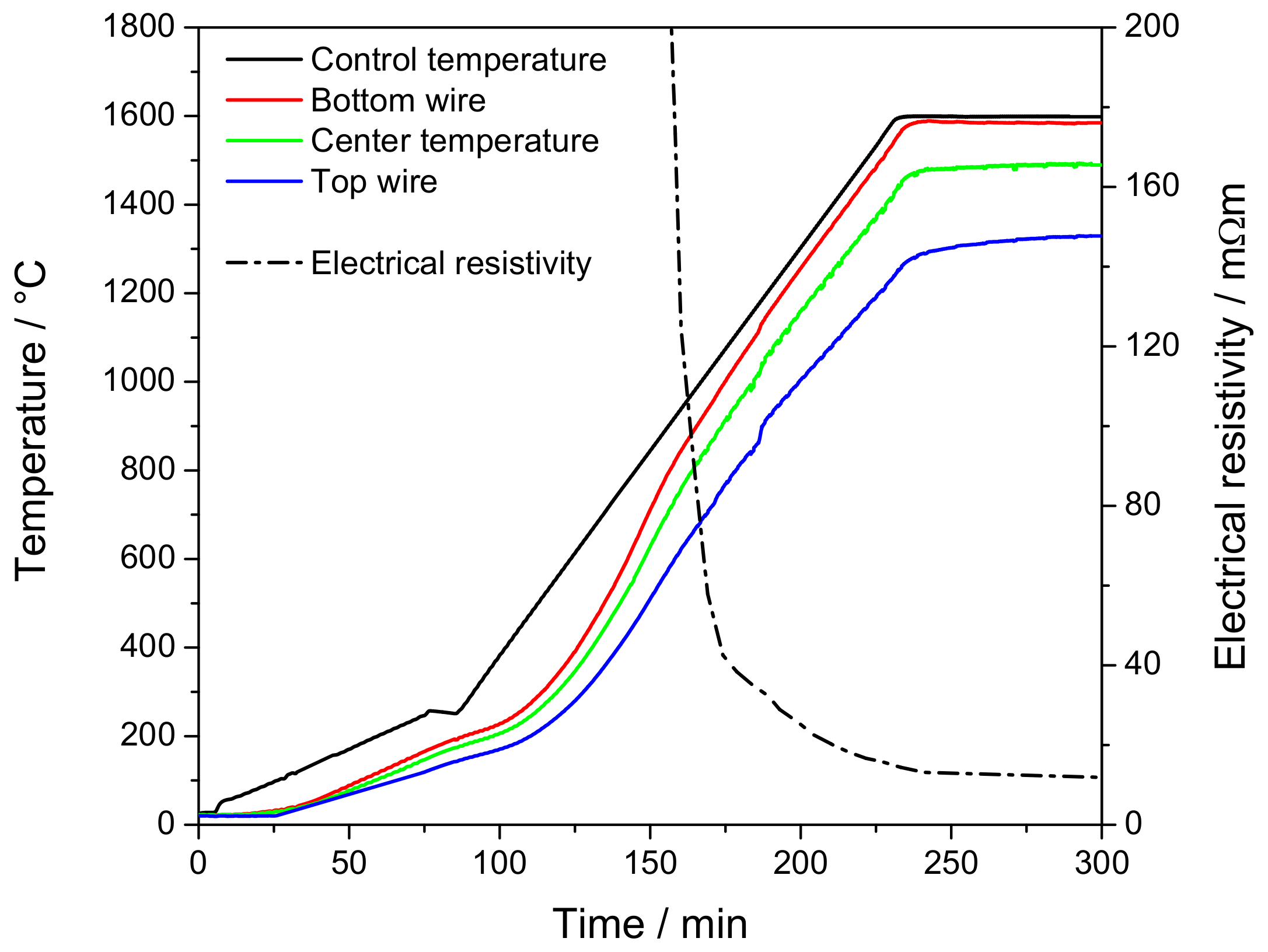
3.4. Electrical Resistivity at Elevated Temperature

Figure 3 shows the electrical resistivity of charcoal, coal, semi-coke, and metallurgical coke in the temperature range from 950 to 1650 C. Only semi-coke and metallurgical coke exhibited a detectable electrical conductivity below 950 C, as shown in the supplemental material (see Figure A1). For both coke samples, electrical resistivity slightly increased from room temperature to 300 C and subsequently decreased with increasing heat treatment temperature. Electrical resistivity of charcoal decreases from approximately 10 7 Ω · m at 600 C to 100 Ω ·m at 800 C [3], respectively from 9 · 10 3 Ω ·m to 200 Ω ·m for coal in the same temperature range [5]. At elevated temperature, electrical resistivity of large particles further decreased from 70 m Ω ·m at 1000 C to approximately 12 m Ω ·m at 1650 C for semi-coke, from approximately 11.5 to 5.5 m Ω ·m for metallurgical coke, and from 20 to 6 m Ω ·m for coal. Similar values were reported for coal and coke in the literature [22,27,34,43]. Electrical resistivity of charcoal particles decreased from higher than 100 m Ω ·m at 1000 C to a range of 14 to 18 m Ω ·m at 1600 C.
Electrical resistivity continued to decrease slightly after final temperature was reached, as shown in the supplemental material (see Figure A2). This drop was related to a decreasing temperature gradient in the measuring zone, especially between the bulk center and the top Mo-wire, as shown in the supplemental material (see Figure A3). No further reduction in electrical resistivity was observed after a stationary temperature was reached. The electrical resistivity at final temperature varied between 8.2 to 15 m Ω ·m for charcoal, 3.5 to 6.5 m Ω ·m for metallurgical coke, 8.5 to 12 m Ω ·m for semi-coke, and 4.5 to 6.5 m Ω ·m for coal. The decrease in electrical resistivity was attributed to the removal of oxygen-containing functional groups and the restructuring of the carbon matrix [44,45,46,47,48]. Differences in electrical resistivity by feedstock were related to the bulk density and final temperature of the samples, summarized in Figure 4.
After the samples were cooled overnight, electrical resistivity was evaluated at room temperature in same set-up. The last measurement at elevated temperature versus electrical resistivity measurement at room temperature is shown in Figure 5. The electrical resistivity at room temperature was scattered around measurements at elevated temperature for small and large particles, which resulted in an overestimation or underestimation at room temperature by an average of 25%. Differences were related to cooling and removing the crucible from furnace, which resulted in a thermal shrinkage of 0.5 to 1% and micromovement of bulk material. Coefficient of determination for small and large particles was calculated as 56%. However, a large difference was observed for charcoal fines, in which electrical conductivity was approximately twofold lower at room temperature compared to hot state.

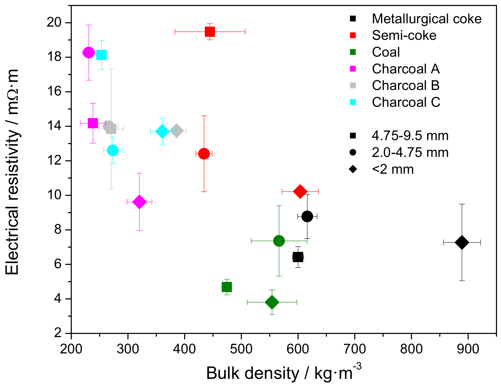
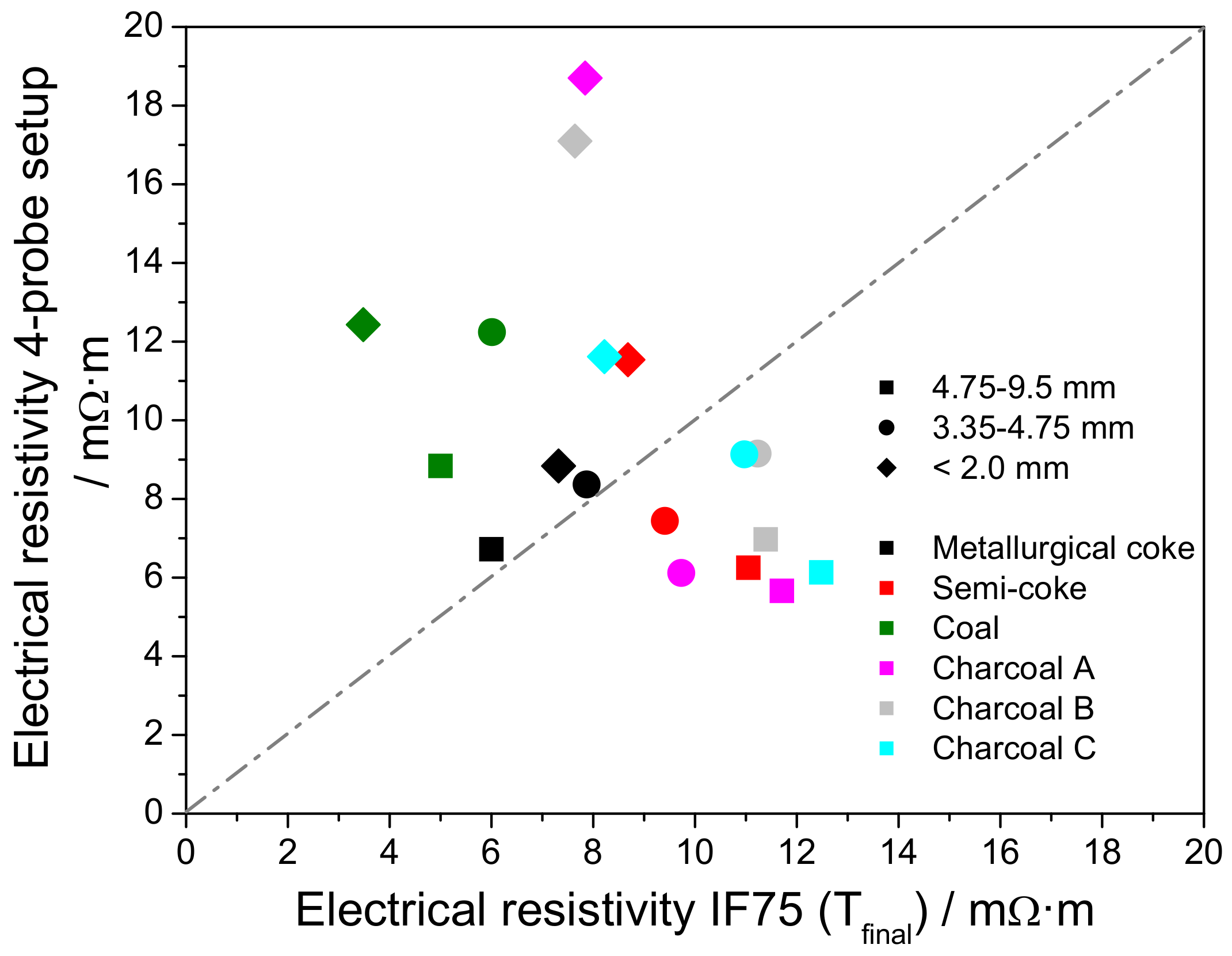
3.5. Electrical Resistivity under Load

The electrical resistivity under load of heat treated material is shown in Figure 6 for the releasing compaction force. Increasing compression force on bulk material resulted in a compaction and increased bulk density of the material, as shown in the supplemental material (see Figure A4 and Figure A5. The main compaction occurred at a force less than 100 N (50 kPa), in which the increasing force resulted in the compaction of bed material and decrease in electrical resistivity, from approximately 15 to 4 m Ω ·m for metallurgical coke, 35 to 2.4 m Ω ·m for semi-coke, 37 to 2.9 m Ω ·m for coal, and 33 to 3 m Ω ·m for charcoal. Bulk density increased by approximately 2–6% by filling the void fraction between the particles. The resistivity under load was less affected by particle size than by its initial compaction. Electrical resistivity under load of large and small particles was in an acceptable similarity to the measurements at high temperature, as shown in the supplemental material (see Figure A6).
Minor amounts of fines were formed by compaction to 250 kPa, confirming the results from the compression strength. Based on the compression strength of single particles, a pressure greater than 400 kPa can be introduced before breaking charcoal particles, and greater than 1000 kPa for metallurgical coke particles. Thus, only limited amounts of generated particles fill the void fraction of bulk material. Otherwise, increasing compaction force improves the contact between neighboring particles by increasing the number of contact points [22,32] and decreasing the air gap between particles [28]. Contact resistance can be two to ten times larger than electrical resistance from solid material [22,32,34], in which a decreasing particle size results in an increasing electrical resistivity. However, this effect is balanced by an increased number of contacts and conductive paths through the bulk.

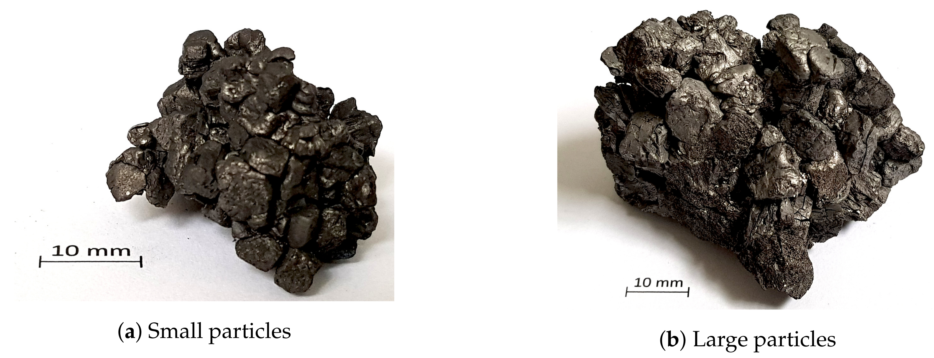
4. Surface Morphology

The surface of heat-treated material was investigated by scanning electron microscopy. Charcoal samples heat treated at 1600 C showed similar structure to its feedstock. Charcoal A exhibited mostly longitudinal tracheids cells and resin canals, schematically shown in Figure 7a, whereas a large number of vessels was observed for charcoals B and C, as shown in Figure 7b,c. The results reveal that charcoal A is a softwood, whereas charcoals B and C are hardwoods [49].
Heat-treated coal exhibited a molten surface as shown in Figure 7d. The molten surface confirmed secondary tar reactions of the metaplast [50], leading to caking of the coal particles, as shown in the supplemental material (see Figure A7). Cracks were observed in the outer surface area with a low amount of pores. Semi-coke particles on the other hand exhibited a porous outer surface, schematically shown in Figure 7e. Metallurgical coke contained molten areas with a pore structure as shown in Figure 7f.

5. Discussion

The electrical resistivity of carbonaceous reducing agents decreased with increasing heat treatment temperature [8,22,27,28,32,35], increasing bulk density and increasing load. At temperatures less 950 C, high oxygen content and disordered carbon structure act as an insulator in biomass, charcoal, and coal [3,44,45,47]. Hydrogen and oxygen content decrease with increasing heat treatment temperature by thermal decomposition and release of volatile matter, such as oxygenates CO, CO 2 , CH 4 , and H 2 [51], which result in a decrease in electrical resistivity by 5 orders of magnitude [1,3]. Semi-coke and metallurgical coke on the other hand have been produced at ~900 C and between 1100 to 1400 C in their production processes [52], and thus already provide a reduced electrical resistivity in low temperature range.
Simulation have shown that 5 to 15% of electrical current is conducted through the burden of SAF by using metallurgical coke [22]. The electrical properties of charcoal and coal at low heat treatment temperature inhibit a conduction of current in the higher regions of the SAF [1,43]. With traveling carbonaceous material to the high temperature zone of SAF, the electrical properties of charcoal approach the properties of fossil reductants such as coal and semi-coke, but remain higher than for metallurgical coke. A higher electrical resistivity enables lower tip position in submerged arc furnaces, and thus improves the heat generation in the lower part of the furnace [19].
The electrical resistivity of metallurgical coke decreased from 13 m Ω ·m at 1000 C to approximately 6.5 m Ω ·m at 1600 C for a particle size of 4.75–9.5 mm, similar to that described in the literature for larger particles (10–20 mm) [35]. It was reported that electrical resistivity decreased by approximately 50% by increasing particle size from 5–10 mm to 15–20 mm [19]. Charcoal particles larger than 2 mm were measured to approximately 50 m Ω ·m at 1100 C and 17 m Ω ·m at 1600 C, similar to larger grain sizes (5–35 mm) reported in the literature [35]. The current results indicate that the particle size affects electrical conductivity less than bulk density. The minor effect of the particle size can be explained by the increased number of contact points in carbon bed, in which particle size decreases similar to the increased number of contact points [31]. However, in industrial furnaces the contact between particles of the carbon bed can be affected by the presence of slag, which can result in an increased particle-to-particle resistance [19]. However, softwood, with the lowest density, provided an electrical conductivity similar to both hardwood samples and electrical resistivity of charcoal approached that of fossil fuels despite its twice lower bulk density.
Compacting pressure in SAF will increase by weight of the burden towards the carbon bed. Contact pressure and number of electrical contact points will increase with increasing pressure, resulting in a decreasing electrical resistivity [53,54]. Li et al. investigated electrical resistivity for high compacting pressure and concluded that electrical resistivity decreased up to a pressure of 19 GPa [55]. At compressive pressure of ~8 MPa an electrical resistivity of 2 Ω ·m can be achieved [1]. However, with increasing pressure the particles can break at the contact point and create a new or better contact between the particles, resulting in a more even current density between particles at the cost of gas permeability [32].
A major issue for replacing metallurgical coke by renewable bed material is the mechanical property. In general, charcoal provides a lower mechanical stability and higher CO 2 reactivity than coke and coal. The current investigation has shown that the durability of charcoal particles improved after heat treatment at 1600 C, indicating improved mechanical properties at the hearth of the furnace. The compression strength of heat-treated charcoal varied between 20 to 80 N, corresponding to a maximum pressure of 400 to 1600 kPa before breaking and the generation of large amounts of fines. A maximum pressure of 150 kPa is assumed by the burden in SAF based on the assumptions stated in Appendix E in the supplemental material. The thermal shrinkage indicates that between 15 to 20% of fines can be generated by bed movement and thermal stress in the burden, increasing an increased risk of clogging and slag boiling [19]. Thus, durability of carbonaceous material is considered more important for improvement than its mechanical stability towards compression.
Metallurgical coke and charcoal are assumed to last for a long time period as bed material. Xiao et al. reported that electrical resistivity of charcoal decreased with increasing residence time [56]. The current investigation showed that decreasing electrical resistivity was primarily correlated to heat treatment temperature, bulk density, and temperature profile inside the bulk, whereas prolonging the residence time did not affect electrical resistivity. At 1600 C, the charcoal structure comprises amorphous and nanocrystalline graphite, in which prolonging residence time to 12 h led to the formation of ring graphitic structures [21]. However, the increase in crystallite growth is compensated by a decrease in excess electrons [1], which resulted in a quasi-constant electrical resistivity. Thus, increasing the residence time at 1600 C has less of an effect on electrical resistivity than increasing the residence time below 950 C [1].
Measurement at room temperature resulted in an overestimation or underestimation of electrical resistivity up to 50%. Bed shrinkage and bed movement led to the collapse and formation of current paths, affecting the measurement for heat treated materials. Measurements under load demonstrated a large impact of the initial compaction on electrical resistivity at low pressure. Thus, in situ measurement at elevated temperature in the same set-up is superior to multiple measurements of pre-heat-treated material. Deviation between hot temperature and room temperature measurement was especially large for charcoal with grain sizes less than 2 mm. Results at room temperature for particles larger than 2 mm scattered around electrical resistivity at high temperature with a deviation of ~25%. The results indicate that electrical resistivity can be determined from pre-heat-treated material with acceptable accuracy for grain sizes larger than 2 mm. However, cold measurements of charcoal fines underestimated electrical resistivity by more than 50%.

6. Conclusions

Electrical properties of charcoal, coal, semi-coke, and metallurgical coke have been investigated at elevated temperature and compared to measurements at room temperature under load. The results showed that the electrical resistivity of charcoal approached that of coal and metallurgical coke at temperatures above 1400 C and was similar to semi-coke at temperatures higher than 1050 C. Heat treatment prior to electrical resistivity measurement can be carried out to determine electrical properties at room temperature at acceptable accuracy for particles larger than 2 mm, whereas electrical resistivity of powder and smaller particles is overestimated. The mechanical load of the burden mostly affected electrical conductivity at compaction pressure less 50 kPa, whereas electrical resistivity only slightly decreased at higher load. The results showed that electrical resistivity is mainly dependent on heat treatment temperature, compacting pressure, and bulk density, whereas particle size and residence time provide only minor effects. Mechanical durability of charcoal after heat treatment at 1600 C increased by 4% points to 96% and mechanical strength improved up to 80 N (corresponding 400 kPa), which is sufficient to withstand compression from the burden. In summary, charcoal can be used as an alternative carbon source for carbon bed in submerged arc furnaces with improved electrical properties.

Author Contributions

Conceptualization, G.R.S. and M.T.; methodology, G.R.S.; software, T.A.P.; validation, G.R.S., T.A.P., and A.C.; formal analysis, G.R.S., T.A.P., and A.C.; investigation, G.R.S.; resources, M.T.; data curation, T.A.P.; writing—original draft preparation, G.R.S.; writing—review and editing, M.T. and J.P.B.; visualization, G.R.S.; supervision, M.T. and J.P.B.; project administration, M.T. All authors have read and agreed to the published version of the manuscript.

Funding

This research was funded by Research Council of Norway grant number 280968. The APC was funded by Norwegian University of Science and Technology.

Acknowledgments

The authors gratefully acknowledge the financial support from Research Council of Norway (Project Code: 280968) and our industrial partners Elkem ASA, TiZir Titanium & Iron AS, Eramet Norway AS, Finnfjord AS and Wacker Chemicals Norway AS for financing the KPN Reduced CO 2 emissions in metal production project. The support from the Norwegian Research Council through the project “Metal production—education, competence and research” (Project Code: 261692/H30) is also acknowledged for encouragement and funding cooperation between South Africa and Norway.

Conflicts of Interest

The authors declare no conflicts of interest. The funders had no role in the design of the study; in the collection, analyses, or interpretation of data; in the writing of the manuscript; or in the decision to publish the results.

Abbreviations

The following abbreviations are used in this manuscript.
ACross-sectional area
aras received
dbdry basis
EAFElectric arc furnace
ICurrent
IFInduction furnace
llength
NTNUNorwegian University of Science and Technology
SAFSubmerged arc furnace
TSThermal shrinkage
T bw Temperature at the bottom Mo-wire
T C Temperature in the center of the bulk
T iw Temperature at the inner wall of the Al-tube
T ow Temperature at the outer wall of the Al-tube
T tw Temperature at the top Mo-wire
VVoltage

Appendix A. Composition of Heat Treated Material

Table A1 summarizes the product yield, proximate, and ultimate analyses of the heat-treated material. Ash content of the products remained only slightly changed with heat treatment at 1600 C, whereas volatile matter content was reduced from 13.1, 13.8, and 15.9 wt.% to less than 0.3 wt.% for charcoal, from 38.8 wt.% to less than 0.3 wt.% for coal, and from 5.4 and 0.9 wt.% to approximately 0.1 wt.% for semi-coke and metallurgical coke, respectively. Ultimate analysis was carried out at ASG Analytik-Service Gesellschaft mbH. After heat treatment, hydrogen and nitrogen contents were determined for all samples below detection limit to less than 0.1 wt.% and less than 0.5 wt.%, confirming previous results [36]. Sulfur content decreased from 0.57 to 0.5 wt.% for metallurgical coke, and from 0.35 to 0.3 wt.% for semi-coke and coal. The low volatile matter, hydrogen and oxygen contents confirm that solid residue at 1600 C is mainly composed of carbon and ash.
Table A1. Product yield, proximate, and ultimate analyses of samples after heat treatment.
Particle SizeSolid YieldAshFixed CarbonVolatile MatterCHNOS
/mm/wt.%, db/wt.%, db
Metallurgical coke
<2.0 mm94.0 ± 0.311.488.50.1 ± 0.0288.5<0.1<0.5<0.10.5
2.0 ≤ d ≤ 4.7594.0 ± 0.311.488.50.1 ± 0.0288.4<0.1<0.5<0.10.5
4.75 ≤ d ≤ 9.593.8 ± 0.311.988.00.1 ± 0.0288.1<0.1<0.5<0.10.5
Semi-coke
<2.0 mm91.4 ± 0.32.397.60.1 ± 0.0297.9<0.1<0.5<0.10.3
2.0 ≤ d ≤ 4.7590.1 ± 0.32.497.50.1 ± 0.0297.3<0.1<0.5<0.10.3
4.75 ≤ d ≤ 9.589.9 ± 0.32.397.60.1 ± 0.0397.1<0.1<0.5<0.10.3
Coal
<2.0 mm61.9 ± 0.31.7 ± 0.398.00.3 ± 0.0499.2<0.1<0.5<0.10.4
2.0 ≤ d ≤ 4.7562.8 ± 0.31.8 ± 0.297.90.3 ± 0.0398.3<0.1<0.5<0.10.3
4.75 ≤ d ≤ 9.562.9 ± 0.31.7 ± 0.398.00.3 ± 0.0698.0<0.1<0.5<0.10.3
Charcoal A
<2.0 mm82.5 ± 0.32.0 ± 0.397.70.3 ± 0.0397.9<0.1<0.5<0.1-
2.0 ≤ d ≤ 4.7580.4 ± 0.32.5 ± 0.297.20.3 ± 0.0497.5<0.1<0.5<0.1-
4.75 ≤ d ≤ 9.581.0 ± 0.33.0 ± 0.396.70.3 ± 0.0297.1<0.1<0.5<0.1-
Charcoal B
<2.0 mm79.7 ± 0.31.4 ± 0.298.40.2 ± 0.0598.5<0.1<0.5<0.1-
2.0 ≤ d ≤ 4.7581.5 ± 0.31.5 ± 0.198.30.2 ± 0.0498.4<0.1<0.5<0.1-
4.75 ≤ d ≤ 9.578.9 ± 0.31.8 ± 0.397.90.3 ± 0.0598.1<0.1<0.5<0.1-
Charcoal C
<2.0 mm83.3 ± 1.31.9 ± 0.197.90.2 ± 0.0398.0<0.1<0.5<0.1-
2.0 ≤ d ≤ 4.7584.0 ± 0.91.7 ± 0.298.10.2 ± 0.0598.1<0.1<0.5<0.1-
4.75 ≤ d ≤ 9.581.4 ± 1.52.1 ± 0.397.70.2 ± 0.0597.9<0.1<0.5<0.1-

Appendix B. Electrical Resistivity at Low Heat Treatment Temperature

Electrical conductivity of semi-coke and metallurgical coke in the temperature range from 20 to 1650 C is shown in Figure A1. Electrical resistivity slightly increased from room temperature to 300 C by thermal expansion and bed alignment. The electrical resistivity of semi-coke decreased after surpassing 600 to 900 C, which is the pyrolysis temperature in the production. Similarly, electrical resistivity of metallurgical coke decreased at temperatures higher 1100 C, which can be accounted as the heat-treatment temperature in production [52]. Thus, electrical properties can also be used to identify the prior heat treatment temperature.
Figure A1. Electrical resistivity of semi-coke and metallurgical coke from 20 to 1650 C.
Processes 08 00933 g0a1

Appendix C. Residence Time

Samples were kept at 1600 C for 60 min to ensure an even temperature profile in the alumina tube. Electrical resistivity for charcoal and fossil-reducing agent samples is shown in Figure A2. It can be noted that electrical resistivity decreased in the first 30 min after reaching the set point temperature and continued to decrease slightly afterwards. The difference in electrical resistivity was pronounced in the fine fractions (d < 2 mm), whereas fraction of large particles was less affected by increasing residence time.
Figure A2. Electrical resistivity vs. temperature after reaching set point temperature for (a) charcoal and (b) fossil-reducing agents.
Processes 08 00933 g0a2
The decrease in electrical resistivity was related to the temperature gradient in the bulk. While temperature gradient between center temperature and lower wire was stable approximately 10 min after reaching the set point temperature, top wire temperature continued to increase slightly, schematically shown in Figure A3. It can be noted that temperature gradient between bottom and top wire decreased from about 300 C at the beginning of residence time to 250 C after 60 min and kept nearly constant afterwards.
Figure A3. Temperature over time for control temperature, bottom wire, center, and top wire temperature for the heating program in IF75. Electrical resistivity over time is given for charcoal B as reference.
Processes 08 00933 g0a3

Appendix D. Electrical Resistivity under Load

Figure A4 shows the electrical resistivity and bulk density versus compression pressure for the cycle of compression and pressure release at room temperature in the 4-probe setup. Bulk density increased with increasing compaction pressure and decreases with a lower slope for pressure release, in which bulk density increased by 1.5 to 5.5% at 250 kPa compacting force, as shown in Figure A5. Compaction after releasing the pressure was measured to a range between 0.7 and 3.5%. The compaction after the cycle indicates that void space was filled by particle ordering in the bulk.
Electrical resistivity at 6 kPa compacting pressure is summarized for both set-ups in Table A2. Results are compared at final temperature in IF75 and pressure release in 4-probe setup in Figure A6. In the latter, electrical resistivity was higher for the compression route than the pressure release route due to ordering of the bulk. Charcoal and semi-coke particles larger than 2 mm showed a lower electrical resistivity in the 4-probe set-up compared to that at elevated temperature using IF75. On the other hand, electrical resistivity was higher for coal and metallurgical coke particles using the 4-probe setup at atmospheric temperature. The lower electrical resistivity was attributed to the higher bulk density and compaction for carbon material. The lower electrical resistivity of coal particles in IF75 was attributed to caking and agglomeration of particles, exemplary shown in Figure A7, whereas loose particles were used in 4-probe setup. It is known from the literature that contact resistance is higher than material resistance for dry coke beds [32]. The electrical resistivity of fines fraction remained higher at room temperature compared to experiments at elevated temperature for all investigated samples.
The results at room temperature indicate that electrical resistivity increases with increasing particle size as reported in the literature [19,32,33,34]. However, measurements at elevated temperature have shown that bulk density has just as great an influence on electrical resistivity as particle size for dry carbon beds. Thus, electrical resistivity measurements at room temperature can approve the tendency of materials, but quantification should be investigated at elevated temperature for bed material used in submerged arc furnaces.
Figure A4. Electrical resistivity and bulk density versus compaction pressure for the cycle of compacting and pressure release of (a) charcoal A, (b) charcoal B, (c) charcoal C, (d) coal, (e) semi-coke, and (f) metallurgical coke.
Processes 08 00933 g0a4
Figure A5. Compaction of carbon bulk material versus pressure for the fractions of small and large particles.
Processes 08 00933 g0a5
Table A2. Electrical resistivity of both setups at 6 kPa compaction pressure.
IF754-Probe Setup
Electrical ResistivityBulk DensityElectrical ResistivityBulk Density
/m Ω ·m/kg·m 3 /m Ω ·m/kg·m 3
Hot *After Cooling CompactionPressure Release
Metallurgical coke
Fine7.326.5092011.978.84550
Small fraction7.876.4761613.888.37560
Large fraction6.036.3860010.246.72560
Semi-coke
Fine8.6810.7762020.2811.54660
Small fraction9.419.0242019.427.44430
Large fraction11.059.4839020.946.25430
Coal
Fine3.485.9859036.0312.43750
Small fraction6.019.0152019.0212.24580
Large fraction5.008.3748022.338.84560
Charcoal A
Fine7.8412.9424041.7218.70350
Small fraction9.7311.6623024.276.12270
Large fraction11.7112.2423016.615.66270
Charcoal B
Fine7.6419.0038543.0817.10400
Small fraction11.2312.1326534.149.15290
Large fraction11.3913.0825540.996.97290
Charcoal C
Fine8.2216.7536045.7611.62410
Small fraction10.9711.8028030.999.13290
Large fraction12.4810.4926024.836.13290
* Final measurement before furnace was switched off for cooling.
Figure A6. Electrical resistivity at 6 kPa in room temperature in 4-probe set, up versus measurements in IF75 at elevated temperature.
Processes 08 00933 g0a6
Figure A7. Images of coal char agglomerate from pyrolysis at 1600 °C using (a) small particles and (b) large particles.
Processes 08 00933 g0a7

Appendix E. Estimation of the Burden Load on the Carbon Bed

Measurements in the 4-probe set-up have shown that a load on the bed material has a large impact on electrical resistivity. In industrial furnaces, the load on carbon bed is dependent on the size and operation of the electric arc furnace and induced by the raw materials of the burden. Feedstock for manganese production is comprised of manganese ore, flux melting agents, and metallurgical coke, respectively, silica and reducing agents for silicon production. Maximum pressure is obtained for manganese ore and coke blend due to the higher density of the material. Bulk density of manganese ore is in the range of 2950 to 4600 kg·m 3 with a theoretical maximum of 5230 kg·m 3 [57] and the density of metallurgical coke is approximately 780 kg·m 3 [58] with an ash content of 10%. Approximately 15 wt.% of carbon is required to reduce MnO 2 to its metal form, corresponding to a volume fraction of 45 to 55%. Thus, average density of the feedstock without considering void fraction is in the range of 1950 to 2475 kg·m 3 . A maximum compression pressure of 150 kPa was calculated according to the following equation,
Maximum compression = ρ reducing agent · w reducing agent + ρ manganese ore · w manganese ore · g · h
where ρ is the density, w is the mass fraction, g is the gravitational acceleration, and h is the burden height, which was assumed as 6 m. However, due to the void fraction between particles, additional flux agents, and larger amounts of reducing agents added, load is reduced to a range between 80 to 100 kPa. In addition, with increasing volume fraction required by charcoal, compaction pressure is further reduced to less than 55 kPa. In all cases, mechanical stability of charcoal and fossil reducing agents is sufficient to withstand the compaction pressure of the burden.

References

  1. Mochidzuki, K.; Soutric, F.; Takokoro, K.; Antal, M.J.; Toth, M.; Zelei, B.; Varhegyi, G. Electrical and Physical Properties of Carbonized Charcoals. Ind. Eng. Chem. Res. 2003, 42, 5140–5151. [Google Scholar] [CrossRef]
  2. Hoffmann, V.; Rodriguez Correa, C.; Sautter, D.; Maringolo, E.; Kruse, A. Study of the electrical conductivity of biobased carbonaceous powder materials under moderate pressure. GCB Bioenergy 2019, 11, 230–248. [Google Scholar] [CrossRef] [Green Version]
  3. Antal, M.; Grønli, M. The art, science, and technology of charcoal production. Ind. Eng. Chem. 2003, 42, 1619–1640. [Google Scholar] [CrossRef]
  4. Lehmann, J.; Rillig, M.; Thies, J.; Masiello, C.A.; Hockaday, W.C.; Crowley, D. Biochar effects on soil biota—A review. Soil Biol. Biochem. 2011, 43, 1812–1836. [Google Scholar] [CrossRef]
  5. Vorob’ev, V.; Golunov, A.; Ignat’ev, A. Carbon Reductants for the Production of Manganese Ferroalloys. Russ. Metall. 2009, 8, 752–755. [Google Scholar] [CrossRef]
  6. Griessachenr, T.; Antrekowitsch, J.; Steinlechner, S. Charcoal from agricultural residues as alternative reducing agent in metal recycling. Biomass Bioenergy 2012, 39, 139–146. [Google Scholar] [CrossRef]
  7. Adrados, A.; De Marco, I.; López-Urionabarrenchea, A.; Solar, J.; Caballero, B.; Gastelu, N. Biomass Pyrolysis Solids as Reducing Agents: Comparison with Commercial Reducing Agents. Materials 2016, 9, 3. [Google Scholar] [CrossRef]
  8. Monsen, B.; Tangstad, M.; Midtgaard, H. Use of charcoal in silicomanganese production. In Proceedings of the International Ferro-Alloys Congress X, Cape Town, South Africa, 1–4 February 2004; pp. 392–404. [Google Scholar]
  9. Surup, G.; Nielsen, H.; Großarth, M.; Deike, R.; Van den Bulcke, J.; Kibleur, P.; Müller, M.; Ziegner, M.; Yazhenskikh, E.; Beloshapkin, S.; et al. Effect of operating conditions and feedstock composition on the properties of manganese oxide or quartz charcoal pellets for the use in ferroalloy industries. Energy 2020, 193, 116736. [Google Scholar] [CrossRef]
  10. Surup, G.; Hunt, A.; Attard, T.; Budarin, V.L.; Forsberg, F.; Arshadi, M.; Abdelsayed, V.; Shekhawat, D.; Trubetskaya, A. The effect of wood composition and supercritical CO2 extraction on charcoal production in ferroalloy industries. Energy 2020, 193, 116696. [Google Scholar] [CrossRef]
  11. World Steel Association. Steel’s Contribution to a Low Carbon Future and Climate Resilient Societies—World Steel Position Paper; World Steel Association: Brussels, Belgium, 2017. [Google Scholar]
  12. Olsen, S.; Monsen, B.; Lindstad, T. Emissions from the Production of Manganese and Chromium Alloys in Norway. In Proceedings of the 56th Electric Furnace Conference, New Orleans, LA, USA, 15–18 November 1998; pp. 1–7. [Google Scholar]
  13. Lindstad, T.; Olsen, S.; Tranell, G.; Færden, T.; Lubetsky, J. Greenhouse gas emissions from ferroalloy production. In Proceedings of the International Ferro-Alloys Congress XI, New Delhi, India, 18–21 February 2007; pp. 457–466. [Google Scholar]
  14. Kero, I.; Eidem, P.; Ma, Y.; Indresand, H.; Aarhaug, T.; Grådahl, S. Airborne Emissions from Mn Ferroalloy Production. JOM 2019, 71, 349–365. [Google Scholar] [CrossRef] [Green Version]
  15. Westfall, L.; Davourie, J.; Ali, M.; McGough, D. Cradle-to-gate life cycle assessment of global manganese alloy production. Int. J. Life Cycle Assess. 2016, 21, 1573–1579. [Google Scholar] [CrossRef] [Green Version]
  16. Mathieson, J.; Rogers, H.; Somerville, M.; Jahanshahi, S.; Ridgeway, P. Potential for the use of biomass in the iron and steel industry. In Proceedings of the Chemeca 2011, Engineering a Better World, Sydney, Australia, 18–21 September 2011; pp. 1–12. [Google Scholar]
  17. Surup, G.; Nielsen, H.; Heidelmann, M.; Trubetskaya, A. Characterization and reactivity of charcoal from high temperature pyrolysis (800–1600 C). Fuel 2019, 235, 1544–1554. [Google Scholar] [CrossRef]
  18. Lindstad, T.; Monsen, B.; Osen, K. How the ferroalloys industry can meet greenhouse gas regulations. In Proceedings of the International Ferro-Alloys Congress XII, Helsinki, Finland, 6–9 June 2010; pp. 63–70. [Google Scholar]
  19. Eidem, P.; Tangstad, M.; Bakken, J.; Ishak, R. Influence of coke particle size on the electrical resistivity of coke beds. In Proceedings of the International Ferro-Alloys Congress XII, Helsinki, Finland, 6–9 June 2010; pp. 349–358. [Google Scholar]
  20. Hussein, A.; Larachi, F.; Ziegler, D.; Alamdari, H. Effects of heat treatment and acid washing on properties and reactivity of charcoal. Biomass Bioenergy 2016, 90, 101–113. [Google Scholar] [CrossRef]
  21. Surup, G.; Foppe, M.; Schubert, D.; Deike, R.; Heidelmann, M.; Timko, M.T.; Trubetskaya, A. The effect of feedstock origin and temperature on the structure and reactivity of char from pyrolysis at 1300–2800 C. Fuel 2019, 235, 306–316. [Google Scholar] [CrossRef]
  22. Eidem, P. Electrical Resistivity of Coke Beds. Ph.D. Thesis, NTNU, Trondheim, Norway, 2008. [Google Scholar]
  23. Surup, G. Renewable Reducing Agents for the Use in Ferroalloy Industries. Ph.D. Thesis, University of Agder, Kristiansand, Norway, 2019. [Google Scholar]
  24. Suopajärvi, H.; Pongrácz, E.; Fabritius, T. The potential of using biomass-based reducing agents in the blast furnace: A review of thermochemical conversion technologies and assessments related to sustainability. Renew. Sustain. Energy Rev. 2013, 25, 511–528. [Google Scholar] [CrossRef]
  25. Suopajärvi, H.; Kemppainen, A.; Haapakangas, J.; Fabritius, T. Extensive review of the opportunities to use biomass-based fuels in iron and steelmaking processes. J. Clean. Prod. 2017, 148, 709–734. [Google Scholar] [CrossRef]
  26. Suopajärvi, H.; Umeki, K.; Mousa, E.; Hedayati, A.; Romar, H.; Kemppainen, A.; Wang, C.; Phounglamcheik, A.; Tuomikoski, S.; Norberg, N.; et al. Use of biomass in integrated steelmaking—Status quo, future needs and comparison to other low-CO2 steel production technologies. Appl. Energy 2018, 213, 384–407. [Google Scholar] [CrossRef] [Green Version]
  27. Dijs, H.; Smith, D.J. Factors affecting the resistivity and reactivity of carbonaceous reducing agents for the electric-smelting industry. J. S. Afr. Inst. Min. Metall. 1980, 80, 286–296. [Google Scholar]
  28. Adinaveen, T.; Vijaya, J.J.; Kennedy, L. Comparative Study of Electrical Conductivity on Activated Carbons Prepared from Various Cellulose Materials. Arab. J. Sci. Eng. 2014, 41, 55–65. [Google Scholar] [CrossRef]
  29. Espinola, A.; Miguel, P.; Salles, M.; Pinto, A. Electrical properties of carbons - resistance of powder materials. Carbon 1986, 24, 337–341. [Google Scholar] [CrossRef]
  30. Sánchez-González, J.; Macías-García, A.; Alexandre-Franco, M.; Gómez-Serrano, V. Electrical conductivity of carbon blacks under compression. Carbon 2005, 43, 741–747. [Google Scholar] [CrossRef]
  31. Tsybul’kin, G. On the Calculation of the Electrical Resistivity of Conducting Loose Materials. Elektrometallurgiya 2010, 2011, 594–598. [Google Scholar] [CrossRef]
  32. Eidem, P.; Tangstad, M.; Bakken, J. Measurement of material resistivity and contact resistance of metallurgical coke. In Proceedings of the International Ferro-Alloys Congress XI, New Delhi, India, 18–21 February 2007; pp. 561–571. [Google Scholar]
  33. Buryak, V.; Vasil’chenko, G.; Chirka, T.; Konstantinov, S. Specific electrical resistance of carbon materials. Refract. Ind. Ceram. 2013, 54, 215–219. [Google Scholar] [CrossRef]
  34. Tangstad, M.; Beukes, J.; Steenkamp, J.; Ringdalen, E. 14—Coal-based reducing agents in ferroalloys and silicon production. In New Trends in Coal Conversion Combustion, Gasification, Emissions, and Coking; Woodhead Publishing: Cambridge, UK, 2019; pp. 405–438. [Google Scholar]
  35. Monsen, B.; Tangstad, M.; Solheim, I.; Syvertsen, I.; Ishak, R.; Midtgaard, H. Charcoal for manganese alloy production. In Proceedings of the International Ferro-Alloys Congress XI, New Delhi, India, 18–21 February 2007; pp. 297–310. [Google Scholar]
  36. Surup, G.; Vehus, T.; Eidem, P.; Trubetskaya, A.; Nielsen, H. Characterization of renewable reductants and charcoal-based pellets for the use in ferroalloy industries. Energy 2019, 167, 337–345. [Google Scholar] [CrossRef]
  37. Antal, M.; Mok, W.; Varhegyi, G.; Szekely, T. Review of methods for improving the yield of charcoal from biomass. Energy Fuels 1990, 4, 221–225. [Google Scholar] [CrossRef]
  38. Olsson, J.; Jaglid, U.; Pettersson, J.; Hald, P. Alkali metal emission during pyrolysis of biomass. Energy Fuels 1997, 11, 779–784. [Google Scholar] [CrossRef]
  39. Riaza, J.; Mason, P.; Jones, J.; Gibbins, J.; Chalmers, H. High temperature volatile yield and nitrogen partitioning during pyrolysis of coal and biomass fuels. Fuel 2019, 248, 215–220. [Google Scholar] [CrossRef]
  40. Efika, E.; Onwudili, J.; Williams, P. Products from the high temperature pyrolysis of RDF at slow and rapid heating rates. J. Anal. Appl. Pyrolysis 2015, 112, 14–22. [Google Scholar] [CrossRef]
  41. Wakchaure, G.; Mani, I. Thermal and Storage Characteristics of Biomass Briquettes with Organic Binders. J. Agric. Eng. Res. 2011, 48, 43–53. [Google Scholar]
  42. Wang, L.; Barta-Rajnai, E.; Hu, K.; Higashi, C.; Skreiberg, Ø.; Grønli, M.; Czégény, Z.; Jakab, E.; Myrvågnes, V.; Várhegyi, G.; et al. Biomass Charcoal Properties Changes during Storage. Energy Procedia 2017, 105, 830–835. [Google Scholar] [CrossRef]
  43. Koursaris, A.; See, J. The resistivity of mixtures of Mamatwan manganese ore and reducing agents. J. S. Afr. Inst. Min. Metall. 1980, 80, 229–238. [Google Scholar]
  44. Mrozowski, S. Semiconductivity and Diamagnetism of Polycrystalline Graphite and Condensed Ring Systems. Phys. Rev. 1952, 85, 609–620. [Google Scholar] [CrossRef]
  45. Golden, T.; Jenkins, R.; Otake, Y.; Scaroni, A. Oxygen Complexes on Carbon Surfaces. In Proceedings of the Workshop on The Electrochemistry of Carbon, Cleveland, OH, USA, 17–19 August 1983; Volume 84, pp. 61–78. [Google Scholar]
  46. Pantea, D.; Darmstadt, H.; Kaliaguine, S.; Sümmchen, L.; Roy, C. Electrical conductivity of thermal carbon blacks Influence of surface chemistry. Carbon 2001, 39, 1147–1158. [Google Scholar] [CrossRef]
  47. JoséSánchez-González, J.; Stoeckli, F.; Centeno, T. The role of the electric conductivity of carbons in the electrochemical capacitor performance. J. Electroanal. Chem. 2011, 657, 176–180. [Google Scholar] [CrossRef] [Green Version]
  48. Razd’yakonova, G. The electrical conductivity of carbon-black filled vulcanisates. Int. Polym. Sci. Tech. 2013, 40, 11–15. [Google Scholar] [CrossRef]
  49. Panshin, A.; De Zeeuw, C. Textbook of Wood Technology: Structure, Identification, Properties, and uses of the Commercial Woods of the United States and Canada; Number Bd. 1 in McGraw-Hill Series in Forest Resources; McGraw-Hill: New York, NY, USA, 1980. [Google Scholar]
  50. Trubetskaya, A.; Jensen, P.; Jensen, A.; Steibel, M.; Spliethoff, H.; Glarborg, P. Influence of fast pyrolysis conditions on yield and structural transformation of biomass chars. Fuel Process. Technol. 2015, 140, 205–214. [Google Scholar] [CrossRef] [Green Version]
  51. Weber, K.; Quicker, P. Properties of biochar. Fuel 2018, 217, 240–261. [Google Scholar] [CrossRef]
  52. Díez, M.; Alvarez, R.; Barriocanal, C. Coal for metallurgical coke production: Predictions of coke quality and future requirements for cokemaking. Int. J. Coal. Geol. 2002, 50, 389–412. [Google Scholar] [CrossRef]
  53. Babu, S.; Santella, M.L.; Feng, Z.; Riemer, B.; Cohron, J. Empirical model of effects of pressure and temperature on electrical contact resistance of metals. Sci. Technol. Weld. Join. 2001, 6, 126–132. [Google Scholar] [CrossRef]
  54. Rani, A.; Nam, S.; Oh, K.; Park, M. Electrical Conductivity of Chemically Reduced Graphene Powders under Compression. Carbon Lett. 2010, 11, 90–95. [Google Scholar] [CrossRef] [Green Version]
  55. Li, X.; Mao, H. Solid Carbon at High Pressure: Electrical Resistivity and Phase Transition. Phys. Chem. Miner. 1994, 21, 1–5. [Google Scholar]
  56. Xiao, G.; Xiao, R.; Jin, B.; Zuo, W.; Liu, J.; Grace, J. Study on Electrical Resistivity of Rice Straw Charcoal. J. Biobased Mater. Bioenergy 2010, 4, 426–429. [Google Scholar] [CrossRef]
  57. Emerson, D.; Schmidt, P. Pyrolusitic supergene manganese oxides: Inductive properties, EM conductivity and magnetic susceptibility. Preview 2018, 197, 42–50. [Google Scholar]
  58. Montiano, M.; Díaz-Faes, E.; Barriocanal, E.; Alvarez, R. Influence of biomass on metallurgical coke quality. Fuel 2014, 116, 175–182. [Google Scholar] [CrossRef] [Green Version]
Figure 1. Schematic of the electrical measurement set-up at NTNU/SINTEF.
Processes 08 00933 g001
Figure 2. Product yields of char for fines, small particles, and large particles after high temperature measurement. The char yield is separated in ash, fixed carbon, and volatile matter by its proximate analysis. The error bars characterize the standard deviations between the experiments.
Processes 08 00933 g002
Figure 3. Temperature dependence of electrical resistivity of different grain sizes: (a) large particles (4.75–9.5 mm), (b) small particles (2.00–4.75 mm), and (c) fines (<2 mm).
Processes 08 00933 g003
Figure 4. Electrical resistivity at 1600 C after 1 h residence time versus bulk density.
Processes 08 00933 g004
Figure 5. Comparison of electrical resistivity measurement at elevated temperature to measurement at room temperature after cooling.
Processes 08 00933 g005
Figure 6. Electrical resistivity and bulk density versus compaction pressure for (a) charcoal A, (b) charcoal B, (c) charcoal C, (d) coal, (e) semi-coke, and (f) metallurgical coke.
Processes 08 00933 g006
Figure 7. SEM images of (a) heat-treated charcoal A, (b) heat-treated charcoal B, (c) heat-treated charcoal C, (d) heat-treated coal, (e) heat-treated semi-coke, and (f) heat-treated metallurgical coke.
Processes 08 00933 g007
Table 1. Proximate and ultimate analyses of feedstocks.
FeedstockCharcoal ACharcoal BCharcoal CCoalSemi-CokeMetallurgical Coke
Proximate analysis (wt.%)
Moisture (ar)27.512.15.0212.28.8<0.1
Volatile matter (db)15.913.813.138.85.40.9
Fixed carbon (db)82.884.885.259.388.687.9
Ash (db)3.971.891.751.255.8710.90
Ultimate analysis (wt.%, dry basis)
C85.583.588.178.388.587.7
H1.952.282.514.721.240.21
N<0.50<0.50<0.501.611.441.75
O7.408.687.1413.772.64<0.10
S<0.01<0.01<0.010.350.310.57
Table 2. Mechanical properties of charcoal, coal, and semi-coke before and after heat treatment.
TS/%Mechanical Durability/%Compression Strength/N
SampleHeat-TreatedRawHeat-TreatedRawHeat-Treated
Charcoal A17.6 ± 1.293.695.6 ± 1.320–6040–80
Charcoal B16.6 ± 2.493.596.1 ± 0.430–6040–80
Charcoal C19.4 ± 3.191.896.0 ± 0.130–6040–80
Coal4.5 ± 0.699.494.3 ± 1.15070
Semi-coke7.6 ± 0.699.898.4 ± 0.680100
Metallurgical coke1.9 ± 0.199.899.6 ± 0.1100100

