Article

Numerical Investigation of Fluid Flow and In-Cylinder Air Flow Characteristics for Higher Viscosity Fuel Applications

by
Mohd Fadzli Hamid
1,
Mohamad Yusof Idroas
1,
Shukriwani Sa’ad
2,
Teoh Yew Heng
1,
Sharzali Che Mat
3,
Zainal Alimuddin Zainal Alauddin
1,
Khairul Akmal Shamsuddin
4,
Raa Khimi Shuib
5 and
Muhammad Khalil Abdullah
5,*
1
School of Mechanical Engineering, Universiti Sains Malaysia, Engineering Campus, Seri Ampangan, Nibong Tebal 14300, Malaysia
2
Faculty of Computer, Media and Technology Management, TATI University College, Kemaman 24000, Malaysia
3
Faculty of Mechanical Engineering, Universiti Teknologi MARA Cawangan Pulau Pinang, Permatang Pauh 13500, Malaysia
4
Mechanical Section, Universiti Kuala Lumpur, Malaysian Spanish Institute, Kulim 09000, Malaysia
5
School of Material and Mineral Resources Engineering, Universiti Sains Malaysia, Engineering Campus, Seri Ampangan, Nibong Tebal 14300, Malaysia
*
Author to whom correspondence should be addressed.
Processes 2020, 8(4), 439; https://doi.org/10.3390/pr8040439
Submission received: 6 January 2020 / Revised: 11 February 2020 / Accepted: 13 February 2020 / Published: 8 April 2020

Abstract

:
Generally, the compression ignition (CI) engine that runs with emulsified biofuel (EB) or higher viscosity fuel experiences inferior performance and a higher emission compared to petro diesel engines. The modification is necessary to standard engine level in order to realize its application. This paper proposes a guide vane design (GVD), which needs to be installed in the intake manifold, is incorporated with shallow depth re-entrance combustion chamber (SCC) pistons. This will organize and develop proper in-cylinder airflow to promote better diffusion, evaporation and combustion processes. The model of GVD and SCC piston was designed using SolidWorks 2017; while ANSYS Fluent version 15 was utilized to run a 3D analysis of the cold flow IC engine. In this research, seven designs of GVD with the number of vanes varied from two to eight vanes (V2–V8) are used. The four-vane model (V4) has shown an excellent turbulent flow as well as swirl, tumble and cross tumble ratios in the fuel-injected region compared to other designs. This is indispensable to break up heavier fuel molecules of EB to mix with the air that will eventually improve engine performance.

1. Introduction

A diesel engine is one of the most indispensable power generation systems and is mainly used in industrial, public transportation, power generation, heavy-duty machinery, and agricultural applications due to their higher fuel-conversion efficiency, power output, torque and reliability compared to gasoline engines [1]. Furthermore, the emissions such as carbon monoxide (CO), hydrocarbon (HC) and carbon dioxide (CO2) from a diesel engine is much lesser compared to the gasoline engine emissions. However, diesel engine remains to be an important source of pollution as their usage leads to release of nitrogen oxides (NOx), black smoke, particulate matter (PM) and sulfur oxides (SOx) that are detrimental to both environment and human health [2]. In fact, the emissions from diesel engines have been classified as carcinogenic by the International Agency for Research on Cancer (IARC). It is based on sufficient evidence that high exposure to diesel emissions can be a risk of lung cancer [3], soot emissions can cause cardiovascular diseases [4], while NOx emissions can cause ground level ozone [5], smog [6] and acid rain [7].
On the other hand, fluctuating petroleum prices, fossil fuel depletion, energy demand escalations and stringent emission regulations have intensified the look-out of the scientific community for alternative renewable fuels in place of the existing fossil fuel. Therefore, non-conventional types of fuel, made from biological resources such as biofuel and biodiesel, have been researched. These studied aimed to tackle the problems that arise due to the comparable properties with that of fossil fuels. However, this alternative fuel not only has high viscosity and boiling point, but also low volatility and calorific values. Biofuel, particularly refined palm oil (RPO) is readily made, safe to be handled and stored and is renewable [8]. However, direct use of this oil degrades the engine performance if operated for a prolonged period due to their high viscosity and low volatility, which causes filters, fuel lines and injectors to be clogged. In addition, engine problems such as piston ring sticking, carbon deposit build-up and lubricating oil thickening were also observed [8], therefore it would be necessary to overhaul, repair and replace some parts of the diesel engine.
The prominent factors that control and govern the combustion process depend on the air motion within the engine, charge temperature, compression ratio, spray structure, burning rate, piston bowl geometry, injection strategies, auto ignition fuels, and fuel molecular structure [9]. There is a significant influence of piston bowl geometry with respect to the combustion and the amount of emission as it strongly affects the mixing of air and fuel prior to the start of injection (SOI). Jing Li et al. [10] investigated the effect of piston bowl geometry on combustion and emissions using a high viscous fuel (biodiesel). The studies inferred that at low engine speed, the shallow depth re-entrance combustion chamber (SCC) piston exhibited better engine performance. Using computational fluid dynamics (CFD) analysis, Hamid et al. [11] discovered that the SCC piston had an ability to generate high swirl, tumble and cross tumble ratios. They also observed that the turbulence kinetic energy was increased, had a well-organized flow and a better air fuel mixture, especially for high viscous fuel applications. Consequently, the combustion efficiency had been improved and reduced incomplete combustion. In addition, the SCC piston is a preferable design since it can be run with high viscosity alternative fuel in the diesel engine.
The inherent long carbon chains become a limitation to biofuels as their nature results in high viscosity and density. The in-cylinder airflow rate was low and produced an adverse effect, as previously mentioned, because of the physiochemical nature of the alternative fuel, that produced an undesired injection profile which degraded cone angle and increased the length of penetration spraying due to high viscosity. Several measures have been taken to lower the viscosity of the alternative fuel for producing an injection profile closed to the diesel, e.g., blending alternative fuel with fossil fuel [12], preheating the alternative fuel [13], emulsification of alternative fuel [14], nano-fluid additives [15], mixing with low and high viscosity biofuel [16] and adjusting injection timing [17,18,19]. In general, these techniques partially minimized those aforementioned issues, but are still lacking certain requisites compared to the engines using petrol and diesel fuels.
Theoretically, when the in-cylinder airflow rate increased, the swirl, tumble, cross tumble ratios and kinetic energy of turbulence also increases and accelerates the in-cylinder evaporation and diffusion. These effects generally will enhance engine performance such as higher engine power and lower brake specific fuel consumption (BSFC). To enhance and improve the in-cylinder airflow rate and its characteristics, several strategies can be implemented, such as redesigning the airflow intake manifold, modifying the piston bowl and guide vanes to guide the inlet airflow [20].
Therefore, this research will investigate numerically the effect of the numbers of GVD incorporated with the SCC pistons to enhance and organize the in-cylinder airflow rate and its characteristics. Based on the previous literature, the geometry of the guide vanes consists of four main parameters: vane number, angle, height and length. Nevertheless, this research is limited to the numbers of GVD regardless of other parameters as including several parameters tend to make the analysis complex and increases the computational time consumption. Therefore, the remaining parameters were kept constant according to the previous researchers [21,22]. The design model of the SCC piston is modification suited on the YANMAR L70 engine specifications. The details of the designs is described in the following sections.

2. Methodology

2.1. Computer Simulation

There are four main steps in order to investigate the airflow rate and its characteristics, namely to draw the SCC piston and GVD, mesh the parts, define their boundary condition and analyze the cold flow IC engine. SolidWorks 2017 and ANSYS-FLUENT v15 software were utilized to prepare the model and analyze the in-cylinder airflow in the transient engine cycle without combustion. The complete details of the computer simulation setup is described in the following section.

2.2. Guide Vane Design (GVD)

GVD is designed specifically to enhance the air velocity due to swirling flow generated. The geometry of GVD consists of vanes number (N), height (Hv), length (l) and angle (θ) which are illustrated in Figure 1 and the specification of GVD is shown in Table 1. GVD dimensions play an important parameter in generating optimized in-cylinder air flow characteristics. They will guide the intake airflow into the combustion chamber, generate turbulence phenomena and sustain swirl momentum until the end of the expansion stroke. The increasing swirl flow will produce high convective heat transfer coefficient inside the combustion chamber [23]. Nevertheless, if the number of vanes increases, it tends to obstruct the airflow and affect volumetric efficiency [24]. By considering this, our research has a limit to eight guide vanes (V8) starting with a base (without vane). The vane twist angle was fixed at 35° angle.

2.3. Shallow Depth Re-Entrance Combustion Chamber (SCC)
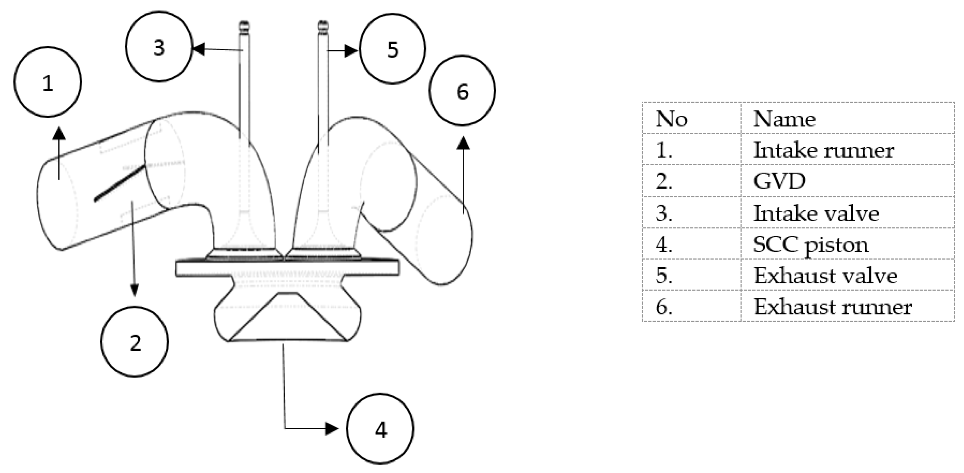
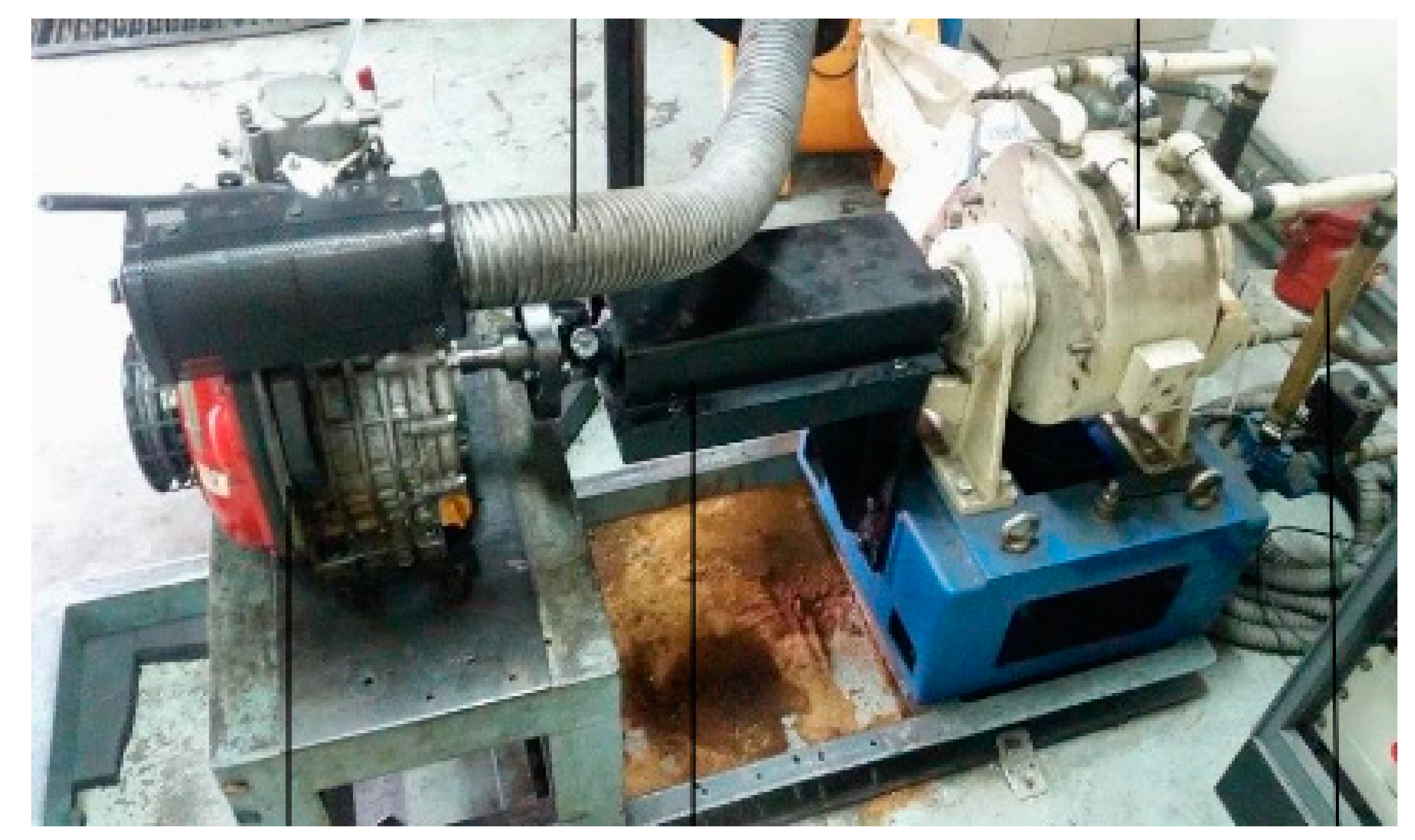
To improve the mixing of air and fuel, most of the important modifications were performed on the engine design. The nature of formation of mixture in the engine cylinder is predominantly dependent on the shape of the combustion chamber and the piston bowl design. Running the emulsified biofuel with high viscosity will deteriorate the injection profile. Hwang et al. [25] carried out studies on the injection profile using waste cooking oil biodiesel. They observed that the penetration length was longer, and the cone angle was shorter compared to petrol and diesel fuels. To mitigate these issues, many researchers [26] suggested that the piston bowl design needs to be modified for smooth running with high viscosity fuel. They discovered that the SCC piston bowl design (as shown in Figure 2) is recommended since it can organize the airflow well; swirl ratio (Rs), tumble ratio (RT), cross tumble ratio (RCT) and break the penetration length of injection to facilitate enhanced mixing with the surrounding air. Therefore, the effect of the GVD and SCC piston combination will be focused on this research.

2.4. Engine Model

The geometry of the engine model was adapted from the experimental Yanmar model type L70AE-DTM CI generator with a four-stroke direct injection, vertical cylinder, one cylinder, one intake valve and one exhaust valve. The technical specification of the engine is given in Table 2.

3. Simulation Setting

The engine geometry of Yanmar L70AE-DTM was modelled using SolidWorks 2017. The GVD, intake runner, exhaust runner, cylinder, intake valve and the exhaust valve have been modelled separately and assembled together as illustrated in Figure 3. The assembled model of the engine was exported to the CFD software, namely ANSYS-FLUENT v15. The software was used to construct a solver, comprising of mathematical computations that simulates and analyses cold flow. To compute the parameters representing fluid flow, both valves were set as solid domains as in reality while the others were set as a fluid flow domain. The moving boundaries were the main challenges in order to simulate a 3D IC engine such as piston bowl, valve and cylinder. The moving grid and remapping mesh were the common strategies used by many researchers [27,28]. The mesh generation on this research was based on assembly level meshing technique. The CFD simulation setting was based according to the cold flow IC engine published by ANSYS Inc. [29].
The equations governing the fluid flow which formed the basis for simulation are the conservation of mass, momentum and energy (energy equation) [30,31]. The conservation of mass is derived based on the control volume and the corresponding differential Equation [32]. It is written as:
p t + ( ρ U ) = 0
ρ is the fluid density and U is three-dimensional flow velocities in the x, y and z directions.
The conservation of linear momentum is derived based on the Newton’s second law where the surface forces are the control volumes and forces are the body of the control volume. It can be written as:
( ρ U ) t + ( ρ U × U ) = p τ + S M
p is the fluid pressure, τ is the strain rate and S M is a momentum source. This equation is also known as the Navier–Stoke equation [33].
The rate of energy change inside the fluid element is also known as the energy equation and it is given by:
( ρ h t o t ) t ρ t ( ρ U h t o t ) = ( λ T ) + ( U · τ ) + U · S M
h t o t and λ are the total enthalpy and thermal conductivity, respectively.
Shear Stress Transport (SST) is a two-equation eddy-viscosity model that was used in this numerical study. This model is a combination of the k-ω and k-ε turbulence models. It is a low Reynolds number model. It resolution has similar requirements to the k-ω model and the low Reynolds number k-ε turbulence model, but its formulation abolishes some weakness displayed by pure k-ω and k-ε turbulence models. While the k-ω model pertains to the inner boundary layer, the k-ε model plays a role in the outer region. The combinational model overcame the limitation of shear stress until 5% turbulence intensity in the adverse gradient region, wherein it is sufficient to consider fully developed flow turbulence. The conditions of temperature and pressure were set at 300 K and 1 atm respectively. The detailed information on the setting used for the models and their limitations can be referred to ANSYS FLUENT v15–Solver Theory Guide [26].
On the basis of the physical boundary conditions of the engine, the simulation was carried out in two distinct phases of analysis; intake analysis and intake port analysis. Intake analysis is related to the intake runner, while intake port analysis corresponds to the clearance volume prior to the downward movement of the piston and intake runner in the y-direction and drawing of air into the cylinder. The components that are not applicable in this analysis were suppressed since there was no contribution to the results and to reduce the computation time during calculations.
The results of the intake analysis were transferred to the compression and expansion analysis for further simulations. During the compression and expansion analysis, the intake and exhaust valves remained closed while air was compressed during the upward movement of the piston towards the top dead center (TDC) and expanded during the downward movement towards the bottom dead center (BDC). The only domain applicable during this analysis was the cylinder volume, where the volume changed due to the motion of the piston being progressed up and down via the moving mesh. To retain the stability of the simulation progress, the time step must be small enough to simulate the moving mesh.

4. Results and Discussion

The in-cylinder airflow rate and its characteristics are well-recognized such that they can enhance the evaporation, diffusion and combustion process. As a result, it can be utilized for emulsified biofuel to improve engine performance and reduce engine emissions. Results and discussion will focus on the events taking place within the fuel injection period or ignition delay, the time difference between start of injection (SOI) and start of combustion (SOC). Due to the default setting of Yanmar L70AE-DTM (manufacturer setting), the fuel injection is at 14° before TDC, therefore the results will be covered at a crank angle (CA) from 346° SOI until 352° SOC.

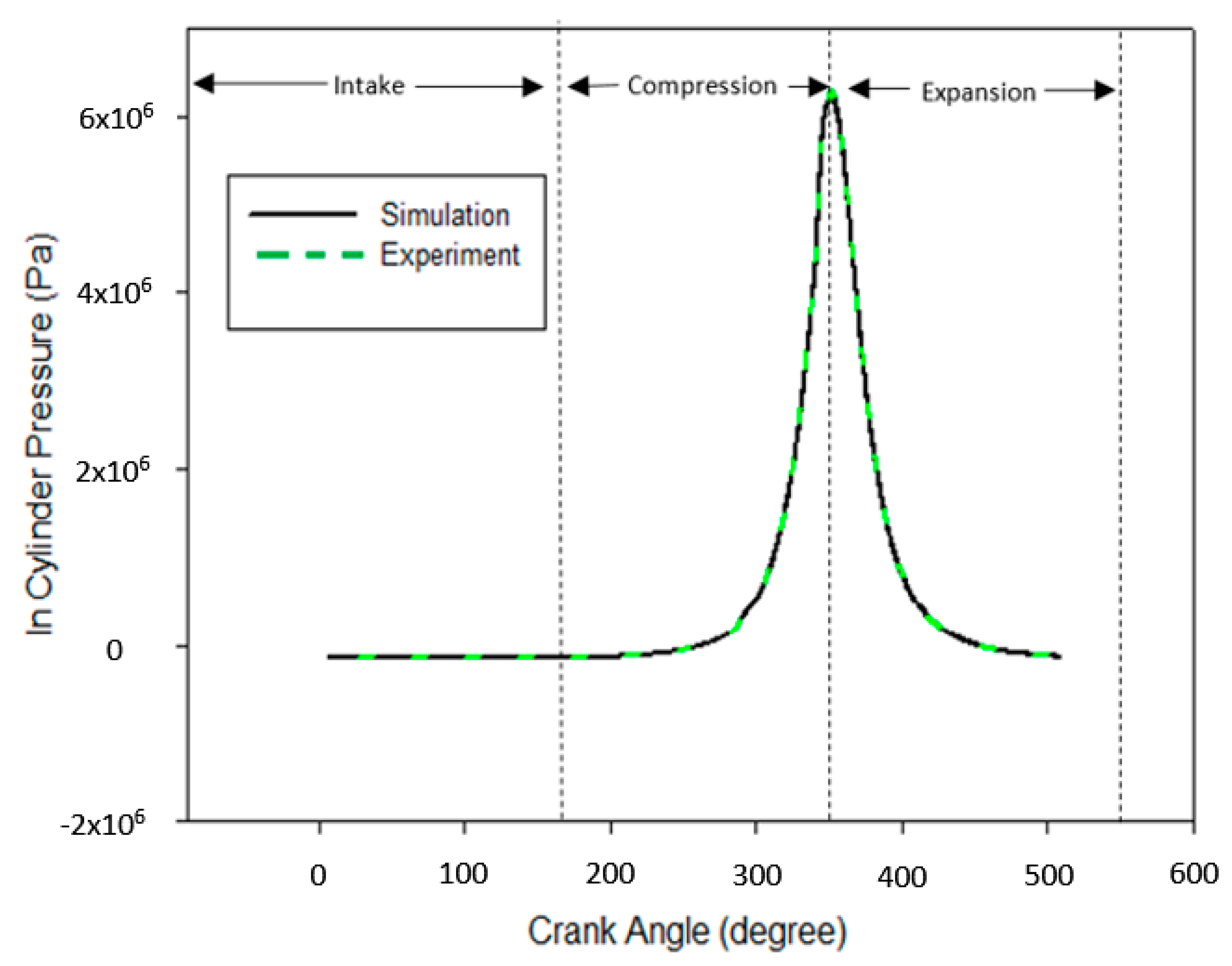
4.1. Numerical Validations

The purpose of the experimental setup is to validate the numerical simulation, which was carried out in the test rig of single a cylinder of Yanmar engine as shown in the Figure 4. During the experiment setup, a high sensitivity water-cooled precision type sensor Kistler 7061B, magnetic pickup shaft encoder and TDC position optical sensor were used to measure the in-cylinder pressure and crank angle data. A sensor of type 7061B was screwed directly into the standard M14 hole. The position of the sensor was mounted near the valve for better accuracy of the values. K-type thermocouple was used to measure the boundary temperatures, at the intake and exhaust boundaries, and the thermocouple was positioned as close as possible to the cylinder head. The SCC piston was used to validate the experimental data.
Figure 5 shows the in-cylinder pressure against the crank angle (θ) diagram from the simulation and experiment results without combustion at a rotational speed of 2000 rpm. The data measurement for the intake temperature and pressure are 302 K and 1.02 bar, respectively. The graph shows the variation of pressure between 0° to 540°. Based on the figure, a reasonable agreement between experimental and numerical results with a slight difference of about 7% peak pressure is witnessed. This minor deviation might be due to the gas seepage from the cylinder into the crankcase.

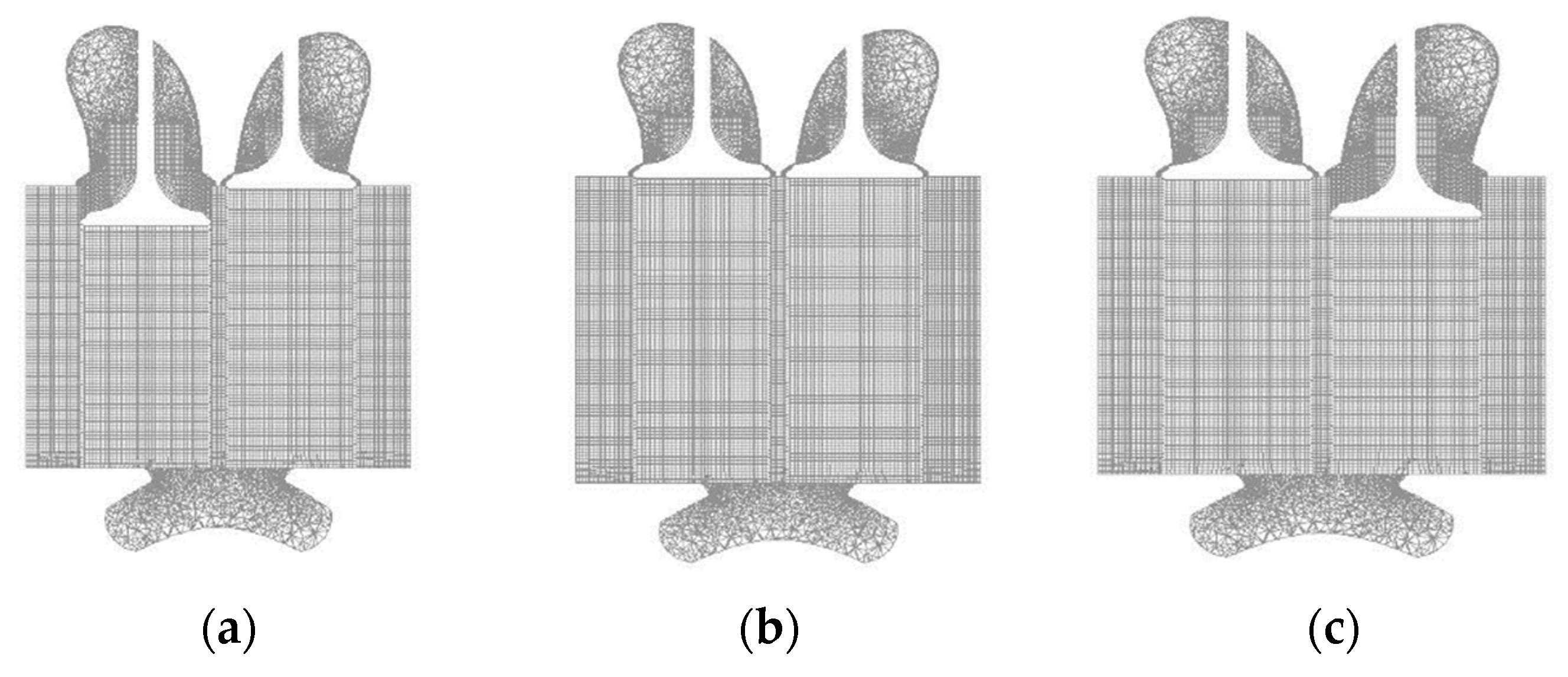
4.2. Grid Independence Test (GIT)

Grid independence test (GIT) can be described as optimum estimation on the numerical accuracy of the computed results that rely on a number of elements. The computational domain for the numerical calculation covers the valves and intake port, cylinder head and piston-bowl. It is necessary to conduct the test as it will affect the computation time and cost. The cell size typically ranges from coarse to ultra and the number of elements was set in between 100–400 k, where about half of the cells used to generate the mesh at the cylinder head and piston-bowl for the sake of grid sensitivity and reasonable computation time. The hexahedral mesh has been adopted in this mesh generation because of better accuracy and stability compared to the tetrahedral cells. Table 3 shows the summary of GIT and it was found that case 3 had shown an appropriate meshing grid due to less nominal deviation. Case 3 shows the optimum mesh number, if increase the elements of mesh number, the pressure shows similar pressure value with case 3. Therefore, case 3 was chosen for further analysis. Figure 6 depicts the dynamic mesh of SCC grid piston type during intake, compression and exhaust at different crank angles.

4.3. Turbulence Kinetic Energy (TKE)

The simulation results of TKE are presented in Figure 7. TKE, a measure of turbulence, is defined as the mean kinetic energy per unit mass associated with eddies in a turbulent flow. As can be seen from the graph, before the piston reached TDC, TKE declined linearly along with the piston movement. This is due to the reduction of the cylinder volume during the motion of the piston towards TDC. This finding is well-agreed by Payri et al. [34]. Prasad et al. [35] studied by varying the design of piston bowl using the AVL Fire CFD software and found that the TKE trend shows a consistent decline due to the limitation of the in-cylinder airflow movement. Another trend that was noticed is TKE and the vane numbers had no linear relationship as the nature of relationship can be observed to be mixed and inconsistent. It means that the increase of the vane numbers does not necessarily improve TKE. However, this trend was already discovered by Miles [36] during his studies on the influence of in-cylinder airflow on using a baffle-type swirl generator to choke the intake manifold. From the graph, all of GVD’s models improved the magnitude of TKE compared to the base model. The V4 model had the highest TKE as compared to the others of vane numbers. The difference between the base model and V4 were approximately 21%. The second highest TKE was the V2 model as it had an improvement of approximately 16% compared to the base engine. This might be due to the airflow obstruction; too many numbers of vanes unable to properly guide the airflow and possibly to limiting airflow efficiency.

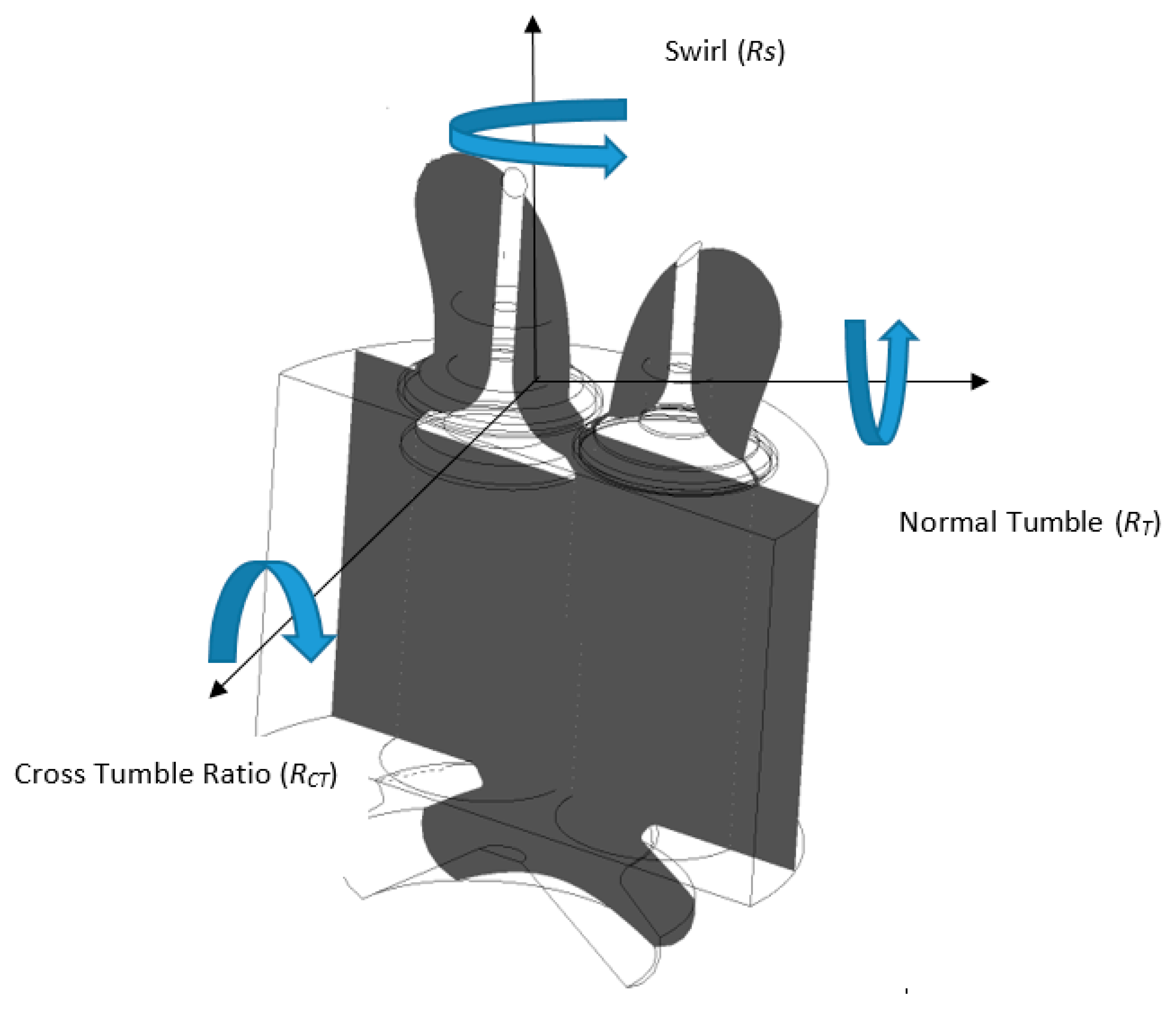
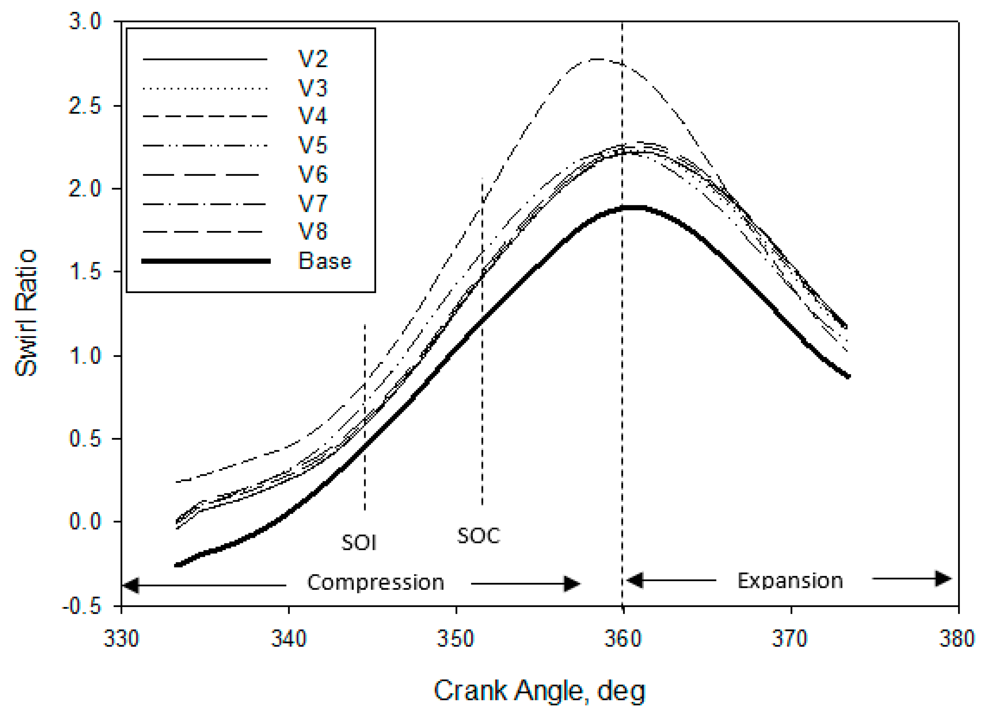
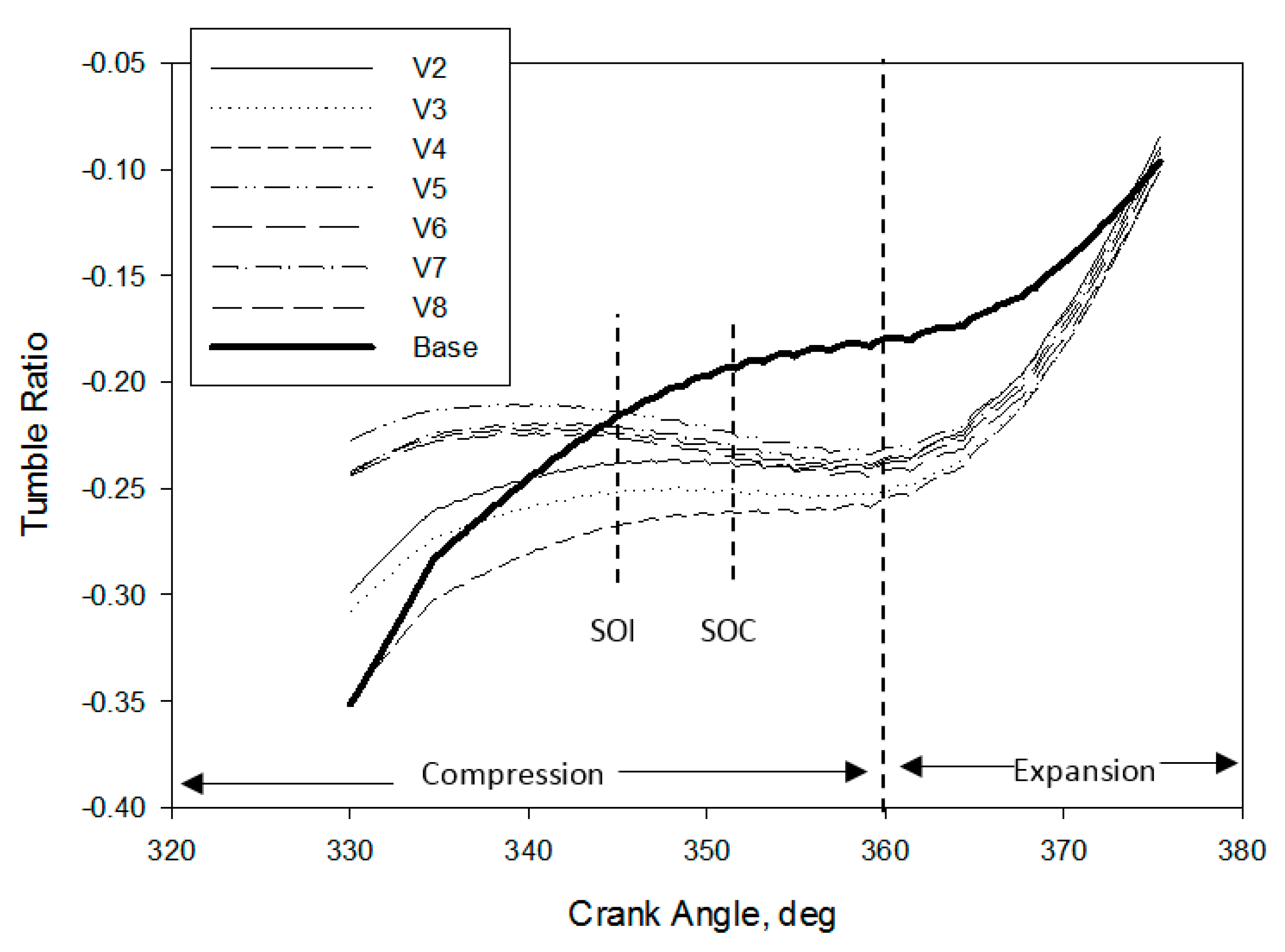
4.4. In-Cylinder Swirl, Tumble and Cross Tumble Ratio

One of the key factors that determine the large scale mixing of air-fuel during the intake and compression stroke is the in-cylinder airflow motion in the combustion chamber, especially in the velocity streamline. The three main components that affect the in-cylinder airflow motion are RS, RT, RCT are calculated from the crank angle engine stroke to the above mentioned designs. Figure 8 shows the orientation diagram for the definition of RS, RT and RCT; their directions will be discussed accordingly.
Figure 9 shows the RS of in-cylinder for different numbers of GVD against the crank angle before TDC. RS is defined as a rotation airflow around the swirl axis relative to the flow (around the cylinder axis) [37] and used to promote rapid combustion. High-magnitude in-cylinder RS encourages better air fuel mixing, breaks up more fuel molecules and improves engine performance. As can be seen from the graph, the RS increases due to higher airflow acceleration and is proportional to the crank angle; thus, the angular momentum is conserved at the time of compression before approaching TDC. According to the graph, during the expansion process, the declining trend is due to the reversal flow exiting from the piston and wall friction. However, the main focus was on SOI at 346° and SOC at 352°. The results imply that the utilization of GVD had improved the swirl flow generally and 4 vanes (V4) had shown about 35% swirl flow improvement compared to the original baseline in-cylinder swirl flow. Kim et al. [38] illustrated that from their photographic results, the flame size without the swirl control valve (SCV) was smaller than with SCV at 1.6° crank angle after SOI, due to strong swirl flow. Therefore, it’s confirmed that enhancing the swirl flow will benefit engine operation and can be manipulated for high viscous fuel, e.g., emulsified biofuel.
Figure 10 shows the RCT for different numbers of GVD against crank angle before TDC. RCT is defined as a rotational ratio of airflow on the cross tumble axis relative to the other axes [39]. As in RS, the negative or positive value of RCT is neglected as it is arbitrary, and depends on the magnitude obtained. It can be seen that the installation of GVD has increased the magnitude ratio of RCT. Nevertheless, RCT has a close correlation between RS and RT. Khalighi et al. [40] noted that in order to maximize RCT and RS and RT need to be maximized. Rabault et al. [41] reported that enhancing RCT assisted the premixed of air fuel mixture to become much better, indirectly achieve good combustion. As previously mentioned, emulsified biofuel increases the penetration length and shortens the cone angle. Therefore, with the correct number of vanes, RCT can significantly break up the length of penetration; which becomes wider during injection into the combustion chamber. Based on the figure, it can be clearly seen that the design of V4 is an appropriate GVD for producing homogeneous mixture during compression thus, the lateral flow of air is improved within the cylinder.
Figure 11 shows the RT for different numbers of GVD against crank angle before TDC. RT is defined as a ratio of rotational airflow around the tumble axis (orthogonal to the cylinder axis) [42]. The function of RT is generally to aid the flow of the molecular fuel to the wider area of the combustion chamber. RT also helps to maintain a uniform distribution of flow along the piston bowl. As can be seen from the graph, the high-magnitude of tumbles is clearly visible on all GVD models compared to the base model. Again, V4 and V3 of GVD show greater RT occurrence in the area of SOI and SOC. Therefore, V4 and V3 are able to generate higher RT, which can enhance the mixing process and improve engine operation which is fuelled with high viscous fuel. In addition, it also implies that incorporating GVD and SCC piston facilitates a strong lateral flow of air within the cylinder. The role of lateral flow function is to assist in spreading the atomization molecule fuel throughout the piston bowl, thereby offering sufficient time to combust and avoid deposition of residual carbon deposit. This has shown an agreement with the findings of Payri et al. [34], wherein it was inferred that the piston geometry had little influence on RT during the compression stroke. However, the piston bowl design and stronger in-cylinder lateral airflow had a significant effect; especially in the mean velocity field and turbulent zone near TDC, approaching at the early stage of the expansion stroke.

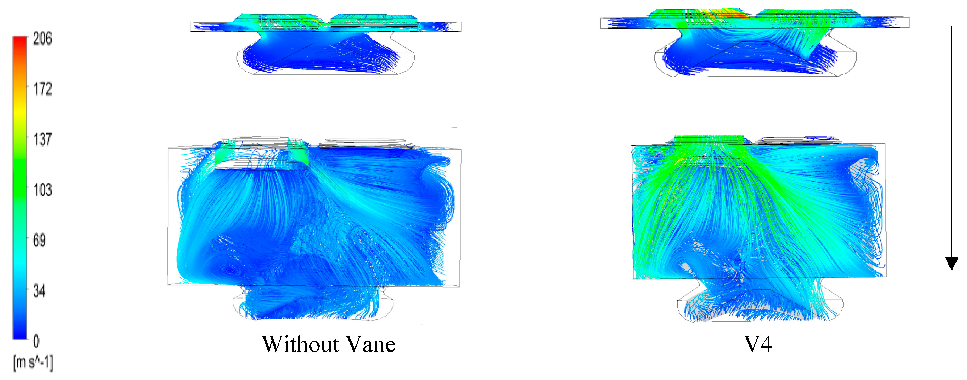
4.5. In-Cylinder Airflow Characteristics during Intake Stroke

The instantaneous streamline of the intake stroke at a crank angle of 10° and 90° after TDC is presented in Figure 12. For intake stroke at a crank angle of 10°, the airflow pattern was initially induced through a piston bowl. The V4 design, which had guided the airflow via vanes, shows the preliminary turbulent flow in the intake manifold before being induced into the combustion chamber. It also demonstrates the ability of the fluid to develop rotational motion in the cylinder and benefit in assisting the atomization of heavy molecules, i.e., emulsified biofuel. The intake stroke at crank angles of 90° shows the RS phenomena due to the influence of tumble flow. However, the engine without vanes (base) has shown low-velocity flow compared to the engine using vanes. These results were supported by Heywood [43], who suggested the consideration of the vortex flow during intake process, in order to enhance the turbulence intensity at the compression stage.

4.6. In-Cylinder Airflow Characteristics during Compression Stroke

Figure 13 shows the instantaneous streamline of the compression stroke at crank angles of 346° and 310°. At the time of compression stroke, when the volume tends to change as a result of compression, the density of air, temperature and pressure witnessed an increase. From Figure 11, a notable effect on the amplification of turbulent flow and the acceleration of air can be seen. The velocity of air was generally higher during cranking angle at a position of 310° for both the designs. However, the air velocity decreased gradually when it reached TDC. The SCC piston with V4 design showed uniform velocity in-cylinder flow on both sides at a crank angle of 346° (at SOI stage). It implied that the engine using vanes in their operation can produce a strong velocity of air, high turbulent flow and be able to transport heavy molecules of fuel, i.e., emulsified biofuel with the homogenous mixture. With the abilities mentioned above, the flame speed and the reliability of combustion for a very low air fuel ratio will be promoted.

4.7. In-Cylinder Pressure during Compression Stroke

The improvement of combustion efficiency is rely on the in-cylinder pressure inside the engine. Higher in-cylinder pressure value will benefited to the fuel penetration during spraying and aids to expend the cone angle which is necessary for application of higher viscous fuel. Figure 14 shows the variation of in-cylinder pressure without vane and with GVD V4. From the figure can be seen that, GVD model V4 produces an extra in-cylinder pressure compared to the without GVD. The area that built up pressure in the V4 model is at the near injection port area and obviously produced more pressure in the piston-bowl with the organized in-cylinder air flow throughout along the piston-bowl area. With this result, the higher in-cylinder pressure will definitely give more resistance to the injected fuel in term of friction to the air flow and consequently reduce the penetration length during injection.

5. Conclusions

Emulsified biofuel possesses a high potential to replace fossil fuel and to be used in the diesel engine. The similar properties of emulsified biofuel and fossil fuel enable this fuel to be used in the engine with minor modifications. However, emulsified biofuel is more viscous, less volatile and has heavy molecules that restrict to maximum evaporation of spraying. This phenomenon eventually deposits the carbon on the cylinder wall and piston head, piston ring sticking and resulted in incomplete combustion. Therefore, introducing GVD can improve and generate more swirl and tumble airflow to enhance the turbulent flow for extra-evaporating emulsified biofuel. The in-cylinder air flow characteristics of (RS), (RT), TKE and RCT were investigate and compared between the 7 models of GVD and base model of various vane numbers. Hence, based on the simulation result, the four numbers of vanes (V4) in GVD have shown the best performance in terms of TKE, RS, RT and RCT. The streamline compression stroke shows that V4 allows the air flow throughout piston-bowl to be more recognized, which enhanced the in-cylinder air flow velocity that expected could break up the length penetration during spraying process. For future work, the study will be extended and investigated using the strategy of combination of GVD with SCC piston and their effect of injection profile, structure of spraying and combustion characteristics using higher viscosity fuel such as emulsified biofuel application in the diesel engine.

Author Contributions

Conceptualization, M.F.H. and M.Y.I.; Methodology, M.F.H., M.K.A. M.Y.I. and S.S.; Experimentation, S.C.M., M.F.H. and T.Y.H.; Data analysis, M.F.H., K.A.S., and R.K.S.; Resources, M.Y.I. and M.F.H.; Writing—original draft preparation, M.F.H and M.K.A.; Writing, review and editing : Z.A.Z.A. All authors have read and agreed to the published version of the manuscript.

Funding

The authors would like to thank to Universiti Sains Malaysia (USM) on Research University Grant Scheme under Grant No. 1001/PBAHAN/8014006 and USM Fellowship RU (1001/CIPS/AUPE001) for supporting the research journey.

Conflicts of Interest

The authors declare no conflict of interest.

Nomenclature

English SymbolsDescriptionUnits
UThree dimensional flow velocities x,y and z directionsm/s
PPressurePa
TTemperatureK
tTimes
NEngine speedrpm
TTorqueN·m
mMasskg
LLitrel
h t o t Total enthalpyJ/kg
vVelocitym/s
vmaxMaximum velocitym/s
S M Momentum sourceN/m3
u Three-dimensional flowmm/s
RRadiusmm
lLengthmm
x,y,zCartesian coordinatesmm
Greek SymbolsDescriptionUnits
ρ Fluid densitykg/m3
ωAngular acceleration rad/s
λThermal conductivityW/m·K
θCrank angle degree-
τ Strain rate1/s
Gradient operator-
AbbreviationsDescription
IVOIntake valve open
IVCIntake valve close
EVOExhaust valve open
EVCExhaust valve close
GVDGuide Vane Design
SCCShallow depth re-entrance combustion chamber
IARCInternational Agency for Research on Cancer
RPORefine Palm Oil
SMMomentum Source
RTTumble Ratio
RSSwirl Ratio
RCTCross Tumble Ratio
TKETurbulence Kinetic Energy

References

  1. Reitz, R.D.; Duraisamy, G. Review of high efficiency and clean reactivity controlled compression ignition (RCCI) combustion in internal combustion engines. Prog. Energy Combust. Sci. 2015. [Google Scholar] [CrossRef] [Green Version]
  2. Al-attab, K.; Wahas, A.; Almoqry, N.; Alqubati, S. Biodiesel production from waste cooking oil in Yemen: A techno-economic investigation. Biofuels 2017, 8, 17–27. [Google Scholar] [CrossRef]
  3. Benbrahim-Tallaa, L.; Baan, R.A.; Grosse, Y.; Lauby-Secretan, B.; El Ghissassi, F.; Bouvard, V.; Guha, N.; Loomis, D.; Straif, K.; International Agency for Research on Cancer Monograph Working Group. Carcinogenicity of diesel-engine and gasoline-engine exhausts and some Nitroarènes. Pollut. Atmos. 2012, 13, 663–664. [Google Scholar] [CrossRef] [Green Version]
  4. IARC. Diesel and gasoline engine exhausts and some nitroarenes. In IARC Monographs Evaluation Carcinogenic Risks to Humans; IARC: Lyon, France, 2013. [Google Scholar]
  5. IARC. Diesel and gasoline engine exhausts. In IARC Monographs Evaluation Carcinogenic Risks to Humans; IARC: Lyon, France, 2012. [Google Scholar]
  6. Rai, R.; Glass, D.C.; Heyworth, J.S.; Saunders, C.; Fritschi, L. Occupational exposures to engine exhausts and other PAHs and breast cancer risk: A population-based case-control study. Am. J. Ind. Med. 2016, 59, 437–444. [Google Scholar] [CrossRef]
  7. Mauderly, J.L.; Seilkop, S.K. The National Environmental Respiratory Center (NERC) experiment in multi-pollutant air quality health research: II. Comparison of responses to diesel and gasoline engine exhausts, hardwood smoke and simulated downwind coal emissions. Inhal. Toxicol. 2014, 26, 668–690. [Google Scholar] [CrossRef]
  8. Mat Yasin, M.H.; Mamat, R.; Najafi, G.; Ali, O.M.; Yusop, A.F. Potentials of palm oil as new feedstock oil for a global alternative fuel: A review. Renew. Sustain. Energy Rev. 2017, 79, 1034–1049. [Google Scholar] [CrossRef] [Green Version]
  9. Agarwal, D.; Agarwal, A.K. Performance and emissions characteristics of Jatropha oil (preheated and blends) in a direct injection compression ignition engine. Appl. Therm. Eng. 2007, 27, 2314–2323. [Google Scholar] [CrossRef]
  10. Li, J.; Yang, W.M.; An, H.; Maghbouli, A.; Chou, S.K. Effects of piston bowl geometry on combustion and emission characteristics of biodiesel fueled diesel engines. Fuel 2014, 120, 66–73. [Google Scholar] [CrossRef]
  11. Hamid, M.F.; Idroas, M.Y.; Sa’ad, S.; Bahri, A.J.S.; Sharzali, C.M.; Zainal, Z.A. Numerical investigation of in-cylinder air flow characteristic improvement for Emulsified biofuel (EB) application. Renew. Energy 2018, 127, 84–93. [Google Scholar] [CrossRef]
  12. Ali, O.M.; Mamat, R.; Abdullah, N.R.; Abdullah, A.A. Analysis of blended fuel properties and engine performance with palm biodiesel-diesel blended fuel. Renew. Energy 2015, 86, 59–67. [Google Scholar] [CrossRef] [Green Version]
  13. Ren, Y.; Li, X.G. Numerical study on the combustion and emission characteristics in a direct-injection diesel engine with preheated biodiesel fuel. J. Automob. Eng. 2011, 225, 531–543. [Google Scholar] [CrossRef]
  14. Cheng, C.H.; Cheung, C.S.; Chan, T.L.; Lee, S.C.; Yao, C.D.; Tsang, K.S. Comparison of emissions of a direct injection diesel engine operating on biodiesel with emulsified and fumigated methanol. Fuel 2008, 87, 1870–1879. [Google Scholar] [CrossRef]
  15. Khond, V.W.; Kriplani, V.M. Effect of nanofluid additives on performances and emissions of emulsified diesel and biodiesel fueled stationary CI engine: A comprehensive review. Renew. Sustain. Energy Rev. 2016, 59, 1338–1348. [Google Scholar] [CrossRef]
  16. Mofijur, M.; Rasul, M.G.; Hyde, J.; Azad, A.K.; Mamat, R.; Bhuiya, M.M.K. Role of biofuel and their binary (diesel-biodiesel) and ternary (ethanol-biodiesel-diesel) blends on internal combustion engines emission reduction. Renew. Sustain. Energy Rev. 2016. [Google Scholar] [CrossRef] [Green Version]
  17. Agarwal, A.K.; Dhar, A.; Gupta, J.G.; Kim, W., II; Choi, K.; Lee, C.S.; Park, S. Effect of fuel injection pressure and injection timing of Karanja biodiesel blends on fuel spray, engine performance, emissions and combustion characteristics. Energy Convers. Manag. 2015, 91, 302–314. [Google Scholar] [CrossRef]
  18. Taib, N.M.; Mansor, M.R.A.; Mahmood, W.M.F.W. Modification of a direct injection diesel engine in improving the ignitability and emissions of diesel-ethanol-palm oil methyl ester blends. Energies 2019, 12, 2644. [Google Scholar] [CrossRef] [Green Version]
  19. Kim, H.Y.; Ge, J.C.; Choi, N.J. Effects of fuel injection pressure on combustion and emission characteristics under low speed conditions in a diesel engine fueled with palm oil biodiesel. Energies 2019, 12, 3264. [Google Scholar] [CrossRef] [Green Version]
  20. Abed, K.A.; Gad, M.S.; El Morsi, A.K.; Sayed, M.M.; Elyazeed, S.A. Effect of biodiesel fuels on diesel engine emissions. Egypt. J. Pet. 2019, 28, 183–188. [Google Scholar] [CrossRef]
  21. Bari, S.; Saad, I. Performance and emissions of a Compression Ignition (CI) engine run with biodiesel using guide vanes at varied vane angles. Fuel 2015, 143, 217–228. [Google Scholar] [CrossRef]
  22. Bari, S.; Saad, I. CFD modelling of the effect of guide vane swirl and tumble device to generate better in-cylinder air flow in a CI engine fuelled by biodiesel. Comput. Fluids 2013, 84, 262–269. [Google Scholar] [CrossRef]
  23. Bae, C.; Kim, J. Alternative fuels for internal combustion engines. Proc. Combust. Inst. 2017. [Google Scholar] [CrossRef]
  24. Mallick, M.; Kumar, A.; Tamboli, N.; Kulkarni, A. Study on drag coefficient for the flow past a cylinder. Physics 2014, 5, 301–306. [Google Scholar]
  25. Hwang, J.; Qi, D.; Jung, Y.; Bae, C. Effect of injection parameters on the combustion and emission characteristics in a common-rail direct injection diesel engine fueled with waste cooking oil biodiesel. Renew. Energy 2014, 63, 9–17. [Google Scholar] [CrossRef]
  26. Yadav, S.P.R.; Saravanan, C.G. Engine characterization study of hydrocarbon fuel derived through recycling of waste transformer oil. J. Energy Inst. 2015, 88, 386–397. [Google Scholar] [CrossRef]
  27. Voutchkov, I.; Keane, A.; Shahpar, S.; Bates, R. (Re-) Meshing using interpolative mapping and control point optimization. J. Comput. Des. Eng. 2018, 5, 305–318. [Google Scholar] [CrossRef]
  28. Blanchard, G.; Loubère, R. High order accurate conservative remapping scheme on polygonal meshes using a posteriori MOOD limiting. Comput. Fluids 2016, 136, 83–103. [Google Scholar] [CrossRef] [Green Version]
  29. ANSYS Inc. ANSYS Fluent Theory Guide; Release 18.2; ANSYS Inc.: Ganonsburg, PA, USA, 2013. [Google Scholar]
  30. Rahman, M.M.; Mohammed, M.K.; Bakar, R.A. Effect of air fuel ratio on engine performance of single cylinder port injection hydrogen fueled engine: A numerical study. In Proceedings of the International MultiConference of Engineers and Computer Scientists, Hong Kong, China, 18–20 March 2009. [Google Scholar]
  31. Rajak, U.; Nashine, P.; Singh, T.S.; Verma, T.N. Numerical investigation of performance, combustion and emission characteristics of various biofuels. Energy Convers. Manag. 2018, 156, 235–252. [Google Scholar] [CrossRef]
  32. Baumann, M.; di Mare, F.; Janicka, J. On the validation of large eddy simulation applied to internal combustion engine flows part II: Numerical analysis. Flow Turbul. Combust. 2014, 92, 299–317. [Google Scholar] [CrossRef]
  33. Stock, H.W.; Haase, W. Navier-Stokes airfoil computations with e sup N transition prediction including transitional flow regions. AIAA J. 2012, 38, 2059–2066. [Google Scholar] [CrossRef]
  34. Payri, F.; Benajes, J.; Margot, X.; Gil, A. CFD modeling of the in-cylinder flow in direct-injection Diesel engines. Comput. Fluids 2004, 33, 995–1021. [Google Scholar] [CrossRef]
  35. Prasad, B.V.V.S.U.; Sharma, C.S.; Anand, T.N.C.; Ravikrishna, R.V. High swirl-inducing piston bowls in small diesel engines for emission reduction. Appl. Energy 2011, 88, 2355–2367. [Google Scholar] [CrossRef]
  36. Miles, P.; Choi, D.; Megerle, M.; Ewert, B.R.; Reitz, R.; Lai, M.C.; Sick, V. The influence of swirl ratio on turbulent flow structure in a motored HSDI diesel engine—A combined experimental and numerical study. SAE Tech. Pap. 2010. [Google Scholar] [CrossRef]
  37. Hamid, M.F.; Idroas, M.Y.; Basha, M.H.; Saad, S.; Mat, S.C.; Khalil, M.; Zainal, Z.A. Numerical study on dissimilar guide vane design with SCC piston for air and emulsified biofuel mixing improvement. Chemistry 2016. [Google Scholar] [CrossRef] [Green Version]
  38. Kim, K.; Chung, J.; Lee, K.; Lee, K. Investigation of the swirl effect on diffusion flame in a direct-injection (DI) diesel engine using image processing technology. Energy Fuels 2008, 22, 3687–3694. [Google Scholar] [CrossRef]
  39. Buhl, S.; Gleiss, F.; Kohler, M.; Hartmann, F.; Messig, D.; Brucker, C.; Hasse, C. A combined numerical and experimental study of the 3D tumble structure and piston boundary layer development during the intake stroke of a gasoline engine. Flow Turbul. Combust. 2017, 98, 579–600. [Google Scholar] [CrossRef] [Green Version]
  40. Khalighi, B. Study of the intake tumble motion by flow visualization and particle tracking velocimetry. Exp. Fluids 1991, 10, 230–236. [Google Scholar] [CrossRef]
  41. Rabault, J.; Vernet, J.A.; Lindgren, B.; Alfredsson, P.H. A study using PIV of the intake flow in a diesel engine cylinder. Int. J. Heat Fluid Flow 2016. [Google Scholar] [CrossRef] [Green Version]
  42. Wang, T.; Liu, D.; Tan, B.; Wang, G.; Peng, Z. An investigation into in-cylinder tumble flow characteristics with variable valve lift in a gasoline engine. Flow Turbul. Combust. 2015, 94, 285–304. [Google Scholar] [CrossRef]
  43. Heywood, J.B. Internal Combustion Engine Fundementals; McGraw-Hill Education: New York, NY, USA, 1998. [Google Scholar]
Figure 1. GVD design. (a) Front view; (b) Side view**.
Processes 08 00439 g001
Figure 2. Schematic diagram for shallow depth re-entrance combustion chamber (SCC) piston bowl geometry design (all in mm) [11]. Reproduced with permission from Hamid et al., (Renewable Energy); published by (Elsevier), (2018).
Processes 08 00439 g002
Figure 3. Schematic diagram of modelling engine Yanmar L70AE-DTM configuration.
Processes 08 00439 g003
Figure 4. The engine Yanmar L70 setup test rig.
Processes 08 00439 g004
Figure 5. In-cylinder pressure against crank angle (degree).
Processes 08 00439 g005
Figure 6. Computational domain during (a) intake CA at 45° (b) compression CA at 300° (c) exhaust CA at 630°.
Processes 08 00439 g006
Figure 7. TKE against crank angle (θ).
Processes 08 00439 g007
Figure 8. Orientation diagram for swirl, tumble and cross tumble components.
Processes 08 00439 g008
Figure 9. Swirl ratio against crank angle (θ).
Processes 08 00439 g009
Figure 10. Cross tumble ratio against crank angle (θ).
Processes 08 00439 g010
Figure 11. Tumble ratio against crank angle.
Processes 08 00439 g011
Figure 12. The computed streamline intake stroke crank angle at 10° (top) and 90° (bottom) showing the swirl and tumble airflow structure.
Processes 08 00439 g012
Figure 13. The computed streamline compression stroke crank angle at 346° (top) and 310° (bottom).
Processes 08 00439 g013
Figure 14. The in-cylinder pressure during compression stroke crank angle at 346° (top) and 310° (bottom).
Processes 08 00439 g014
Table 1. Specification of guide vane design (GVD).
NoParameterValue
1Number of Vanes (N)Base, 2,3,4,5,6,7,8
2Vane Length (l)30 mm
3Width of vane0.5 mm
4Vane Height (Hv)0.6 R
5Vane twist angle (θ)35°
6Angle of incidence90°
Table 2. Technical specifications of Yanmar L70AE CI engine generator.
Engine ParametersDetails
Engine ModelYanmar L70AE
Bore78 mm
Stroke62 mm
Compression ratio19.1
Number of cylinder1
Engine weight36 kg
Type of injectionDirect inject
Fuel injection pressure19.6 Mpa
Displacement0.296 L
High idle speed3600 rpm
Max. rated power4.9 kW @ 3600 rpm
Injection timing14° ± 1° BTDC
IntakeNaturally aspirated
CoolingForced air
LubricationForced lubrication with trochoid pump
Direct of rotationCounter clockwise
Starting systemElectric start/Recoil start
IVO, IVC155°, 59°
EVO, EVC−59°, 155°
Table 3. Summary of grid independence test (GIT).
Case12345
Elements average cylinder102,343254,223302,309371,424447,573
Pressure2.082 × 1063.099 × 1063.153 × 1063.153 × 1063.153 × 106

