Abstract
The aim of the present paper is to investigate the deformation–stress state of fillings of V-shaped tooth defects by finite element analysis (FEA). Two different materials are used—auto-cured resin-reinforced glass-ionomer cement (GIC) and flowable photo-cured composite (FPC). Two materials are placed into the cavity in one portion, as before the application of the composite the cavity walls are covered with a thin adhesive layer. Deformations and equivalent von Mises stresses are evaluated by FEA. Experimental study of micro-leakage is performed. It is established that there is an analogous non-homogeneous distribution of equivalent Von Mises stresses at fillings of V-shaped defects, made with GIC and FPC. Maximum stresses are generated along the boundaries of the filling on the vestibular surface of the tooth and at the bottom of the filling itself. Values of equivalent Von Mises stresses of GIC fillings are higher than that of FPC. Magnitude and character of deformation distribution at GIC and FPC fillings are similar—deformation is maximum along the vestibular surface of the filling and is 0.056 and 0.053 mm, respectively. In FPC fillings, the adhesive layer, located along the cavity/filling boundary, is characterized with greatest strain. The experimental study of micro-leakage has confirmed the adequacy of models used in FEA.
1. Introduction
V-shaped defects are non-carious cervical lesions on hard tooth tissues (HTT), which have a specific etiology, pathogenesis and clinical picture. Characteristic of this disease is that the defects are located mainly on the vestibular surface of the teeth, most often on the first premolars. Their deepening leads to the destruction of the dental crown as well as diseases of the pulp and periodontium. The anatomic shape of the teeth is disturbed. The treatment of V-shaped defects is a challenge for the dental practitioner because of the difficulties associated with holding the obturation over time, which requires a good knowledge of the restorative options and the sound choice of a suitable material.
In the case of medium and deep V-shaped defects, due to abnormalities in the anatomical shape of the teeth and deterioration of the aesthetic appearance as well as presence of hyperesthesia and functional disorders when the bottom of the lesion is close to the pulp, their restoration is required. Depending on the size of the defect and its location, a suitable material is selected. Today, plastic materials with a transparency and color similar to those of the natural enamel are used. According to the defect localization, coronary or cervical glass-ionomer cements, modified glass-ionomer cements, composite materials or compomers are recommended [1,2,3,4,5].
It is common practice for V-shaped defects to be filled with glass-ionomer cement (GIC) because they show a very good bond with the dentin without requiring additional adhesion. In the in vitro study of I.P. Ichim et al. [6], two techniques for filling V-shaped defects on the buccal surface were selected—insertion of the entire amount of material (GIC) at once and an incremental technique (GIC and composite material). Different investigations show that not all contemporary materials are appropriate for the treatment of all kinds non-carious lesions, because they exhibit a modulus of elasticity of 10.2 GPa. It has been found that the most suitable material for cervical restorations needs to be more flexible and with relatively low modulus of elasticity—about 1 GPa. Resin-modified glass-ionomer cements (RMGIC) were created in 1988 and since 1995 have been converted to enamel–dentin adhesives [7,8,9]. They show less restoration strength than the latest generation of adhesive systems, but higher than the conventional GIC.
The effectiveness of the composite material for treatment of V- shaped defects depends on the success of the bonding agents. If the adhesion of the composite to the enamel and dentin is not strong enough, a gap is formed between them, leading to sensitivity of the teeth, loss of retention and increased risk of secondary caries.
Scientific investigations of different adhesive systems—three-step etch-and-rinse, two-step etch-and-rinse, two-step self-etch, one-step self-etch [10,11]—show good results for adhesion. The cervical restoration, made with etch-and-rinse adhesive, show a better retention level than the all-in-one adhesive [12] with using of nano-hybrid composite. The retention rate of obturations is 82% and 75% for 6 months and 77% and 62% for 12 months. For 24 months, the retention level decreases to 69% for the etch-and-rinse adhesive and 49% for the all-in-one adhesive. There are no significant changes in color and marginal adaptation between the adhesive systems. None of the restorations have secondary caries or display any loss in anatomical shape or texture changes. Sabine May et al. [13] used two types of flowable composite to maintain V-shaped tooth defects. Fifty patients were treated with both composites and the results were monitored for 18 and 36 months. A 95.8% success rate for 36 months was found.
In recent years, simulation analysis has been used very often in the study of dental constructions, because it gives faster and relatively more reliable results than in clinical experiments when predicting complex cases of recovery [14,15,16]. The biomechanical behavior of different types of dental construction, such as crowns, bridges, implants, fillings, implant/bone surfaces, obturation/HTT etc., made of different materials or combinations of materials—metals, alloys, porcelain, metal-ceramics, composites and polymers—can be investigated with the help of the method of finite elements analysis (FEA) [16,17,18]. The laboratory simulation is mainly applied to investigate the biomechanical behavior of complex dental constructions and to understand the reasons for their deformations and failure [15,16,19,20].
Due to the great variety of direct restorative materials in dentistry nowadays, most research targets clinical investigations and in vitro experiments. The results can help one to evaluate the applicability of the particular restorative material for the specific purpose. However, the reasons, determining the behavior of dental constructions and materials can be revealed by simulations using numerical modelling.
The aim of the present paper is to study the stresses and deformations generated during the setting process of fillings of V-shaped defects made with GIC and flowable photo-cured composite (FPC) using FEA. The distribution and magnitude of the equivalent Von Mises stresses, displacements and strains in the tooth tissue and the filling itself are investigated. To validate the results, an in vitro experimental study of the micro-leakage of obturations, made with both materials, is performed.
2. Materials and Methods
2.1. Numerical Modelling by FEA
Two teeth (tooth 11 and tooth 15 according to the ISO System by the World Health Organization) were scanned with a 3Shape laboratory scanner (3Shape A/S, Denmark). Virtual models in .stl file format were obtained, which were then converted to .part format of the SolidWorks software. On the vestibular surface of each tooth, one cavity of the size of the actual experiment was made at a distance of 1.25 mm from the cement/enamel border. As the V-shaped defects were located in the areas of the teeth with thin enamel, and the dentin was considered as a “gold standard” [21] when developing new dental composites, in the simulations the enamel was eliminated and only dentin was used as the tooth material. The cavity of tooth 11 was filled with GIC, while that of tooth 15 was filled with FPC.
In order to investigate the effect of the shrinkage of GIC and FPC on the stress-deformation state of the model, the analogy of volume reduction during the solidification process of the filling materials and during the cooling process was used. The capabilities of the SolidWorks Simulation software were used to analyze deformations and stresses due to temperature differences. Three different temperatures were applied: 19.99, 19.98 and 19.97 °C for shrinkage of 1%, 2% and 3%, respectively.
The virtual model of tooth 11 consisted of two parts, a GIC filling and a tooth of dentin (Figure 1a), while that of tooth 15 represented a system of three elements: tooth/30-µm adhesive layer/FPC filling (Figure 2a). The mesh, used in the simulations, is shown in Figure 1b and Figure 2b. Standard solid mesh of high quality and tetragonal elements with 0.1 mm average size was used. The total number of the finite elements in GIC simulation was 986,861 and the number of the total nodes was 1,377,670. These parameters for FPC simulation are 1,170,403 and 1,629,798, respectively. Concerning the boundary conditions, the teeth were fixed at the bottom of the root, as shown in Figure 1a and Figure 2a. In the numerical modeling, it was assumed that there was complete continuous contact between the tooth and the GIC filling and the three elements of the system in the case of FPC filling.
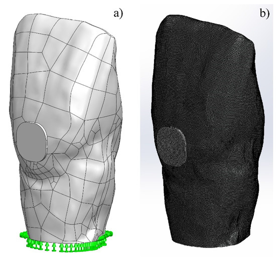
Figure 1.
Virtual model of tooth 11: (a) fixed tooth with filling of glass-ionomer cement (GIC); (b) simulation mesh used.
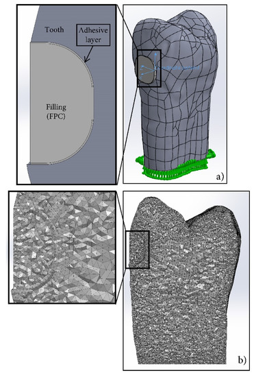
Figure 2.
Virtual model of tooth 15: (a) fixed tooth with filling of flowable composite; (b) mesh used in simulation.
In the cavity, filled with GIC, the mechanical properties of the materials were set under the conditions of linear elastic isotropic strengthening. In the case of the cavity, filled with FPC, only the mechanical properties of the tooth and the adhesive layer were set under the above-mentioned conditions. Meanwhile, for the FPC filling, a model of linear elastic orthotropic strengthening was used, allowing the introduction of various physical-mechanical properties in the three directions. In this way, the shrinkage of FPC in the direction of the lamp, irradiating the filling material, was simulated. Unlike the actual photopolymerization process, which is non-homogeneous along the depth of the filling, numerical modeling was performed with the assumption of a uniform shrinkage along the X-axis due to the limitations of the software used. The values of modulus of elasticity and Poisson’s ratio of the materials used are given in Table 1. The simulations were performed with the assumption of a homogeneous structure of the materials of filling and the adhesive layer, as well as of the dentin of the tooth.

Table 1.
Data for materials used in the simulations [22,23,24,25,26,27,28].
In both cases, a static task for linear strength analysis of the model is generated in a SolidWorks Simulation environment. During the simulation analysis, the Von Mises equivalent stresses, displacements and strains in the process of shrinkage of the fillings of V-shape defects made with GIC and FPC were evaluated.
2.2. In-Vitro Investigation of Micro-Leakage
Twenty-four freshly extracted human teeth (incisors, canines, premolars) were used to produce V-shaped defects on the vestibular surface of the teeth in the area of the enamel-cement border with the following shapes and average sizes: length L= 2.5 mm × width B = 2.5 mm × depth d = 1.3 mm.
The teeth were divided into two groups, with 12 teeth in each. The teeth of the first group were filled with auto-cured resin-reinforced glass-ionomer restorative cement FUJI VIII GP (GC Corporation, Japan), the second group with flowable light-cured composite with lower viscosity Estelite Flow Quick - High Flow (Tokuyama Dental Corporation inc., Japan). Prior to the application of the restorative material, all cavities were processed according to the manufacturer’s recommendations. In the first group, after the cavity preparation and processing, the GIC was applied in one portion. The cavities of the second group were treated with 37% orthophosphoric acid for 40 s, after which they were thoroughly washed with a water-air jet. Self-etching adhesive Adhese Universal (Ivoclar Vivadent AG, Liechtenstein) was applied along the entire surface of the enamel and dentin of the cavity and photopolymerized for 20 s. The cavity was then filled with a flowable composite, pressed with celluloid tape and photopolymerized for 10 s.
All samples were subjected to thermal cycling in the following mode: 500 cycles, temperature 5–50 °C, holding time 15 s [29]. The teeth, with the exception of the cavities, were then isolated with contrast lacquer, placed in a dye, 2% methylene blue solution, for 8 h and thoroughly washed.
An examination of the filled cavities was done with the Olympos SZ51 optical microscope. The degree of micro-leakage was evaluated by measuring the depth of dye penetration between the filling and the tooth walls.
3. Results
3.1. Numerical Modelling by FEA
Figure 3 shows the distribution of the equivalent Von Mises stresses on the vestibular surface of tooth 11 and tooth 15, filled with GIC and FPC, respectively. It can be seen that the equivalent stresses are generated mainly in the dentin of the tooth at the beginning of the setting process (1% shrinkage).
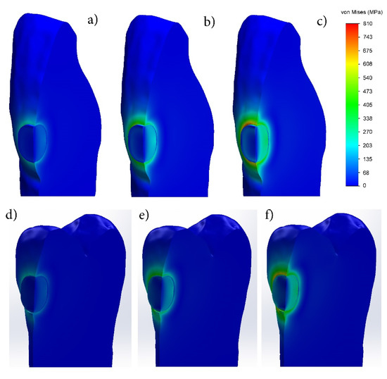
Figure 3.
Distribution of equivalent Von Mises stresses during setting process of fillings made with: (a–c) glass-ionomer cement; (d–f) flowable photo-cured composite (FPC). (1% shrinkage—(a,d); 2% shrinkage—(b,e); 3% shrinkage—(c,f)).
During the setting process of the fillings made of the two materials, the equivalent stresses increase with shrinkage increase and reach their maximum value at the end of the process. After final curing, in a maximum shrinkage of 3%, their distribution along the periphery of the filling is uneven. The highest equivalent stresses are observed at the rounded corners and the relatively lower ones in the straight sectors, which indicates the influence of the cavity shape.
The study of the equivalent stresses in depth shows that their distribution is non-homogeneous, both in the dentin of the tooth and in the filling itself (Figure 3). Regardless of the shrinkage ratio, their values are highest on the vestibular surface in the dentin at the edge of the filling. Increasing the shrinkage up to 3% leads to an increase in the equivalent stresses in the dentin at the edge of the obturation, reaching 810 and 705 MPa in the GIC and FPC, respectively, while in the dentin near the bottom of the filling they remain lower (203–270 MPa in the FPC). The stress distribution in the fillings of GIC and PFC is similar—they are smallest in the surface layer, increase with the distance to the deepest zone and reach their maximum value. At 3% shrinkage, the maximum stresses at the bottom of the GIC filling are 470–540 MPa, while at the FPC filling they are significantly lower—270–338 MPa. As the technique for preparation of the FPC filling differs from the GIC one, in this case the adhesive layer used between the dentin and FPC is clearly seen. In the adhesive layer, higher equivalent stresses in the range of 203–270 MPa appear only at 3% shrinkage. They are distributed not along the entire depth of the obturation, but only at about 30% distance from the vestibular surface.
The displacements in the processes of setting and photopolymerization of GIC and FPC fillings, respectively, are shown in Figure 4. It can be clearly seen that in both cases, the surface layer of the filling is subjected to maximum deformation, and it increases with increasing the shrinkage. In a maximum shrinkage of 3%, the displacement along the vestibular surface reaches 0.056 mm in the GIC and 0.053 mm in the FPC. In both materials, the deformation decreases with distance from the surface to the bottom of the filling.
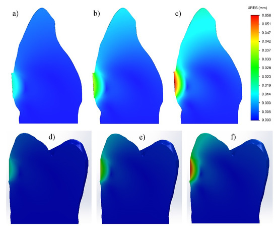
Figure 4.
Displacement during setting process of fillings made with: (a–c) glass-ionomer cement; (d–f) flowable photo-cured composite. (1% shrinkage—(a,d); 2% shrinkage—(b,e); 3% shrinkage—(c,f)).
The investigation of the strain has shown that at the GIC filling, it is located along its periphery—in the dentin of the tooth and the GIC of the filling (Figure 5a–c) and increases with shrinkage increase. At maximum shrinkage, the strain is uneven along the periphery, with larger values at the rounded corners and with smaller values in the linear sectors. In the FPC filling (Figure 5d–f), the strain is highest in the adhesive layer located along the cavity/filling boundary and increases with increasing the shrinkage of the restorative material.
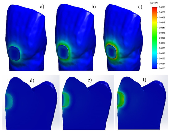
Figure 5.
Strain during setting process of fillings made with: (a–c) glass-ionomer cement; (d–f) flowable photo-cured composite. (1% shrinkage—(a,d); 2% shrinkage—(b,e); 3% shrinkage—(c,f)).
3.2. In-Vitro Investigation of Micro-Leakage
During the experiment, it was found that the V-shaped defects, filled with FPC, have a lower micro-leakage (24.49%) than those filled with GIC (38.02%). In the GIC fillings, the dye had penetrated more than one third of the depth of the obturation (Figure 6); whereas, in the case of teeth filled with FPC, only a slight penetration of dye was observed, mainly in the cervical region (indicated by arrows on the picture of Figure 7).
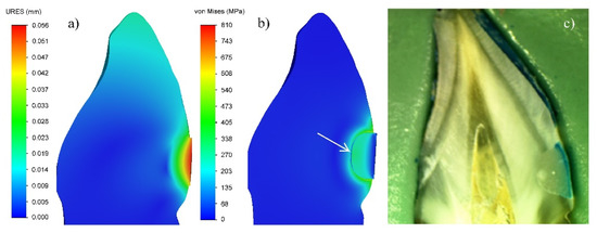
Figure 6.
GIC filling of tooth cavity: (a) Displacement in the zone of filling; (b) Von Mises equivalent stresses; (c) Micro-leakage. (3% shrinkage).
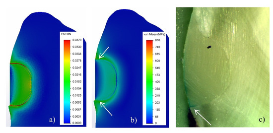
Figure 7.
Filling of tooth cavity made with FPC: (a) Strain in the zone of filling; (b) Von Mises equivalent stresses; (c) Micro-leakage. (3% shrinkage).
4. Discussion
4.1. V-Shaped Defects Filled with GIC
The analysis of the equivalent stresses and deformations has shown that their non-homogeneous distribution in the GIC filling is due to the peculiarities of the tooth/filling system. Since the vestibular surface of the obturation does not come into contact with the tooth, and there is a complete continuous contact between the other surfaces of the tooth and the filling, in the process of cement setting, the greatest deformation will occur in the surface layer of the obturation (Figure 4a–c). This will lead to the relaxation of the stresses in this zone. The full continuous contact with the hard tooth tissues impedes the deformation of the material along the depth of the filling volume and leads to an increase in the stresses in this region during the shrinkage process (Figure 3a–c). The modulus of elasticity of the tooth dentin is about 2.5 times higher than that of the GIC used for the filling (Table 1). This determines lower deformation and, accordingly, higher equivalent stresses on the vestibular surface of the tooth along the boundary with the filling. It is clearly seen in Figure 3c that the values of the equivalent stresses in the dentin are maximal at almost half of the depth of the obturation. When these values exceed the adhesion strength of the GIC to the dentin, which is relatively low—5.8 MPa (Table 1)—then there is an opportunity for the detaching of the cement from the cavity walls. In this way, gaps between the tooth and the filling will occur, creating conditions for micro-leakage of fluids (Figure 6).
The results obtained in the experimental investigation of GIC fillings show a micro-leakage of 38% along the depth of the cavities. These data correlate very well with the stress distribution along the depth of the filling in the numerical modeling with FEA (Figure 6). In spite of the high values of the stresses resulting from the use of an analogue of the shrinkage process in the simulation analysis, the model used gives a grounded explanation of the reasons for the relatively high micro-leakage. Therefore, the experiment has confirmed the adequacy of the model used in the simulation analysis.
4.2. V-Shaped Defects Filled with FPC
In an investigation of the deformation-stress state of cavities, filled with dental composites, in addition to the features of the tooth/filling system, the characteristics of the materials used and the specificity of their setting process must be taken into account. Since in the experimental study, a thin adhesive layer is applied on the entire surface of the cavity, the virtual model for simulations consists of three components: the tooth (made of dentin), the adhesive layer, and the filling of a flowable light-cured composite. The comparison of their modulus of elasticity shows the following relation: 19–4.85–9.9 GPa, respectively. Due to the large difference in the modulus of elasticity, the highest equivalent stresses occur in the dentin along the vestibular surface at the boundary with the filling (Figure 3d–f). Since there is an adhesive layer with a low modulus of elasticity between the composite and the cavity walls, it deforms in the shrinkage process of FPC (Figure 5d–f) and leads to the relaxation of the stresses in both the dentin and the filling material. As a result, the equivalent stresses at the tooth-filling boundary are lower than those in the GIC obturation. Due to the deformation of the adhesive layer, stresses in it are observed only in the maximum of 3% shrinkage (Figure 3f).
The deformation in the FPC filling is uneven in depth (Figure 4d–f) not only because of the fact that the lack of contact on the vestibular surface facilitates the shrinkage, but also because of the specificity of the photopolymerization process. In this case, the degree of polymerization (respectively shrinkage) depends on the light intensity, which is strongest on the surface [30], leading to larger shrinkage in the surface areas and less in depth. Due to the complexity of simulation of this type of process with FEA, it is assumed that the model of the FPC filling is of a linearly elastic orthotropic type. Therefore, in the process of numerical modeling, it is assumed that the shrinkage should be performed uniformly only along the X-axis. These two reasons predetermine the non-homogeneous distribution of the stresses in the volume of the FPC filling, with the lowest along the vestibular surface and the highest at the bottom. Due to the presence of an intermediate adhesive layer with a low modulus of elasticity, which in this case serves as a buffer [2,3,31,32], the stresses at the bottom of the FPC filling are almost two times lower than those of the GIC.
Since the bond between the adhesive and the composite is chemical and that between the HTT and the adhesive layer is micromechanical, it is expected that the bond at the adhesive–dentin boundary will be broken when the stresses exceed the adhesion strength of 35 MPa (Table 1). Numerical modeling has shown that stresses above this value are obtained only in the final 3% shrinkage of FPC (Figure 3d–f), as their maximum values reach about 30% of the depth of filling. This determines the lower micro-leakage value (24.49%) compared to the GIC fillings (38.08%) and correlates well with the results obtained in the experimental study.
The model used in the simulation analysis provides an adequate explanation of the reasons for the lower micro-leakage in V-shaped defects filled with FPC. On the one hand, the elastic adhesive layer has a positive effect, which leads to the relaxation of the stresses along the cavity/composite boundary, and on the other, the specificity of the photopolymerization process and, as a result, the inhomogeneous shrinkage in depth of the filling.
5. Conclusions
The deformation–stress state of V-shaped tooth defects filled with two different materials, glass-ionomer cement and flowable composite, is investigated by numerical modeling using FEA. The results are validated by an in vitro investigation of the micro-leakage of the fillings.
It is established that there is analogous non-homogeneous distribution of Von Mises equivalent stresses at the fillings of V-shaped defects, made with GIC and FPC. The maximum stresses are generated along the boundary of the filling on the vestibular surface of the tooth and at the bottom of the filling itself. The values of Von Mises equivalent stresses of GIC fillings are higher than that of FPC.
The magnitude and character of the deformation distribution at GIC and FPC fillings are similar—the displacement is maximum along the vestibular surface of the filling and is 0.056 and 0.053 mm, respectively. The strain in FPC fillings is greatest in the adhesive layer, located along the cavity/filling boundary.
The results of the FEA provide an adequate explanation of the reasons for the lower micro-leakage of the V-shaped defects filled with flowable composite. Therefore, the experiment has confirmed the adequacy of the models used in the simulation analysis.
Author Contributions
Conceptualization, T.D.; methodology, T.D., T.V., V.H.; FEA, T.V.; in-vitro investigation, V.H.; results analysis, T.D.; writing—original draft preparation, T.D., T.V., V.H.; writing—review and editing, V.P.; supervision, V.P. All authors have read and agreed to the published version of the manuscript.
Funding
This research received no external funding.
Acknowledgments
The simulation analysis was done with the help of Assoc. Prof. Diyan Dimitrov from the Department of Mechanics and Machine Elements at Technical University of Varna.
Conflicts of Interest
The authors declare no conflict of interest.
References
- Ichim, I.P.; Schmidlin, P.R.; Li, Q.; Kieser, J.A.; Swain, M.V. Restoration of non-carious cervical lesions: Part II. Restorative material selection to minimize fracture. Dent. Mater. 2007, 23, 1562–1569. [Google Scholar] [CrossRef] [PubMed]
- Kemp-Scholte, C.M.; Davidson, C.L. Complete marginal seal of Class V resin composite restorations effected by increased flexibility. J. Dent. Res. 1990, 69, 1240–1243. [Google Scholar] [CrossRef] [PubMed]
- Kemp-Scholte, C.M.; Davidson, C.L. Marginal integrity related to bond strength and strain capacity of composite resin restorative systems. J. Prosthet. Dent. 1990, 64, 658–664. [Google Scholar] [CrossRef]
- Li, Q.; Jepsen, S.; Albers, H.K.; Eberhard, J. Flowable materials as an intermediate layer could improve the marginal and internal adaptation of composite restorations in Class-V-cavities. Dent. Mater. 2006, 22, 250–257. [Google Scholar] [CrossRef] [PubMed]
- OäNAL, B.A.N.U.; Pamir, T. The two-year clinical performance of esthetic restorative materials in noncarious cervical lesions. J. Am. Dent. Assoc. 2005, 136, 1547–1555. [Google Scholar] [CrossRef] [PubMed]
- Ichim, I.; Li, Q.; Loughran, J.; Swain, M.V.; Kieser, J. Restoration of non-carious cervical lesions: Part I. Modelling of restorative fracture. Dent. Mater. 2007, 23, 1553–1561. [Google Scholar] [CrossRef]
- Van Dijken, J.W. Retention of a resin-modified glass ionomer adhesive in non-carious cervical lesions. A 6-year follow-up. J. Dent. 2005, 33, 541–547. [Google Scholar] [CrossRef]
- Swift, E.J.; Pawlus, M.A.; Vargas, M.A. Shear bond strengths of resin-modified glass-ionomer restorative materials. Oper. Dent. 1995, 20, 138. [Google Scholar]
- Tyas, M.J.; Burrow, M.F. Clinical evaluation of a resin-modified glass ionomer adhesive system: Results at five years. Oper. Dent. 2002, 27, 438–441. [Google Scholar]
- Peumans, M.; Kanumilli, P.; De Munck, J.; Van Landuyt, K.; Lambrechts, P.; Van Meerbeek, B. Clinical effectiveness of contemporary adhesives: A systematic review of current clinical trials. Dent. Mater. 2005, 21, 864–881. [Google Scholar] [CrossRef]
- Chee, B.; Rickman, L.J.; Satterthwaite, J.D. Adhesives for the restoration of non-carious cervical lesions: A systematic review. J. Dent. 2012, 40, 443–452. [Google Scholar] [CrossRef] [PubMed]
- Tuncer, D.; Yazici, A.R.; Özgünaltay, G.; Dayangac, B. Clinical evaluation of different adhesives used in the restoration of non-carious cervical lesions: 24-month results. Aust. Dent. J. 2013, 58, 94–100. [Google Scholar] [CrossRef] [PubMed]
- May, S.; Cieplik, F.; Hiller, K.A.; Buchalla, W.; Federlin, M.; Schmalz, G. Flowable composites for restoration of non-carious cervical lesions: Three-year results. Dent. Mater. 2017, 33, e136–e145. [Google Scholar] [CrossRef] [PubMed]
- Dikova, T.; Dzhendov, D.; Simov, M.; Katreva-Bozukova, I.; Angelova, S.; Pavlova, D.; Abadzhiev, M.; Tonchev, T. Modern trends in the development of the technologies for production of dental constructions. J. IMAB Annu. Proc. Sci. Pap. 2015, 21, 974–981. [Google Scholar] [CrossRef]
- Dikova, T.; Vasilev, T. Bending fracture of Co-Cr dental bridges, produced by additive technologies: Simulation analysis and test. Eng. Fract. Mech. 2019, 218, 106583. [Google Scholar] [CrossRef]
- Dikova, T.; Vasilev, T.; Dolgov, N. Failure of ceramic coatings on cast and selective laser melted Co-Cr dental alloys under tensile test: Experiment and finite element analysis. Eng. Fail. Anal. 2019, 105, 1045–1054. [Google Scholar] [CrossRef]
- AL-Gharrawi, H.A.; Saeed, M.W. Static stress analysis for three different types of composite materials experimentally and numerically. Int. J. Sci. Eng. Res. 2016, 7, 498–504. [Google Scholar]
- Miletic, V.; Peric, D.; Milosevic, M.; Manojlovic, D.; Mitrovic, N. Local deformation fields and marginal integrity of sculptable bulk-fill, low-shrinkage and conventional composites. Dent. Mater. 2016, 32, 1441–1451. [Google Scholar] [CrossRef]
- Rees, J.S.; Jacobsen, P.H. The effect of cuspal flexure on a buccal Class V restoration: A finite element study. J. Dent. 1998, 26, 361–367. [Google Scholar] [CrossRef]
- Tanaka, M.; Naito, M.; Yokota, M.; Kohno, M. Finite element analysis of the possible mechanism of cervical lesion formation by occlusal force. J. Oral Rehabil. 2003, 30, 60–67. [Google Scholar] [CrossRef]
- Papadogiannis, D.Y.; Lakes, R.S.; Papadogiannis, Y.; Palaghias, G.; Helvatjoglu-Antoniades, M. The effect of temperature on the viscoelastic properties of nano-hybrid composites. Dent. Mater. 2008, 24, 257–266. [Google Scholar] [CrossRef] [PubMed]
- Aleksandrova, V. Biomechanical Problems in Direct Restoration of Class I and II Carious Defects in Patients with Bruxism [In Bulgarian]. Ph.D. Thesis, Medical University of Plovdiv, Plovdiv, Bulgaria, 2018. [Google Scholar]
- Petrovic, B.; Markovic, D.; Kojic, S.; Peric, T.; Dubourg, G.; Drijaca, M.; Stojanovic, G. Characterization of glass ionomer cements stored in various solution. Mater. Technol. 2019, 53, 285–293. [Google Scholar] [CrossRef]
- GC Fuji VIII GP; GC Corporation Japan; GC EUROPE N.V.; GC EEO-Bulgaria. Available online: https://cdn.gceurope.com/v1/PID/fuji8gp/leaflet/LFL_Fuji_VIII_GP_bg.pdf (accessed on 13 February 2020).
- Scientific Documentation Adhese® Universal, Ivoclar Vivadent AG, Liechtenstein, April. 2015, p. 58. Available online: https://dspconnect.s3.amazonaws.com/Ivoclar/Adhesive/AdheseUniversalScientificDocumentation.pdf (accessed on 20 March 2020).
- Technical Report, Estelite® Flow Quick and Estelite® Flow Quick High Flow, Tokuyama Dental Corporation Inc.: Japan. p. 23. Available online: http://www.tokuyama-dental.com/tdc/pdf/technicalreport/EFQ_and_EFQ_HF_TechnicalReport.pdf (accessed on 13 February 2020).
- Safty, S. Elastic and Viscoelastic Properties of Resin Composites at the Macroscopic and Nano Scales. Ph.D. Thesis, University of Manchester, Manchester, UK, 2012. [Google Scholar]
- Hirayama, S.; Iwai, H.; Tanimoto, Y. Mechanical evaluation of five flowable resin composites by the dynamic micro-indentation method. J. Dent. Biomech. 2014, 5, 1–8. [Google Scholar] [CrossRef] [PubMed]
- Anastasova, R.; Dikova, T.; Panov, V. In Vitro study of dental composite roughness and microleakage of repaired obturations by various techniques. J. IMAB Annu. Proc. Sci. Pap. 2019, 25, 2419–2425. [Google Scholar] [CrossRef]
- Anusavice, K.J.; Shen, C.; Rawls, H.R. Phillips’ Science of Dental Materials, 12th ed.; Elsevier Health Sciences, Elsevier Saunders: St. Louis, MO, USA, 2012; pp. 275–307. [Google Scholar]
- Van Meerbeek, B.; Willems, G.; Celis, J.P.; Roos, J.R.; Braem, M.; Lambrechts, P.; Vanherle, G. Assessment by nano-indentation of the hardness and elasticity of the resin-dentin bonding area. J. Dent. Res. 1993, 72, 1434–1442. [Google Scholar] [CrossRef]
- Senawongse, P.; Pongprueksa, P.; Tagami, J. The effect of the elastic modulus of low-viscosity resins on the microleakage of Class V resin composite restorations under occlusal loading. Dent. Mater. J. 2010, 29, 324–329. [Google Scholar] [CrossRef]
© 2020 by the authors. Licensee MDPI, Basel, Switzerland. This article is an open access article distributed under the terms and conditions of the Creative Commons Attribution (CC BY) license (http://creativecommons.org/licenses/by/4.0/).