Review

Evaluation of Polymeric Materials for Chemical Enhanced Oil Recovery

by
Alison J. Scott
1,
Laura Romero-Zerón
2 and
Alexander Penlidis
1,*
1
Institute for Polymer Research, Department of Chemical Engineering, University of Waterloo, 200 University Ave. W, Waterloo, ON N2L 3G1, Canada
2
Department of Chemical Engineering, University of New Brunswick, Head Hall, 15 Dineen Dr., Fredericton, NB E3B 5A3, Canada
*
Author to whom correspondence should be addressed.
Processes 2020, 8(3), 361; https://doi.org/10.3390/pr8030361
Submission received: 19 February 2020 / Revised: 11 March 2020 / Accepted: 17 March 2020 / Published: 21 March 2020
(This article belongs to the Special Issue Feature Review Papers)

Abstract

:
Polymer flooding is a promising enhanced oil recovery (EOR) technique; sweeping a reservoir with a dilute polymer solution can significantly improve the overall oil recovery. In this overview, polymeric materials for enhanced oil recovery are described in general terms, with specific emphasis on desirable characteristics for the application. Application-specific properties should be considered when selecting or developing polymers for enhanced oil recovery and should be carefully evaluated. Characterization techniques should be informed by current best practices; several are described herein. Evaluation of fundamental polymer properties (including polymer composition, microstructure, and molecular weight averages); resistance to shear/thermal/chemical degradation; and salinity/hardness compatibility are discussed. Finally, evaluation techniques to establish the polymer flooding performance of candidate EOR materials are described.

1. Introduction

Typically, oil is extracted from reservoirs through a sequence of recovery methods. Although specific methods are largely dependent on the properties of the reservoir, the same general procedures are generally followed. Primary oil recovery exploits the natural energy of an oil reservoir. Oil expansion, expansion of gases within the reservoir, migration of naturally pressurized water, or gravitational effects (for high elevation reservoirs) may contribute to the natural expulsive forces that promote primary oil recovery, which can continue until the natural reservoir pressure has been depleted and may be supplemented with pumping. However, this primary stage will only be pursued while it is economically reasonable; eventually, the natural energy will deplete, and the oil recovery rate will not be sufficient to justify the resources being used.
After primary oil recovery, a substantial volume of crude oil remains in the reservoir (often more than 90% of the original oil in place) [1]. Thus, when feasible, secondary recovery methods are employed immediately after the natural reservoir energy has been exhausted. The objective at this stage is to inject a fluid (like water (i.e., brine) or natural gas) into the reservoir. Fluid injection repressurizes the system (which “revives” the expulsive forces that are characteristic of primary oil recovery), and the fluid injected will sweep the oil through the reservoir (transporting more crude oil towards the production well). The combination of increasing pressure and promoting fluid flow allows for further oil recovery. Waterflooding is the most commonly used secondary oil recovery method, but the efficiency is dependent on the reservoir characteristics and oil viscosity. Waterflooding essentially forces water through the reservoir and “pushes” mobile oil with it. However, if there is a clear path of least resistance (that is, reservoir segments with better permeability), the water will not sweep the whole reservoir. Similar behavior is observed when the oil is much more viscous than the water; the water will simply flow around the oil that it is meant to displace. When water begins channeling through the reservoir (rather than sweeping the full reservoir volume), the production efficiency is much reduced. As a result, a substantial volume of oil (an estimated two-thirds of the original oil in place [2]) may remain in the reservoir at the end of the secondary recovery step. In fact, Thomas [3] has estimated that conventional oil recovery methods could leave behind approximately 2.0 × 10¹² barrels (0.3 × 10¹² m3) of conventional oil and 5.0 × 10¹² barrels (0.8 × 10¹² m3) of heavy oil on the world scale. This motivates the transition to tertiary oil recovery methods.
Tertiary oil recovery methods are also called enhanced oil recovery (EOR) techniques and supplement the oil recovery achieved in the first two stages. Many different EOR approaches exist but can be divided into three main categories: thermal methods, miscible methods (where whatever is injected is miscible with the oil), and chemical flood methods (where the chemicals injected promote oil flow towards the production well). The most efficient approach for a particular situation will depend on several factors, including reservoir characteristics, crude oil characteristics, and economic considerations.
Thermal methods are designed to assist with the removal of heavy and viscous crude oils, as the viscosity of oil decreases significantly as temperature increases. This allows residual oil to flow more easily towards a production well, which improves the recovery efficiency of the process. Typically, thermal methods involve the injection of steam or hot water, which simultaneously reduces the viscosity and increases the pressure; this acts as a driving force for oil production. Alternatively, thermal methods can involve the generation of thermal energy within the reservoir via oil combustion. In this case, injected air allows for the ignition of crude oil, which in turn generates heat and produces combustion gases. Thermal methods are the most commonly used EOR methods worldwide (producing ~2 million barrels of oil per day) [4] but present major challenges, including poor sweep efficiency, loss of thermal energy underground, poor injectivity of steam, negative environmental impacts, and poor control of in situ combustion reactions [1,5].
Miscible methods, in which the injected fluid dissolves in the crude oil to modify viscosity, are also commonly used in EOR. Many fluids, including alcohols; carbon dioxide; and petroleum gases (containing ethane, propane, butane, and/or pentane), have been employed [1], but CO2 injection is by far the most common [4]. The advantage of using CO2 is two-fold: the viscosity of the crude oil is reduced (therefore, oil recovery can occur more easily), and greenhouse gases are consumed. To ensure that the CO2 is miscible with oil, the reservoir is usually repressurized (with water) before CO2 injection. Typically, complete miscibility of the CO2 and the oil is only achievable when the reservoir temperature and pressure ensure the presence of supercritical CO2. Therefore, reservoirs deeper than 2000 feet are preferable for CO2 flooding [6]. An additional advantage of using CO2 for EOR is the fluid behavior upon exiting the production wells. As the supercritical CO2 returns to its gas state, it provides a “gas lift” to enhance the recovery efficiency (as would occur during the primary oil recovery stage). That said, the main disadvantage of CO2 injection is the viscosity of CO2 under reservoir conditions (0.03 cP to 0.10 cP) compared to viscous crude oil (up to 50 cP) [1]. This can result in significant channeling (and reduced recovery) in the reservoir, similar to what was described previously as a limitation of waterflooding.
While thermal methods and miscible methods have their merits, the primary focus of this overview is a third EOR method: chemical enhanced oil recovery. Chemical EOR uses additives like polymers, alkalis, or surfactants to improve the mobility control of the injected water and/or to reduce the interfacial tension between the oil and the reservoir pores. Polymer flooding is arguably the most common form of chemical EOR [4] and tends to be more widely used than alkali or surfactant flooding. Alkalis can be problematic, as they introduce scaling and plugging [4], and both alkalis and surfactants become less efficient as they flow through porous media due to adsorption effects [7].
During polymer flooding, a dilute aqueous polymer solution is injected into the reservoir, which forces mobile oil out of the reservoir and into a production well (see Figure 1). The viscosity increase (compared to regular waterflooding) and the properties of the polymeric material ensure that channeling (that is, finding the path of least resistance) through the reservoir is minimal. Thus, more of the reservoir is exposed to the displacing fluid, and less oil is left behind. Polymer flooding has been successful in Chinese oilfields [8,9], but the technique is not widely used worldwide. In fact, Rellegadla et al. [10] recently reported that only about 10% of EOR projects worldwide use polymer flooding methods. Although the addition of polymeric materials improves the sweep efficiency through the reservoir, it can also cause pore plugging if an inappropriate polymeric material is selected for the application (or if the reservoir geology is not suitable for polymer flooding). The other major deterrent is related to polymer stability; many of the materials used for polymer flooding (especially acrylamide-based polymers) are known to degrade under the harsh conditions that are characteristic of oil reservoirs [7,11,12]. Thus, it is critical that these shortcomings (related to plugging and instability) be addressed.
Polymer flooding is of particular interest, because it is a developing field that still has significant room for improvement. As natural resources are being consumed, it is more important than ever to focus on overall (long-term) oil recovery rather than “easy” (immediate) oil recovery. Concerns for long-term applications have motivated many researchers, and many detailed overviews of enhanced oil recovery [3,4,13,14] and polymer flooding [7,10,15,16,17,18,19,20,21,22,23] have been published in recent years. Therefore, the purpose of this overview is not to rehash the same contents as prior sources of information but rather to provide background for researchers as they continue to pursue optimally designed materials to be used in enhanced oil recovery (specifically, polymer flooding). In what follows, we highlight some of the polymeric materials that are currently used in enhanced oil recovery. Then, we emphasize desirable material properties that should be considered when selecting or developing polymers for enhanced oil recovery. Evaluating polymers for EOR can be done in a systematic way to point researchers towards materials that will perform well for the polymer flooding application.

2. Polymeric Materials for Enhanced Oil Recovery

Two main classes of polymeric materials are used in enhanced oil recovery: synthetic polymers and biopolymers. The most widely used synthetic polymer for polymer flooding is partially hydrolyzed polyacrylamide (HPAM), which is a linear water-soluble polymer. It can either be synthesized through the copolymerization of acrylamide and acrylic acid (or sodium acrylate) or by partially hydrolyzing polyacrylamide (that is, converting amide groups to carboxyl groups). HPAM is inexpensive, readily soluble in water, and provides good mobility control (mobility refers to the ratio between the permeability of the reservoir and the viscosity of the solution; good mobility control indicates that the polymer solution will be able to sweep through the entire reservoir and effectively displace the oil). Additionally, the anions on the carboxyl groups promote polyelectrolyte behavior, which increases viscosity and controls adsorption within the reservoir. The oil recovery efficiency of a particular polymer is dependent on the degree of hydrolysis (which typically ranges from 15% to 35% [7]), as well as the molecular weight (which can be varied up to about 30×106 g/mol, as reported by [15]).
However, HPAM is known to be shear-sensitive at high temperatures and high salinities. If the polymeric material begins to degrade, the viscosity modification effects are reduced, as is the EOR efficiency. As a result, other synthetic polymers, many of which are derivatives of polyacrylamide, have also been considered for polymer flooding [16]. These include branched polyacrylamide [24,25], as well as acrylamide-based copolymers containing N,N-dimethyl acrylamide [26], 2-acrylamido-2-methylpropane sulfonic acid [26,27,28,29,30], n-vinyl pyrrolidone [27,31], and others [32,33]. In recent years, there has been significant interest in hydrophobically modified polyacrylamide (HMPAM) for enhanced oil recovery (see, for example, [12,29,32,34,35,36,37,38]). HMPAM polymers are primarily composed of a polyacrylamide backbone but also contain a small number of hydrophobic groups (like vinyl naphthalene [29], N-allyl benzamide [32], or divinyl sulfone [35]) along the polymer chain. It has been reported that low concentrations of hydrophobic monomers can improve viscosity modification, shear resistance, temperature resistance, and salt tolerance compared to traditional HPAM [12,34,38]. Representative polyacrylamide-based materials are listed in Table 1; acronyms are defined following Table 1. Many of the polymer properties and polymer performance criteria will be described in more detail throughout the rest of the overview.
Many researchers have also considered combining polymer flooding with other chemical flooding techniques (for example, alkaline-surfactant-polymer (ASP) flooding), but those processes are beyond the scope of this paper; detailed reviews have been conducted recently [39,40]. In principle, most polyacrylamide-based materials could, in theory, be used in combination with alkalis and/or surfactants to further increase incremental oil recovery.
Alternatively, the most common (natural) biopolymer for enhanced oil recovery is xanthan gum, which is less shear-sensitive and more brine-compatible than HPAM but does not increase the viscosity to the same extent (and is, therefore, less efficient than HPAM). For the majority of biopolymers being considered for polymer flooding, the primary advantage is the environmentally friendly aspect. However, most of these biopolymers are also susceptible to biodegradation (more so than synthetic polymers), which limits their usefulness in the EOR application. Several reviews of biopolymers that have been investigated for polymer flooding have been compiled recently (including [7,18]), and key points are summarized in Table 2.
Of the biopolymers that have the potential for use in enhanced oil recovery, Pu et al. [18] suggest that hydroxyethylcellulose, schizophyllan, and xanthan gum show the most promise for future polymer-flooding applications. Given the many (synthetic and bio-based) options available for polymer flooding, it is important to understand which polymer backbone properties are desirable for the application. In what follows, a discussion of these important structural characteristics (and how best to evaluate them) is provided. In essence, Section 3 and Section 4 that follow build on the background for establishing meaningful structure-property relationships for polymers in EOR.

3. Evaluation of Polymeric Materials for EOR

When polymeric materials are being considered (or designed) for polymer flooding, it is critical that the flooding mechanisms (and related application targets) are well-understood. It would be irresponsible to scale up a production process and inject polymeric material into an oil well before the relevant polymer properties have been characterized. Since polymer-flooding mechanisms have been widely reported (see, for example, [13,17,21,41,42]), they are only briefly described herein.
The overall oil displacement efficiency is influenced by microscopic and macroscopic events. On the micro-scale, the displacing fluid (polymer flood water, in this case) should successfully mobilize oil that would otherwise be trapped within reservoir pores (that is, the displacing fluid should overcome the capillary forces). To promote microscopic oil displacement, the capillary number (Equation (1)) should be increased, which in turn will reduce the residual oil saturation at the micro-scale [43,44]. For many years, it was believed that the capillary number could not be increased enough to promote microscopic oil displacement (at least, according to the relationship shown in Equation (1)) and that polymer flooding could not improve microscopic residual oil displacement.
N v c = V w μ w σ = K k r w Δ P σ L
Nvc in Equation (1) is the viscous capillary number (as per [43]), Vw is the Darcy velocity of the displacing wetting phase (typically water; polymer flood, in our case), μw is the effective viscosity of the displacing wetting phase, σ represents the interfacial tension between the wetting and nonwetting phases (typically water and oil, respectively), K is the total absolute permeability, krw is the relative permeability of the displacing wetting phase, ΔP represents a pressure drop, and L represents the length over which the pressure drop occurs.
However, recent studies (including [45,46,47,48,49]) have shown that polymer flooding can impact (and reduce) the residual oil saturation, which in turn improves the overall oil recovery efficiency through microscopic displacement. This is primarily a result of the viscoelastic properties of polymer-flooding solutions; more details can be found in dedicated reviews, including [21].
In contrast, on the macro-scale, the main consideration is the volume of oil that can be mobilized through polymer flooding. A key indicator for macroscopic displacement is the mobility ratio, M (see Equation (2)), which compares the displaced fluid (oil) to the displacing fluid (flood water and/or polymer-flooding solution).
M = λ w λ o = k w / μ w k o / μ o
In Equation (2), λ represents mobility, k represents effective permeability, and μ represents viscosity for w, water (more generally, the displacing phase), and o, oil. Adding a polymeric material to the flood water has significant potential to decrease the mobility ratio (that is, improve the mobility control), as the polymer will increase the flood water viscosity (μw) and reduce the effective permeability (kw). Effective permeability is reduced through several mechanisms, but the main influence is the adsorption of EOR polymers onto porous walls.
With these flooding mechanisms in mind, the discussion shifts to the consideration of important properties and best practices (from the literature) in terms of characterization techniques. Fundamental polymer properties are considered first, followed by application-specific considerations, including polymer stability, impacts of salinity and hardness, flow behavior, and oil recovery potential. For the remainder of the discussion, the primary focus is on considerations for synthetic polymeric materials, but some extensions can also be made to biopolymers used for enhanced oil recovery.

3.1. Fundamental Polymer Properties

Fundamental polymer properties help to describe the material in terms of molecular weight averages, constituent monomers (that is, polymer composition), and polymer microstructure. These types of properties are generally impacted (and potentially controlled) by the polymerization kinetics and, in turn, affect the application-specific properties. For example, the monomer concentration in a prepolymerization recipe will affect the molecular weight averages, which in turn will impact the viscosity modification ability of the product polymer [50]. Therefore, identifying the desired fundamental properties, understanding how to characterize the materials, and (where possible) learning how to manipulate polymer properties can lead to optimal materials for EOR.

3.1.1. Polymer Composition

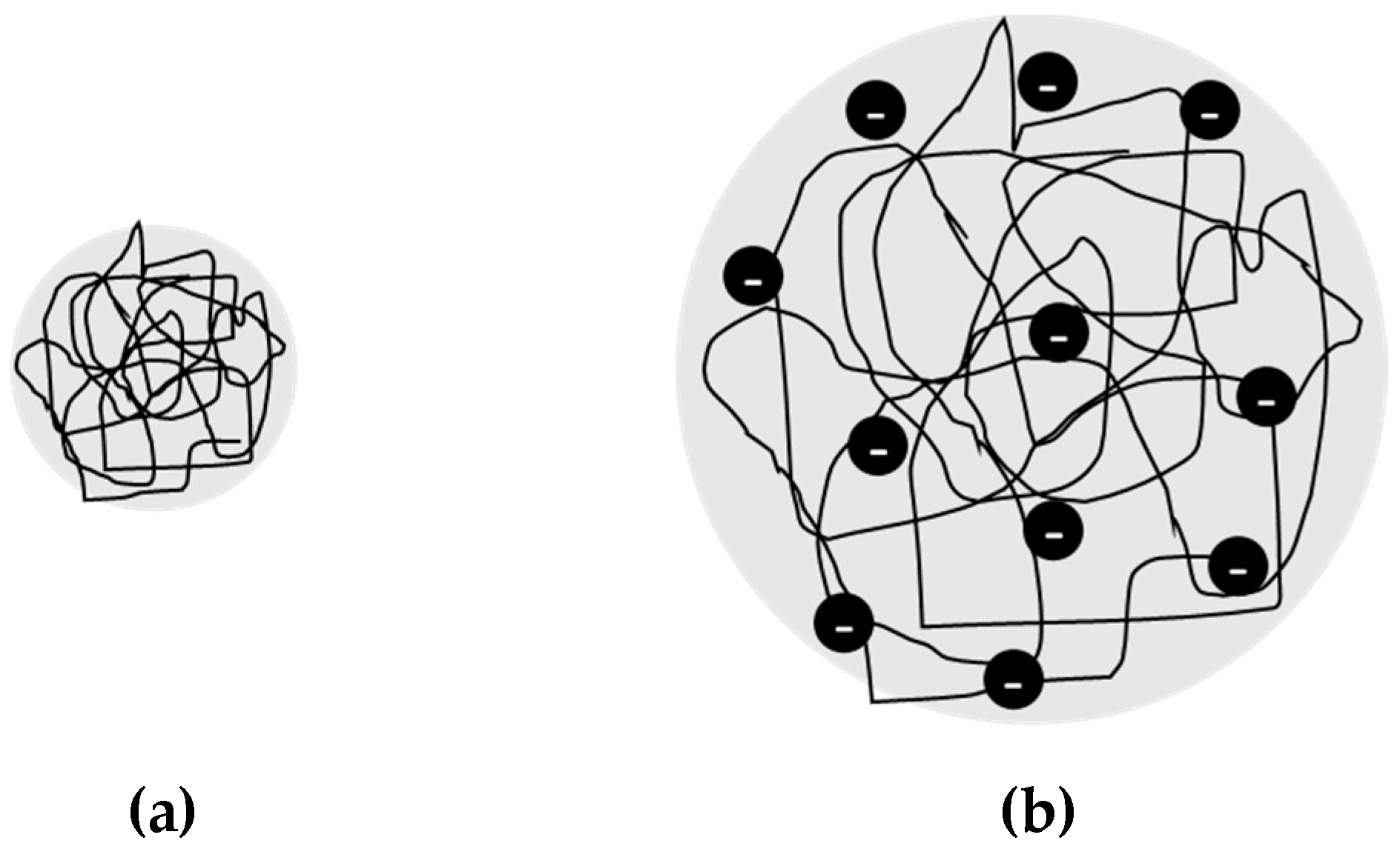
Targeting and evaluating a polymer composition includes several different considerations, from general properties (nonionic polymers vs. polyelectrolytes) to the cumulative composition of a multicomponent polymeric material. One of the primary advantages of nonionic polymers for EOR is their relative insensitivity to high levels of salinity and hardness [51,52]. Since the materials are not dependent on ionic characteristics for viscosity modification, they exhibit consistent viscosities under harsh reservoir conditions. However, in many cases, much larger quantities of the polymer are required to achieve the desired viscosity modification compared to polyelectrolytes. For example, (as per Figure 2), partially hydrolyzed polyacrylamide (HPAM) provides much stronger viscosity modification than nonionic polyacrylamide, as the polymer coils of HPAM expand (increasing the hydrodynamic volume and, subsequently, the intrinsic viscosity) due to charge effects [53].
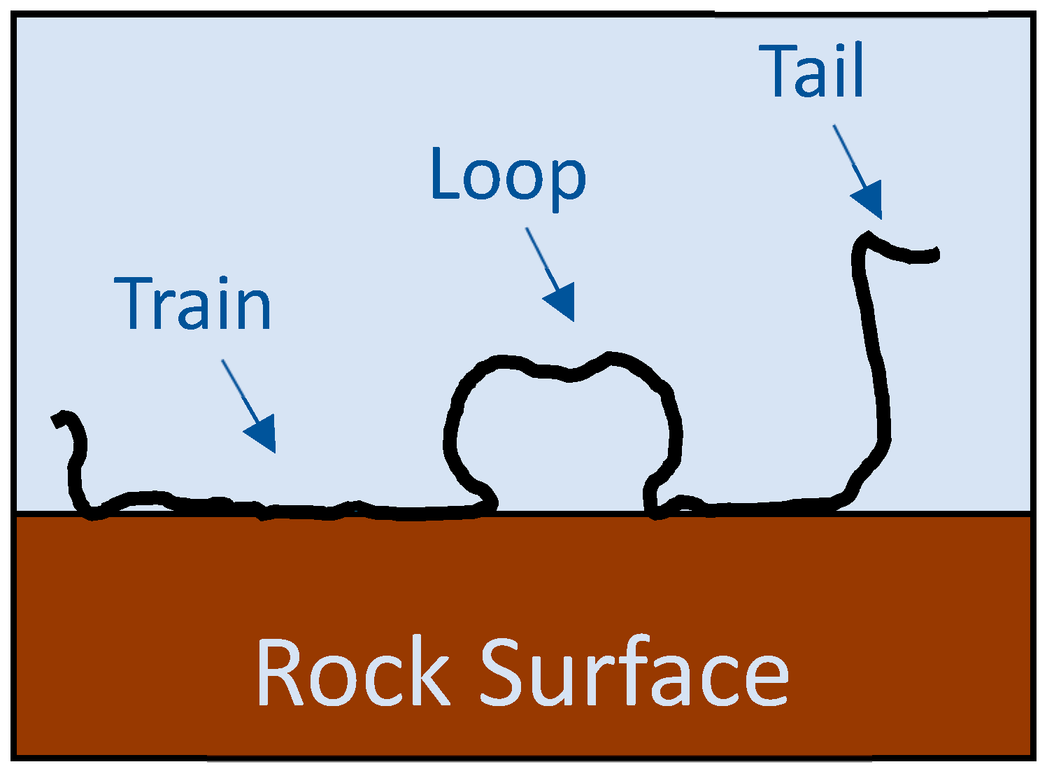
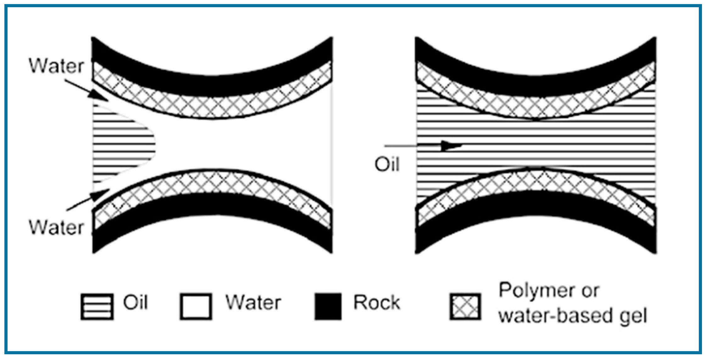
The viscosity modification ability of polyelectrolytes is one of the main motivators for using anionic or cationic polymers in EOR, but other advantages include good water solubility and a desirable impact on effective permeability (recall Equation (2)). Since HPAM is anionic under typical reservoir conditions, the negatively charged polymer backbone will partially adsorb onto rock pore surfaces [54,55]. This ultimately lessens channeling by reducing the pore cross-section (steric effects), creating a “lubrication effect” to promote oil flow and improving water wettability [56]. Therefore, more of the reservoir is exposed to the displacing fluid, and less oil is left behind. However, it is important to carefully consider such charge effects, especially in terms of permeability; if the polymer layer is too thick (or if the average pore size in the reservoir is initially very small), the adsorption (charge) effects could adversely impact the polymer-flooding process, creating pore plugging and causing permeability reduction issues after the polymer-flooding stage is complete.
Generally speaking, anionic polymers are preferable (and more common) than cationic polymers for polymer flooding. Anionic materials like HPAM are relatively inexpensive (especially compared to cationic polymers); they are effective viscosity modifiers, and high molecular weights can be obtained [54]. Cationic polymers tend to be more shear-sensitive, and high molecular weights may be harder to achieve [54]. However, some cationic polymeric materials have been investigated with EOR in mind [57,58,59]. For example, Al-Sharji et al. [57] used cationic polyacrylamide (CPAM; molecular weight = 6×10⁶ g/mol and 10% cationicity) to study disproportionate permeability reduction (that is, decreasing water permeability while keeping the oil permeability as high as possible). Additionally, Zou et al. [58] evaluated the properties of novel anionic and cationic polyacrylamide-based polymers for EOR (including intrinsic viscosity, salt resistance, thermal resistance, and shear resistance). Overall, both materials performed better than standard polyacrylamide, and the cationic polymer (poly(acrylamide/allyl-β-cyclodextrin/dimethyl diallyl ammonium chloride)) had some advantages over the anionic polymer (poly(acrylamide/allyl-β-cyclodextrin/sodium acrylate)). However, one of the main concerns in an oil reservoir would be the potential for pore plugging, as most minerals contain negative charges [53].
Once the desired charge (or lack of charge) is established for a particular polymer-flooding study, one must consider the degree of anionicity or cationicity. Again, employing the widely used HPAM as a benchmark, the degree of hydrolysis (the degree of anionicity) typically ranges from 15% to 35%. The optimal charge density is reservoir-dependent but can be controlled using two different techniques: hydrolysis of polyacrylamide (through co-hydrolysis or post-hydrolysis, see [54,60]) or copolymerization of acrylamide and acrylic acid (sodium acrylate) [26,61,62]. Extensions to other polyacrylamide-based polyelectrolytes would typically involve multicomponent polymerization (see, for example, [26,27,28,53,63]). Although hydrolysis and copolymerization both achieve the desired effect (synthesis of HPAM), copolymerization ensures a more even charge distribution along the polymer backbone [54]. Well-spaced anionic sites are achievable using mild alkaline hydrolysis, whereas strong acid hydrolysis is more likely to produce “blocky” segments of the anionic repeating units [64].
If hydrolysis is the synthesis method of choice, the degree of hydrolysis can be established via potentiometric titration studies (see, for example, [26,60,65,66]). However, if we consider that HPAM and other related derivatives are all essentially multicomponent polymers (either acrylamide/acrylic acid copolymers or something more complex), evaluating the cumulative copolymer composition tends to be the most straightforward (and most enlightening) approach.
Elemental analysis is an analytical technique in which polymer samples are burned at high temperatures, product gases are converted to easily separated (and measurable) components, the gas components are separated with an adsorption column, and components are measured (often with a thermal conductivity detector). If, for example, copolymers of acrylamide and acrylic acid were being evaluated, the measurable elements (to be analyzed) would be carbon, nitrogen, and hydrogen. Since the stoichiometric proportions of the individual elements are known, calculating the molar fraction of each comonomer is relatively straightforward. This approach is more widely used in recent EOR literature [29,61,67].
Another popular analytical technique for composition determination is nuclear magnetic resonance (NMR; either 1H-NMR or 13C-NMR, depending on the system). This technique can be used to distinguish between functional groups that are specific to each comonomer, and relative proportions can be calculated (see, for example, representative studies, including [26,33,68]). It can be complementary to another analysis technique (like elemental analysis, for example) and has generally shown good agreement [26,69]. However, using NMR for EOR polymers has several limitations, including difficult sample preparation and overlapping (indistinguishable) peaks. For example, Riahinezhad et al. [70] reported difficulty during sample preparation for acrylamide/acrylic acid copolymer analysis. Apparently, the necessarily high solution concentration led to extremely viscous samples, which made sample preparation (especially insertion or transfer of solutions into NMR tubes) rather tedious and impractically time-consuming, if at all possible. Additionally, in some cases (depending on the comonomers being evaluated and the copolymer composition), characteristic peaks may be indistinguishable. For example, Preusser et al. [68] found that 1H-NMR peaks for acrylamide and acrylic acid overlapped at intermediate degrees of ionization.
Ultimately, characterizing the composition of candidate materials for polymer flooding is an important aspect of the screening process. Not only do researchers need to be aware of charge effects (in the polyelectrolyte case), but they should also consider the fractions of unique comonomers in a multicomponent material. For example, a high acrylamide fraction is often desirable in copolymers for polymer flooding; in contrast, too much acrylic acid can lead to brine sensitivity [71]. Other comonomers (like 2-acrylamido-2-methylpropane sulfonic acid, acryloyl hydrazide, or n-vinyl pyrrolidone) may provide additional benefits, like improved mechanical and/or thermal stability [26,27,28,31,33]. There are countless possibilities when multicomponent polymerizations are considered, but the target properties must be well-understood. The cumulative composition of a multicomponent polymer is best controlled when reactivity ratios are known [72,73]. Armed with sufficient information about polymerization kinetics and the desired polymer properties, prepolymerization recipes can be selected accordingly [69].

3.1.2. Polymer Microstructure

The “most desirable” polymer microstructure depends largely on the polymer composition and application (reservoir) conditions, which means that each investigation will be targeting a unique polymer microstructure. For example, the microstructure of polyelectrolytes will primarily impact the charge density (and subsequent brine compatibility) [20,61], whereas the microstructure of hydrophobically modified water-soluble polymers will affect the hydrophobic associations within and between coiled polymer chains [19]. Therefore, a “polymer microstructure” relates to several molecular properties that can influence EOR.
A consideration of polymer microstructures for enhanced oil recovery may include the molecular architecture, the statistical distribution of comonomer units along a linear backbone, or both. The rheology of polymer solutions can change drastically, depending on whether linear or branched polyacrylamides are employed [24,25]. In fact, Zhu et al. [25] reported that using nonlinear architectures (comb-shaped, branched, and star-shaped polymers) improved the salt tolerance in terms of viscosity modification and long-term stability. As described earlier (in Figure 2), linear polymer molecules can be significantly affected by charge effects in solutions; high salinity environments can cause polymer coils to shrink, thus reducing the hydrodynamic volume and lowering the viscosity modification ability. Using unique (dense) polymer architectures ensures that viscosity modification is due to the microstructure (and is not reliant on polymer coiling in solutions), which means that branched molecules can overcome the viscosity reduction limitations associated with linear EOR polymers.
Polymers with unique architectures are often characterized in terms of surface morphology (through scanning electron microscopy (SEM), transmission electron microscopy (TEM), etc.) [29,34,35,37,38,74]. The direct imaging of polymer samples in aqueous solutions can be achieved using low temperature techniques, such as cryo-TEM [74,75] or environmental scanning electron microscopy (performed at −3.5 °C in the study by Zhong et al. [29]). The idea here is to evaluate network formations within and between polymer chains, and imaging can be especially useful for stimuli-responsive materials [74]. However, it is somewhat limited by the fact that it is a fairly qualitative (and therefore, somewhat subjective) technique.
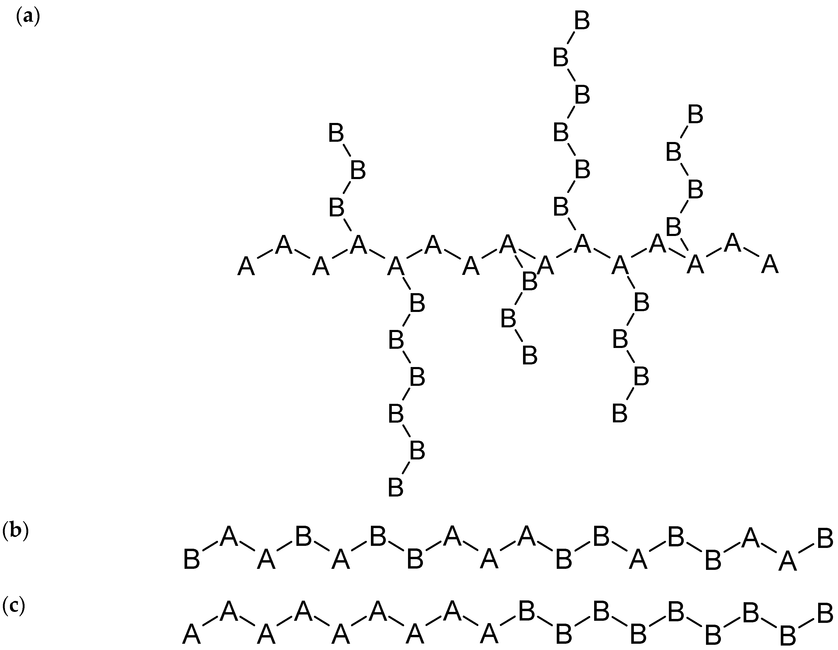
Of course, polymer architecture is relevant for both homopolymers and multicomponent polymers (consider graft copolymers, for example [76]; see Figure 3a). However, for multicomponent polymers, the statistical distribution of comonomer units along the backbone must also be considered. The structure of the copolymer (random, block, etc.) can significantly affect the conformation of polymer chains in solutions, which in turn affects solution viscosity and EOR sweep efficiency [77]. Therefore, the distribution of the comonomers along the polymer backbone is an important material property in polymer flooding applications; several copolymer structures are shown in Figure 3 and described in what follows.
Random copolymers (Figure 3b) tend to be the most widely employed microstructures in enhanced oil recovery [26,32,33,61,63,76,77,78]. However, there can be a significant variety of structures among random copolymers; estimating or measuring the triad fractions and/or sequence length distribution can provide additional information about the material. The sequence length distribution can be predicted using probability functions, as long as the reactivity ratios and the composition of the polymerizing mixture are known [63,76,79]. These calculations rely on theory, and previous research has shown promising agreement between experimental results from 13C-NMR and the predicted triad fractions [80,81,82,83]. The evaluation of the sequence length distribution of hydrolyzed polyacrylamide has been demonstrated by Halverson et al. [64].
Block copolymers (Figure 3c) and microblock copolymers have been employed in several EOR studies (see, for example, [29,84,85,86]). Hydrophobically modified water-soluble polymers (containing both hydrophobic and hydrophilic moieties) are often synthesized to promote microblock behavior (that is, longer sections of one comonomer alternating with longer sections of the other). Studies have shown that the microblock length impacts the rheological properties of polymer solutions; longer hydrophobic blocks enhance the viscosity modification [87]. Alternatively, when there are two distinct blocks (diblock copolymer) with drastically different properties, the polymer essentially acts as a surfactant, simultaneously increasing the flood water viscosity and reducing the interfacial tension within the oil reservoir [86]. A common technique for identifying hydrophobic microblocks is to employ fluorescence; when the concentration of a pyrene label (on the hydrophobic comonomer) is large enough to form an excimer, researchers can confirm the presence of hydrophobic microblocks (microdomains) in their polymers [29,77,85].
In looking specifically at the EOR literature, though, there is very little consistency in the experimental evaluation of copolymer microstructures. Often, the copolymer structure is assumed based on the synthesis technique (i.e., random comonomer distribution from free-radical polymerization, microblock structure from micellar polymerization, etc.) [26,77] or it is not mentioned at all [11,30,32,34,35,37,38,74]. Making assumptions based on synthesis technique is a good starting point (and is better than ignoring the microstructure altogether!), but such assumptions do not necessarily provide information about the true microstructure of the multicomponent polymeric materials; quantitative properties like sequence length distribution and triad fractions are rarely mentioned.
Consider the following: when water-soluble polyelectrolytes are used for polymer flooding, an even distribution of charges is preferable [20,61]. However, this “even distribution” does not necessarily imply alternating behavior. In a terpolymer case like 2-acrylamido-2-methylpropane sulfonic acid, acrylamide, and acrylic acid, two of the three comonomers are contributing to the charge density. Therefore, it becomes necessary to consider the charge alternation, not a simple monomer alternation. In a recent study by Scott et al. [63], the random distribution of charges was achieved through the ternary reactivity ratio estimation, triad fraction prediction, and optimization of desirable and undesirable triad fractions. Thus, customization potential is possible when the kinetic details about a polymerization process are well-understood; this knowledge should be pursued in future analyses and the determination of desirable property indicators (structure-property relationships) of EOR polymers.

3.1.3. Molecular Weight Averages

High molecular weight polymers increase the solution viscosity and the permeability reduction factor (that is, the ability for EOR polymers to adsorb onto the porous walls, reducing channeling effects and increasing sweep efficiency) [13]. The increased viscosity and permeability reduction factor both increase the oil recovery factor (compared to the same amount of a lower molecular weight polymer), which means that a high molecular weight polymer solution requires less polymeric material to achieve a designated recovery factor. The advantage of using less polymeric materials in the EOR process is evident, both in terms of environmental and economic implications.
If the molecular weights are too high, there will be additional complications associated with the EOR application. One of the major issues is the potential degradation of the polymer, as high molecular weight chains tend to be more shear-sensitive (especially in typical EOR conditions) [27]; this will be discussed further in Section 3.2.1. Another concern is that the viscosity of the polymer-flooding solution may end up being too high. This could lead to problems with reduced injectivity (where injectivity is the ratio between injection rate and pressure drop) and slower fluid throughput in the reservoir (largely due to plugging) [88]. In terms of biopolymers for EOR, the material with the highest achievable molecular weight (2 × 10⁶ g/mol – 50 × 106 g/mol, as reported by [19]) is xanthan gum; this may be one of the reasons why it is a popular biopolymer for polymer flooding. Similarly, in terms of synthetic materials for EOR, reported molecular weight averages range from 104 g/mol [24] to 107 g/mol [25,27]. Most researchers studying polymers for EOR agree that a target molecular weight on the order of 106 g/mol is appropriate [19,27,61]. Therefore, molecular weight control is important during the design and synthesis of EOR polymers.
Gel permeation chromatography (GPC), which is commonly used for the molecular weight analysis of polymer samples, uses columns of small diameters filled with porous gel particles (column packing) to separate polymer molecules by size. The larger polymer molecules (those with large hydrodynamic volumes) are not able to enter the pores of the column packing, which means that they flow directly through the GPC column. In contrast, smaller molecules are able to enter the porous gel particles, which ultimately delays their passage through the GPC column. As a result, the differently sized polymer molecules elute at different times (larger molecules first and smallest molecules last), and the full sample distribution is measured using appropriate detectors. Most GPC units have some combination of detectors to measure polymer concentrations and some molecular weight averages and may typically include a differential refractometer, a UV detector, a viscometer detector, and/or a light-scattering detector (low-angle light scattering, right-angle light scattering, multi-angle light scattering, etc.). Calibration using well-characterized polymer samples is an essential part of accurate molecular weight determination.
However, for both xanthan gum and polyacrylamide-based materials, molecular weight determination is notoriously difficult. Xanthan gum, in particular, has very high molecular weights, a “stiff” polymer backbone, and often forms aggregates [89,90]. As a result, the hydrodynamic volume is particularly large, and most gel permeation chromatography (GPC) columns cannot adequately separate the sample for accurate characterization. Additionally, the xanthan gum sample would be exposed to a high shear rate, as it passes through the GPC column; shear degradation may occur during analysis, resulting in measurements that exhibit a bias towards lower molecular weights (“low bias”) [89]. Therefore, classical light scattering is the most widely used method for measuring the weight-average molecular weight of xanthan gum, but other molecular weight averages (number-average molecular weight, for example) often remain a mystery [90].
Similar complications exist for the analysis of synthetic polymers, and polyelectrolytes, in particular. The viscous nature of polymer solutions (along with very high molecular weight averages, charge effects, and potential microgel formation) can make GPC analysis extremely challenging. During a recent investigation involving the terpolymer of 2-acrylamido-2-methylpropane sulfonic acid, acrylamide, and acrylic acid, Scott and Penlidis [69] found that careful sample preparation and a critical analysis of results allowed for a more accurate determination of molecular weight averages. To minimize the charge interactions between the column packing and the polymer samples, a buffer solution of pH 7 was used as the mobile phase. The buffer was prepared using sodium nitrate (0.2 M) and sodium phosphate (monobasic and dibasic, 0.1 M) in Millipore quality water. The synthesized polymers were dissolved in the mobile phase (pH 7 buffer) to obtain concentrations of ~1 mg/mL. The solution preparation step required fine grinding prior to dissolving polymers in the buffer and allowing the solutions to sit under ambient conditions (with occasional manual mixing) until the polymer was dissolved. This sometimes took several days, since the material did not dissolve easily. Prior to injection, polymer solutions were filtered through a 0.2-μm filter. Ultimately, the study showed the importance of using GPC-measured concentrations when analyzing multicomponent polyelectrolytes, rather than relying solely on the concentrations determined during sample preparation. With high acrylamide content and high molecular weights, the high viscosity may affect polymer dissolution and limit subsequent filtration. As a result, the measured molecular weight averages may be underestimated. Some of the larger polymer chains (higher molecular weights) may be filtered out during sample preparation, thus creating a ”low bias” in the measured molecular weight averages.
An alternative technique for molecular weight determination is field flow fractionation (FFF), which is still a fairly new characterization technique and is especially useful for large molecules like polymer samples and microgels [91]. One of the main differences compared to GPC is that there is no stationary phase (that is, no column packing); molecules are separated using laminar flow behavior, concentration effects, and analyte retention. This makes it possible in principle to separate molecules by size and composition simultaneously; Messaud et al. [91] suggest that the technique could be used to evaluate polymers with molecular weights as high as 109 g/mol, and the polymer chains would undergo minimal shear degradation during analysis. In a recent study, Choi et al. [62] used FFF to evaluate ultra-high molecular weight polymers for EOR. In their work, they were able to evaluate an ultra-high molecular weight HPAM sample (absolute-weight average molecular weight reported as 7.330 × 10⁶ Da) using a solution of sodium chloride (NaCl; 0.1 M) and sodium azide (NaN3; 0.2 g/L) as the effluent [62]. More details about FFF (and variations on the technique) have been provided in a detailed review by Messaud et al. [91].
Finally, molecular weights can also be evaluated (rather simply) through viscometry [92]; the viscosity-average molecular weight can be correlated with intrinsic viscosity, as per the Mark-Houwink equation (Equation (3)).
[ η ] = K M α
[η] above is the intrinsic viscosity (that is, a polymer molecule’s contribution to the viscosity of the solution, assuming no interactions (noninteraction can be “forced” by evaluating polymer solutions at very low concentrations)). M represents the molar mass of the polymer, and K and α are empirical constants (obtained from experimental data). The most experimentally simple approach is to use an Ubbelohde viscometer for viscosity measurements (and subsequent molecular weight determination). This approach has been employed in several EOR studies, including [11,25,29,93]. It can be especially useful for ultra-high molecular weight polymers; Zhu et al. [25] reported molecular weights up to 25 × 106 g/mol. The approach is admittedly simple and, hence, popular for relative (quality control) comparisons, if one is careful and consistent with the experimental steps involved. However, the approach may also introduce errors of uncertain magnitude, especially due to the propagation of error from successive dilution steps.

3.2. Polymer Degradation

These fundamental polymer properties provide us with an excellent starting point for EOR materials, but it is equally necessary to evaluate application-specific requirements. Polymer degradation, for example, is an extremely important consideration in EOR, as the polymer-containing flood water will likely be subjected to harsh environments. That said, it is not always easy to evaluate (much less quantify) a material’s resistance to degradation; high shear rates, high temperatures, contaminants, and long-term stability (aging) must all be considered. Quantitative analysis is especially important at present, as researchers search for new materials that can be used in high-temperature and high-salinity reservoirs [4,17]. There must be benchmarks and “best practices” in place so that significant improvements in polymer stability can be conclusively validated. Thus, in what follows, various degradation concerns are briefly explained, and relevant analysis techniques are described.

3.2.1. Shear Degradation

One of the biggest concerns, especially for acrylamide-based polymers, is the potential shear degradation of the material. During polymer flooding, the polymer solution is typically exposed to high flow rates (and therefore, high shear stresses) and sudden changes in pressure, which are known to cause backbone degradation [20,54]. This ultimately reduces the molecular weight of the polymer, which in turn reduces the viscosity (and efficiency) of the polymer solution. As described previously (Section 3.1.3), polymers with high molecular weights provide several benefits for EOR (including viscosity modification). However, when molecular weights are too high (and the polymer composition/structure does not provide additional shear resistance), the polymer chains can be extremely shear sensitive.
Thus, in evaluating potential polymeric materials for EOR applications, an important consideration is the resistance to shear degradation. Many papers claim to have developed new materials with improved shear stability, but their claims are often backed by theoretical expectations rather than experimental data [28,29,94]. Therefore, the purpose of this section is to summarize studies in which shear degradation considerations were not only described but also evaluated experimentally. Hopefully, this will motivate more researchers to pursue concrete evidence of improved shear stability as they develop and characterize new polymeric materials for EOR.
Zaitoun et al. [27] developed an experimental technique for quantifying the shear degradation of polymer solutions. In this technique, the polymer solutions were prepared with varying concentrations, such that all solutions tested had the same approximate viscosity (~20 mPa∙s). Concentrations ranged from 850 ppm to 4800 ppm of polymeric material in brine (2% potassium chloride (KCl) and 400 ppm sodium azide (NaN3) in water). For each test, the polymer solution being evaluated was pumped at a constant flow rate through a stainless-steel capillary tube (ID = 125 μm; L = 5 cm). After 50 mL of polymer solution was pumped through the system, the effluent was collected for viscosity measurements. Finally, the degree of degradation was calculated by comparing the “degraded sample” viscosity (measured using a Couette viscometer at 30 °C) to the initial viscosity (of the nondegraded polymer solution).
This process was repeated several times for each polymer, but a different flow rate was used for each subsequent run. Eventually, this provided information about how the degree of degradation varied with shear rate (which is related to the polymer solution flow rate and the capillary tube geometry, as shown in Equation (4)).
γ = 4 q π r 3
In Equation (4), γ is the shear rate, q is the volumetric flow rate, and r is the capillary radius.
Overall, this technique seems rather time-consuming and experiment-heavy, but it provides a very good understanding of the shear degradation of each polymeric material studied. As additional confirmation that this approach gives trustworthy results, Zaitoun et al. [27] compared the shear degradation of six unique acrylamide-based materials to a (shear-stable) xanthan gum sample. The results were as expected; all acrylamide-based materials were shear-sensitive and exhibited increasing degrees of degradation with increasing shear rates. In contrast, the xanthan gum sample underwent minimal degradation (only 3.8% degradation at a shear rate of 870,000 s−1 compared to >50% degradation for acrylamide-based materials under the same conditions). Thus, if shear degradation is an important consideration for a particular material or reservoir geometry, this approach by Zaitoun et al. [27] can provide more insight about the shear resistance of a given polymer.
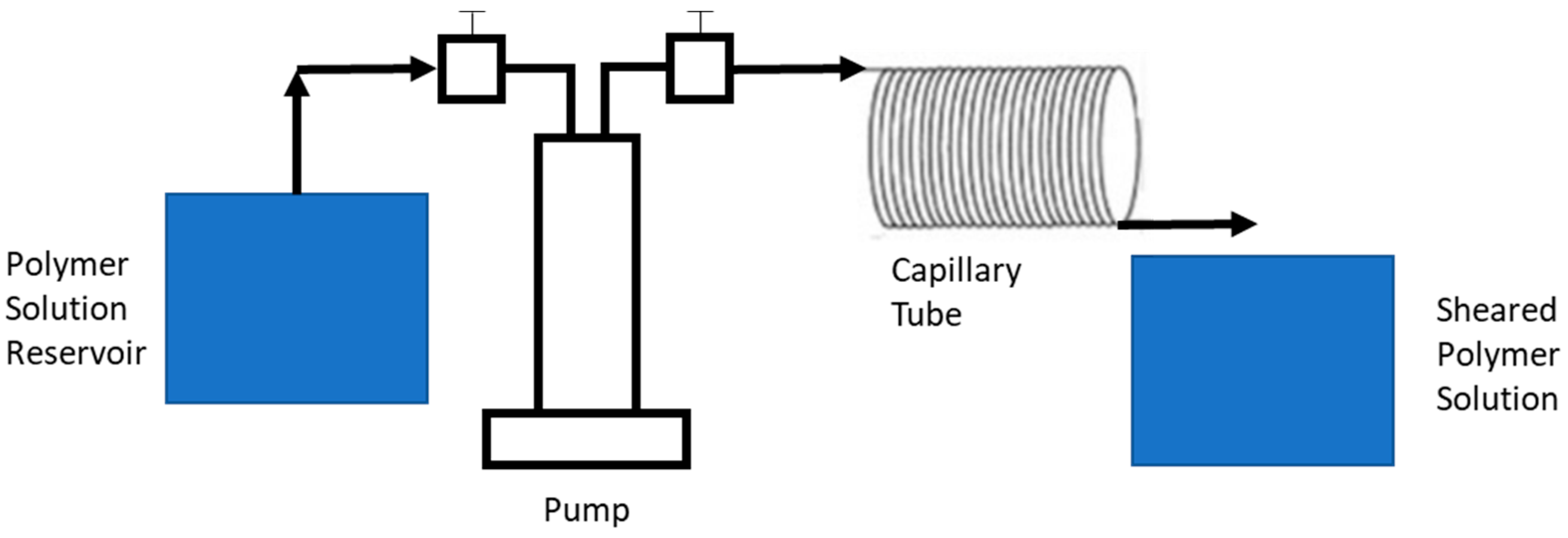
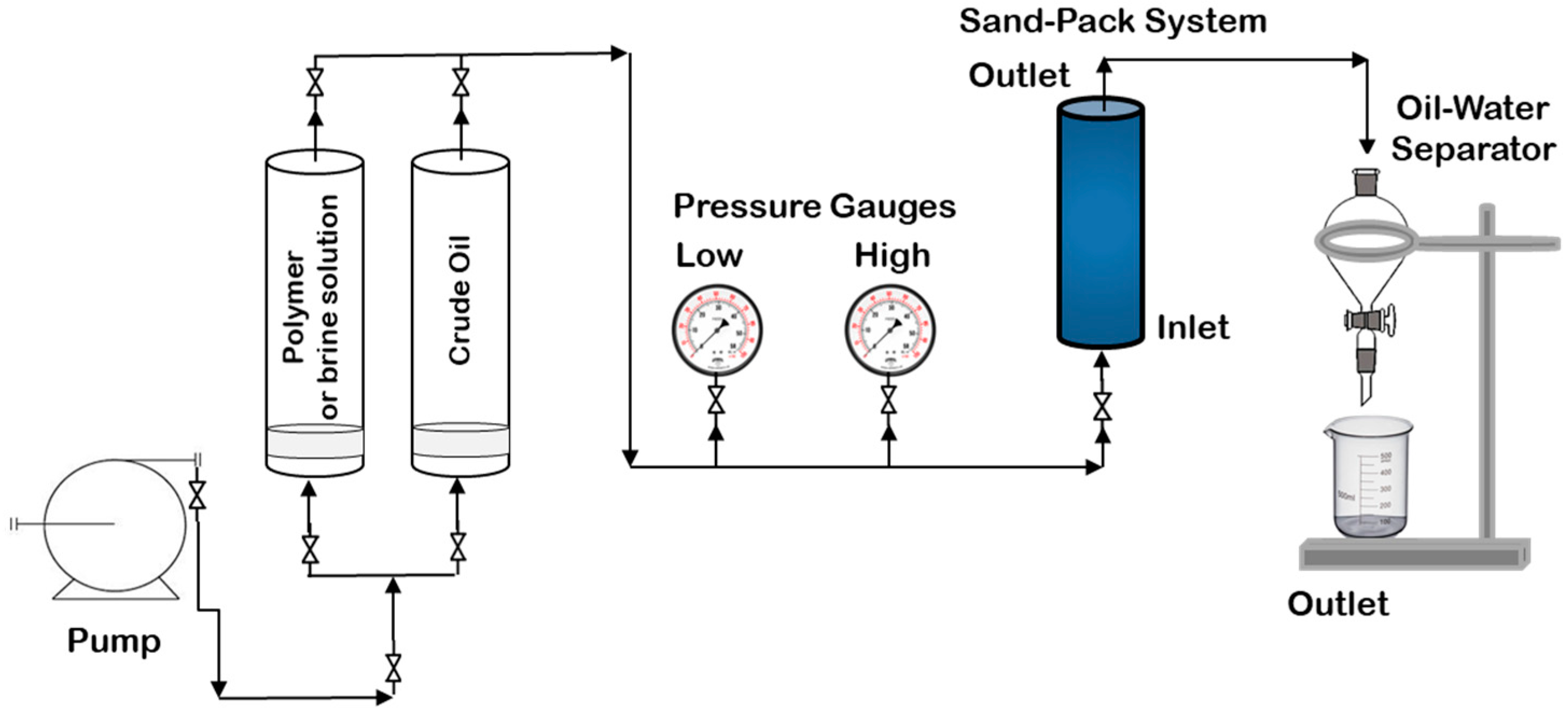
A later study by Wei et al. [12] evaluated the shear resistance of three polymers that could be used in EOR: HPAM, a hydrophobically modified acrylamide-based polymer, and xanthan gum. For their experimental work, polymer solutions (with concentrations ranging from 0.4 wt %–1.0 wt %) were prepared in synthetic brine (1.72 wt % NaCl, 0.09 wt % MgCl2, 0.32 wt % CaCl2, and 0.009 wt % Na2SO4). Once the solutions were prepared, two different techniques were used to evaluate the mechanical degradation of each material. One approach (the “capillary tube” method) used an experimental set-up that was similar to that described by Zaitoun et al. [27]. The main difference in the experimental set-up was the capillary tube geometry (ID = 1 mm; L = 3 m), but otherwise, the same general procedure was followed; see also, Figure 4.
Wei et al. [12] calculated the mechanical degradation of each polymer sample (viscosity loss) from viscosity measurements at a shear rate of 6 s−1, which is similar to the “degree of degradation” calculation reported by Zaitoun et al. [27].
V i s c o s i t y   L o s s ( % ) = μ 0 μ μ 0 × 100
μ0 is the viscosity of a “pristine” (nondegraded) polymer solution (shear rate = 6 s−1) and μ the viscosity of the degraded polymer solution (again, shear rate = 6 s−1).
The second approach that Wei et al. [12] used to evaluate shear degradation was through direct parallel plate rheometry (D = 60 mm; 1 mm gap; 25 °C). The shearing conditions (shear rate and time) were selected so that the polymers would be exposed to similar conditions using both the parallel plate method and the capillary tube method. Comparison of results showed that the capillary tube method resulted in much larger viscosity losses, especially for HPAM. Wei et al. [12] suggest that the elongational deformation that occurred during the capillary tube study resulted in additional viscosity loss. That being said, the viscosity loss was likely a combination of (irreversible) mechanical degradation and other (reversible) effects. That is, disentanglement and/or alignment of polymer molecules would have affected the hydrodynamic volume of the molecules and their subsequent viscosity modification ability. Wei et al. [12] confirmed this via a reformability study, in which some viscosity recovery was measured throughout four weeks of relaxation time.
These techniques were further extended to evaluate the effect of brine salinity on mechanical degradation [12]; the same experimental techniques described above can be employed with a more concentrated synthetic brine. The impacts of salinity and hardness will be discussed further in Section 3.3, but combining mechanical effects with salinity effects brings the analysis one step closer to “real” reservoir conditions.
While Zaitoun et al. [27] and Wei et al. [12] demonstrate a detailed experimental evaluation of shear resistance, other researchers use different (often simpler) methods to evaluate their candidate polymers for EOR. For example, Sabhapondit et al. [26] compared the shear resistance of four acrylamide-based copolymers (0.8% solution of polymers in water, evaluated at 25 °C using a rotational rheometer; shear rate = 1 s−1 to 1312 s−1). Their claim that some polymers were more shear-resistant than others was informed by parameter estimates obtained by using experimental data and the power law model (Equation (6)).
η = K γ n 1
η represents the apparent viscosity, K is the flow consistency index, γ is the shear rate, and n is the power law index. Since the value of n (estimated by linearizing the power law model) is related to the non-Newtonian flow behavior of the polymer solution, Sabhapondit et al. [26] used their estimates of n to quantify shear sensitivity for each polymer solution. Most polymeric solutions for EOR are shear-thinning (pseudoplastic) fluids; therefore, 0 < n < 1. However, values that are closer to zero are more shear-thinning (that is, there is a larger viscosity decrease as shear stress increases). Therefore, since Sabhapondit et al. [26] used n values as the main indicator for shear stability, lower n values (~0.23–0.28) were labeled shear-sensitive, while higher n values (~0.40–0.44) were considered more shear-resistant. This type of analysis provides a good starting point for the consideration of shear resistance, but it does not look at mechanical degradation in the same way as the studies mentioned previously. Any viscosity decreases described here may be due to changes in coil conformation within the solution, backbone degradation, or some combination thereof. So, it is difficult to establish whether or not the materials are truly shear-resistant.
However, the second experimental technique reported by Sabhapondit et al. [26] can help establish whether or not the observed viscosity losses are permanent. Polymer solutions (0.02% polymer sample in water) were exposed to a constant shear rate (36.72 s−1) for up to 12 h at 30 °C, and the apparent viscosity was measured throughout. Then, the shear was removed, and the polymer solutions were left to recover (again, for 12 h). While some of the samples partially regained viscosity, none were able to return to the initially measured (pre-shear) viscosities [26]. This result suggests that some polymer formulations degrade more than others, but that high shear rates permanently impact the viscosity (and subsequent performance) of all acrylamide-based copolymers.
Finally, it is important to mention that many studies concerning shear degradation for EOR polymers contain industrial data (see, for example, [20,95,96]). This shows the immediate importance and relevance of this research, but the authors may not be able to share all of the formulation or characterization details. Once such example is the work published by Thomas et al. [20]. The publication describes the impact of shear degradation as a function of polymer molecular weights and reports that higher molecular weight polymers exhibit more viscosity loss. However, general descriptions (for example, “an acrylamide-based copolymer with medium molecular weight”) must be employed to protect the intellectual property of the company. Although characterization details were limited in the study by Thomas et al. [20], the experimental process was likely similar to those described by Zaitoun et al. [27] and Wei et al. [12]; Thomas et al. [20] reported that their experimental set-up included a pipe with ID = 0.875 mm and L = 200 mm.
Other industry-based publications report results obtained on a much larger scale [95,96]. In the work by Jouenne et al. [95], the degradation of HPAM during turbulent flow in pipelines was considered. Viscosity measurements of numerous polymer samples (aqueous solution concentrations ranging from 300 ppm and 2000 ppm) collected at predetermined checkpoints along the pipeline provided a good understanding of viscosity losses throughout the transport process. Similar tests were done under different flow conditions (varying pipe diameters and/or solution velocities), which led to specific recommendations for polymer solution transport. Ultimately, both the polymer products and the polymer-flooding process must be designed in such a way that shear degradation is limited.

3.2.2. Thermal Degradation

Next, thermal degradation studies are considered. Many researchers (including [20,26,29,31,35,37,62]) are working towards more thermally stable polymers for EOR, especially since polymer flooding is currently limited to reservoirs with moderate temperatures. Although some researchers have reported that polymer flooding can be used in reservoirs up to 100 °C [97], Sheng et al. [17] found that the median temperature for polymer-flooding projects was only 46.1 °C. The general aversion to high-temperature conditions is likely due to two major temperature-related limitations for EOR polymers: the potential for degradation of the polymer backbone and the potential for hydrolysis [98,99]. The issues associated with backbone degradation (and, ultimately, a reduction in polymer molecular weights and viscosity modification ability) have already been described in the previous section, so a brief discussion on hydrolysis is in order. Polyacrylamide hydrolysis can occur at temperatures as low as 60 °C [10,98]. However, other factors (like oxygen contamination or solution hardness) can further increase the degree of hydrolysis at a given temperature (this will be discussed further in Section 3.2.3). Hydrolysis essentially changes the chemical composition of the polymeric material (since amide groups are being converted to carboxylic acid groups), which affects the polyelectrolyte behavior of the polymer chains and can lead to significant (problematic) precipitation when divalent cations are present in the polymer solution [20,99].
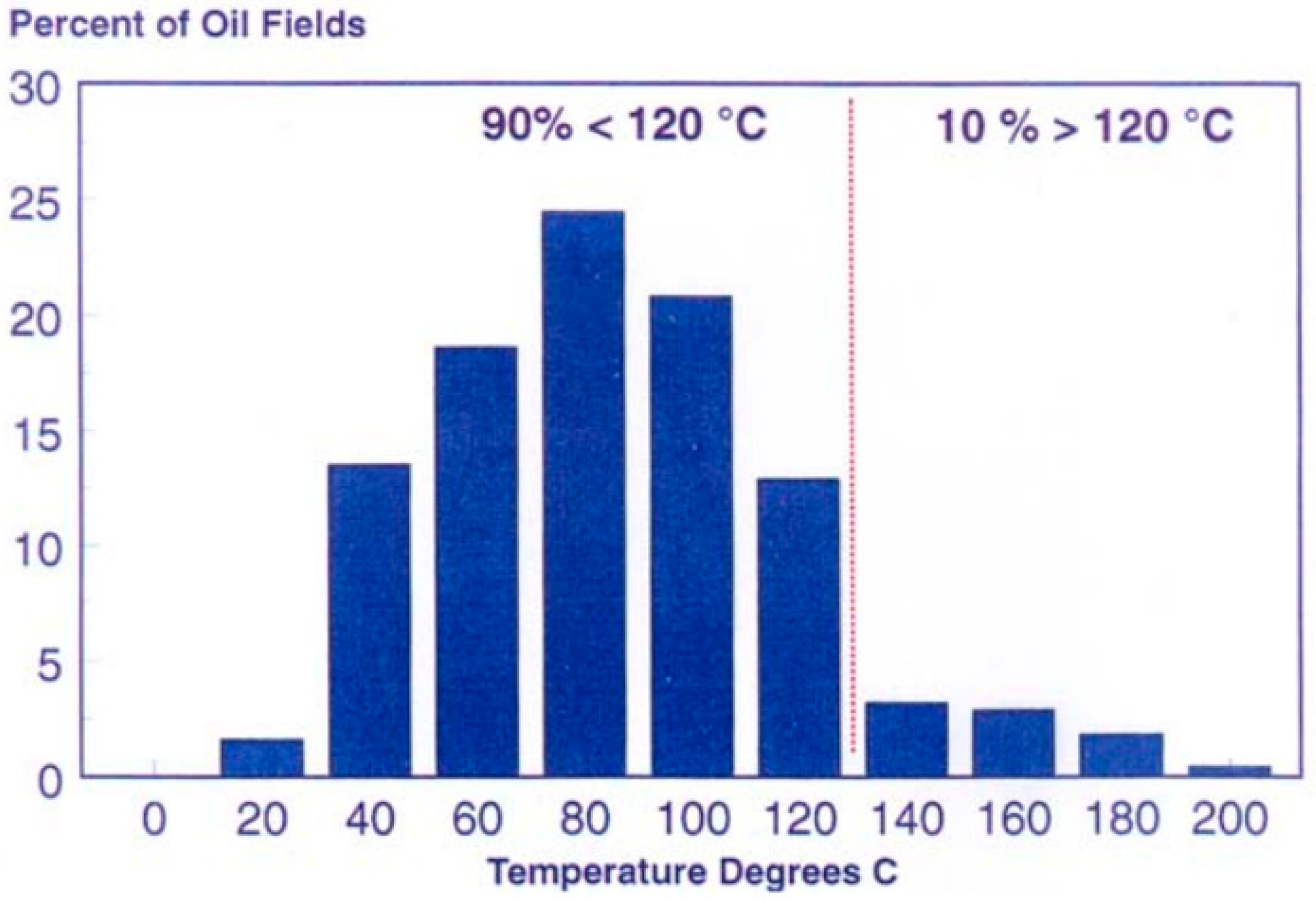
As shown in Figure 5, Bjorkum and Nadeau [100] reported that the majority of oil fields are below 120 °C, but polymeric materials for EOR should be stable until at least 200 °C. Therefore, there is a significant potential to further improve EOR polymers for high(er) temperature reservoirs [4,17].
Understanding the importance of using thermally stable materials is only part of the process. It is equally important to establish how best to evaluate a given polymeric material’s resistance to thermal degradation. Throughout the literature, researchers have used a variety of techniques to prove that their materials would perform well at high reservoir temperatures. Some of these techniques are now described and briefly evaluated.
Thermal degradation studies can be divided into two broad categories: short-term temperature effects and long-term temperature effects. Short-term studies may evaluate the effect of temperature increases on solution viscosity [37,51,62,101] or the decomposition of polymeric materials at high temperatures using thermal gravimetric analysis (TGA) [26,29,35,37,51,69]. Considering temperature effects on solution viscosity can be useful; it is important to ensure that the desired viscosity modification for EOR is still achievable at higher temperatures. However, it may be ill-advised to claim that materials are thermally stable when the only evidence is a high temperature viscosity measurement. Choi et al. [62] claimed that their ultra-high molecular weight HPAM would be suitable for EOR over a wide range of temperatures, but their only experimental evidence was a comparison of viscosity measurements at 25 °C and 70 °C. While the general viscosity trends at 70 °C were suitable, the overall solution viscosity was lower than it was at 25 °C. Thus, one could argue that the higher temperature reduced the viscosity modification ability of the HPAM, and this particular material may not be suitable at all beyond 70 °C. While viscosity measurements at higher temperatures do provide researchers with some insight about the system, more experimental work may be required before drawing conclusions about the thermal stability of the polymer in question. A better example is the work published by Liang et al. [101], which compared the EOR behavior of biopolymers (polysaccharides) to synthetic polymers (HPAM) in high-temperature and high-salinity environments. Liang et al. [101] prepared aqueous solutions of four EOR polymers and chose concentrations that would ensure consistent initial viscosities for all solutions. That is, all four polymer solutions had the same initial viscosity at 25 °C and shear rate = 100 s−1. Apparent viscosity was then measured as a function of temperature using a rotational rheometer equipped with temperature-ramping capabilities (from 25 °C to 150 °C at 2 °C/min). “Thermo-thinning” behavior was reported for all four materials but to varying degrees. While HPAM and xanthan gum solution viscosities decreased significantly (with increasing temperatures), the viscosities of the other polysaccharide solutions (diutan gum and scleroglucan) were not as affected by temperature [101]. This is somewhat as expected, which provides additional confirmation of the validity of the experimental methodology.
An alternative method for evaluating resistance to thermal degradation is through thermal gravimetric analysis (TGA); this provides additional information about the material properties of candidate polymers for EOR. TGA typically involves the slow heating of powdered polymer samples, and the sample mass lost (due to polymer degradation) is measured as a function of temperature. This type of analysis would primarily provide information about backbone degradation, as hydrolysis would not cause significant changes in the sample mass (consider the molecular mass of acrylamide (71.08 g/mol) vs. acrylic acid (72.06 g/mol)).
Most researchers using TGA to evaluate the thermal degradation of EOR polymers follow the same general procedure [26,29,35,37,69]. Typically, a small mass of a given polymer sample is heated under a N2 atmosphere. The main variation between studies is related to the temperature range and the heating rate. Sabhapondit et al. [26], for example, initially held their samples at 150 °C for 5 min (to allow for the complete removal of absorbed moisture from the sample), then heated their samples at a rate of 8 °C/min up to 600 °C. Some studies look at higher temperatures (like the 800 °C maximum reported by Wu et al. [37]), whereas others may use faster temperature ramps (like El Hoshoudy et al. [35], who reported a temperature ramping of 20 °C/min). Slower temperature-ramping speeds can make the thermal transition points clearer, but the overall conclusions would not be much affected by these experimental differences.
Most reports conclude that materials are “thermally stable” if the polymer sample retains most of its mass at the temperature of interest (typically, up to 200 °C). For example, El Hoshoudy et al. [35] evaluated their EOR polymer up to 600 °C but focused on the range of 90 °C to 150 °C (which is the approximate temperature of an oil reservoir). They concluded that their novel copolymer retained an average of 95% of its original mass over this temperature range and that, as such, their material would be thermally stable in high-temperature reservoirs. Alternatively, TGA results may be used to demonstrate the relative improvement of one candidate polymer compared to another [29,37,69]. Zhong et al. [29], for example, compared the initial decomposition temperature of their newly synthesized terpolymer to the initial decomposition temperature of a polyacrylamide homopolymer. The fact that the terpolymer degradation occurred 28 °C above the degradation temperature of the homopolymer proved the improved thermal stability of their newly synthesized EOR polymer.
Regardless of the conclusions drawn from the TGA results, it is important to recognize that the experimental technique is primarily evaluating the temperature effects on the polymer backbone. Aside from some initial water loss, any large reductions in sample mass would result from the loss of polymer side chains and/or thermal degradation of the polymer backbone [37]. The thermal hydrolysis of acrylamide units along a polymer backbone would not easily be evaluated using TGA. Therefore, researchers should use caution when drawing conclusions about thermal stability from TGA results; even when polymers show minimal mass losses during TGA, they may still be affected by thermal hydrolysis. Therefore, both thermal hydrolysis and backbone degradation should be considered before claiming superiority over existing materials.
Once the short-term effects of the temperature are well-understood, it becomes necessary to consider the long-term thermal stability (aging) of potential EOR polymers. However, the long-term thermal stability is directly linked to chemical degradation; the long-term temperature effects will depend on the presence of oxygen, salts, or other impurities [98]. As such, researchers may try to eliminate chemical effects by studying long-term thermal stability in anaerobic conditions [26]. For example, Sabhapondit et al. [26] studied long-term thermal stability by aging polymer solutions (0.8 wt % in water) under nitrogen at 120 °C for one month. Viscosity measurements were taken at regular intervals, and reductions in viscosity were attributed to the thermal instability of the polymeric materials.
Of course, in reality, EOR polymers will not be “protected” from impurities that might accelerate thermal degradation. Therefore, the consideration of thermal effects in oxygenated and/or high-salinity environments must also be considered. In fact, most thermal-aging studies also consider the impact of other factors, like residual oxygen, salinity, or hardness [11,31,59,98,101,102].
Muller [98], for example, performed a series of thermal-aging studies in which the hydrolysis and backbone degradation of polyacrylamide solutions were evaluated as a function of the initial pH, temperature, and time. For each sample, polymer solutions were simply prepared in distilled water (pH 4 to pH 10) and placed in an oven at the desired temperature (60 °C or 90 °C). At specific time intervals (up to 100 days), samples were removed from the oven, cooled to room temperature, and then evaluated in terms of the degree of hydrolysis and/or molecular weights. Of interest here is that Muller chose to include residual oxygen within each sample and, ultimately, found that the oxygen contamination led to an accelerated molecular weight loss (backbone degradation) at higher aging temperatures [98]. The effect of oxygen on polymer degradation will be discussed further in Section 3.2.3.
Since oxygen contamination can severely impact the thermal degradation of polymeric materials, many researchers choose to work under anaerobic or partially anaerobic (low O2) conditions (see, for example, [11,31,59,67,99,101,102,103,104,105]). This approach ensures that the effects of other factors (like brine composition) are not overshadowed by the effects of residual oxygen. For example, Ryles [11] chose to avoid oxygen effects in thermal aging and to focus instead on several other influential variables, including the degradation temperature (50 °C to 90 °C), the concentration of divalent ions (Ca2+ and Mg2+; up to 1000 ppm), the duration of the aging period (over 600 days, in some cases), the shear rate during viscosity measurements, and so on. To ensure that only the variables of interest were affecting degradation, polymer solutions were prepared under anaerobic conditions and aged in sealed glass ampoules. Each variable’s effects was evaluated in terms of hydrolysis and/or viscosity retention; degradation was determined to be more severe when more hydrolysis had occurred and/or the viscosity retention was lowered [11]. Similar studies (with unique polymeric materials) have been pursued by many other researchers [31,59,67,99,101,102,103,104], each with slight alterations in technique.
Regardless of the details of the experimental procedure, the recurrence of the same general approach suggests that it provides desirable information about long-term thermal stability. Ideally, once the most influential variables are established for any aging study, a design of the experiments should be used to obtain the most information from the fewest experimental runs. Additionally, after a polymer solution has been exposed to high temperatures for an extended period of time, both the degree of hydrolysis and the backbone degradation (that is, molecular weight loss and/or viscosity reduction) should be evaluated.

3.2.3. Chemical Degradation

Aspects of chemical degradation (namely, hydrolysis) have already been discussed in Section 3.2.2. In fact, one could argue that studying the thermal degradation of polymeric materials is essentially equivalent to studying changes in chemical degradation as a function of temperature. However, for the sake of completeness (and to better highlight characterization methods related to chemical degradation), techniques used to promote and evaluate the chemical degradation of EOR polymers are discussed herein.
The chemical stability of polymer solutions includes both short-term (contaminant) and long-term (hydrolysis) considerations. In the short-term, polymers may be susceptible to redox reactions in the presence of contaminants, like oxygen or iron, which lead to viscosity loss [13]. The impact of oxygen has already been described in Section 3.2.2, as the presence of oxygen can affect the thermal degradation of polymeric materials.
Oxygen poses a threat to the chemical stability of polymer-flooding materials because of the possible formation of free radicals [10,20]. This problem is amplified when reservoirs also contain iron and other transition metals [106,107,108]. In the presence of oxygen, Fe2+ is easily oxidized to Fe3+, and free-radical formation occurs (O2). The oxygen radicals can then react with the polymer, resulting in backbone degradation and molecular weight reduction [17]. Ultimately, this impacts the fundamental polymer properties (and the resulting polymer-flooding performance) of candidate materials.
In some cases, radical scavengers, chelating agents, or oxygen scavengers are employed before (or during) the polymer-flooding stage. This makes it possible to use polymeric materials that would otherwise be susceptible to chemical degradation [20,106]. Essentially, the reservoir conditions are modified to accommodate the limitations of the polymeric materials. Choosing the correct “pretreatment” approach (considering the additive type and quantity) requires a good understanding of the reservoir conditions; more details have been provided in other works (see, for example, [106]). That said, in the event that contaminants remain present in a given reservoir, it is important to understand how the polymeric material would hold up in the presence of oxygen, iron, or other possible contaminants.
Experimental determination of chemical degradation follows the same general procedures that were reported in the previous sections: polymer solutions are prepared (with additives as necessary), anaerobic conditions are obtained (if required), relevant degradation processes occur (under prespecified conditions), and stability is evaluated. The most common indicator of stability is a function of viscosity (evaluated before and after degradation), as shown previously in Equation (5).
One of the main challenges in chemical degradation studies is to evaluate the effect of oxygen on chemical degradation. It can be extremely difficult to control oxygen concentrations in experimental works, and inconsistent procedures among researchers (freeze/thaw cycles vs. nitrogen purge vs. nitrogen blanket vs. oxygen scavenging, etc.) have made systematic studies difficult [11]. In a recent publication, Seright and Skjevrak [107] have attempted to address inconsistencies in the literature by reporting their detailed experimental methodology for the systematic evaluation of dissolved oxygen and iron effects on the chemical stability of HPAM. This study evaluated two synthetic polymers, HPAM and a copolymer of HPAM and 2-acrylamido-2-methylpropane sulfonic acid. Both polymers were dissolved in brine, such that 2000 ppm polymer solutions were prepared. However, for each polymer, the solution preparation step was performed twice: once under ambient conditions (reported dissolved oxygen concentration = 3300 ppb) and once in an anaerobic chamber. The anaerobic chamber is apparently preferable over freeze/thaw cycles (in ampoules), as samples prepared in anaerobic chambers exhibit lower experimental error; Seright and Skjevrak [107] suggest that the error associated with ampoule preparation is related to oxygen “leaking in” during flame sealing. Eventually, the air-saturated polymer solutions (prepared under ambient conditions) were placed in the anaerobic chamber, and carefully calculated quantities of the solution were added to the anaerobic polymer solution. Mass balances were used to achieve targeted dissolved oxygen concentrations ranging from 10 ppb to 2000 ppb, and concentrations were confirmed with oxygen sensors. Additionally, polymer solutions containing up to 8000 ppb of dissolved oxygen were obtained by bubbling oxygen through the solution; again, the dissolved oxygen concentration was determined with a sensor. It is important to note that, throughout this work [107], the concentration of oxygen being reported is dissolved oxygen; entrained (gaseous) air bubbles would significantly increase the oxygen content in the system.
While knowing the exact dissolved oxygen concentrations is an important aspect of this study [107], it is only part of the sample preparation process. The second aspect to consider is the addition of iron to each polymer solution sample, which was also performed within the anaerobic chamber. FeCl2 stock solution was pipetted into each sample vial to achieve the desired concentration (ranging from 5-ppm to 30-ppm Fe2+). Once the target concentrations of oxygen and iron were obtained, each vial was sealed with a rubber septum and an aluminum cap. In the initial study, there was some additional gas in the vial headspace, which affected results. Ideally, the sample vial would be completely full of liquid to limit oxygen transfer between liquid and vapor phases.
In order to promote degradation, samples were left at 90 °C for one week; a second set of samples (reference samples) were left in the anaerobic chamber at 23 °C. Seright and Skjevrak [107] selected a one-week aging period so that any oxidative (backbone) degradation could occur but hydrolysis would be limited (since hydrolysis is typically a long-term process, as described previously). Finally, after one week, the viscosity of each polymer solution was measured (under anaerobic conditions, at 23 °C and shear rate = 7.3 s−1). The effects of dissolved oxygen and Fe2+ were evaluated by comparing solution viscosities before and after degradation.
The careful, methodical analysis by Seright and Skjevrak [107] provided new information about the effects of dissolved oxygen and iron on the chemical stability of polymer solutions. However, working under anaerobic conditions (as described in their work) can be extremely time-consuming, and there is still significant room for error (oxygen leaks into the anaerobic chamber or into the vial, vial headspace concerns, limitations of oxygen sensors, etc.). The experimental tedium of traditional degradation studies inspired Jouenne et al. [108] to pursue a simpler technique to evaluate the short-term chemical stability (potential for oxidative degradation) of polymer-flooding materials. Jouenne et al. [108] compared two experimental protocols for evaluating the oxidative degradation of HPAM: one, they labeled “very fastidious”, and the second, “very easy”. For the conditions studied, both protocols gave similar results, which suggests that the simpler protocol is suitable for quantifying polymer degradation. However, the novel protocol did not identify any polymer sensitivity to salinity, temperature, or polymer concentration. Since these factors typically do affect HPAM degradation, perhaps more “fine-tuning” of the novel protocol is needed [108]. Both protocols are described herein: the “fastidious” method uses the current best practices, and the “easy” method could be useful in future studies.
The more time-consuming and tedious method builds on the work done by Seright and Skjevrak [107]. As described previously, polymer solutions were prepared in an anaerobic chamber, oxygen was added in a controlled manner (through O2 bubbling only, in this case), a small amount of FeCl2 solution was added to the polymer solution (to achieve a target Fe2+ concentration), and vials were sealed (this time, the inclusion of vapor in the headspace was avoided as much as possible). Jouenne et al. [108] chose to use optical oxygen sensors (“sensor spots”) as a noninvasive measurement technique; this allowed them to check oxygen levels without disturbing the samples (even while they remained inside the anaerobic chamber). The samples were left undisturbed for a prespecified period of time, and the concentrations of O2 and Fe2+ were recorded as a function of time. Here, it is important to note that Fe2+ was determined both stoichiometrically (from the anticipated redox reaction) and from Fe2+ titration results, but the stoichiometric results were only valid when Fe2+ was in excess. It seems that, when O2 was in excess, the apparent consumption of O2 was due to both the redox reaction and some oxygen diffusion (leakage). Therefore, since the consumption of O2 was not solely a result of the reaction kinetics, the stoichiometric analysis was not valid. In any case, the final step of the protocol was to compare the viscosity of the polymer solutions (taken at 25 °C and shear rate = 8 s−1) before and after degradation.
The simpler protocol relies on two main assumptions, both of which have been suggested by Seright and Skjevrak [107] and confirmed by Jouenne et al. [108]. The first assumption is that polymer degradation will stop when the radicals are consumed (that is, degradation will not self-perpetuate). The second assumption is that, after Fe2+ oxidation, the resulting Fe3+ will not undergo reduction to create additional Fe2+ (that is, the redox reaction is not cycled). For this protocol, samples were prepared in an anaerobic chamber (as before), but no additional dissolved oxygen was added. Viscosities of the pristine polymer solutions were measured in the anaerobic environment (25 °C and shear rate = 8 s−1). Next, while the samples were still in the anaerobic chamber, appropriate quantities of FeCl2 solution were added to each sample vial (5 ppb < Fe2+ < 46,000 ppb). Once the solutions were prepared, they were removed from the anaerobic chamber and left under ambient conditions (with the vials/flasks open to the atmosphere) for seven days. Finally, after the seven-day period, the solution viscosity and the Fe2+ concentration were measured and compared to the initial conditions. While the sample preparation stage is still somewhat meticulous, the degradation and subsequent characterization is much simpler. A major advantage is that the Fe2+ concentration can be used to determine the oxygen consumed, and Jouenne et al. [108] have shown how both redox components can be used to predict the degree of oxidative degradation (viscosity retention).
The major advantage of this novel and straightforward method is that the degradation/aging process allows for the presence of oxygen; researchers need not worry about potential leakage in their sample vials. However, the sample preparation steps are still fairly tedious, and the results could be influenced by any oxygen initially present (which is assumed to be 0 ppb). This technique seems promising, but further investigation is necessary; a comparison of protocols should be performed for other polymeric materials and while considering other factors (temperature, salinity, concentration, and so on).
Finally, a brief comment on long-term chemical stability is in order. As described earlier (and in Section 3.2.2), the main long-term concern for polymeric materials (especially polyacrylamide and derivatives) is hydrolysis. Hydrolysis involves the conversion of amide groups to carboxylic acid groups, which impacts the charge distribution of the polymeric material. This, in turn, affects the viscosity modification ability and can lead to precipitation in the presence of divalent cations like Ca2+ and Mg2+ [20]. Hydrolysis is a function of pH and can occur at moderate temperatures. However, in reality, any pH effects will coexist with thermal effects, as described in the previous section. The general procedure for evaluating hydrolysis should involve some form of aging (at elevated temperatures and/or high salinity over long periods of time), which is followed by the evaluation of relevant polymer properties (such as viscosity, degree of hydrolysis, and/or degree of degradation) [98].

3.3. Impacts of Salinity and Hardness

It has been impossible to avoid the impacts of salinity and hardness thus far in the discussion. The composition of brine used in polymer flooding (or salts present in the reservoir) is relevant for the selection of the polymer composition and microstructure [25,51,52]. Additionally, as mentioned in Section 3.2, any ions present in the solution can affect the mechanical, thermal, and chemical stability of the EOR polymers [11,12,27,31,51,52,99,101,102]. Salinity and hardness tend to have two main impacts on polymer solution properties: viscosity loss and polymer precipitation. These phenomena (and related techniques for evaluating brine compatibility) are described below.

3.3.1. Viscosity Loss

Often, researchers claim that their novel polymeric materials for EOR are “salt-tolerant” or “brine compatible”. However, the experimental results supporting these statements vary substantially. In some cases, the claim is based on two rheological tests: one with a traditional EOR polymer (like HPAM) and one with the novel polymer, both dissolved in brine [25,26,52]. Other researchers choose to compare the viscosity modification of an aqueous polymer solution to a polymer dissolved in brine [28,51,101]. Some studies go even further, performing several additional rheological studies with varying brine compositions (and salt concentrations) [11,26,28,52,101,105].
Most polymer solutions exhibit a reduction of viscosity in brine (compared to aqueous polymer solutions); when ions are present in a solution, they can affect the hydrodynamic volume of the polymer coil (especially for polyelectrolytes), which in turn affects the viscosity modification ability. As such, a comparison of viscosities in solutions with varying salinity/hardness provides a good starting point in the evaluation of a polymer’s brine compatibility. However, the main drawback with such comparisons is that measurements are relative; viscosity measurements depend on many factors beyond the polymer characteristics and the brine composition (consider, for example, temperature, shear rate, viscometer type, etc.). In an attempt to avoid the relative nature of viscosity loss studies, one can normalize the measurements and report the viscosity retention. This normalization is similar to what was described in the degradation portion of this overview, but this normalization compares aqueous polymer solution viscosities to the viscosity of an EOR polymer in brine.
Having a consistent procedure to evaluate viscosity loss in brine could be beneficial for the direct comparison of materials (from different research groups), but it limits the supplemental information that could be obtained from such studies. Consider, for example, a standardized “brine compatibility testing” procedure for the direct comparison of polymer performance: determination of (normalized) viscosity retention (or viscosity loss) in a particular brine at a pre-established temperature, shear rate, and so on. This “one factor at a time” approach may seem enough to evaluate the brine compatibility of specific polymers, without the results being confounded by other factor effects.
However, this (usually employed) “one factor at a time” experimental approach is misleading. In reality, carefully designed experiments can provide more information than “one factor at a time” analysis. The complex nature of polymer flooding necessitates the simultaneous evaluation of many factors (and their subsequent interactions). For example, Wei et al. [12] evaluated the impact of brine salinity during a series of shear degradation experiments. The study reported the viscosity loss (after shear degradation) for three polymers (each in a solution in distilled water, 2.1 wt % TDS brine, and 7.8 wt % TDS brine (where TDS = total dissolved solids)) after shear degradation. Since these results were recorded under very specific conditions, they cannot be easily compared to other studies. However, this 32-factorial experiment allowed for several conclusions to be drawn about the conditions used in the study. Namely, viscosity loss (and shear resistance) depended on both salinity and polymer type. The impact of salinity was more pronounced for synthetic polymers (HPAM and HMPAM), and a higher salinity resulted in more viscosity loss. Xanthan gum also exhibited some viscosity loss in high-salinity brine but to a much lesser extent. Thus, Wei et al. [12] could conclude that xanthan gum was the most mechanically stable polymer, even in high-salinity brine.
In selecting polymeric materials for EOR, it is important to consider the impact of salinity and hardness on the viscosity modification ability (and subsequent mobility control). However, it is equally important to avoid polymer precipitation, which is especially common in hard brines. This is described next.

3.3.2. Polymer Precipitation

A major challenge associated with polymer flooding is the precipitation of polyelectrolytes in the presence of divalent cations; high concentrations of Ca2+ and Mg2+ often occur in polymer flood water (brine) or in oil reservoirs (consider minerals present within the rock pores’ surfaces). The mechanism is complex (and described elsewhere [109]), but precipitation occurs when the divalent cations interact with carboxylate groups along the polymer backbone. Therefore, factors influencing polymer precipitation include the polymer type (specifically, the degree of hydrolysis), brine hardness (divalent ion concentration), and temperature. Temperature is primarily a factor because it can promote additional hydrolysis, thus increasing the degree of hydrolysis on the polymer chain and promoting additional interactions between the charged backbone and the salts in the solution (recall Section 3.2.2).
Several researchers have considered polymer precipitation during the evaluation of brine compatibility. In some cases, polymer precipitation (or lack thereof) is noted but not quantified or pursued in detail [11,26]. In other cases, the polymer precipitation conditions are carefully evaluated through a series of experimental tests [99,102,105]. Any consideration of brine compatibility (and associated potential for polymer precipitation) is beneficial, but careful experimental determination of the cloud point ultimately provides more detailed information about the limitations of a particular polymer/brine system. Additionally, researchers should be careful not to claim brine tolerance (or, more specifically, hardness compatibility) if their only evidence is a lack of precipitation under certain experimental conditions.
A comprehensive study by Moradi-Araghi and Doe [99] evaluated the effects of the initial degree of hydrolysis of HPAM, the concentrations of Ca2+ and Mg2+, the polymer concentration, and the polymer molecular weight on the solution cloud point. The cloud point is defined as the temperature at which phase separation starts; beyond the cloud point, the polymer may precipitate out of the solution. Therefore, Moradi-Araghi and Doe [99] prepared polymer solutions with varying properties (both in terms of polymer properties and brine composition). Additionally, in some cases, samples were thermally aged (under anaerobic conditions at 121 °C) to obtain the desired levels of polymer hydrolysis. To evaluate the cloud point, a high-pressure stainless-steel cell and a colorimeter were used (more details are available in the original work [99]). Ampoules containing polymer solutions were placed in the pressure cell and gradually heated (a pressure increase in the cell is required to compensate for pressure buildup in the ampoule during heating). At the same time, focused light from the colorimeter was passed through an observation window in the pressure cell, through the ampoule-containing polymer solution, and eventually, to the detector. While solution temperatures are below the cloud point, the absorbance stays low. In contrast, the absorbance increases quite suddenly when the cloud point temperature is reached. Repeating this process for different polymer solutions allowed the researchers to draw conclusions about the hardness compatibility of several HPAM polymers and to make recommendations for improving the stability of such polymers [99].
A simpler procedure for establishing hardness compatibility (specifically, calcium tolerance) was reported by Levitt and Pope [105]. To evaluate calcium tolerance, polymer solutions were prepared with varying degrees of hydrolysis and varying brine compositions (polymer molecular weight and polymer concentration remained constant for all samples). For each test (each sample), CaCl2 was added to the polymer solution incrementally until it became cloudy. In some cases, temperature effects were also evaluated by heating the polymer solution to 55 °C or 85 °C, but most testing was done at room temperature (23 °C). The procedure by Levitt and Pope [105] is more straightforward than the procedure by Moradi-Araghi and Doe [99]: it does not require anaerobic conditions or any custom experimental set-up. However, overall, less information is obtained about the polymer/brine compatibility, and the results are likely less precise (largely because the transition to cloudiness is more gradual with Ca2+ increases than with temperature increases).
In addition to understanding the effects of brine hardness on polymer precipitation, it is also important to consider that precipitated polymers can cause reservoir plugging. This is further motivation for researchers to confirm brine compatibility prior to polymer flooding.

4. Evaluation of Polymer-Flooding Performance

4.1. Flow Behavior

Some of the main mechanisms in polymer flooding depend on the viscoelastic properties of the polymeric material, the viscosity modification ability, and the effective permeability modification potential. Therefore, understanding the rheological properties and the polymer solution flow behavior through porous media provides more insight about the adequacy of a particular polymer for EOR. Rheological testing and related considerations vary substantially in the polymer-flooding literature, but some key aspects are presented in what follows. Then, an overview of experimental techniques for polymer flow through porous media (reservoirs) is provided.

4.1.1. Rheological Properties

The rheological properties of water-soluble polymers make them very conducive to polymer flooding. Adding polymers to reservoir flood water increases the viscosity of the solution (which, in turn, improves the mobility ratio; recall Equation (2)). It is important to ensure that the viscosity of the polymer solution exceeds that of the crude oil; otherwise, the flood water may penetrate or bypass the mobile oil (viscous fingering) rather than sweep the entire reservoir [10]. A second advantage of polymer flooding is the shear-thinning behavior of polymer solutions. That is, the viscosity of the polymer solution does not vary linearly with the shear rate. Instead, the viscosity decreases as the shear rate increases. This non-Newtonian behavior occurs because polymer chains are better able to align themselves under high shear rates.
The dynamic viscosity (and/or the apparent viscosity) is a critical aspect of polymer-flooding studies. Researchers have reported using Brookfield viscometers [11,25,26,28,29,31,34,36,51,104,110], cone and plate rheometers [12,24,31,61,71], and/or concentric cylinder viscometers [27,31,52,62,105] to characterize their materials. Additionally, specialized (sometimes modular) rheometers have been mentioned in the polymer-flooding literature (see, for example, [45,49,101,103]).
Brookfield viscometers are perhaps the simplest type and widely used in the industry. Brookfield viscometers can rotate at a fixed rotation speed (which is correlated to a desired shear rate) and measure a spindle’s resistance to rotation within the polymer solution (which is correlated to viscosity). Typically, test conditions are selected such that the shear rate is around 7 s−1 [26,28,29,34,36,104,110], since this is a good approximation of the shear rate within an oil reservoir. As such, viscosity measurements taken from Brookfield viscometers are often reported as single values, given a particular shear rate and temperature. However, they can also be equipped with different geometries for additional analyses (as in [36,51]).
Cone and plate rheometers and concentric cylinder viscometers are typically used to provide researchers with viscosity profiles; the rheometers can sweep through a range of shear rates (often ranging from 0.01 s−1 to 1000 s−1), which highlights the shear-thinning behavior of the polymer solution. It is then possible to compare the viscosity profile of a solution under several different conditions; changing the rheometer temperature and/or the solution composition (concentrations of the salts or the polymer) are popular investigations. As described previously (Section 3.2.2), a significant viscosity loss at higher temperatures could indicate a poor thermal stability. Similarly, good viscosity retention after the salt addition might demonstrate that the material being analyzed has good brine compatibility (Section 3.3.1). Supplemental analysis of rotational rheometry can be performed by recording the viscosity of polymer solutions at a specific shear rate (taken from the full viscosity profile) [24,103,105]. This provides researchers with a single reading for apparent viscosity (similar to the Brookfield viscometry results), which can then be evaluated as a function of other factors. Again, given the average shear rates within an oil reservoir, solution viscosities of interest are typically recorded for shear rates between 5 s−1 and 11 s−1.
An additional viscosity measurement (or, in some cases, an alternative viscosity measurement) is the intrinsic viscosity of a polymer solution, which is typically acquired using an Ubbelohde viscometer. Determining the intrinsic viscosity provides information about the polymer’s viscosity contribution to the overall solution’s viscosity and can be used to estimate the molecular weight (recall Section 3.1.3) [11,25,29,38,76,93].
Relatively recently, polymer-flooding studies have started to include the evaluation of viscoelastic properties. As described at the beginning of Section 3, viscoelastic polymers can help to promote microscopic oil displacement. The viscoelastic properties of polymer solutions (including the elastic modulus (G′), the viscous modulus (G″), and the loss tangent (tanδ)) can be obtained from rotational viscometers using oscillatory measurements. The standard first step in such studies is to perform a strain sweep for each material to confirm that the selected conditions are within the linear viscoelastic region (as reported in [24,61] and others). Then, the oscillatory shear tests are performed, and the polymer sample’s response (deformation) is recorded. This experimental methodology has been reported for several EOR studies [12,24,33,45,61].
G′ provides information about the reversibly stored energy in the system, while G″ represents the irreversible energy loss. In general, polymer-flooding solutions with higher G′ and G″ values (compared to a standard reference material) offer superior viscoelasticity (and, therefore, improved microscale sweep efficiency). It is also beneficial to calculate the dynamic mechanical loss tangent (tanδ), which is the ratio of G″ to G′. When tanδ (G″/G′) is below unity, the elastic behavior dominates. Low values of tanδ (that is, high elasticity) can encourage a “pulling” behavior in an oil reservoir, which assists with the removal of residual and/or immobile oil and increases the displacement efficiency in EOR [13]. Therefore, both the viscosity and the viscoelastic properties of candidate polymers should be considered, evaluated, and controlled (when possible) to optimize the overall oil displacement in the final EOR application.

4.1.2. Flow Behavior of Polymers through Porous Media

The elasticity of polymer solutions “plays an important role [during polymer flooding, because it provides] further resistance for the polymer to flow through porous media [that renders a] higher incremental oil recovery” [111]. The flow behavior of polymers through reservoir rocks is determined by the type of polymer, flow rate (time-dependent), and the porous media’s topology and morphology [111,112,113]. In addition, the change of the permeability of the porous media during polymer flooding due to polymer retention has an important effect on polymer flow [113]. Polymer retention occurs due to “polymer adsorption on the inner surface of the pores, entanglement, and mechanical trapping at the entrance of narrow pore throats that cannot be accessed [by] the [larger] polymer molecules, [which renders the so-called inaccessible pore volume (IPV)]” [113]. The rheological behavior of polymers during flow through the porous media is dependent on the type of polymer. For instance, biopolymers (i.e., xanthan gum and scleroglucan) display a shear-thinning flow behavior in porous media that is independent of flow rate; however, partially hydrolyzed polyacrylamides (HPAMs) show a flow behavior in porous media that is dependent on flow rate [112]. At low flow rates, HPAMs exhibit shear-thinning flow behaviors in porous media up to a critical flow rate that marks the onset of a shear-thickening (dilatant) flow behavior (e.g., sudden and drastic increase in flow resistance) that is contrary to the shear-thinning behavior shown in bulk rheological measurements at similar shear rate conditions [88,111,112,114,115]. It seems that polymer properties such as conformation and viscoelasticity influence the flow behavior of polymers in reservoir rocks. For example, biopolymers like xanthan gum and scleroglucan display double- or triple-helix conformations that provide rigidity to these polymer structures. Conversely, the HPAMs’ structures are very flexible [112].
The mechanisms causing the onset of the shear-thickening flow behavior of HPAM at a critical flow rate in porous media have not been fully established yet. Jouenne and Heurteux [112] link the onset of “flow-thickening [to the synergistic effect of the polymer chains’] elasticity [and] the extensional flow experienced [by the polymer chains] in the successions of pore throats/pore bodies”, which has been supported by other researchers [17,111,116]. This shear-thickening flow behavior of HPAM polymer solutions in medium permeability porous media is observed at flow rates > 1.5 m/day for medium molecular weight (MW) polymers. However, in high permeability rocks, higher flow rates are required for the onset of the shear-thickening behavior (i.e., >>>1.5 m/day). Thus, the shear-thickening flow behavior for HPAMs is flow rate and permeability-dependent. Likewise, as HPAM polymer concentrations increase or the brine salinity decreases, the shear-thickening flow behavior becomes more prominent [17]. The complexities of the non-Newtonian in-situ rheology displayed by polymer solutions have driven the development of several models to understand the flow of polymer solutions through porous media; for further details, readers are referred to [111,117,118] and the references therein. Recently, Daripa and Dutta developed a hybrid numerical method for an immiscible two-phase, multicomponent, incompressible flow in porous media, as is the case of polymer flooding [118]. Li et al. [113] developed a method to calculate the pseudo-permeability of core plugs developed during single-phase polymer flooding that could be “extended to consider two-phase polymer/oil relative permeability”. Liu et al. [119] state that the up-to-date numerical simulation models offer a reasonable characterization of the flowing mechanisms of polymer solutions through porous media. For instance, these researchers developed “an inversion method of relative permeability curves for polymer flooding that combines numerical simulation and the Levenberg-Marquardt (LM) algorithm to capture the effects of polymer viscosity, residual resistance, diffusion, and adsorption on the porous media relative permeability” [119]. Numerical simulations have been conducted on several aspects of the surfactant-polymer process as a subset of polymer-flooding EOR. Surfactant-polymer flooding is an important process, because it offers the co-acting mechanisms of reduced interfacial tension and mobility control that efficiently increases oil recovery [8]. Numerical simulations have been conducted to evaluate the effect of surfactant-polymer slugs’ sizes, polymer and surfactant concentrations, brine salinity, and the onset of hydrodynamic instability during the displacement of viscous oils by lower viscosity driving fluids such as surfactant-polymer, among others [120,121]. Polymer flooding in unconsolidated sand formations has also been studied through numerical modeling and laboratory-scale experiments, which indicates that polymer properties, fluid mobility, and formation plasticity influence the fracturing mechanisms in unconsolidated porous media during polymer flooding; for more details, the readers are referred to Khodaverdian et al. [122] and the references therein.

4.1.3. Polymer Injectivity, Mobility, and Propagation through Porous Media

The economics of EOR polymer flooding are determined by the polymer solution’s injectivity (defined as the ratio between the volumetric injection rate and the pressure drop; see also, Equation (11) in Section 4.1.5) which should allow using practical injection rates in field applications [114,123]. Therefore, in Torrealba and Hoteit’s view, “polymer injectivity… is one of the key technical difficulties that could be encountered at field-scale implementations of polymer flooding” [124]. Readers are referred to reference [124] for details on injectivity problems in field applications of polymer flooding.
According to Li and Delshad [114], “the complex physics of polymer rheology in porous media… is the most crucial factor that affects polymer injectivity”. However, other researches argue that polymer injectivity is significantly affected by many other variables, such as polymer concentration, overall polymer retention in the porous media (i.e., adsorption and mechanical retention), brine salinity and hardness concentration, temperature, pH, and so on [124]. In order to overcome this problem, several models have been developed since the mid-1970s to understand the rheological behavior of polymer solutions flowing through porous media under different flow rate conditions [114]. An analytical model was developed by Li and Delshad [114] that considers the polymer rheology in porous media (i.e., shear-thinning and shear-thickening polymers) to predict polymer injectivity at reservoir conditions.
Another approach to regulate the injectivity of HPAM through porous media is the implementation of polymer injection using the so called “control-viscosity scheme”, in which HPAM solutions are injected under acidic conditions [125]. This approach takes advantage of the pH dependency of the carboxyl groups of partially hydrolyzed polyacrylamides. According to Choi et al. [125], at low pH, the carboxyl groups along the HPAM backbone chain are protonated with hydrogen ions, resulting in a neutral polymer chain that produces a tight coil conformation; this results in a significantly reduced solution viscosity. The idea is to inject an acidic HPAM solution with a very low viscosity, which will promote high injectivity and effective propagation through the porous media. As the acidic HPAM solution travels deep into the reservoir, the acid reacts with the rock minerals, increasing the pH of the HPAM solution. As the pH of the polymer solution increases, polymer chains uncoil, and a significant increase in polymer solution viscosity takes place away from the injection well. This offers the mobility control ability of polymer flooding deep in oil reservoirs, where this functionality is required [125]. Although this approach seems to be a clever strategy to overcome and control the common injectivity problems associated with polymer flooding (i.e., HPAMs), significantly more research is required to evaluate the performance of this process under realistic oil reservoir conditions before field applications.
Other variables that affect the propagation of polymeric materials through porous media are inaccessible pore volume (IPV) and polymer retention. IPV represents the fraction of small pores within the rock matrix that obstruct the flow of large polymer molecules. Thus, IPV is a function of both polymer molecular size and rock pore-size distribution. In oil reservoirs, IPV ranges from 5% to 35% [124]. Besides the hydrodynamic rejection of large polymer molecules at the entrance of smaller pores, other mechanisms causing IPV include the retention of polymer molecules at dead-end pores and “the loss entropy of the polymer chain[s] as they move from the bulk state to the confined and, hence, more orderly, porous media state” [124]. In any case, IPV, as Manichand and Seright argue, “accelerates [the flow of] polymer through porous rock [relative to the rate of solvent propagation], because larger polymer molecules cannot penetrate into [the whole] pore space that is available to the solvent” [126]. On the other hand, polymer retention delays polymer propagation through the porous rock, as discussed in Section 4.1.4.
Recently, Torrealba and Hoteit proposed a more pragmatic approach to improve polymer injectivity and propagation that takes advantage of the behavior of polymer as a function of salinity, polymer adsorption, and polymer IPV. This technology proposes the injection of sequential polymer solution slugs of attuned polymer concentrations and salinities: a leading polymer slug followed by a trailing polymer slug. The leading polymer slug has to be of a low polymer concentration prepared in low-salinity brine (i.e., lower than the reservoir brine salinity). The polymer concentration must be low to render a viscosity of the polymer solution that can be injected at “practical” high injection rates, while the trailing polymer slug contains a high polymer concentration prepared at the reservoir brine salinity (i.e., high salinity). Again, the polymer concentration must be adjusted to render “the maximum affordable viscosity that can be injected at a high rate” [124]. Polymer propagation though the porous media “is controlled by the interplay of adsorption and IPV; (thus), as the high concentration (polymer) in the trailing slug accelerates (i.e., due to IPV), it bypasses the high salinity slug and (mixes) with the leading slug, forming a transition zone [in which] the polymer concentration will be at its maximum, and the salinity will be at its minimum, [generating a polymer blend with] a peak viscosity in the transition zone [at a low salinity]. The slugs within a cycle [should be] large enough to maximize the transition zone away from the [injection] well to ensure that the salinity of the leading slug is low enough after mixing with the reservoir brine” [124]. This sequential slug’s injection allows high injectivity of a polymer solution at a low viscosity, which increases as the polymer solution travels deep into the reservoir, improving sweep efficiency. The authors claim that the implementation of this injection scheme reduces the amount of polymer required and yet improves the oil recovery effectiveness of polymer flooding [124]. Nevertheless, further experimental research at the lab-scale and at the pilot-scale is justified to verify the technical potential of this technology.

4.1.4. Polymer Retention and Relative Permeability Reduction

Although a suitable degree of polymer retention is necessary during polymer flooding to reduce the water-relative permeability (which aids the reduction of the mobility ratio between the displacing fluid (i.e., polymer solution) and the displaced fluid (i.e., oil); see Equation (2)), a proper understanding of polymer retention in porous media is crucial. If polymer retention is significant, it causes a substantial loss of polymer concentration from the flowing polymer solution, which results in a reduced viscosity of the injected polymer solution and in reservoir rock damage (i.e., plugging) that affects the integrity of the polymer solution and its propagation through the oil reservoir, thus resulting in a delay of oil displacement and oil recovery [126,127]. Polymer retention in porous media is caused by polymer adsorption onto the rock surface, mechanical entrapment of polymer molecules at small pore throat constrictions relative to the size of the polymer molecules, and hydrodynamic retention [126,128] that “is caused by hydrodynamic drag forces [that] trap polymer molecules in flow-stagnant zones”, as explained by Ferreira and Moreno [129]. The mechanical entrapment of the polymer significantly increases as the rock permeability decreases [126].
General agreement is that polymer adsorption is the dominant mechanism for polymer retention [126,127,129], even though all mechanisms for polymer retention could be at play during polymer flooding in oil reservoir rocks due to the intrinsic heterogeneity of the geological formations [126,127]. Polymer retention in porous media depends on polymer type, polymer molecular weight (MW), polymer concentration, flow rate, temperature, polymer slug size, brine salinity (i.e., adsorption increases as brine salinity increases), absolute rock permeability, oil saturation, rock wettability, and minerology [113,124,126,128,130,131]. In Seright’s view, “rock mineralogy exhibits significant variations locally within a porous medium, [which leads] to wide differences in [polymer adsorption]” [130]. For instance, significant polymer adsorption takes place in rocks with a high content of clays (i.e., high surface area minerals) and minerals with high iron content (e.g., pyrite and siderite) [132]. This is because the pending polar groups along the polymer backbones interact with the minerals on the rock surface. Thus, before any polymer flooding application, it is very important to determine the mineral composition of the rock [126]. The saturation of oil in the reservoir rock also plays an important role in polymer adsorption. Previous work has demonstrated that polymer retention in the presence of residual oil is lower (by about half) than polymer adsorption in the absence of residual oil [126]. A new experimental study conducted by Juárez-Morejón et al. [133] demonstrates that higher incremental oil recovery is obtained if polymer flooding is conducted in “intermediate-wet” porous media than in “water-wet” core plugs. In addition, this study shows that higher oil recoveries are obtained if the polymer injection is conducted earlier (i.e., at lower water cut production rates, where flood water is a relatively small fraction of the total volume produced) than if the polymer is injected later after waterflooding (i.e., at high water cut production rates); in other words, secondary polymer flooding is more effective than tertiary polymer flooding [116,133].
Polymer adsorption onto rock surfaces is considered instantaneous and irreversible [127], although polymer adsorption takes place through physical adsorption that, in principle, should be reversible. The issue, as Ferreira and Moreno [129] explained, is “because of the large size of the polymer molecule, the polymer adsorbs in multiple sites on the rock surface, making the desorption of the entire molecule difficult, even though individual segments of the macromolecule can desorb”. Furthermore, the large sizes of polymer molecules influences the way that the polymer adsorbs onto the rock surface. As Figure 6 shows, polymer molecules adsorbed onto rock surfaces display different hypothetical conformations, such as trains, loops, and tails, with different levels of interactions between the polymer and the solid surface [129].
Recently, Ferreira and Moreno [129] conducted an experimental study of dynamic polymer adsorption using a polyacrylamide-based terpolymer to establish the adsorption isotherms on a porous medium that has not been contacted by the polymer previously (i.e., initial adsorption) and the adsorption of the polymer on a porous medium previously contacted by the same polymer (i.e., readsorption). The results from this experimental work indicate that the level of polymer adsorption “in conditions of readsorption is lower than that obtained in [polymer] adsorption in virgin porous medium” [129]. Therefore, these researchers recommend the “injection of a low-concentration polymer bank [(i.e., sacrificial polymer slug)] before the main mobility-control bank in EOR applications to reduce polymer loss [and to] give an economic advantage to polymer-flooding projects” [129]. Other researchers have supported these findings [127].
Polymer retention causes “a significant and consistent reduction of the relative water permeability across the entire water-saturation [zone that] decreases the [oil saturation] and increases the irreducible water saturation” [113]. Nevertheless, it has been demonstrated that polymer adsorption does not affect the oil relative permeability. This effect is known as the disproportionate permeability reduction, or DPR [128,130,131]. In strongly “water-wet” rocks, the DPR has been explained by the wall-effect model. Thus, in a “water-wet” rock, water forms a film on the pore walls, and the oil phase occupies the center of the pore. During polymer flooding, some of the polymer molecules would be adsorbed on the pore walls, forming a layer that reduces the width of the water channels without affecting the center of the pores that are occupied by the oil phase (Figure 7) [128]. “Therefore, for a given thickness of an adsorbed polymer layer, the permeability reduction for [the aqueous phase] during [polymer flooding] is greater than the permeability reduction for oil”; nevertheless, it has been demonstrated that this wall-effect model is valid only for “water-wet” systems and aqueous-polymer solutions [128].
Another mechanism that has been suggested to explain DPR is segregated oil and water pathways at the microscopic level [131]. According to Liang et al. [131] “if a water-based gelant (or a water-based polymer) follows primarily the pathways available to water, then many of the oil pathways could remain connected and gel-free [or polymer-free] after the treatment. In this way, the water-based gel (or water-based polymer) could reduce water permeability more than oil permeability. Following the same logic, if an oil-based gelant ([or] an oil-based polymer) follows primarily the pathways available to oil, then many of the water pathways could remain connected and gel-free (or polymer-free) after treatment”. Liang et al. [131] experimentally demonstrated that DPR occurs in both gel and/or polymer-flooding schemes and concluded that the segregation of oil and water pathways is a valid mechanism, at least at the microscopic level.

4.1.5. Experimental Techniques for the Evaluation of Polymer Flooding (Flow Behavior)

To evaluate flow through porous media, many researchers employ a lab-scale experimental set-up that simulates an oil reservoir (see, for example, [12,30,31,88,101,104,134] and Figure 8). Pumping candidate polymer solutions through sandstone cores or sand-packs makes it possible to examine polymer flow behavior through porous media (representative of oil reservoirs).
As one might expect, specific conditions vary from one study to the next; experimental set-ups may be built in-house or supplied commercially. As such, factors including geometry, core (or sand-pack) properties, flow (injection) rate, temperature, and pressure can vary considerably. Therefore, the first step for each experimental test should be to prepare the porous media and to ensure that the properties are well-characterized. This may involve characterizing artificial cores (such as those made of sand and epoxy resin [101]), cleaning sandstone cores [104], or determining the particle size distribution of sand used to pack a “core holder” cylinder [134]. Additionally, pore volume (PV; that is, the “empty space” within the sand-pack), porosity, and permeability of the system should be determined; these characteristics can be evaluated using routine core analysis procedures.
Once the core is in place and well-characterized, the system is subjected to three injection steps: a primary brine (or water) injection, a polymer solution injection, and a secondary brine (or water) injection. During each injection step, the differential pressure is recorded; other measurements of interest may include the concentration of the polymer solution at the outlet (compared to the inlet concentration), the total injection time, and the average flow rate.
The comparison of differential pressures (during different injection steps) provides two key factors: the resistance factor (RF) and the residual resistance factor (RRF). The RF provides information about the effective viscosity (mobility control capability) of the polymer solution in porous media relative to water. Therefore, higher RF values typically indicate that polymer flooding will be more successful. The definition of RF is provided in Equation (7).
R F = λ b λ p = k b μ b k p μ p
λb and λp are the mobility of the brine and the polymer solution, respectively. K represents the permeability of the porous media, and μ represents the viscosity of the brine or the polymer solution. The permeability, k, is from Darcy’s Law (Equation (8)):
k = 1000   L A   μ   Q   1 ( P o P i )
In Equation (8), Q is the volumetric flow rate, Po and Pi are the outlet and inlet fluid pressures, μ is the fluid dynamic viscosity, L is the length over which the pressure drop is being measured (that is, the sand-pack length), and A is the cross-sectional area of the sand-pack. By combining Equations (7) and (8) (assuming a fixed flow rate and knowing that the geometry is invariant), the measurement of the RF can be simplified, as shown in Equation (9):
R F = Δ P p o l y m e r   s o l u t i o n   i n j e c t i o n Δ P b r i n e   i n j e c t i o n   # 1
ΔP in Equation (9) is the pressure difference across the sand-pack at steady-state conditions.
In contrast, the RRF provides information about polymer retention and adsorption onto solid surfaces within the reservoir. Any retention can cause potential injectivity issues and can lead to permeability reduction within the sand-pack (or, more broadly, the reservoir), as described in Section 4.1.3 and Section 4.1.4. Therefore, lower RRF values are more desirable for EOR.
As shown in Equation (10), the RRF is defined as the ratio of the mobility of brine (or water) before polymer injection (that is, brine injection #1) to the mobility of brine (or water) after polymer flooding (that is, brine injection #2). However, it can also be rewritten in terms of the pressure difference across the sand-pack before and after the polymer solution injection.
R R F = λ b ,     b r i n e   i n j e c t i o n   # 1 λ b ,     b r i n e   i n j e c t i o n   # 2 = Δ P b r i n e   i n j e c t i o n   # 2 Δ P b r i n e   i n j e c t i o n   # 1
As outlined in Section 4.1.3, injectivity must allow for practical injection rates for the polymer-flooding application. Injectivity, which is the ratio between the volumetric injection rate and the pressure drop along the well, is dependent on the reservoir properties (especially pore size), but it can also be impacted by the polymer solution viscosity, excessive polymer adsorption and pore plugging, debris (contamination) in the polymer solution (consider the precipitation concerns described in Section 3.3.2), and so on [30,88].
To establish whether or not a polymer solution has suitable injectivity, one can compare the injectivity of the polymer solution to the injectivity of water (or brine) in the same reservoir. If the volumetric injection rate and the differential pressure are known (for both the primary brine injection and the polymer solution injection), the injectivity loss (Iloss) can be calculated as per Equation (11):
I l o s s = 1 I p I b = 1 i p / Δ P p i b / Δ P b
In Equation (11), I represents the injectivity, i represents the volumetric injection rate, and ΔP represents the pressure drop for the polymer solution (p) and brine (b). Han et al. [30] suggest that a range of injectivity loss from 0.5 to 0.9 is acceptable but that adjustments should be made if the injectivity loss is higher than 0.9. The two simplest adjustments are to either lower the polymer concentration (thus reducing the viscosity of the polymer solution) or to decrease the injection rate. However, this troubleshooting step does not address injectivity issues related to debris within the polymer solution [88]. Therefore, careful solution preparation is essential.
An alternative (or additional) test to predict polymer solution behavior is through filtration testing. Filtration tests can be especially useful in evaluating the effect of debris (polymer gel, precipitated salts, contaminants, etc.), since these components can cause plugging very early in the injection process. The “filter ratio” test (developed by the American Petroleum Institute, as reported by [88]) compares the rate of fluid throughput at the end of a filtration test (that is, after a predetermined volume of solution has passed through the filter and the filter may be somewhat clogged) to the rate of fluid throughput at the beginning of a filtration test. This type of filtration test can rapidly indicate if any solids (undissolved polymers or debris) are present in the polymer solution [105], but it is not necessarily representative of the polymer solution’s injectivity behavior in a porous reservoir. Thus, Seright et al. [88] developed a new filter test to evaluate the EOR polymers’ tendency to plug porous media. The idea is to mimic core-flooding behavior using a filtration set-up, so that equivalent results are obtained in a faster and more cost-effective way. Details are available in the original work [88].

4.2. Oil Recovery Potential

Finally, perhaps the most important characteristic of polymer-flooding solutions is the EOR performance. The main goal of polymer-flooding EOR is to lower the mobility ratio to maximize the areal sweep of the reservoir to boost oil recovery [124], while also taking environmental and financial considerations into account. This requires some level of optimization; for instance, in the case of viscous oils, increasing polymer concentration in the flood water will increase operating costs but will likely increase the recovery of heavy oil. In any case, as stated by Saleh et al. [97], “a successful polymer-flooding project requires experimental laboratory evaluation and pilot testing before field application”, because the selected polymer must satisfy several requirements, such as proper water solubility; high injectivity; mechanical shearing stability; and provide the target viscosity at the reservoir conditions of temperature, brine salinity, and hardness [8]. The succeeding sections of this paper will summarize the range of variables at which polymer flooding has been evaluated at the laboratory scale and pilot testing, followed by a brief review of relevant large-scale field applications.

4.2.1. Lab-Scale Polymer-Flooding Testing

Recently, Saleh et al. [97] analyzed 329 polymer-flooding experiments published in more than 70 papers and summarized the most frequent range of experimental conditions employed at lab-scale experimental studies. Table 3 displays the typical range of experimental conditions (i.e., porosity, permeability, temperature, oil viscosity, polymer MW, polymer concentration, and water salinity concentration) classified by polymer types (i.e., HPAMs, xanthan gum (XG), and hydrophobically associating polymers (Aps)). In these laboratory studies, different porous materials were used: sandstone cores, carbonate cores, and sand-packs (although 53% of the experimental studies employed sandstone cores). Besides, some studies (about 9%) employed micromodels as substitutes for porous media.
To evaluate the oil recovery potential of candidate polymer materials, a common approach relies on the same experimental set-up described in Section 4.1.5. However, rather than flooding exclusively with brine (or water) and the polymer solution, the experimental determination of oil recovery involves introducing oil into the sandstone core or the sand-pack (depending on the specific experimental set-up). As described previously, the porous media must first be prepared and characterized, and then, oil is injected into the simulated reservoir. Then, the oil recovery process is instigated: flooding begins with a primary water (or brine) injection, followed by a polymer solution injection, and chased with a secondary water (or brine) injection. As before, the differential pressure is recorded during each injection step. Additionally, in this experimental procedure, the volume of oil and flood water recovered during each step is recorded. This allows for the determination of oil and brine saturation in the sand-pack, and the oil recovery can be calculated.
The primary objective of such a procedure is to determine the overall percentage of original oil in place (OOIP) that can be recovered from polymer flooding. This is essentially the sum of the oil recovery after primary waterflooding, polymer flooding and post-polymer (secondary) waterflooding. It can also be informative to look at the incremental oil recovery. This provides a measure of “how much more” oil can be recovered from polymer flooding compared to simple waterflooding. Therefore, this is a combination of the recovery contributions from the polymer-flooding stage and the post-polymer waterflooding stage.
The data summarized in Table 3 indicate overlapping ranges of experimental conditions for the majority of the variables, including polymer type. In regard to polymer concentration, it seems that higher concentrations are used for HPAM applications compared to XG and AP applications. This might be explained by the fact that XG and Aps offer a higher viscosifying ability at lower concentrations than HPAMs at the same salinity conditions [135]. Likewise, XG shows a high resistance to shear or mechanical degradation [88], outstanding tolerance under high salinity, and stability at elevated temperatures [136]. Furthermore, HPAM is more sensitive to brine salinity and temperature than XG and Aps; therefore, higher concentrations of HPAM should be used to compensate for the viscosity decrease due to the effect of salinity [97,136]. This correlates to the upper limit of water salinity observed for XG and Aps compared to HPAMs (Table 3). In terms of oil viscosity, the range presented in Table 3 for XG seems to be limited, because other laboratory studies have used XG to displace heavy oils with viscosities of > 450 cP [136,137]. It is also interesting to realize that the highest limit of temperature tested is 248 °F (120 °C), which might indicate that this would be the maximum temperature to ensure the thermal stability of polymers (recall Section 3.2.2).
These experimental data allow one to establish several trends, as follows [97].
  • The greater the viscosity of the polymer solution, the higher the oil recovery.
  • The molecular weight (MW) of the polymer must be carefully considered in terms of rock permeability. Polymers having very high molecular weights may plug the porous media or cannot flow through low permeability zones (i.e., inaccessible pore volumes). In other words, the higher the permeability of the rock, the higher the MW of the polymers that could be applied.
  • For a constant polymer MW, incremental oil recovery increases as polymer concentration increases, as long as proper injectivity of the polymer solution is observed.
  • Higher polymer concentrations are required at elevated reservoir temperatures and brines with high salinity and hardness concentrations.
  • The higher the polymer concentration, the higher the oil recovery factor [123].
  • Higher polymer concentrations (i.e., >2000 ppm) are required for the polymer flooding of viscous oils (i.e., heavy oil).
  • The larger the polymer slug size, the larger the oil recovery.
Under “control” experimental conditions, polymer flooding renders incremental oil recoveries ranging from 10% to 40% after waterflooding (e.g., secondary oil recovery).

Reduction of Water/Oil Ratios

Polymer flooding plays an important role in reducing and controlling water/oil ratios [113]. As Buchgraber et al. [138] explains, during the displacement of fluids through porous media, water is more mobile than oil. This causes the onset and evolution of instabilities known as viscous fingers of the more-mobile displacing fluid (i.e., water) invading into the displaced phase (i.e., oil), which leave clusters of the displaced fluid behind. Therefore, an unstable displacement front is caused by the large mobility difference between the phases (i.e., water and oil). Formation rock heterogeneities intensify these fluid flow instabilities. Thus, “the addition of polymer to the injection water [increases the viscosity of the displacing phase] that reduces its mobility in the porous media by decreasing the water/oil mobility ratio” [138], stabilizing the oil-water displacement front that inhibits the onset of fingering, and improves oil recovery [118]. Displacement experiments in visual micromodels conducted by Buchgraber et al. [138] demonstrated that polymer flooding increased oil recovery at the breakthrough by a factor greater than two in comparison to waterflooding.
Although, the displacement of EOR foams within the porous media is an entirely different process, it is important to mention that polymers are commonly added to EOR foam systems to enhance the mechanical stability of foams. The addition of the polymer increases the viscoelasticity of the lamellae that reduces liquid draining from the lamellae films, stabilizing the foam system; for more information, please refer to reference [139].

4.2.2. Extensions to Larger Systems

Pilot-Testing of Polymer Flooding

Saleh et al. [97] analyzed 72 pilot polymer-flooding projects from several countries, which included 29 pilot projects from China, 22 from USA, 8 from Canada, 2 from Brazil, 2 from Germany, 2 from Argentina, 2 from India, 2 from Oman, and 1 from Austria. Table 4 summarizes the range of variables over which polymer pilot projects have been conducted.
It is interesting to observe that, during polymer-flooding pilot projects, the polymers employed had larger molecular weights (i.e., up to 37 × 106 g/mol) relative to the MW of the polymers employed during laboratory testing (Table 3). Nevertheless, a narrower range of polymer concentrations have been applied during pilot projects; this practice is probably dominated by the economics of the project, as supported by Choi et al. [125]. Likewise, the pilot projects have been implemented in oil reservoirs of lower water salinities (e.g., 200 to 2500 ppm in Table 4) when compared to the lab-scale experimental evaluations (e.g., 250 to 350,000 ppm in Table 3). Again, this practice aims to maintain the viscosity of the polymers within complex reservoir conditions. Furthermore, Torrealba and Hoteit acknowledge that polymer flooding “at the pilot scale is typically designed to achieve a minimum polymer injection rate of 0.5 PV per year” [124].

Field Applications of Polymer Flooding

Polymer flooding offers a higher sweep efficiency and higher oil recovery per pore volume (PV) of displacing fluid injected, enhances oil flow, decreases water cut, and delays the breakthrough of the displacing fluid relative to waterflooding. Consequently, polymer flooding is an effective EOR process [123], making it the most commonly applied chemical EOR technique in the field [17]. These advantages have been supported by the successful polymer flooding of the Daqing oil field (China), showing a remarkable incremental oil recovery of 22.3% of the original oil in place (OOIP) and a consistent decrease of water production (i.e., water cuts) during 12 years of polymer flooding [9,140,141]. Another example is the polymer-flooding project at the Diadem viscous oil reservoir, San Jorge Gulf Basin (Argentina), which has also shown a significant increase of oil production rates (100% increase) and an average reduction of the water cut of 15% after five years of polymer injection [142]. Likewise, polymer flooding has been successfully applied for years at the Shengli Oilfield (China), which has rendered significant increases of the oil production rates, important reductions in water cuts, and significant incremental oil recovery; for more detail, readers are referred to reference [8]. Furthermore, Sheng et al. [17] analyzed data from 733 field polymer-flooding projects in 24 countries; from which, the median incremental oil recovery factor was 6.7% based on the original oil in place (OOIP), and the median decrease in water cut after polymer injection was 13%, with an average polymer cost of US $4.35/bbl of the incremental oil. Sheng et al. [17] stated that an additional advantage of polymer EOR is that, after polymer flooding, the water relative permeability is permanently reduced due to the irreversibility of polymer retention; therefore, consecutive waterflooding stages would be more effective.
Data analysis of polymer-flooding field applications conducted by Saleh et al. [97] and Sheng et al. [17] allow compiling the range of variables and conditions employed, as presented in Table 5.
Generally, the ranges of the values for the variables presented in Table 5 (for field applications of polymer flooding) overlap the data for laboratory (Table 3) and pilot studies (Table 4). For field applications, the maximum reservoir temperature for polymer flooding is ≤99 °C, which might indicate that this is the practical temperature limit for proper polymer performance in the field up to now [97]. Table 5 also shows that a low brine salinity and low concentration of divalent cations are vital aspects to prevent the loss of viscosity of HPAM solutions during propagation through oil reservoirs [125]. The average polymer injection rates (PV/year) given in Table 5 are supported by Torrealba and Hoteit, who argue that “to maximize the economic benefit of [polymer flooding] at the field scale, it is typically desired to achieve a minimum polymer injection rate of 0.1 PV per year” [124].
Manichand et al. [126] reported that the majority of field applications of polymer flooding are carried out in sandstone reservoirs with high rock permeabilities. In addition, these researchers monitored polymer retention from the Staatsolie’s Sarah Maria polymer flood in the Tambaredjo field (Suriname), which consisted of three injector wells and 10 producer wells, and determined that the overall polymer retention ranged from 50 to 250 μg of polymer/g of rock [126]. The high polymer adsorption observed in this field application is attributed to the mineralogical composition of this rock formation, which displays a high pyrite content [132]. It has been determined that iron-rich minerals (i.e., pyrite) in the presence of oxygen form Fe3+ ions that produce free-radical O2; these rapidly react with HPAM, producing peroxide that breaks the polymer backbones and significantly reduces the viscosity of the polymer [17,132] (see also, Section 3.2.3). Therefore, for polymer flooding conducted in reservoir rocks with high pyrite contents and/or high concentrations of other iron minerals, it is recommended to prepare the polymer solutions to be injected in oxygen-free surface facilities to prevent excessive polymer loss due to adsorption [132].
Polymer flooding has also been applied in thin heavy oil reservoirs with viscosities up to 10,000 cP, in which the application of thermal EOR processes are not technically feasible, and the implementation of common waterflooding would be highly inefficient because of high mobility ratios [17,22,138]. This suggests that polymer flooding might become more popular as an EOR process for viscous oil reservoirs in the near future. A recent core-flooding experimental study conducted by Seright et al. [143] used core plugs from the Cactus Lake (Canada) heavy oil reservoir and demonstrated that a polymer solution with a viscosity of 25 cP (7.3 s−1) effectively displaced Cactus heavy with a viscosity of 1610 cP at 27 °C and 1 ft/day. They also found that increasing the viscosity of the polymer solution beyond 25 cP did not increase oil recovery. The efficient heavy oil displacement observed in these experimental runs was attributed to the low relative water permeability achieved during polymer flooding that resulted in a favorable mobility ratio [143].
In heavy oil reservoirs, the viscosity of the injected polymer solutions must be carefully controlled to ensure proper injectivity and propagation through the reservoir. In some field applications (i.e., Pelican Lake, Canada), horizontal injector wells have been used to overcome the low injectivity of viscous polymer solutions [17,22]. Seright [22] emphasizes that “horizontal wells significantly reduce the injectivity restrictions associated with [viscous polymer solutions], and injector/producer pairs of horizontal wells can improve areal sweep [efficiency] and reduce polymer requirements. [Furthermore,] open fractures (either natural or induced) also have a substantial impact on polymer flooding… [and] under the proper circumstances, injection at pressures greater than the parting pressure can significantly (1) increase polymer solution injectivity and fluid throughput for the reservoir pattern, (2) reduce the risk of mechanical degradation for polyacrylamide solutions, and (3) increase pattern sweep efficiency”. The positive effects of induced hydraulic fracturing on polymer injectivity were observed in the Sarah Maria, Tambaredjo formation (Surinam) polymer-flood-pilot pattern [140]. The benefits of induced fractures were also observed at the Daqing field (China) large polymer-flooding application; although this is not a heavy oil reservoir, near-wellbore fractures substantially increased the polymer solution injectivity index and the oil-productivity index [141].
From the technical experience gathered from field applications worldwide [9,17,22,126,142,144], one can summarize several key aspects that must be considered during the design of polymer flooding for field applications:
  • Determination of the low sweep efficiency problem of the reservoir to establish if polymer flooding is the appropriate treatment.
  • Characterization of the reservoir properties: lithology, stratigraphy, heterogeneities (i.e., fractures and high permeability channels), and reservoir fluid saturation, among others.
  • Establishment of the benefits of applying profile modification treatments (i.e., gel treatments) before the implementation of polymer flooding [142]. For instance, the presence of fractures, channels, or high-permeability strata in the reservoir can cause severe channeling of the polymer solution; therefore, “the application of a gel treatment can enhance reservoir sweep if applied before the injection of large volumes of expensive polymer” [9].
  • Determination of the reservoir production strategies such, as well patterns and well distance.
  • Establishment of the polymer-flooding strategy, such as a “graded or tapered [injection] scheme, in which the polymer concentration is initially high, and subsequent concentrations are reduced step by step” [17]. Another injection scheme is the constant-concentration scheme. This approach can be applied in two modes: injection of a small slug volume of high polymer concentration or a large slug volume of low polymer concentration. In Sheng’s view [17], the most practical scheme is a large slug volume of low polymer concentration; after polymer adsorption has been satisfied, the flowing polymer would have a higher viscosity, which would offer better mobility control in the reservoir. In field applications, the optimum amount of polymer injected, which is expressed by the product of the polymer concentration (in ppm) and slug volume in the pore volume (PV) in the fraction, is 400 ppm·PV.
  • Determination of the requirement for zone isolation is important in reservoirs displaying a significant permeability differential between layers (>2.5 times), in low permeability-layer thickness (i.e., if the low permeability layer is > 30% of the total thickness of the pay zone), if the layers are separated by at least 1 m and there is no crossflow between layers [17].
  • Determination of polymer properties: cost per unit of viscosity; polymer MW; polymer stability (i.e., mechanical, thermal, chemical, and biological), according to the reservoir conditions (i.e., temperature, formation brine salinity and hardness, reservoir mineralogy, and permeability). In Buciak’s view, divalent cations (i.e., Ca2+ and Mg2+) are the main agents responsible for polymer degradation that drastically reduces the solution viscosity; therefore, the brine employed to prepare the polymer should be treated to reduce the concentration of these divalent cations [142,144]. Furthermore, the polymer MW selected must allow the effective propagation of the polymer solution through the reservoir rock.
  • Formulation of optimum polymer solutions (i.e., polymer concentration and MW) and evaluation of the polymer performance in representative reservoir plugs (e.g., polymer retention, determination of the inaccessible pore volume (IPV), and permeability dependence performance): As Seright indicates, the viscosity of a polymer solution increases approximately with the square of the polymer concentration [22]. At the Daqing polymer-flooding project, the average polymer concentration was 0.1 wt % (1000 mg/L), and the MW of the polymers ranged from 12 × 106 to 38 × 106 g/mol. At the Diadem Reservoir, San Jorge Gulf Basin (Argentina), the injection of HPAM at a concentration of 0.15% (1500 mg/L) was successful [142].
  • Optimization of the polymer-bank volume. Polymer flooding at the Daqing Oil Field (China) demonstrated that larger polymer-bank volumes are more effective, with an optimum polymer injection volume of 0.7 PV.
  • Determination of the optimum injection rates according to the reservoir properties. At the Daqing polymer flooding, injection rates ranged from 0.14 to 0.2 PV/year, depending on well spacing.
  • Evaluation of efficient oil/water demulsification processes at surface facilities to overcome the emulsion stabilizing effect of the back-produced polymer solutions, which has been reported to be problematic in polymer-flooding field applications [17].

5. Final Remarks

As described throughout this paper, the suitability of materials for polymer flooding depends on several factors, including fundamental polymer properties (composition, microstructure, and molecular weight averages); resistance to degradation (including shear, thermal, and chemical effects); salt and brine compatibility; and flow behavior. It is our hope that the properties and characterization methods described herein will assist researchers pursuing optimally designed materials for polymer flooding. Using a systematic design approach and careful evaluation techniques will lead to optimal polymers for enhanced oil recovery.
Currently, polymer flooding is a well-established mobility control EOR process that has been successfully demonstrated to provide an effective sweep efficiency in field applications over the past 50 years [124]. Nevertheless, the worldwide widespread application of this EOR technology will depend on the development of advanced polymeric systems that would be both cost-effective and environmentally friendly. As Seright et al. [115] rationalize, “the cost-effectiveness [of a polymer] is determined by the polymer cost and the resistance factor provided by the polymer solution at conditions found deep within a reservoir, such as low flow velocity and reservoir temperature”. Furthermore, the development of advanced polymer systems displaying robust chemistry must take into consideration the diverse complexity of oil reservoir systems (i.e., reservoir heterogeneity), the oil/water viscosity ratio, and the oil/polymer viscosity ratio, as well as the proper timing of the onset of the polymer-flooding injection [8,12,21,116].

Author Contributions

Conceptualization, A.J.S. and A.P.; investigation, A.J.S., L.R.-Z. and A.P.; writing—original draft preparation, A.J.S., L.R.-Z. and A.P.; writing—review and editing, A.J.S., L.R.-Z. and A.P.; supervision, A.P. All authors have read and agreed to the published version of the manuscript.

Funding

The authors wish to acknowledge financial support from the Natural Sciences and Engineering Research Council (NSERC) of Canada and the Canada Research (CRC) program (AP).

Acknowledgments

Special thanks to UWW/OMNOVA Solutions, USA, for special support to AJS.

Conflicts of Interest

The authors declare no conflicts of interest.

References

  1. Speight, J. General methods of oil recovery. In Introduction to Enhanced Recovery Methods for Heavy Oil and Tar Sands, 2nd ed.; Gulf Professional Publishing: Cambridge, MA, USA, 2016; pp. 253–322. [Google Scholar]
  2. Behnoudfar, P.; Rostami, A.; Hemmati-Sarapardeh, A. Miscible gas injection processes. In Fundamentals of Enhanced Oil and Gas Recovery from Conventional and Unconventional Reservoirs; Bahadori, A., Ed.; Gulf Professional Publishing: Cambridge, MA, USA, 2018; pp. 101–138. [Google Scholar]
  3. Thomas, S. Enhanced oil recovery—An overview. Oil Gas Sci. Technol. 2008, 63, 9–19. [Google Scholar] [CrossRef] [Green Version]
  4. Kokal, S.; Al-Kaabi, A. Enhanced oil recovery: Challenges & opportunities. World Pet. Counc. Off. Publ. 2010, 64–69. [Google Scholar]
  5. Mokheimer, E.; Hamdy, M.; Abubakar, Z.; Shakeel, M.; Habib, M.; Mahmoud, M. A comprehensive review of thermal enhanced oil recovery: Techniques evaluation. J. Energy Resour. 2018, 141, 030801. [Google Scholar] [CrossRef]
  6. Speight, J. Nonthermal methods of recovery. In Introduction to Enhanced Recovery Methods for Heavy Oil and Tar Sands, 2nd ed.; Gulf Professional Publishing: Cambridge, MA, USA, 2016; pp. 369–386. [Google Scholar]
  7. Gbadamosi, A.; Junin, R.; Manan, M.; Agi, A.; Yusuff, A. An overview of chemical enhanced oil recovery: Recent advances and prospects. Int. Nano Lett. 2019, 9, 171–202. [Google Scholar] [CrossRef] [Green Version]
  8. Gao, C.; Shi, J.; Zhao, J. Successful polymer flooding and surfactant-polymer flooding projects at Shengli Oilfield from 1992 to 2012. J. Pet. Explor. Prod. Technol. 2014, 9, 1–8. [Google Scholar] [CrossRef] [Green Version]
  9. Wang, D.; Seright, R.; Shao, Z.; Wang, J. Key aspects of project design for polymer flooding at the Daqing Oilfield. SPE Reserv. Eval. Eng. 2008, 11, 1117–1124. [Google Scholar] [CrossRef]
  10. Rellegadla, S.; Prajapat, G.; Agrawal, A. Polymers for enhanced oil recovery: Fundamentals and selection. Appl. Microbiol. Biotechnol. 2017, 101, 4387–4402. [Google Scholar] [CrossRef]
  11. Ryles, R. Chemical stability limits of water-soluble polymers used in oil recovery processes. SPE Reserv. Eng. 1988, 3, 23–34. [Google Scholar] [CrossRef] [Green Version]
  12. Wei, B.; Romero-Zerón, L.; Rodrigue, D. Mechanical properties and flow behavior of polymers for enhanced oil recovery. J. Macromol. Sci. Part B Phys. 2014, 53, 625–644. [Google Scholar] [CrossRef]
  13. Sheng, J. Modern Chemical Enhanced Oil Recovery—Theory and Practice; Gulf Professional Publishing: Burlington, VT, USA, 2011. [Google Scholar]
  14. Speight, J. Introduction to Enhanced Recovery Methods for Heavy Oil and Tar Sands, 2nd ed.; Gulf Professional Publishing: Cambridge, MA, USA, 2016. [Google Scholar]
  15. Abidin, A.; Puspasari, T.; Nugroho, W. Polymers for enhanced oil recovery technology. Proced. Chem. 2012, 4, 11–16. [Google Scholar] [CrossRef] [Green Version]
  16. Kamal, M.; Sultan, A.; Al-Mybaiyedh, U.; Hussein, I. Review on polymer flooding: Rheology, adsorption, stability, and field applications of various polymer systems. Polym. Rev. 2015, 55, 491–530. [Google Scholar] [CrossRef]
  17. Sheng, J.; Leonhardt, B.; Azri, N. Status of polymer-flooding technology. J. Can. Pet. Technol. 2015, 54, 116–126. [Google Scholar] [CrossRef]
  18. Pu, W.; Shen, C.; Wei, B.; Yang, Y.; Li, Y. A comprehensive review of polysaccharide biopolymers for enhanced oil recovery (EOR) from flask to field. J. Ind. Eng. Chem. 2018, 61, 1–11. [Google Scholar] [CrossRef]
  19. Wever, D.; Picchioni, F.; Broekhuis, A. Polymers for enhanced oil recovery: A paradigm for structure-property relationship in aqueous solution. Prog. Polym. Sci. 2011, 36, 1558–1628. [Google Scholar] [CrossRef]
  20. Thomas, A.; Gaillard, N.; Favero, C. Some key features to consider when studying acrylamide-based polymers for chemical enhanced oil recovery. Oil Gas Sci. Technol. 2012, 67, 887–902. [Google Scholar] [CrossRef] [Green Version]
  21. Wei, B.; Romero-Zerón, L.; Rodrigue, D. Oil displacement mechanisms of viscoelastic polymers in enhanced oil recovery (EOR): A review. J. Pet. Explor. Prod. Technol. 2014, 4, 113–121. [Google Scholar] [CrossRef] [Green Version]
  22. Seright, R. Potential for polymer flooding reservoirs with viscous oils. SPE Reserv. Eval. Eng. 2010, 13, 730–740. [Google Scholar] [CrossRef] [Green Version]
  23. Firozjaii, A.; Saghafi, H. Review on chemical enhanced oil recovery using polymer flooding: Fundamentals, experimental and numerical simulation. Petroleum 2019. [Google Scholar] [CrossRef]
  24. Wever, D.; Picchionia, F.; Broekhuis, A. Branched polyacrylamides: Synthesis and effect of molecular architecture on solution rheology. Eur. Polym. J. 2013, 49, 3289–3301. [Google Scholar] [CrossRef]
  25. Zhu, Y.; Luo, W.; Jian, G.; Wang, C.; Hou, Q.; Niu, J. Development and performance of water soluble salt-resistant polymers for chemical flooding. Adv. Mater. Res. 2012, 476–478, 227–235. [Google Scholar] [CrossRef]
  26. Sabhapondit, A.; Borthakur, A.; Haque, I. Characterization of acrylamide polymers for enhanced oil recovery. J. Appl. Polym. Sci. 2003, 87, 1869–1878. [Google Scholar] [CrossRef]
  27. Zaitoun, A.; Makakou, P.; Blin, N.; Al-Maamari, R.; Al-Hashmi, A.; Abdel-Goad, M.; Al-Sharji, H. Shear stability of EOR polymers. In Proceedings of the SPE International Symposium on Oilfield Chemistry, The Woodlands, TX, USA, 11–13 April 2011. [Google Scholar]
  28. Sabhapondit, A.; Borthakur, A.; Haque, I. Water soluble acrylamidomethyl propane sulfonate (AMPS) copolymer as an enhanced oil recovery chemical. Energy Fuels 2003, 17, 683–688. [Google Scholar] [CrossRef]
  29. Zhong, C.; Luo, P.; Ye, Z.; Chen, H. Characterization and solution properties of a novel water-soluble terpolymer for enhanced oil recovery. Polym. Bull. 2009, 62, 79–89. [Google Scholar] [CrossRef]
  30. Han, M.; Zhou, X.; Fuseni, A.; Al-Zahrani, B.; AlSofi, A. Laboratory investigation of the injectivity of sulfonated polyacrylamide solutions into carbonate reservoir rocks. In Proceedings of the SPE EOR Conference at Oil and Gas West Asia, Muscat, Oman, 16–18 April 2012. [Google Scholar]
  31. Gaillard, N.; Giovannetti, B.; Favero, C.; Caritey, J.-P.; Dupuis, G.; Zaitoun, A. New water soluble anionic NVP acrylamide terpolymers for use in harsh EOR conditions. In Proceedings of the SPE Improved Oil Recovery Symposium, Tulsa, OK, USA, 12–16 April 2014. [Google Scholar]
  32. Ye, Z.; Gou, G.; Gou, S.; Jiang, W.; Liu, T. Synthesis and characterization of a water-soluble sulfonates copolymer of acrylamide and N-allylbenzamide as enhanced oil recovery chemical. J. Appl. Polym. Sci. 2013, 128, 2003–2011. [Google Scholar] [CrossRef]
  33. Ujjwal, R.; Sharma, T.; Sangwai, J.; Ojha, U. Rheological investigation of a random copolymer of polyacrylamide and polyacryloyl hydrazide (PAM-ran-PAH) for oil recovery applications. J. Appl. Polym. Sci. 2017, 134, 44648. [Google Scholar]
  34. Ye, Z.; Feng, M.; Gou, S.; Liu, M.; Huang, Z.; Liu, T. Hydrophobically associating acrylamide-based copolymer for chemically enhanced oil recovery. J. Appl. Polym. Sci. 2013, 130, 2901–2911. [Google Scholar] [CrossRef]
  35. El Hoshoudy, A.; Desouky, S.; Al-sabagh, A.; El-kady, M.; Betiha, M.; Mahmoud, S. Synthesis and characterization of polyacrylamide crosslinked copolymer for enhanced oil recovery and rock wettability alteration. Int. J. Oil Gas Coal Eng. 2015, 3, 47–59. [Google Scholar] [CrossRef]
  36. El Hoshoudy, A.; Desouky, S.; Al-sabagh, A.; Betiha, M.; El-kady, M.; Mahmoud, S. Evaluation of solution and rheological properties for hydrophobically associated polyacrylamide copolymer as a promised enhanced oil recovery candidate. Egypt. J. Pet. 2017, 26, 779–785. [Google Scholar] [CrossRef] [Green Version]
  37. Wu, G.; Yu, L.; Jiang, X. Synthesis and properties of an acrylamide-based polymer for enhanced oil recovery: A preliminary study. Adv. Polym. Technol. 2018, 37, 2763–2773. [Google Scholar] [CrossRef] [Green Version]
  38. Lai, N.; Dong, W.; Ye, Z.; Dong, J.; Qin, X.; Chen, W.; Chen, K. A water-soluble acrylamide hydrophobically associating polymer: Synthesis, characterization, and properties as EOR chemical. J. Appl. Polym. Sci. 2012, 129, 1888–1896. [Google Scholar] [CrossRef]
  39. Olajire, A. Review of ASP EOR (alkaline surfactant polymer enhanced oil recovery) technology in the petroleum industry: Prospects and challenges. Energy 2014, 77, 963–982. [Google Scholar] [CrossRef]
  40. Sheng, J. A comprehensive review of alkaline-surfactant-polymer (ASP) flooding. Asia-Pac. J. Chem. Eng. 2014, 9, 471–489. [Google Scholar] [CrossRef]
  41. Needham, R.; Doe, P. Polymer flooding review. J. Pet. Technol. 1987, 39, 1503–1507. [Google Scholar] [CrossRef]
  42. Silva, I.; Aguiar, A.; Rezende, V.; Monsores, A.; Lucas, E. A polymer flooding mechanism for mature oil fields: Laboratory measurements and field results interpretation. J. Pet. Sci. Eng. 2018, 161, 468–475. [Google Scholar] [CrossRef]
  43. Stegemeier, G. Mechanisms of entrapment and mobilization of oil in porous media. In Improved Oil Recovery by Surfactant and Polymer Flooding; Shah, D., Schechter, R., Eds.; Academic Press: New York, NY, USA, 1977; pp. 55–92. [Google Scholar]
  44. Lake, L. Enhanced Oil Recovery; Prentice Hall: New Jersey, NJ, USA, 1989. [Google Scholar]
  45. Wang, D.; Cheng, J.; Yang, Q.; Wenchao, G.; Qun, L.; Chen, F. Viscous-elastic polymer can increase microscale displacement efficiency in cores. In Proceedings of the SPE Annual Technical Conference and Exhibition, Dallas, TX, USA, 1–4 October 2000. [Google Scholar]
  46. Huh, C.; Pope, G. Residual oil saturation from polymer floods: Laboratory measurements and theoretical interpretation. In Proceedings of the SPE Symposium on Improved Oil Recovery, Tulsa, OK, USA, 20–23 April 2008. [Google Scholar]
  47. Xia, H.; Wang, D.; Wang, G.; Ma, W.; Deng, H.; Liu, J. Mechanism of the effect of micro-forces on residual oil in chemical flooding. In Proceedings of the SPE Symposium on Improved Oil Recovery, Tulsa, OK, USA, 20–23 April 2008. [Google Scholar]
  48. Hou, J.; Li, Z.; Zhang, S.; Cao, X.; Du, Q.; Song, X. Computerized tomography study of the microscopic flow mechanism of polymer flooding. Transp. Porous Media 2009, 79, 407–418. [Google Scholar] [CrossRef]
  49. Meybodi, H.; Kharrat, R.; Wang, X. Study of microscopic and macroscopic displacement behaviors of polymer solution in water-wet and oil-wet media. Transp. Porous Media 2011, 89, 97–120. [Google Scholar] [CrossRef]
  50. Chanda, M. Chain copolymerization. In Introduction to Polymer Science and Chemistry; CRC Press: Boca Raton, FL, USA, 2006; pp. 436–437. [Google Scholar]
  51. Mothé, C.; Correia, D.; de Franca, F.; Riga, A. Thermal and rheological study of polysaccharides for enhanced oil recovery. J. Therm. Anal. Calorim. 2006, 85, 31–36. [Google Scholar] [CrossRef]
  52. Kulawardana, E.; Koh, H.; Kim, D.; Liyanage, P.; Upamali, K.; Huh, C.; Weerasooriya, U.; Pope, G. Rheology and transport of improved EOR polymers under harsh reservoir conditions. In Proceedings of the SPE Improved Oil Recovery Symposium, Tulsa, OK, USA, 14–18 April 2012. [Google Scholar]
  53. Kulicke, W.; Böse, N.; Bouldin, M. The role of polymers in enhanced oil recovery. In Water-Soluble Polymers for Petroleum Recovery; Stahl, G., Schulz, D., Eds.; Springer: Boston, MA, USA, 1988; pp. 1–17. [Google Scholar]
  54. Thomas, A. Polymer flooding. In Chemical Enhanced Oil Recovery (cEOR): A Practical Overview; InTech Open: Rijeka, Croatia, 2016; pp. 55–99. [Google Scholar]
  55. Mishra, S.; Bera, A.; Mandal, A. Effect of polymer adsorption on permeability reduction in enhanced oil recovery. J. Pet. Eng. 2014, 2014, 395857. [Google Scholar] [CrossRef] [Green Version]
  56. Zaitoun, A.; Bertin, H.; Lasseux, D. Two-phase flow property modifications by polymer adsorption. In Proceedings of the SPE/DOE Improved Oil Recovery Symposium, Tulsa, OK, USA, 19–22 April 1998. [Google Scholar]
  57. Al-Sharji, H.; Grattoni, C.; Dawe, R.; Zimmerman, R. Disproportionate permeability reduction due to polymer adsorption entanglement. In Proceedings of the SPE European Formation Damage Conference, The Hague, The Netherlands, 21–22 May 2001. [Google Scholar]
  58. Zou, C.; Zhao, P.; Ge, J.; Lei, Y.; Luo, P. β-cyclodextrin modified anionic and cationic acrylamide polymers for enhancing oil recovery. Carbohydr. Polym. 2012, 87, 607–613. [Google Scholar] [CrossRef]
  59. Fernandez, I. Evaluation of cationic water-soluble polymers with improved thermal stability. In Proceedings of the SPE International Symposium on Oilfield Chemistry, The Woodlands, TX, USA, 2–4 February 2005. [Google Scholar]
  60. Smets, G.; Hesbain, A. Hydrolysis of polyacrylamide and acrylic acid-acrylamide copolymers. J. Polym. Sci. 1959, 40, 217–226. [Google Scholar] [CrossRef]
  61. Riahinezhad, M.; Romero-Zerón, L.; McManus, N.; Penlidis, A. Design of tailor-made water-soluble copolymers for enhanced oil recovery polymer flooding applications. Macromol. React. Eng. 2017, 11, 1600020. [Google Scholar] [CrossRef]
  62. Choi, J.; Ka, D.; Chung, T.; Jung, J.; Koo, G.; Uhm, T.; Jung, S.; Park, S.; Jung, H. Evaluation of highly stable ultrahigh-molecular-weight partially hydrolyzed polyacrylamide for enhanced oil recovery. Macromol. Res. 2015, 23, 518–524. [Google Scholar] [CrossRef]
  63. Scott, A.J.; Duever, T.; Penlidis, A. The role of pH, ionic strength and monomer concentration on the terpolymerization of 2-acrylamido-2-methylpropane sulfonic acid, acrylamide and acrylic acid. Polymer 2019, 177, 214–230. [Google Scholar] [CrossRef]
  64. Halverson, F.; Lancaster, J.; O’Connor, N. Sequence distribution of carboxyl groups in hydrolyzed polyacrylamide. Macromolecules 1985, 18, 1139–1144. [Google Scholar] [CrossRef]
  65. Nagase, K.; Sakaguchi, K. Alkaline hydrolysis of polyacrylamide. J. Polym. Sci. Part A 1965, 3, 2475–2482. [Google Scholar] [CrossRef]
  66. Shawki, S.; Hamielec, A. Estimation of the reactivity ratios in the copolymerization of acrylic acid and acrylamide from composition-conversion measurements by an improved nonlinear least-squares method. J. Appl. Polym. Sci. 1979, 23, 3155–3166. [Google Scholar] [CrossRef]
  67. Oliveira, P.; Costa, J.; Oliveira, L.; Mota, L.; de Oliveira, L.; Mansur, C. Hydrolysis and thermal stability of partially hydrolyzed polyacrylamide in high-salinity environments. J. Appl. Polym. Sci. 2019, 136, 47793. [Google Scholar] [CrossRef]
  68. Preusser, C.; Ezenwajiaku, I.; Hutchinson, R. The combined influence of monomer concentration and ionization on acrylamide/acrylic acid composition in aqueous solution radical batch copolymerization. Macromolecules 2016, 49, 4746–4756. [Google Scholar] [CrossRef]
  69. Scott, A.J.; Penlidis, A. Designing optimal terpolymers for enhanced oil recovery (polymer flooding). Ind. Eng. Chem. Res. 2020, in press. [Google Scholar]
  70. Riahinezhad, M.; McManus, N.; Penlidis, A. Effect of monomer concentration and pH on reaction kinetics and copolymer microstructure of acrylamide/acrylic acid copolymer. Macromol. React. Eng. 2015, 9, 100–113. [Google Scholar] [CrossRef]
  71. Riahinezhad, M.; McManus, N.; Penlidis, A. Shear viscosity of poly (acrylamide/acrylic acid) solutions. Macromol. Symp. 2016, 360, 179–184. [Google Scholar] [CrossRef]
  72. Kazemi, N.; Duever, T.; Penlidis, A. Reactivity ratio estimation from cumulative copolymer composition data. Macromol. React. Eng. 2012, 5, 385–403. [Google Scholar] [CrossRef]
  73. Kazemi, N.; Duever, T.; Penlidis, A. Demystifying the estimation of reactivity ratios for terpolymerization systems. AIChE J. 2014, 60, 1752–1766. [Google Scholar] [CrossRef]
  74. Chen, Q.; Wang, Y.; Lu, Z.; Feng, Y. Thermoviscosifying polymer used for enhanced oil recovery: Rheological behaviors and core flooding test. Polym. Bull. 2013, 70, 391–401. [Google Scholar] [CrossRef]
  75. Cochin, D.; Candau, F.; Zana, R.; Talmon, Y. Direct imaging of microstructures formed in aqueous solutions of polyamphiphiles. Macromolecules 1992, 25, 4220–4223. [Google Scholar] [CrossRef]
  76. McCormick, C. Water-soluble random and graft copolymers for utilization in enhanced oil recovery. J. Macromol. Sci. Part A Chem. 1985, 22, 955–982. [Google Scholar] [CrossRef]
  77. Chang, Y.; McCormick, C. Water-soluble copolymers. 49. Effect of the distribution of the hydrophobic cationic monomer dimethyldodecyl(2-acrylamidoethyl)ammonium bromide on the solution behavior of associating acrylamide copolymers. Macromolecules 1993, 26, 6121–6126. [Google Scholar] [CrossRef]
  78. McCormick, C.; Chen, G. Water-soluble copolymers. IV. Random copolymers of acrylamide with sulfonated comonomers. J. Polym. Sci. Polym. Chem. Ed. 1982, 20, 817–838. [Google Scholar] [CrossRef]
  79. Koenig, J. Chemical Microstructure of Polymer Chains; John Wiley & Sons: New York, NY, USA, 1980. [Google Scholar]
  80. Riahinezhad, M. Clarifying Multi-Component Polymerization Kinetics for Tailoring Properties of Acrylamide/Acrylic Acid Copolymers for Enhanced Oil Recovery. Ph.D. Thesis, University of Waterloo, Waterloo, ON, Canada, 2016. [Google Scholar]
  81. Brar, A.; Hekmatyar, S. Microstructure determination of the acrylonitrile-styrene-methyl methacrylate terpolymers by NMR spectroscopy. J. Appl. Polym. Sci. 1999, 74, 3026–3032. [Google Scholar] [CrossRef]
  82. Brar, A.; Sunita. Compositional sequence determination of acrylonitrile-butyl acrylate copolymers by 13C-NMR spectroscopy. Polymer 1993, 34, 3391–3396. [Google Scholar] [CrossRef]
  83. Scott, A.J.; Gabriel, V.; Dubé, M.; Penlidis, A. Making the most of parameter estimation: Terpolymerization troubleshooting tips. Processes 2019, 7, 444. [Google Scholar] [CrossRef] [Green Version]
  84. Wu, M.; Ball, L. Block Copolymers for Enhanced Oil Recovery. U.S. Patent 4540498, 10 September 1985. [Google Scholar]
  85. Shaikh, S.; Ali, S.; Hamad, E.; Abu-Sharkh, B. Synthesis and solution properties of poly(acrylamide-styrene) block copolymers with high hydrophobic content. Polym. Eng. Sci. 1999, 39, 1962–1968. [Google Scholar] [CrossRef]
  86. Raffa, P.; Broekhuis, A.; Picchioni, F. Polymeric surfactants for enhanced oil recovery: A review. J. Pet. Sci. Eng. 2016, 145, 723–733. [Google Scholar] [CrossRef] [Green Version]
  87. Kujawa, P.; Audibert-Hayet, A.; Selb, J.; Candau, F. Rheological properties of multisticker associative polyelectrolytes in semidilute aqueous solutions. J. Polym. Sci. Part B Polym. Phys. 2004, 42, 1640–1655. [Google Scholar] [CrossRef]
  88. Seright, R.; Seheult, M.; Talashek, T. Injectivity characteristics of EOR polymers. In Proceedings of the SPE Annual Technical Conference and Exhibition, Denver, CO, USA, 21–24 September 2008. [Google Scholar]
  89. Born, K.; Langendorff, V.; Boulenguer, P. Xanthan. In Biopolymers Online: Biology Chemistry Biotechnology Applications; Wiley: New York, NY, USA, 2005; pp. 259–269. [Google Scholar]
  90. Stokke, B.; Christensen, B.; Smidsrod, O. Macromolecular properties of xanthan. In Polysaccharides: Structural Diversity and Functional Versatility; Dumitriu, S., Ed.; Marcel Dekker, Inc.: New York, NY, USA, 1998; pp. 433–472. [Google Scholar]
  91. Messaud, F.; Sanderson, R.; Runyon, J.; Otte, T.; Pasch, H.; Williams, S. An overview on field-flow fractionation techniques and their applications in the separation and characterization of polymers. Prog. Polym. Sci. 2009, 34, 351–368. [Google Scholar] [CrossRef]
  92. Flory, P.; Fox, T. Treatment of intrinsic viscosities. J. Am. Chem. Soc. 1951, 73, 1904–1908. [Google Scholar] [CrossRef]
  93. Zeynali, M.; Rabii, A.; Baharvand, H. Synthesis of partially hydrolyzed polyacrylamide and investigation of solution properties (viscosity behaviour). Iran. Polym. J. 2004, 13, 479–484. [Google Scholar]
  94. Scott, A.J.; Kazemi, N.; Penlidis, A. AMPS/AAm/AAc terpolymerization: Experimental verification of the EVM framework for ternary reactivity ratio estimation. Processes 2017, 5, 9. [Google Scholar] [CrossRef]
  95. Jouenne, S.; Anfray, J.; Cordelier, P.; Mateen, K.; Levitt, D.; Souilem, I.; Marchal, P.; Lemaitre, C.; Choplin, L.; Nesvick, J.; et al. Degradation (or lack thereof) and drag reduction of HPAM solutions during transport in turbulent flow in pipelines. Oil Gas Facil. 2015, 4, 80–92. [Google Scholar] [CrossRef]
  96. Morel, D.; Zaugg, E.; Jouenne, S.; Danquigny, J.; Cordelier, P. Dalia/Camelia polymer injection in deep offshore field Angola learnings and in situ polymer sampling results. In Proceedings of the SPE Asia Pacific Enhanced Oil Recovery Conference, Kuala Lumpur, Malaysia, 11–13 August 2015. [Google Scholar]
  97. Saleh, L.; Wei, M.; Bai, B. Data analysis and novel screening criteria for polymer flooding based on a comprehensive database. In Proceedings of the SPE Improved Oil Recovery Symposium, Tulsa, OK, USA, 12–16 April 2014. [Google Scholar]
  98. Muller, G. Thermal stability of high-molecular-weight polyacrylamide aqueous solutions. Polym. Bull. 1981, 5, 31–37. [Google Scholar] [CrossRef]
  99. Moradi-Araghi, A.; Doe, P. Hydrolysis and precipitation of polyacrylamides in hard brines at elevated temperatures. SPE Reserv. Eng. 1987, 2, 189–198. [Google Scholar] [CrossRef]
  100. Bjørkum, P.; Nadeau, P. Temperature controlled porosity/permeability reduction, fluid migration, and petroleum exploration in sedimentary basins. APPEA J. 1998, 38, 453–464. [Google Scholar] [CrossRef]
  101. Liang, K.; Han, P.; Chen, Q.; Su, X.; Feng, Y. Comparative study on enhancing oil recovery under high temperature and high salinity: Polysaccharides versus synthetic polymer. ACS Omega 2019, 4, 10620–10628. [Google Scholar] [CrossRef]
  102. Stahl, G.; Moradi-Araghi, A.; Doe, P. High temperature and hardness stable copolymers of vinylpyrrolidone and acrylamide. In Water-Soluble Polymers for Petroleum Recovery; Stahl, G., Schulz, D., Eds.; Springer: Boston, MA, USA, 1988; pp. 121–130. [Google Scholar]
  103. Vermolen, E.; Van Haasterecht, M.; Masalmeh, S.; Faber, M.; Boersma, D.; Gruenenfelder, M. Pushing the envelope for polymer flooding towards high-temperature and high-salinity reservoirs with polyacrylamide based ter-polymers. In Proceedings of the SPE Middle East Oil and Gas Show and Conference, Manama, Bahrain, 25–28 September 2011. [Google Scholar]
  104. Masalmeh, S.; AlSumaiti, A.; Gaillard, N.; Daguerre, F.; Skauge, T.; Skuage, A. Extending polymer flooding towards high-temperature and high-salinity carbonate reservoirs. In Proceedings of the Abu Dhabi International Petroleum Exhibition & Conference, Abu Dhabi, UAE, 11–14 November 2019. [Google Scholar]
  105. Levitt, D.; Pope, G. Selection and screening of polymers for enhanced-oil recovery. In Proceedings of the SPE Symposium on Improved Oil Recovery, Tulsa, OK, USA, 20–23 April 2008. [Google Scholar]
  106. Gaillard, N.; Sanders, D.; Favero, C. Improved oil recovery using thermally and chemically protected compositions based on co- and ter-polymers containing acrylamide. In Proceedings of the SPE Improved Oil Recovery Symposium, Tulsa, OK, USA, 24–28 April 2010. [Google Scholar]
  107. Seright, R.; Skjevrak, I. Effect of dissolved iron and oxygen on stability of hydrolyzed polyacrylamide polymers. SPE J. 2015, 20, 433–441. [Google Scholar] [CrossRef]
  108. Jouenne, S.; Klimenko, A.; Levitt, D. Polymer flooding: Establishing specifications for dissolved oxygen and iron in injection water. SPE J. 2017, 22, 438–446. [Google Scholar] [CrossRef]
  109. Ikegami, A.; Imai, N. Precipitation of polyelectrolytes by salts. J. Polym. Sci. 1962, 56, 133–152. [Google Scholar] [CrossRef]
  110. De Melo, M.; Lucas, E. Characterization and selection of polymers for future research on enhanced oil recovery. Chem. Chem. Technol. 2008, 2, 295–303. [Google Scholar]
  111. Urbissinova, T.; Kuru, E. Effect of elasticity during viscoelastic polymer flooding: A possible mechanism of increasing the sweep efficiency. J. Can. Pet. Technol. 2010, 49, 49–56. [Google Scholar] [CrossRef]
  112. Jouenne, S.; Heurteux, G. Correlation of mobility reduction of HPAM solutions at high velocity in porous medium with ex-situ measurements of elasticity. SPE J. 2019. [Google Scholar] [CrossRef]
  113. Li, K.; Sun, W.; Li, F.; Qu, Y.; Yang, Y. Novel method for characterizing single-phase polymer flooding. SPE J. 2014, 19, 695–702. [Google Scholar] [CrossRef]
  114. Li, Z.; Delshad, M. Development of an analytical injectivity model for non-Newtonian polymer solutions. SPE J. 2014, 19, 381–389. [Google Scholar] [CrossRef]
  115. Seright, R.; Fan, T.; Wavrik, K.; Balaban, R. New insights into polymer rheology in porous media. SPE J. 2011, 16, 35–42. [Google Scholar] [CrossRef]
  116. Zhou, Y.; Muggeridge, A.; Berg, C.; King, P. Effect of layering on incremental oil recovery from tertiary polymer flooding. SPE Reserv. Eval. Eng. 2019, 22, 941–951. [Google Scholar] [CrossRef]
  117. Azad, M.; Trivedi, J. Quantification of the viscoelastic effects during polymer flooding: A critical review. SPE J. 2019, 24, 2731–2757. [Google Scholar] [CrossRef]
  118. Daripa, P.; Dutta, S. Modeling and simulation of surfactant–polymer flooding using a new hybrid method. J. Comput. Phys. 2017, 335, 249–282. [Google Scholar] [CrossRef] [Green Version]
  119. Liu, Y.; Hou, J.; Liu, L.; Zhou, K.; Zhang, Y.; Dai, T.; Guo, L.; Cao, W. An inversion method of relative permeability curves in polymer flooding considering physical properties of polymer. SPE J. 2018, 23, 1929–1943. [Google Scholar] [CrossRef]
  120. Daripa, P.; Ding, X. A numerical study of instability control for the design of an optimal policy of enhanced oil recovery by tertiary displacement processes. Transp. Porous Media. 2012, 93, 675–703. [Google Scholar] [CrossRef]
  121. Alsofi, A.M.; Liu, J.S.; Han, M.; Aramco, S. Numerical simulation of surfactant–polymer coreflooding experiments for carbonates. J. Pet. Sci. Eng. 2013, 111, 184–196. [Google Scholar] [CrossRef]
  122. Khodaverdian, M.F.; Sorop, T.; Postif, S.J.; Van den Hoek, P.J. Polymer flooding in unconsolidated-sand formations: Fracturing and geomechanical considerations. SPE Prod. Oper. 2010, 25, 211–222. [Google Scholar] [CrossRef]
  123. Azad, M.; Trivedi, J. Does polymer’s viscoelasticity influence heavy-oil sweep efficiency and injectivity at 1 ft/D? SPE Reserv. Eval. Eng. 2019. [Google Scholar] [CrossRef]
  124. Torrealba, V.A.; Hoteit, H. Improved polymer flooding injectivity and displacement by considering compositionally-tuned slugs. J. Pet. Sci. Eng. 2019, 178, 14–26. [Google Scholar] [CrossRef]
  125. Choi, S.; Sharma, M.; Bryant, S.; Huh, C. pH-Sensitive polymers for novel conformance-control and polymer-flood applications. SPE Reserv. Eval. Eng. 2010, 13, 926–939. [Google Scholar] [CrossRef] [Green Version]
  126. Manichand, R.; Seright, R. Field vs. laboratory polymer-retention values for a polymer flood in the Tambaredjo Field. SPE Reserv. Eval. Eng. 2014, 17, 314–325. [Google Scholar] [CrossRef] [Green Version]
  127. Zhang, G.; Seright, R. Effect of concentration on HPAM retention in porous media. SPE J. 2014, 19, 373–380. [Google Scholar] [CrossRef] [Green Version]
  128. Liang, J.; Seright, R. Wall-effect/gel-droplet model of disproportionate permeability reduction. SPE J. 2001, 6, 268–272. [Google Scholar] [CrossRef]
  129. Ferreira, V.; Moreno, R. Polyacrylamide adsorption and readsorption in sandstone porous media. SPE J. 2019. [Google Scholar] [CrossRef]
  130. Seright, R. Disproportionate permeability reduction with pore-filling gels. SPE J. 2009, 14, 5–13. [Google Scholar] [CrossRef]
  131. Liang, J.; Sun, H.; Seright, R. Why do gels reduce water permeability more than oil permeability? SPE Reserv. Eng. 1995, 10, 282–286. [Google Scholar] [CrossRef] [Green Version]
  132. Wan, H.; Seright, R. Is polymer retention different under anaerobic vs. aerobic conditions? SPE J. 2017, 22, 431–437. [Google Scholar] [CrossRef]
  133. Juárez-Morejón, J.; Bertin, H.; Omari, A.; Hamon, G.; Cottin, C.; Morel, D.; Romero, C.; Bourdarot, G. A new approach to polymer flooding: Effects of early polymer injection and wettability on final oil recovery. SPE J. 2019, 24, 129–139. [Google Scholar] [CrossRef] [Green Version]
  134. Riahinezhad, M.; Romero-Zerón, L.; McManus, N.; Penlidis, A. Evaluating the performance of tailor-made water-soluble copolymers for enhanced oil recovery polymer flooding applications. Fuel 2017, 203, 269–278. [Google Scholar] [CrossRef]
  135. Romero-Zerón, L.; Banthong, S. Viscoelasticity of a supramolecular polymer network and its relevance for enhanced oil recovery. In Polymer Rheology; InTech Open: Rijeka, Croatia, 2018; pp. 95–118. [Google Scholar]
  136. Jang, H.; Zhang, K.; Chon, B.; Choi, H. Enhanced oil recovery performance and viscosity characteristics of polysaccharide xanthan gum solution. J. Ind. Eng. Chem. 2015, 21, 741–745. [Google Scholar] [CrossRef]
  137. Xu, L.; Xu, G.; Yu, L.; Gong, H.; Dong, M.; Li, Y. The displacement efficiency and rheology of welan gum for enhanced heavy oil recovery. Polym. Adv. Technol. 2014, 25, 1122–1129. [Google Scholar] [CrossRef]
  138. Buchgraber, M.; Clemens, T.; Castanier, L.; Kovscek, A. A microvisual study of the displacement of viscous oil by polymer solutions. SPE Reserv. Eval. Eng. 2011, 14, 269–280. [Google Scholar] [CrossRef]
  139. Hou, Q.; Zhu, Y.; Luo, Y.; Weng, R.; Guoqing, J. Studies on nitrogen foam flooding for conglomerate reservoir. In Proceedings of the SPE EOR Conference at Oil and Gas West Asia, Muscat, Oman, 16–18 April 2012. [Google Scholar]
  140. Manichand, R.; Moe Soe Let, K.; Gil, L.; Quillien, B.; Seright, R. Effective propagation of HPAM solutions through the Tambaredjo Reservoir during a polymer flood. SPE Prod. Oper. 2013, 28, 358–368. [Google Scholar] [CrossRef]
  141. Wang, D.; Han, P.; Shao, Z.; Hou, W.; Seright, R. Sweep-improvement options for the Daqing oil field. SPE Reserv. Eval. Eng. 2008, 11, 18–26. [Google Scholar] [CrossRef]
  142. Buciak, J.; Fondevila Sancet, G.; Del Pozo, L. Polymer-flooding-pilot learning curve: Five-plus years’ experience to reduce cost per incremental barrel of oil. SPE Reserv. Eval. Eng. 2015, 18, 11–19. [Google Scholar] [CrossRef]
  143. Seright, R.; Wang, D.; Lerner, N.; Nguyen, A.; Sabid, J.; Tochor, R. Can 25-cp polymer solution efficiently displace 1,600-cp oil during polymer flooding? SPE J. 2018, 23, 2260–2278. [Google Scholar] [CrossRef]
  144. Seright, R.; Campbell, A.; Mozley, P.; Han, P. Stability of partially hydrolyzed polyacrylamides at elevated temperatures in the absence of divalent cations. SPE J. 2010, 15, 341–348. [Google Scholar] [CrossRef]
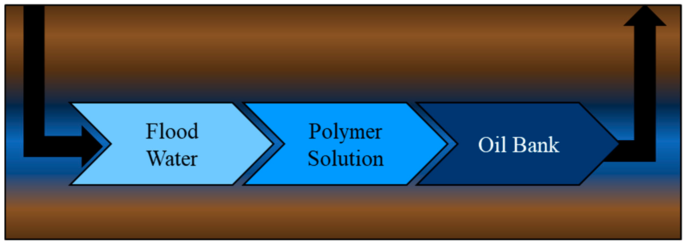
Figure 1. Simplified schematic of the polymer flooding process for enhanced oil recovery.
Processes 08 00361 g001
Figure 2. Effect of ionic polymer backbone on hydrodynamic volume; comparison of (a) polyacrylamide and (b) partially hydrolyzed polyacrylamide (HPAM).
Processes 08 00361 g002
Figure 3. Structure of (a) gradient (branched) copolymer, (b) random copolymer, and (c) block copolymer chains with comonomers A and B.
Processes 08 00361 g003
Figure 4. Capillary tube set-up for the determination of mechanical degradation (adapted from [12]).
Processes 08 00361 g004
Figure 5. Temperature distribution of global oil fields (as of 1998) (reproduced from Bjorkum and Nadeau [100] with permission from CSIRO Publishing).
Processes 08 00361 g005
Figure 6. Hypothetical conformation of an adsorbed polymer molecule on a rock surface (adapted from [129]).
Processes 08 00361 g006
Figure 7. Wall-effect model: water-based polymer with “water-wet” rock (adapted from [128]).
Processes 08 00361 g007
Figure 8. Experimental sand-pack system set-up for the evaluation of polymer flooding.
Processes 08 00361 g008
Table 1. Polyacrylamide-based materials for polymer flooding enhanced oil recovery (EOR).
Ref.Polymeric MaterialPolymer PropertiesPolymer Performance
[12]HPAM and
proprietary hydrophobically modified AAm-based copolymer
HPAM:
Degree of hydrolysis = 5%
MW = 8 × 10⁶ g/mol
Proprietary copolymer:
MW = 6×10⁶ g/mol
--Improved performance for proprietary copolymer over HPAM (more elastic properties, reformability, and high mobility control)
--Significant polymer retention in sand-pack tests (RRF = 165)
[24]PAAm with controlled molecular architecturesLinear, star, and comb structures; MW ranging from 2.8 × 10⁴ g/mol to 5.9 × 10⁵ g/mol--Molecular architecture impacts polymer solution viscosity
--Comb-like structures have higher viscosity and more elasticity than linear or star-like equivalents
[25]Salt-resistant HPAM derivatives with modified molecular architectureComb-shaped, branched, star-shaped, and hydrophobic-associating polymers
Degree of hydrolysis ~25%;
MW ranging from 10 × 106 g/mol to 25 × 106 g/mol
--Modified polymers have better salt tolerance (viscosifying ability, long term stability, and flow properties) than linear HPAM
--Some materials have been used in EOR, but results are not reported
[26,28]AAm copolymers and NNDAM copolymers with AAc or AMPS F ¯ A A m or F ¯ N N D A M ~ 0.60;
F ¯ A A c or F ¯ A M P S ~ 0.40
--NNDAM/AMPS had superior brine compatibility, shear stability, and thermal stability
--Flooding with NNDAM/AMPS allowed for incremental oil recovery up to ~11% (using 2000 ppm polymer solution)
[27]AAm copolymers with AAc, AMPS, or NVPAAm/AAc copolymer:
F ¯ A A m ~ 0.72;
MW = 18.5 × 10⁶ g/mol F ¯ A A m ~ 0.67;
MW = 12 × 106 g/mol
AAm/AMPS copolymers:
F ¯ A A m ~ 0.95;
MW = 6 × 10⁶ g/mol F ¯ A A m ~ 0.75;
MW = 8 × 10⁶ g/mol
AAm/NVP copolymer:
F ¯ A A m ~ 0.50;
MW = 6–8 × 10⁶ g/mol
--Higher molecular weight polymers were more shear-sensitive
--AAm/AMPS had the highest shear stability (larger AMPS proportion improved shear stability)
--AAm/NVP and AAm/AAc had similar shear stability (not as good as AAm/AMPS but better than PAAm)
[29]AAm/AMPS/VN terpolymer F ¯ A A m ~ 0.89; F ¯ A M P S ~ 0.10 (low concentrations of VN); low MW --Experimental evidence of temperature-thickening, pseudoplastic behavior, anti-shearing behavior, and brine compatibility
[30]AAm/AMPS copolymer (AN125) MW = 12 × 106 g/mol--0.2 wt % polymer solution in seawater exhibited RRF values up to 2.2; no plugging observed
[32]AAm/SAM/NABI terpolymerAAm/NABI copolymer sulfonated with HCHO and NaHSO3; F ¯ A A m > 0.95--Incremental oil recovery up to 10.6% in brine at 60 °C (using 7 g/L polymer solution)
[33]PAAm and
AAm/AH copolymer
PAAm:
MW = 5.0 × 10⁶ g/mol
AAm/AH copolymer:
F ¯ A A m ~ 0.66;
MW = 5.6 × 10⁶ g/mol
--Incremental oil recovery up to 20.0% with 2000 ppm copolymer solution in water (at 30 °C); achieved 18.7% in brine (at 80 °C)
--Incremental oil recovery up to 18.8% with 2000 ppm PAAm solution in water (at 30 °C); only 11.8% in brine (at 80 °C)
[34]HPAM and
AAm/AAc/NAE terpolymer
HPAM:
MW = 5×10⁶ g/mol
AAm/AAc/NAE terpolymer
synthesis conditions:
(AAm) = 16 wt %, (AAc) = 4 wt %, and (NAE) = 0.3 wt % (balance water)
--Incremental oil recovery from 1 g/L polymer solution (in brine at 65 °C):
HPAM: 4%
Terpolymer: 7.6%
[35,36]Crosslinked AAm/DBSV copolymerMW = 1.2 × 10⁶ g/mol~~ --Incremental oil recovery up to 20.8% (using 2 g/L polymer solution)
[37]Hydrophobically associating HPAM-based water-soluble polymerAAm-rich multicomponent polymer containing functional monomers (ACMO, HDDE, AMPS, and IBOMA)--Experimental evidence of heat resistance, salt tolerance, and good antimicrobial degradation performance
AAc = acrylic acid, AAm = acrylamide, ACMO = N-acryloyl morpholine, AH = acryloyl hydrazide, AMPS = 2-acrylamido-2-methylpropane sulfonic acid, DBSV = 4-dodecyl-benzenesulfonate-1-vinylimidazol-3-ium-divinyl sulfone, HDDE = N,N’-((2-hydroxy-4,5-dimethyl benzene-1,3-diyl) dimethanediyl) bisprop-2-enamide, IBOMA = isobornyl methacrylate, NABI = N-allylbenzamide, NAE = N-allyloctadec-9-enamide, NNDAM = N,N-dimethyl acrylamide, NVP = n-vinyl pyrrolidone, PAAm = polyacrylamide, SAM = sodium (acrylamido) methanesulfonate, VN = 2-vinylnaphthalene, HPAM = partially hydrolyzed polyacrylamide, MW = molecular weight, RRF = residual resistance factor, HCHO = formaldehyde, and NaHSO3 = sodium bisulfite.
Table 2. Potential biopolymers for polymer-flooding EOR (adapted from [7] with additional information from [18]).
BiopolymerAdvantagesDisadvantages
Carboxymethylcellulose
  • Water-soluble
  • Environmentally friendly
  • Oxidative decomposition
  • Thermal degradation
Cellulose
  • Thermal stability
  • Shear stability
  • Abundance of material
  • Not water-soluble
  • Heterogeneous swelling
Guar Gum
  • Good salt compatibility
  • Environmentally friendly
  • Potential for plugging
  • Thermal degradation
  • Weak elasticity
  • Precipitation from solution when Ca2+ concentration is high
Hydroxyethylcellulose
  • Water-soluble
  • Thermal stability
  • Shear stability
  • Good viscosity modification
  • Biodegradation
  • Limitations at low pH (hydrolysis of backbone)
  • Oxidative decomposition
Lignin
  • Low cost
  • Environmentally friendly
  • Not water-soluble
  • Biodegradation
  • Oxidative decomposition
  • Structure (and properties) are source-dependent
Schizophyllan
  • Water-soluble
  • Thermal stability
  • Good salt compatibility
  • Good viscosity modification
  • Nontoxic
  • Biodegradation
Scleroglucan
  • Thermal stability
  • Shear stability
  • Good viscosity modification
  • Environmentally friendly
  • Biodegradation
  • Oxidative decomposition
  • Poor filterability of material in porous media
  • High cost
Welan Gum
  • Long-term stability
  • Good viscoelastic properties
  • Higher viscosity and viscoelasticity than xanthan gum, even at lower molecular weights (network structure effect)
  • Affected by inorganic cations in reservoir
Xanthan Gum
  • Thermal stability
  • Shear stability
  • Good salt compatibility
  • Hardness resistance
  • Long-term stability
  • Biodegradation
  • Oxidative decomposition
  • Potential for plugging
  • High cost
Table 3. Typical range of experimental conditions for lab-scale testing (data from [97]).
ParameterHPAMsXanthan GumAssociating Polymers
Porosity (%)10 to 4410 to 4721 to 40
Permeability (mD)2.5 to 13,00018 to 6000300 to 12,600
Temperature (°C)22 to 12020 to 10022 to 93
Oil Viscosity (cP)1.7 to 55008 to 129140 to 18,700
Polymer MW (g/mol) 1 × 10⁶ to 25 × 1061 × 106 to 20 × 1061.3 × 106 to 20 × 106
Polymer Concentration (ppm)50 to 10,00030 to 2000500 to 3000
Water Salinity (ppm)250 to 133,470661 to 350,0005000 to 186,000
Table 4. Range of variables: polymer-flooding pilot tests (data from [97]).
VariableRange
Porosity (%)11 to 34
Permeability (mD)3.9 to 15,000
Temperature (°C)22 to 90
Oil Viscosity (cP)0.2 to 10,000
Polymer MW (g/mol)5 × 106 to 37 × 106
Polymer Concentration (ppm)200 to 2500
Polymer Viscosity (cP)1.35 to 40
Water Salinity (ppm)500 to 120,000
Table 5. Range of variables: field applications of polymer flooding [17,97].
VariableRange
Porosity, φ (%)4.0 to 37
Permeability, k (mD)>50
Temperature (°C)<99
Formation-water-salinity (ppm)<50,000
Concentration of divalent cations (ppm)<100
Reservoir lithologyMajority in sandstone reservoirs.
Very few in carbonate reservoirs.
Reservoir water cuts to start polymer flooding 95%
Clay content in reservoir rockLow
Oil viscosity, μ (cP)<5000
Oil saturation, So (%)>21
Injection well completionLarge diameter holes, high density, and deep penetration.
Hydraulic fracturing to reduce mechanical shearing of the polymer near the wellbore.
AquiferNone—weak
Gas capNone—weak
Polymer typeHPAMs and Xanthan Gum
Polymer MW (g/mol)
Reservoir permeability, k (mD)
12   ×   10 6   to   16   ×   10 6   g / mol   for   k   100 mD
17   ×   10 6   to   25   ×   10 6   g / mol   for   k   400 mD
Polymer injection rate (PV/year) Well spacing (m)0.14 to 0.16 PV/year—>250 m
0.16 to 0.20 PV/year—150 to 175 m
Addition of oxygen scavengers to polymer solutionsAlcohols, thiourea, sodium sulphite, and tri- or pentachlorophenol.
Addition of biocides to control biological degradationFormaldehyde