1. Introduction
Influenced by the global energy crisis, the penetration rate of the distributed power generation system using renewable energy is increasing. As the interface between most distributed energy and power grid, grid-connected inverters play an important role in transmitting power to the power grid [
1,
2,
3]. Unlike the synchronous generator (SG), the inverters based on power electronics technology have almost no internal inertia, which affects the stability of the power system and cannot provide frequency and voltage support for the power grid with distributed generation.
In order to make new energy that has a certain frequency support capability, the droop control strategy is usually adopted in the inverter [
4,
5,
6,
7]. The droop control is to simulate the droop characteristics of SGs. When the frequency and voltage of the systems change, the output active power and reactive power of inverters change according to the droop characteristic. However, the droop control only simulates the primary frequency regulation and the primary voltage regulation characteristics of the SG. The inertial support capability of the SG is not realized.
In the power system, because the rotor of the SG has inertia, the frequency fluctuation can be restrained and the stability of power grid operation is enhanced. According to this idea, the concept of virtual synchronous generator (VSG) is proposed in References [
8,
9,
10,
11,
12,
13]. By introducing the mechanical and electromagnetic equations of the SG, its mechanism and external characteristics are simulated by the inverter.
However, the addition of virtual inertia may aggravate the oscillation of active power after a disturbance. Therefore, the proper damping effect needs to be introduced into VSG [
10,
11]. In Reference [
12], the damping algorithm proposed by linear control theory can effectively avoid the low-frequency oscillation after disturbance. In Reference [
14], various kinds of damping effect in VSG are compared. A generalized droop control strategy is proposed. According to the dynamic response requirements of VSG frequency and output power, the zero and pole positions of the closed-loop transfer function are set. In Reference [
15], the damping power includes the frequency deviation, the output power, and the integral of the damping power multiplied by their respective proportional coefficients. According to the desired closed-loop eigenvalue of the system, the coefficients are obtained by the state feedback method. In Reference [
16], a differential term for the output power is added to the active power loop, and the damping ratio of the system can be freely adjusted without affecting the steady-state frequency droop characteristics.
In addition to the above fixed-parameter strategies, some adaptive parameter methods are also proposed. In Reference [
17], the relationship between the damping coefficient and frequency stability is summarized. Then, an adaptive damping algorithm based on frequency deviation is presented. However, the damping coefficient only increases when the frequency tends to be steady. The effect of the damping coefficient is not fully exerted. In Reference [
18], the damping coefficient increases exponentially based on the frequency deviation, so that the overshoot of the output power can be reduced, but the damping coefficient increases only when the frequency deviation is large. The damping coefficients in the most existing literature is set according to the preset maximum frequency deviation. However, in the actual process, the frequency may not reach the preset maximum deviation value. The control capability of the inverter is not fully utilized.
In this paper, the influence of damping on the dynamic characteristics and steady-state performance of VSG system is analyzed. The maximum deviation of the frequency is dynamically measured. The damping coefficient is adjusted based on the maximum frequency deviation. The dynamic characteristics of the frequency response are improved. Through VSG active power loop and small-signal mathematical model, the range of the damping coefficient is determined. Finally, the damping algorithm in this paper is compared with the fixed damping method and the damping method based on the frequency deviation. The effectiveness of the proposed algorithm is verified by the simulation experiment with MATLAB/Simulink.
2. Basic Principles of VSG
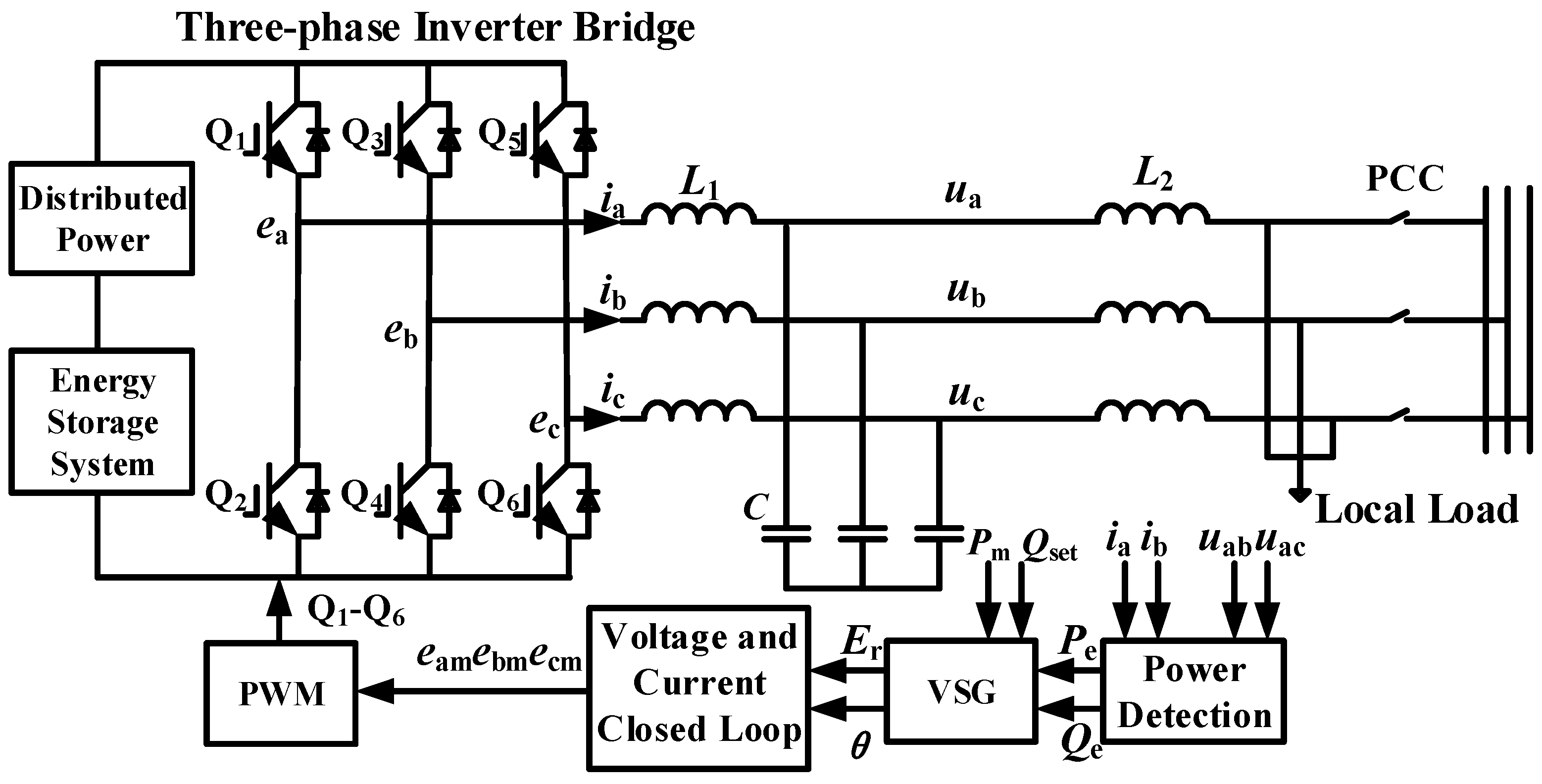
Figure 1 is the main circuit topology and control block diagram of grid-connected inverters. It mainly includes distributed power, energy storage system, three-phase inverter bridge, LCL filter, and local load. The LCL filter is composed of the inverter-side inductor
L1, the filter capacitor
C, and the gird-side inductor
L2. The output voltage
ua,
ub,
uc and current
ia,
ib,
ic of the LCL filter are calculated to get the output active power
Pe and the output reactive power
Qe. The reference voltage
Er and power angle
θ are calculated by substituting the set active power
Pm and reactive power
Qset into the VSG control module. Three-phase modulation waves
ema,
emb,
emc are obtained through voltage and current closed-loop control. Three-phase modulation waves drive each switch of three-phase inverters through pulse width modulation (PWM).
The rotor motion equation of the SG is simulated by the active power loop, which makes the distributed generation have the basic characteristics of the SG. In addition, no excessive transient process is introduced. Therefore, the second-order model of the SG is adopted, as shown in Equation (1).
Here, J is the virtual inertia, which represents the inertia effect of SGs, here is a parameter of the inverter. Pm is the set value of active power. Pe is the output active power. When the number of pole pairs p = 1, the mechanical angular velocity ω of the SG is the electrical angular frequency. ω0 is the rated angular frequency. ωg is the grid angular frequency. Dp is the damping coefficient of the inverter, which represents the function of the damper winding. θ is the power angle of the SG.
In Equation (1), the damping power is realized by simulating the effect of the damping winding. This requires the addition of a phase-lock loop (PLL) to detect the grid frequency. However, the addition of PLL will delay the dynamic response of VSG and even affect the stability of the system [
15]. Therefore, the rated frequency
ω0 is usually used to replace the grid frequency
ωg to generate damping power
PD, as shown in Equation (2).
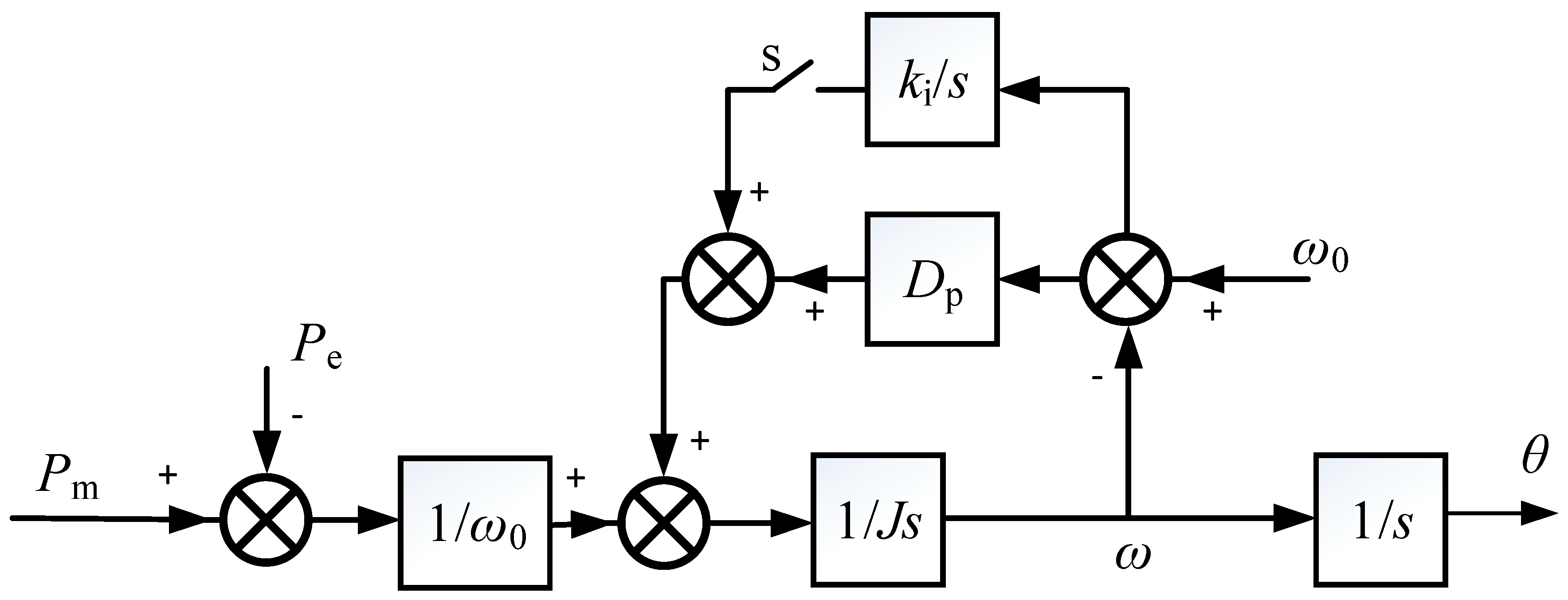
In the island mode, the integrator
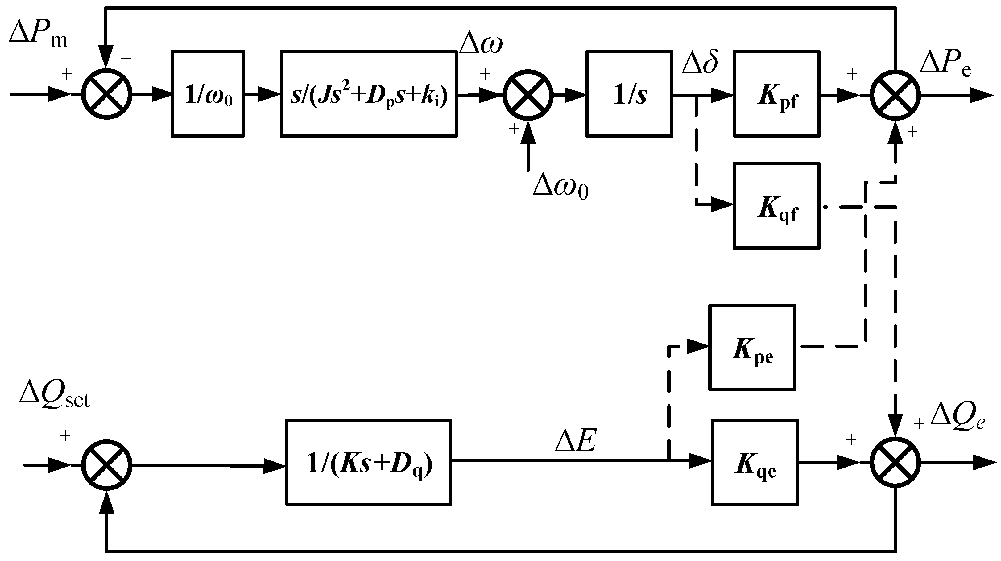
ki/s is added to the active power loop.
ki is the integral term coefficient. The PI regulator in the active power loop is composed of the integral term and the damping factor
Dp, to realize the undifferentiated tracking of the rated frequency. The active power loop control block diagram is shown in
Figure 2.
In order to change the output reactive power
Qe according to the set value
Qm, the virtual electromotive force amplitude is obtained by integrating the reactive power deviation. The reactive power loop control equation is shown in Equation (3).
where
E is the virtual electromotive force amplitude;
K is the reactive power integral coefficient;
Qset is the reactive power reference value;
Dq is the voltage adjustment coefficient;
Un is the rated voltage amplitude;
Uo is the output voltage amplitude.
3. Adaptive Damping Control Strategy
In general, the damping factor is set according to the fixed maximum frequency deviation. However, in the dynamic process of frequency change, the preset maximum deviation of the frequency may not be reached. According to the damping obtained by the preset maximum deviation, the role of the controller cannot be fully exerted. Therefore, the damping coefficient is dynamically adjusted according to the actual maximum frequency deviation in this paper. The dynamic performance of the frequency is improved.
When the damping power is expressed by Equation (2), in the grid-connected mode, the output frequency of VSG follows the grid frequency. When the grid frequency is not equal to the rated frequency, the damping power is not equal to zero, so the primary frequency modulation characteristic of the system is coupled with the damping term. In this case, an integral term of the damping power can be added to the damping power, so that the damping power is equal to zero when the frequency returns to the stability. Therefore, the damping coefficient will also affect the steady-state performance of the system, but the influence of the damping on the steady-state situation can be eliminated by changing the VSG active power loop structure.
The damping coefficient Dp of a traditional generator has a certain range and is a fixed parameter. Due to the flexibility and controllability of the inverter, the simulation of the damping parameter of the VSG is not limited by physical conditions. The damping coefficient can be dynamically adjusted according to the real-time response information. When the damping coefficient Dp is too small, although the system response speed is increased, it will cause a large overshoot of the system frequency. When Dp is too large, the overshoot and settling time of the frequency response can be reduced, but the influence on frequency droop control and power distribution may be aggravated.
When load disturbance occurs in VSG system, the system frequency will oscillate at the moment of disturbance. The overshoot and the settling time (referring to the shortest time when the frequency enters and maintains in the steady-state interval) of oscillation are two key indicators to judge the frequency stability of the system. The closed-loop transfer function of the frequency loop in VSG is a second-order system. When the value of
Dp is in the under-damped range, according to the automatic control principle [
19], the overshoot and the settling time of frequency response decrease with the increase of
Dp. Thus, the stability of system frequency can be enhanced by increasing
Dp in a certain range.
The standard EN 50438 [
20] specifies that the continuous operation condition of the inverters connected to the power grid. The frequency of the power grid is maintained between 49 Hz and 51 Hz. Meanwhile, in order to suppress the oscillation of active power and frequency of VSG in the dynamic process, the damping coefficient should be proportional to the rated capacity of the inverter. According to the above criteria, the initial damping coefficient setting principle is obtained. The rated capacity of a single inverter is assumed to be 10 kV·A. When the power grid frequency deviation ∆
fN is equal to 1 Hz, the output active power of the inverters changes 100% (∆
Pmax = 10 kW).
In Equation (4), ∆
Tmax is the maximum torque variation, ∆
Pmax is the maximum change of active power, and ∆
ωmax is the maximum frequency variation.
The fluctuation range of the frequency after disturbance cannot be predicted, so ∆
fN is used as the maximum value of frequency variation to set
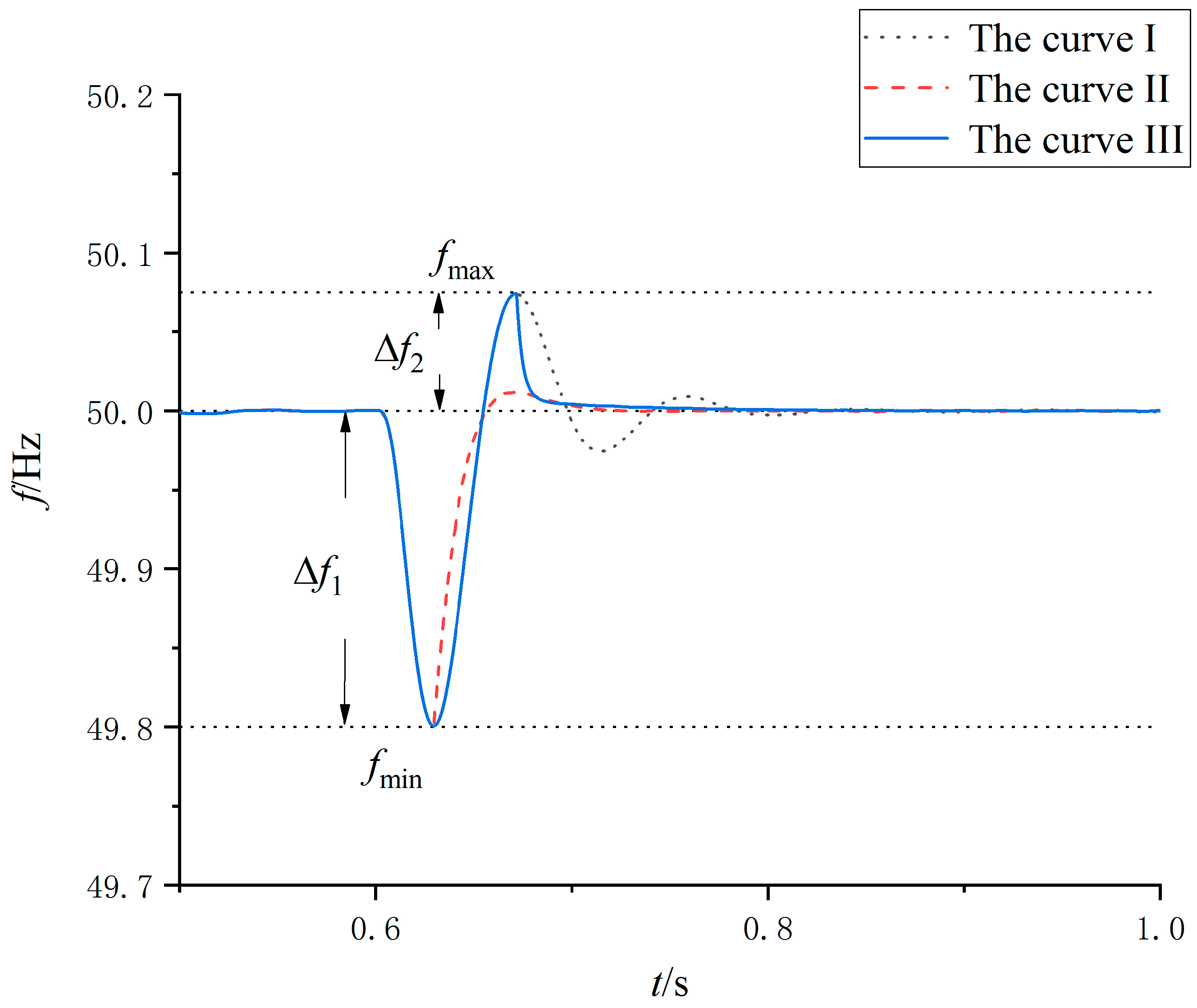
Dp. As shown in
Figure 3, the active load suddenly increases at a certain time, and the frequency drops to the minimum value
fmin. At this time, the deviation between the frequency and the steady-state value is ∆
f1. This frequency is less than the maximum allowable variation of the frequency ∆
fN. After the frequency reaches the minimum value for the first time, ∆
f1 can be used instead of ∆
fN to set a new damping coefficient
Dp1 as shown in Equation (5). The relationship between the maximum frequency deviation and the damping is dynamically considered. This damping coefficient is about 5 times that of the initial value so that the frequency response has a shorter settling time and a smaller overshoot.
When the frequency rises from the minimum
fmin to the maximum
fmax, the difference between the maximum
fmax and the steady-state value is ∆
f2. At this time, ∆
f2 can be used instead of ∆
f1 to set a larger damping coefficient. The oscillation of the frequency is greatly slowed down, and the frequency is returned to the steady-state interval more quickly. In
Figure 3, the initial damping of three curves is the same. The damping coefficient of the curve I is a fixed initial value. The damping of the curve II is set to
Dp1 at
fmin and kept at that value. The damping coefficient of the curve III is changed to
Dp2 at
fmax and the value is maintained until the end.
The setting process of the damping coefficient is as follows:
If the frequency is disturbed and the absolute value is greater than 0.02 Hz, the evaluation is started.
When the frequency reaches the extreme value each time, use the frequency deviation ∆f at this time to set a new damping coefficient.
Compare the setting damping with the preset maximum value. If it is greater than the maximum value, set it according to the maximum value.
When the frequency is kept in a stable interval for 2 s, the damping coefficient returns to the initial value.
The setting method of the maximum value will be given in the next chapter.
5. Simulation Results
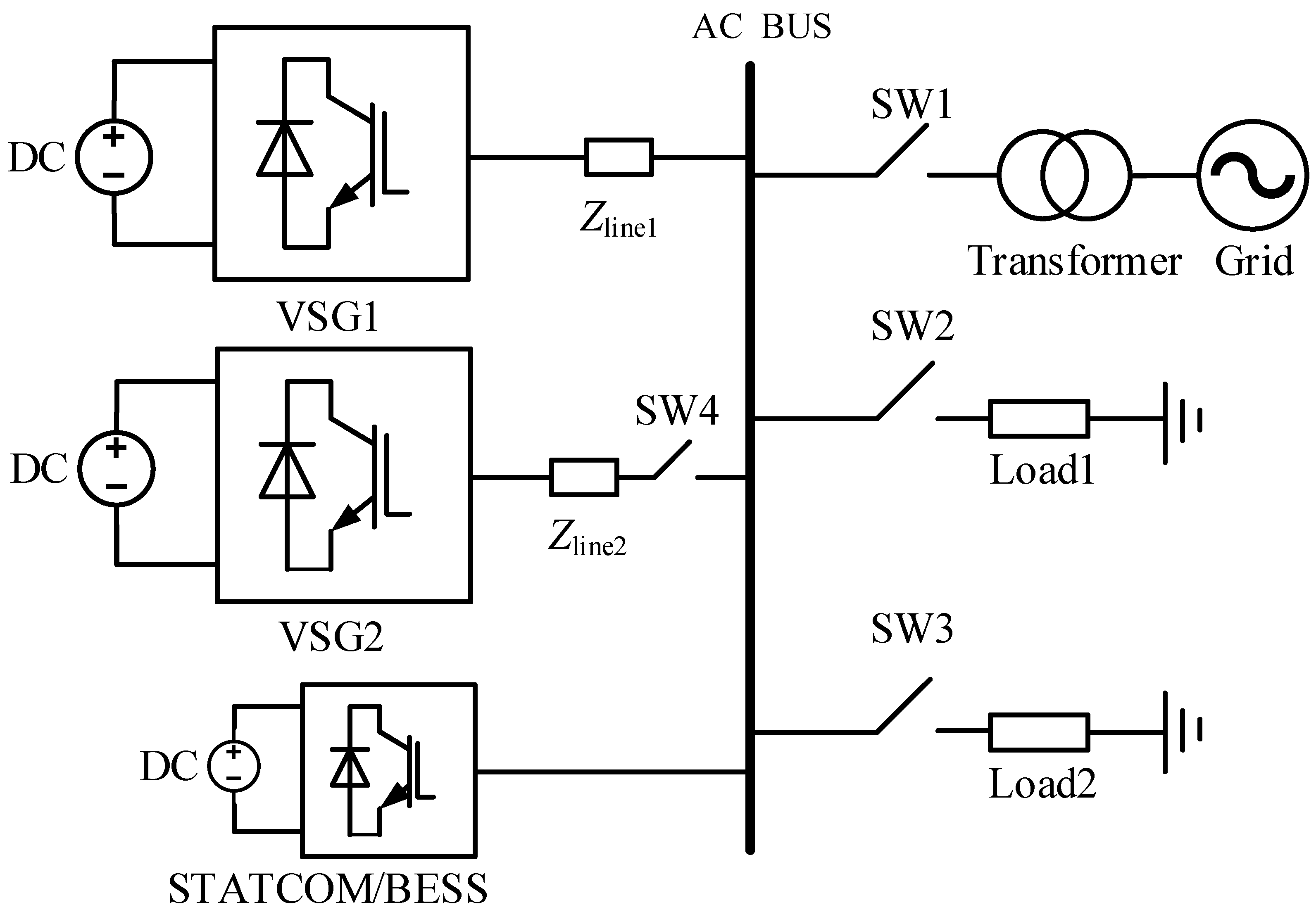
In order to verify the effectiveness and compatibility of the adaptive damping control strategy, a microgrid simulation platform is built by MATLAB/Simulink software, as shown in
Figure 6. The inverters are all adopted the VSG strategy, and the capacity of the two VSGs is the same. In the island mode, two VSGs are connected in parallel to load. In the grid-connected mode, only VSG 1 is connected to the grid. The simulation parameters are shown in
Table 1.
In
Figure 6, the static synchronous compensator (STATCOM) can quickly output bidirectional reactive power. It consists of a DC-side capacitor and a voltage-type inverter. To ensure the stability of the output voltage amplitude, it is necessary to absorb active power from the grid to compensate for its energy loss, so it does not have active power adjustment abilities. The STATCOM with battery energy storage system (BESS) can not only quickly compensate reactive power but also provide active power support so that it can achieve more flexible power adjustment functions.
5.1. Effectiveness Test
In the island mode, through the change of the load power, the frequency stability problem caused by the system load fluctuations is simulated. Under the same simulation conditions, the control strategy of this paper is compared with the constant damping strategy (CD) and the damping strategy set based on frequency deviation (FD) [
17].
For the CD strategy, Dp is set to a fixed value of 5 Nm·s/rad. For the FD strategy, the steady-state value is set to 5 Nm·s/rad. For the self-adaptive damping strategy proposed in this paper (SAD), the initial damping is set to 5 Nm·s/rad. The virtual inertia is constant, and its value J0 is set to 0.2028 kg·m2.
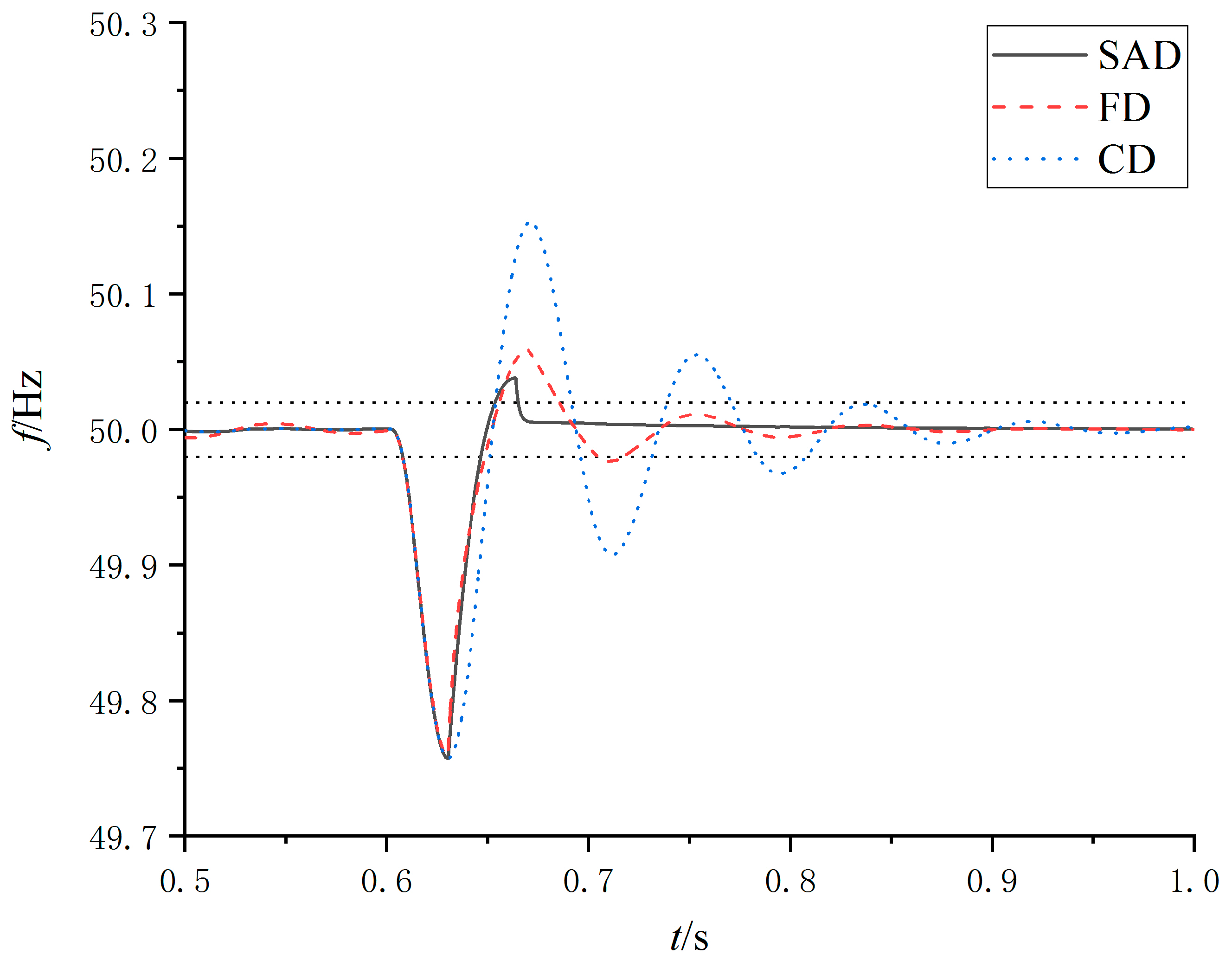
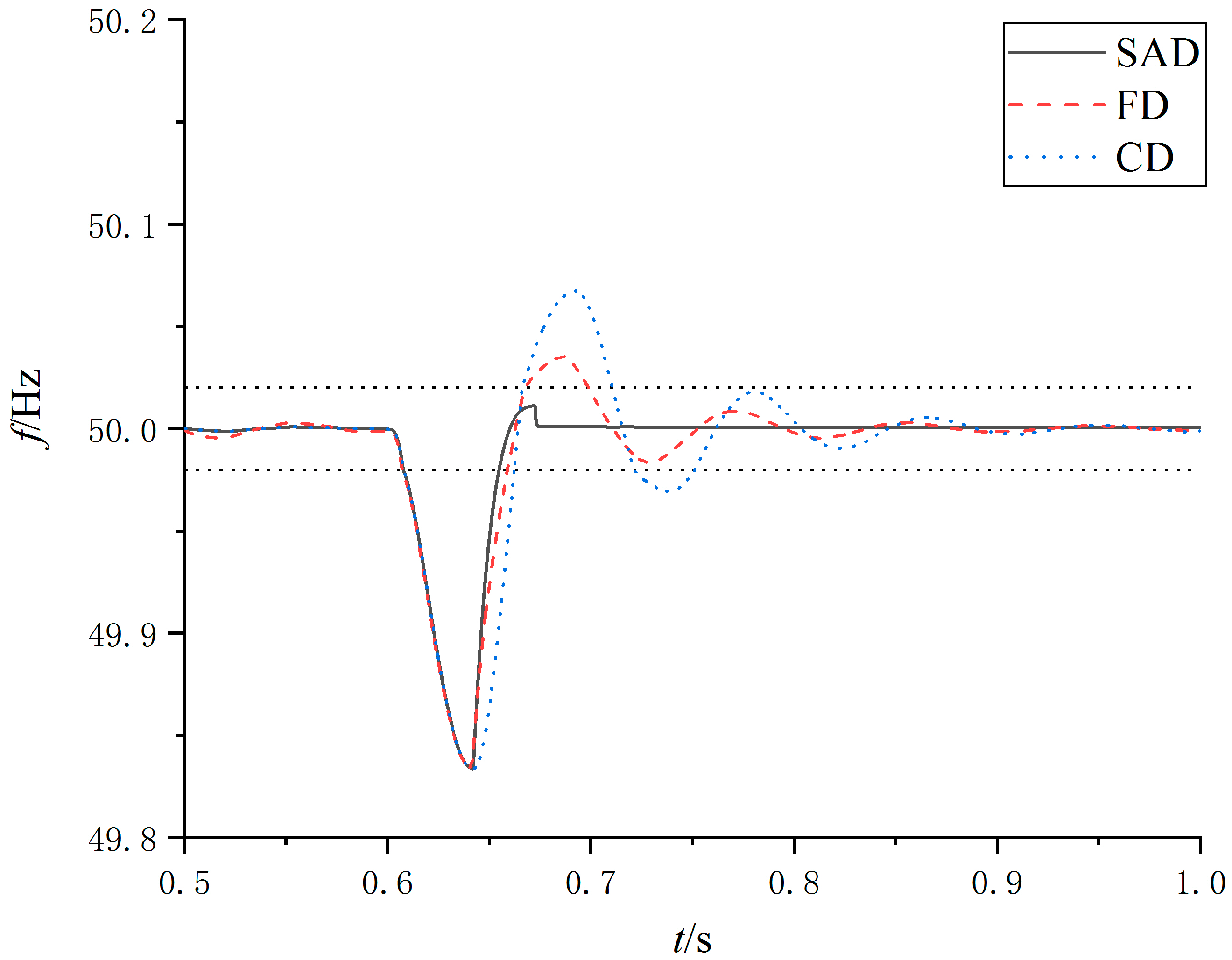
For a simulation of the sudden increase of load power, the active load rises from 2 kW to 10 kW at 0.6 s.
The control effects of VSG 1 under three control strategies are shown in
Figure 7. For the SAD strategy, the frequency is stable in the steady-state interval (±0.02 Hz) at 0.665 s. For the FD strategy, the frequency is maintained in the steady-state range after 0.717 s. For the CD strategy, the frequency is maintained in the steady-state range after 0.807 s. It shows that the SAD method has a shorter settling time. The oscillation energy of frequency is quickly consumed by damping. The frequency overshoot is reduced in the second swing. The settling time and overshoot of each control strategy are shown in
Table 2.
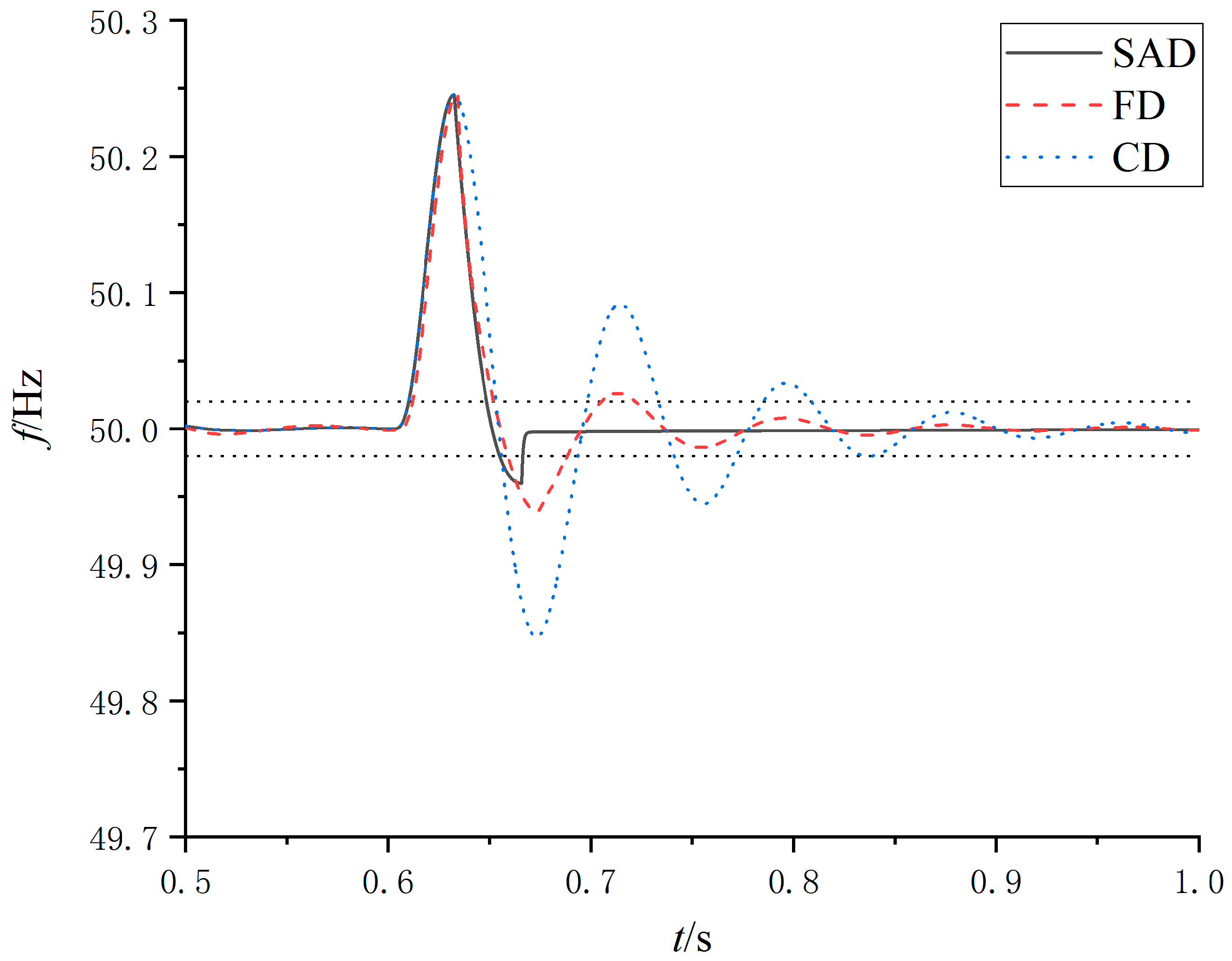
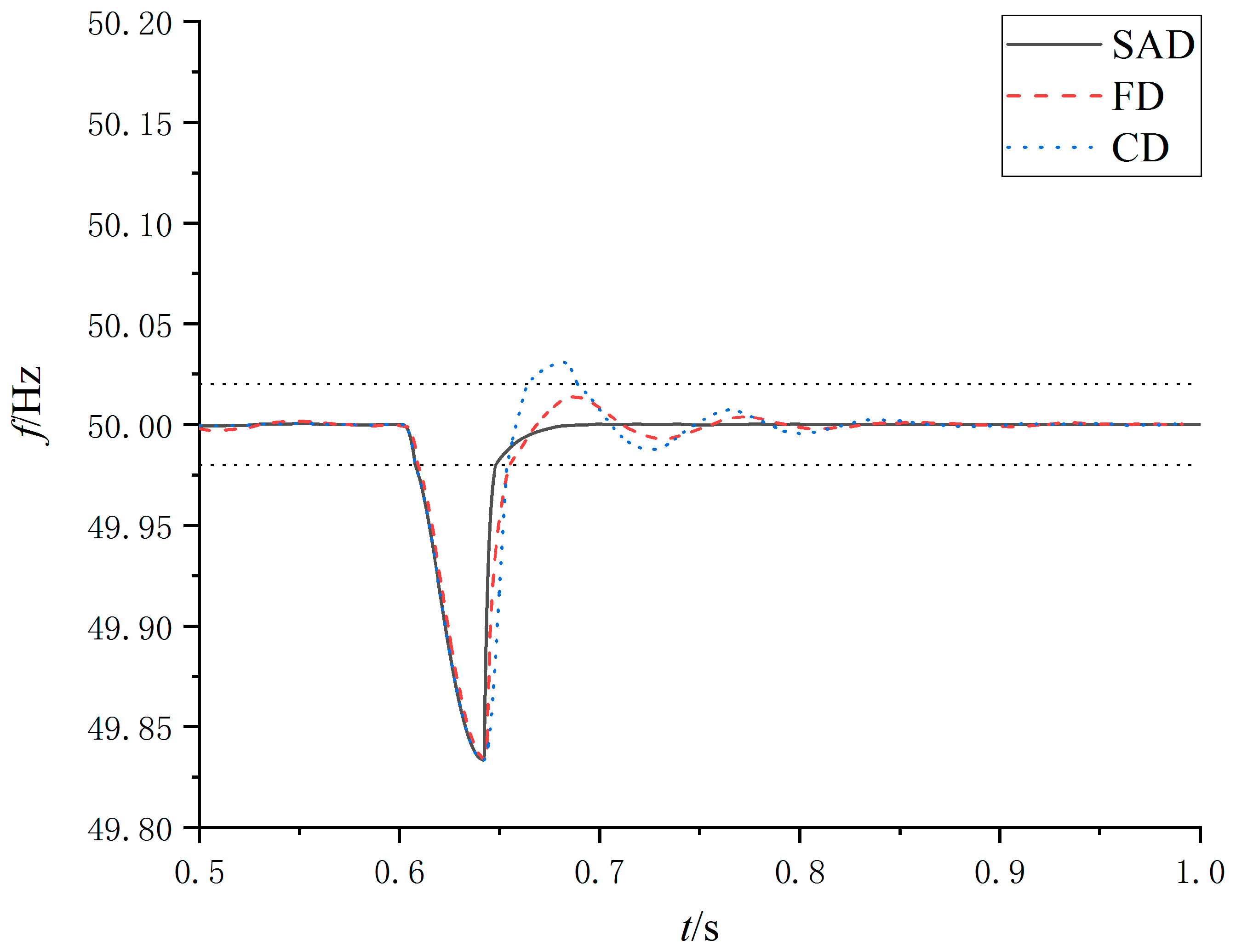
For a simulation of the sudden decrease of load power, the active load drops from 10 kW to 2 kW at 0.6 s. The control effects of VSG 1 are shown in
Figure 8.
In
Figure 8, when the load is suddenly reduced, the control effects of three strategies are the same as that of the sudden load increase. Compared with the other two strategies, the SAD strategy has less settling time and less overshoot.
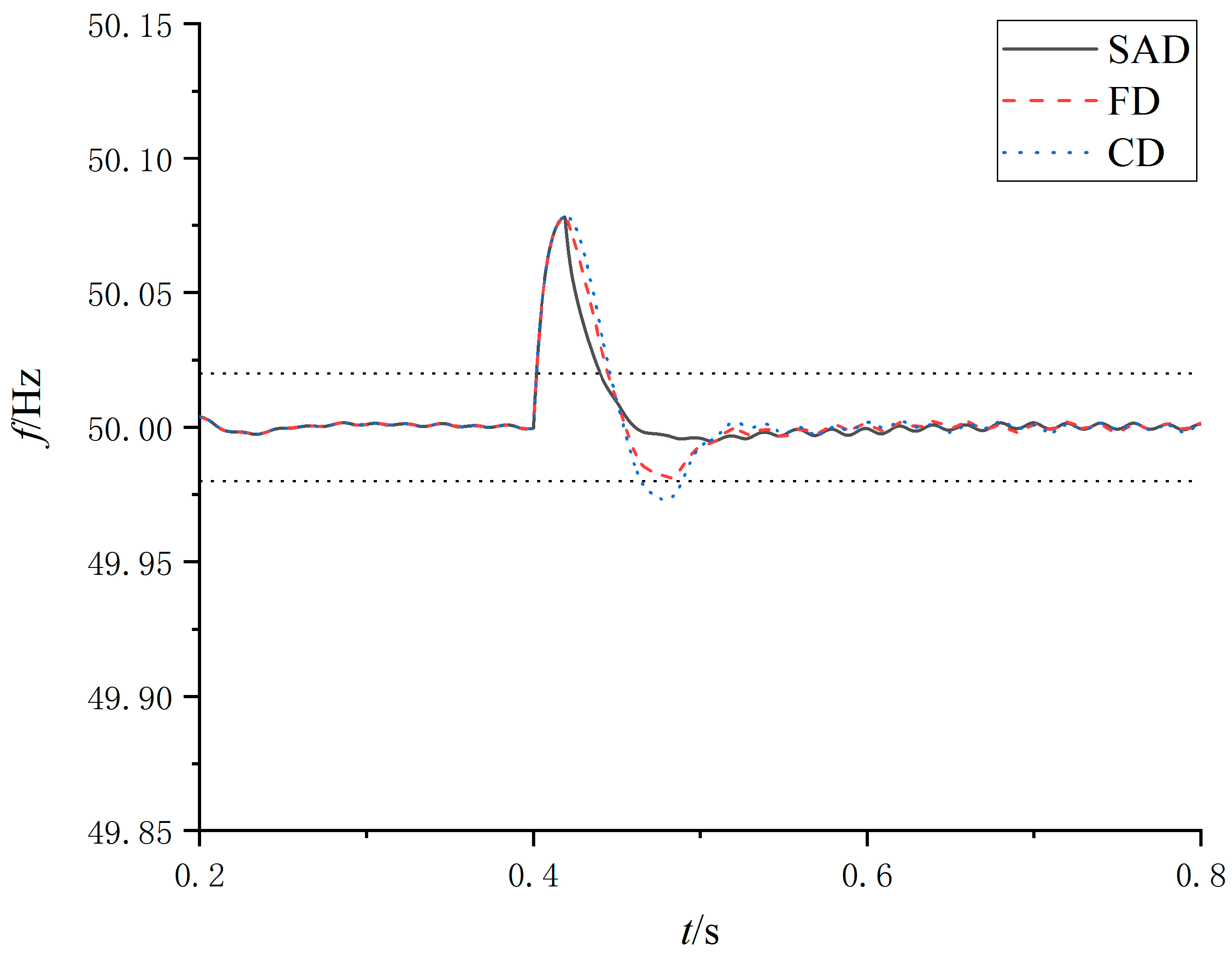
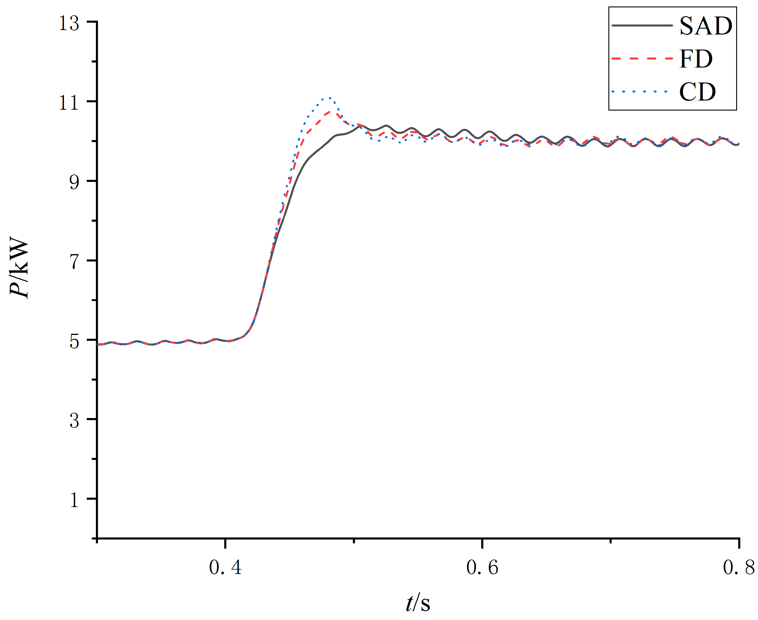
In the grid-connected mode, first, VSG1 operates independently with two loads. The pre-synchronization control is turned on at 0.1 s to avoid power impact when grid-connected and island modes are switched. The active power reference of VSG 1 increased from 5 kw to 10 kw in 0.4 s. The output frequency and active power of VSG1 are shown in
Figure 9 and
Figure 10.
In
Figure 9, for the SAD strategy, the frequency returns to the steady-state interval faster and does not even require a second tuning. In
Figure 10, the larger damping prevents the output power from overshooting and can reach the given value in time.
5.2. Compatibility Test
In order to verify the compatibility of the strategy in this paper, the damping strategy is combined with virtual inertia strategy set based on frequency change rate [
17]. The three damping control strategies are the same as the above effectiveness test. The simulation system operates in the island mode. The active load rises from 2 kW to 10 kW at 0.6 s. The control effects of VSG 1 are shown in
Figure 11.
In
Figure 11, under the SAD strategy, the frequency response has a smaller overshoot and a shorter settling time compared with the other two strategies. The settling time and overshoot of each control strategy are shown in
Table 3.
The damping strategy is combined with virtual inertia of bang-bang control strategy [
11]. The simulation conditions are the same as the previous case. The control effects are shown in
Figure 12.
In
Figure 12, under the SAD strategy, the frequency has no overshoot after first returning to the steady-state interval. Moreover, the frequency enters the steady-state interval faster than the other two strategies.
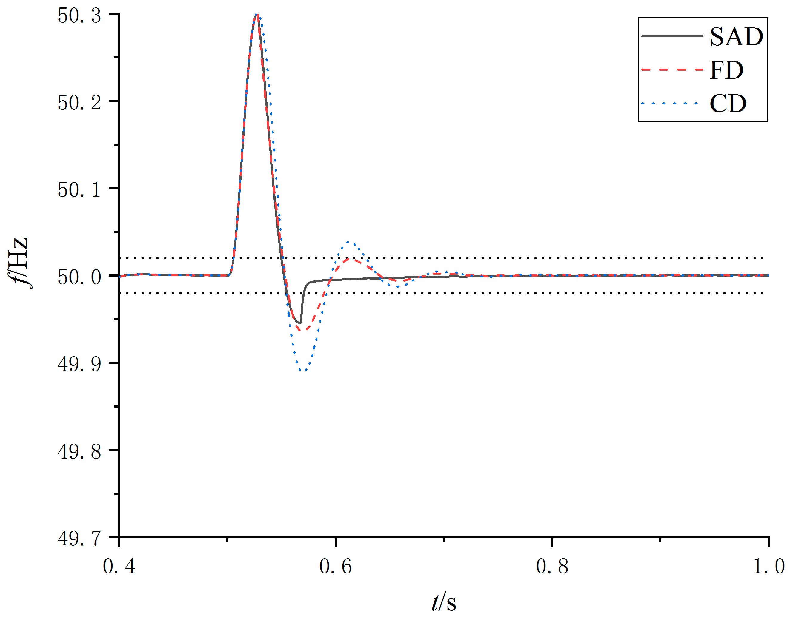
In order to verify the applicability of the SAD strategy in the event of grid fault, the short-circuit fault in a microgrid is taken as an example. The ability of the inverter frequency recovery under different strategies is compared. The system operates in the island mode, and the initial active load is 15 kW. The three-phase short-circuit fault occurs at 0.5 s for load 1. The output frequency of VSG 1 is shown in
Figure 13.
It can be seen from
Figure 13 that in case of a short-circuit fault in the grid, under the SAD method, the VSG frequency can become stable faster than the other two methods.
Under the SAD control strategy, the VSG frequency has a good dynamic response in the grid-connected or island mode. Moreover, this strategy can be combined with different virtual inertia control strategies. These simulations prove the effectiveness and compatibility of the SAD strategy.


