Article

Numerical Study of Binary Trickle Flow of Liquid Iron and Molten Slag in Coke Bed by Smoothed Particle Hydrodynamics

1
Institute of Multidisciplinary Research for Advanced Materials, Tohoku University, Katahira 2-1-1, Aoba-ku, Sendai, Miyagi 980-8577, Japan
2
Faculty of Engineering, Hokkaido University, N13-W8, Kita-ku, Sapporo, Hokkaido 060-8628, Japan
3
Department of Materials Science and Engineering, Faculty of Engineering, Kyushu University, Motooka 744, Nishi-ku, Fukuoka 819-0395, Japan
4
Magnetic Powder Metallurgy Research Center, National Institute of Advanced Industrial Science and Technology, 2266-98 Anagahora, Shimo-Shidami, Moriyama-ku, Nagoya, Aichi 463-8560, Japan
*
Author to whom correspondence should be addressed.
Processes 2020, 8(2), 221; https://doi.org/10.3390/pr8020221
Submission received: 16 January 2020 / Revised: 10 February 2020 / Accepted: 12 February 2020 / Published: 14 February 2020
(This article belongs to the Special Issue Process Modeling in Pyrometallurgical Engineering)

Abstract

:
In the bottom region of blast furnaces during the ironmaking process, the liquid iron and molten slag drip into the coke bed by the action of gravity. In this study, a practical multi-interfacial smoothed particle hydrodynamics (SPH) simulation is carried out to track the complex liquid transient dripping behavior involving two immiscible phases in the coke bed. Numerical simulations were performed for different conditions corresponding to different values of wettability force between molten slag and cokes. The predicted dripping velocity changes and interfacial shape were investigated. The relaxation of the surface force of liquid iron plays a significant role in the dripping rate; i.e., the molten slag on the cokes acts as a lubricant against liquid iron flow. If the attractive force between the coke and slag is smaller than the gravitational force, the slag then drops together with the liquid iron. When the attractive force between the coke and slag becomes dominant, the iron-slag interface will be preferentially detached. These results indicate that transient interface morphology is formed by the balance between the momentum of the melt and the force acting on each interface.

Graphical Abstract

1. Introduction

An efficient trickle flow of high-temperature melts in coke beds is necessary in ironmaking blast furnaces, as it ensures a smooth continuous process, which is a prerequisite for high productivity in operations that use lower amounts of reducing agents. The trickle flow is driven by the gravitational force that acts on the liquid iron and molten slag (two immiscible liquids), and the dripping behavior is balanced by viscous and interfacial forces. When the volume of the high-strength coke, which acts as a spacer in the lower part of the blast furnace, is reduced, the resistance to the melt passage increases, which can cause instability. It is, therefore, essential to maintain a desired trickle flow through the coke bed to prevent clogging problems that may occur if the pressure drop in the bed becomes excessive or shows large variations. This approach emphasizes the need to understand the dripping behavior of the two liquids in the coke bed.
Over the years, liquid flow in blast furnaces has been investigated experimentally and mathematically. Several studies focused on the volume fraction of the liquid in the packed bed, called “liquid hold-up”, and the effect of various in-furnace conditions, including the physical properties of the liquid and the wettability of coke. The relationship between hold-up and dimensionless number has been determined by applying an experimental system using room temperature media [1,2,3] or actual melt [4,5,6]. Since the hold-up of CaO-SiO2-Al2O3-based molten slag (>1773 K) is significantly affected by the wettability of coke [7], several experimental studies have been conducted on the static contact angle between molten slag and “carbonaceous material” [8,9,10]. The molten slag wetting behavior relatively depends on the carbonaceous material substrate, i.e., not only the equilibrium contact angles but the periods to reach a stable contact angle vary considerably. If basicity (CaO/SiO2 mass %) ≤ 1, the decrease in the contact angle with time as the basicity decreases is generally attributed to the formation of interface product SiC [11], but the change in the state of the Fe-Si-C system is still unclear because this change depends on the Si form (which may exist in a gaseous form). In investigating coke-slag wettability, the differences in small amounts of components (such as FeO and MgO) in slag and the differences in the specific properties (such as crystal structure and void structure) of carbonaceous substrates should be considered.
Computational fluid dynamics (CFD) is useful for understanding this phenomenon. The advantage of this approach is the precise tracking of time-varying fluid interfaces, which is difficult to observe experimentally. Most recent CFD studies demonstrate that, with regard to the wettability of the packed bed, the geometry of the bed has a significant effect on the interface dynamics, leading to the co-existence of complex interfaces; thus, the change in wettability leads to various interfacial movements that are unidentified under static conditions. Molten slag flow in a packed coke bed was investigated by using the three-dimensional combined discrete element method (DEM) and CFD [12,13,14]. A series of two-dimensional [15,16] and three-dimensional [17] high-resolution direct numerical simulations were also conducted with the aim of understanding the pore-scale fluid dynamics. Although the two-liquid flow in packed beds has received attention but usually focused on room temperature media [18,19], there is no guarantee that the information available from the water-oil-rock system can be applied to the slag-iron-coke system in blast furnaces. For example, the density difference between iron and slag (≈4000 kg/m3) is considerably higher than that of water and oil (≈200 kg/m3) [20]. It is essential to evaluate the interfacial force in an unsteady condition under the condition where the momentum in the gravity direction appears. CFD studies have been conducted for such cases. The phase field modeling for the behavior of molten slag confirmed that the increment of the interfacial tension between liquid iron and molten slag was the driving force of the molten slag separation from the melt [21]. Using the volume of fluid simulation, the driving force of the liquid iron penetration into the coke bed was proposed due to the total energy reduction by extending the area covered with the liquid iron [22]. On the other hand, the fully Lagrangian approach, which can track moving calculation points, has been adopted for solving multi-fluid physics problems during high-temperature metallurgical processes with complicated interfaces [23,24]. The smoothed particle hydrodynamics (SPH) method discretizes a continuous fluid phase by moving particles and is suitable for analyzing interfacial flow, even for numerous dispersed phases. This method can track the dripping flow [25], the movement of both the gas and the liquid phase [26], fluid flow in bed structures having different shapes (coupled with multi-sphere DEM) [27,28], and solid particle penetration into the liquid iron bath [29,30] directly. Recently, with the increase in computer capacity, the SPH method has been applied to very complicated interface problems [31]. For convenience, surface forces are converted into body forces in the SPH method, but recent expansions in computer capacity have alleviated this weakness. In this study, the trickle flow of a liquid iron and molten slag was simulated in the lower part of the blast furnace, and the effect of the wettability of molten slag and coke was investigated.

2. Methods

2.1. Basic Formulation of SPH

From the basic idea of SPH, it is evident that fluid motion is represented using a set of particle motion equations. A kernel function is introduced as an integral interpolation to solve a differential equation. In other words, the formulation is based on an interpolation scheme that allows the estimation of a vector or scalar function f at position r in terms of the values of the function at the discretization points.
f ( r ) f ( r ) W ( r , h ) d V
In Equation (1), r denotes arbitrary coordinates, r denotes particle positions, V denotes the volume, W is the smoothing kernel function, and h is the radius of influence. The summation of function f can be replaced with a summation over particles only within the distance h from r i owing to the compactness; thus, W ( r i j , h ) = 0 when | r i j | > h . The kernel must possess a form symmetrical to | r i j | = 0 . Here, i is the particle index, and j is the index of the neighboring particle around i . The kernel has at least a continuous first derivative and must satisfy the normalization condition as W   ( r i j , h )   d r = 1 . Within the h 0 limit, the kernel is required to reduce to a Dirac delta function δ ( r i j ) . Wendland’s kernel can be applied to prevent having various kernel artifacts in a multiphase system [32]:
W ( r i j , h ) = 21 16 π h 3 { ( 1 q 2 ) 4 ( 2 q + 1 ) , q < 2 0 ,        q 2
where | r i j | 0 is the interparticle distance corresponding to the initial conditions, q = | r i j | / h , and it is assumed that h = 1.05 | r i j | 0 [27]. The gradient form of Equation (1) can be represented by using the divergence theorem as follows:
f ( r ) f ( r ) W ( r , h ) d V
When applying this approximation to dispersed fluids, the discontinuities in the density distribution of the fluids become significant, which increases numerical errors. Nonuniform distribution or insufficiency of particles in the regions near the interface results in a significant fluctuation of pressure. The moving least squares (MLS) method is useful for approximating the function to solve this problem [33], which is related to the numerical fluctuations in the pressure at the nearby interface. The pressure is a function of the local density, and thus, the smooth density field of a bulk phase leads to a continuous pressure distribution. The MLS method improves the mass-area-density consistency and filters small-scale pressure oscillations, as described briefly in the following section.

2.2. Density Approximation

The SPH formulation can be transformed into a particle-based format to express the mass-area-density consistency process. The density of the particles was expressed in terms of the sum of the kernel functions of the N particles present within the radius of influence as follows:
ρ i = j = 1 N m j W ( r i j , h )
where the subscripts i and j denote the particle indices, m is the mass, and ρ is the local density around the particle. Further, m j is the mass of particle j. Therefore, the kernel function around particle i can be discretized using the following equation, which is derived from Equations (1)–(3):
f i ( r ) = j = 1 N m j ρ j f ( r j ) W ( r i j , h )
The gradient of f i can be represented as expressed in Equation (6):
f i ( r ) = j = 1 N m j ρ j f ( r j ) W ( r i j , h )
MLS involves a first-order consistent gradient approximation, which allows pressure smoothing, and its first derivative values are obtained using the method for the homogenous bulk phase mentioned above. The method of the least square interplant with constraint condition (CLS) represents an improved scheme, leading to a more accurate approximation than the MLS method around the sampling points [33,34]. In the CLS method, the particles can be made to directly represent a physical quantity by extending the MLS method in the one-dimensional error space for multiple dimensions. In the three-dimensional space, the CLS method approximates the values of various physical parameters around the particles based on the following equation: ρ i = a 0 + a 1 ( x x i ) + a 2 ( y y i ) + a 3 ( z z i ) , where, x, y, and z are the coordinates of the sampling points and a 0 ,   a 1 ,   a 2 , and a 3 are the undetermined coefficients. If x = x i , y = y i , and z = z i , then ρ i = a 0 at particle i. Refer to a previous report for parameters determining the procedure [26].

2.3. Fluid Motion Equation and Discretization

The governing equations for a weakly compressible viscous flow are based on the relationship between the velocity of sound and the flow density under adiabatic conditions, as well as the Navier-Stokes Equations:
( D p D ρ ) S = c 2
ρ D v D t = p + μ 2 v + ρ + F s
where v is the fluid velocity, p is the pressure, c is the velocity of sound, μ is the viscosity, and F s is the interfacial force. Subsequently, Equation (8) can be formulated for each particle as follows:
m i D v i D t = j = 1 N ( p i V i 2 + p j V j 2 + Π i j ) W i j + j = 1 N 2 μ i μ j μ i + μ j ( V i 2 + V j 2 ) r i j | r i j | 2 v i j W i j + m i g + F s i
where Π is the artificial viscosity term, which is usually added to the pressure gradient term to help in diffusing sharp variations in the flow and dissipate the energy of the high-frequency term [35]. To determine the time derivative of pressure from Equation (7), Tait’s equation of state can generally be used [28]:
p i = c 2 ρ 0 γ { ( ρ i ρ 0 ) γ 1 }
where γ   ( = 7.0 ) is the adiabatic exponent and ρ 0 is the true density value of the material. Considering the balance of the time step and the incompressible behavior of the artificial compressible fluid, an optimal value for c must exist.

2.4. Interfacial Force Model

Considering the interfacial force F s , the interparticle potential force is defined using the space derivative of potential E ( | r i j | ) . F s is localized at the liquid interface by applying it to the liquid elements in the transition region of the interface. The force per unit area F s i is then converted into force per unit volume using the expression [36]:
F s i = 2 σ i | r i j | 0 2 ( j = 1 N E ( | r i j | ) ) 1 · j = 1 N E ( | r i j | ) r r i j | r i j |
where σ i is the surface tension or interfacial tension of particle i. The Fowkes hypothesis is considered in calculating the interfacial force on the multiphase boundary [37]. The Fowkes hypothesis explains that, in a system in which two immiscible liquid phases (liquid iron and molten slag) are in contact, the elements present at the two-phase interface are subject to forces. At the interface between liquid iron and molten slag, liquid iron interface elements receive the attractive force σm equivalent to the “surface tension” of liquid iron and the dispersion force σ D from molten slag. The force acting on the interface elements of the molten slag can be described similarly. Hence, the interfacial tension σ m s is expressed as follows:
σ m s = σ m + σ s 2 σ D
This simple hypothesis indicates that the unknown dispersion force and interfacial tension can be calculated explicitly by applying the surface tension as the input and the interfacial tension of the two liquid phases in contact as the conditions. An immiscible blend of liquid iron and molten slag contacting the coke plate is considered, as illustrated in Figure 1. In terms of the tension balance on the solid-gas-liquid triple line in which liquid iron, coke, and gas are in contact with one another, the surface tension σ m of the liquid iron, surface tension σ c of the solid phase, and the solid-liquid interfacial tension σ m c are assumed to be balanced by the contact angle θ m . In other words, Young’s equation reflects a horizontal balance among the interfacial tensions: σ m cos   θ m + σ m c = σ c . Here, the unknown solid surface tension and the solid-liquid interfacial tension are eliminated from Young’s and Fowkes’ equations to obtain the following equation:
cos θ m = 2 σ D σ m 1
Equation (13) indicates that θ m is determined by the surface tension of the liquid phase and the dispersion force acting between the different phases. The dispersion force is explicitly defined by this equation, and the static contact angle can be calculated using the potential interparticle model. Furthermore, considering other triple lines, such as that existing between the molten slag, the solid, and the gas, and that between the two liquid phases and the solid, the following equation is obtained:
cos θ m s = σ m σ m s cos θ m σ s σ m s cos θ s
In Equation (14), θ s is the contact angle between the molten slag and solid plate, and θ m s is the contact angle between the two liquid phases and the solid plate. This equation indicates that the liquid iron-molten slag-solid contact angle θ m s is represented by the contact angles θ m and θ s .

2.5. Physical Properties of Liquid Iron and Molten Slag

The condition of the lower part of the blast furnace was examined to determine the physical properties of liquid iron (ρm, μm, and σm) and molten slag (ρs, μs, and σs). Assuming that the molten iron at the lower part of the blast furnace has a sufficiently low oxygen concentration and is in a carbon-saturated state, the molten iron can be regarded as chemically stable at 1773 K. Hence, it can be assumed as follows: ρm = 6800 kg/m3, μm = 0.01 Pa s, and σm = 1.25 N/m [38]. The contact angle between carbon-saturated iron and coke is reported to exceed 120°. However, the physical properties of molten slag vary over a wide range. The typical slag composition in the dripping zone depends on the CaO-SiO2-Al2O3-MgO system at 1773 K; the basicity (CaO/SiO2 mass %) ranges from 0.7–2.0 and decreases as the slag descends in the furnace. When the slag contains MgO, the reduction of MgO may proceed preferentially over that of SiO2, thereby influencing the wetting behavior of the molten slag on the coke substrate [8]. In this study, the liquid phase composition was considered as the simplest 40 mol% CaO-40 mol% SiO2-20 mol% Al2O3-0 mol% MgO slag, in which the physical property data were assumed in a single phase at a constant temperature of 1773 K. Since the physical properties of molten slag exhibit large deviations among the reported values, typical datasets from the same research group are adopted [39,40]: ρs = 2574 kg/m3, μs = 0.53 Pa s, and σs = 0.49 N/m. According to a previous study, there is no agreement on the contact angle between the CaO-SiO2-Al2O3-based molten slag and the carbonaceous material. On one hand, the contact angle decreases when CaO/SiO2 ≦ 1 [11,41]; on the other hand, the contact angle remains constant at approximately 160° in the case of graphite, regardless of the basicity [10]. These differences are thought to be due to the different compositions of the carbonaceous material. The change in these contact angles might be due to the reduction reaction of SiO2 between the carbonaceous material and molten slag, as well as the formation of SiC as the interfacial product because an initial contact angle of 45° between SiC and the slag was reported [11]. Therefore, in this study, the contact angle between the molten slag and coke was defined by taking θm = 160° for low-reactivity interface and θm = 30° for high-reactivity interface [8,10].

2.6. Calculation Condition

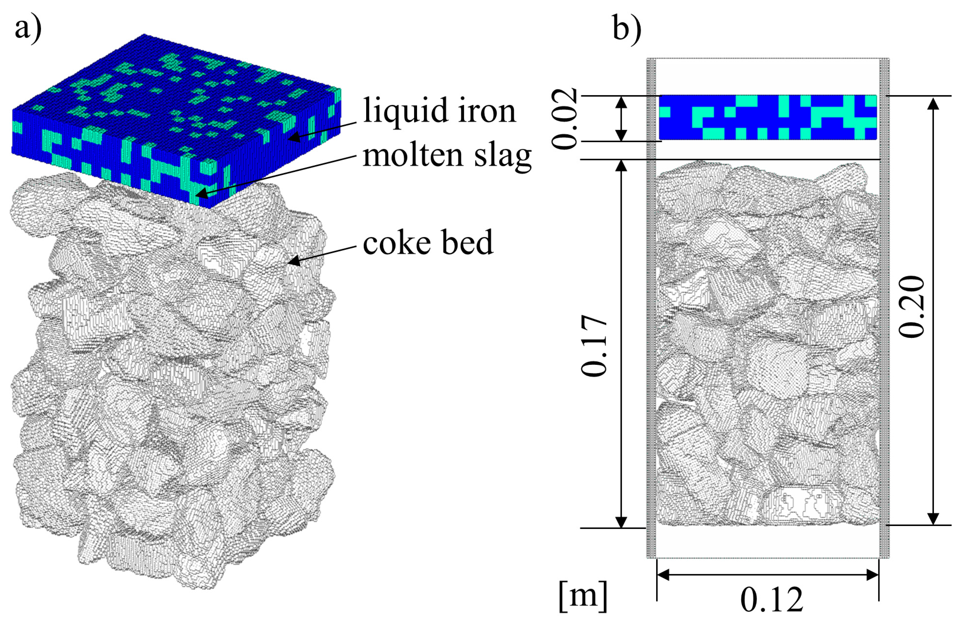
Detailed packed-bed-structure digital data consisting of multiple coke samples was constructed to simulate the lower part of the blast furnace. Assuming that the coke distribution was just above the raceway, representative coke samples with an average equivalent spherical volume diameter D = 0.0247 m was selected [42]. By using a three-dimensional scanning technique [26], 100 pieces of representative coke three-dimensional surface shape dataset were numerically obtained. About 300,000 surface points on each coke sample were obtained with a minimum resolution of 0.43 mm. The obtained coordinates were converted to standard triangulated language, and the surface shape was polygonal with a triangular mesh. The natural packed structure comprising these particles can be obtained by a DEM-based scheme. The basic format of the DEM is to track spherical particles. Multi-sphere (MS) DEM is a method utilizing a DEM contact force model that is expanded to handle the motion of freely shaped solids. It arrays spherical particles and expresses complex shapes to enable intuitive mounting. The position and rotation angles of each coke sample were determined by using a pseudorandom number, and the packed bed structure was determined by the MS-DEM simulation of a box-type container with 0.12-m sides, similar as a previous report [43]. Next, two immiscible liquids with a 0.12-m width and 0.02-m height were placed immediately above the packed bed to simulate the liquid iron-molten-slag trickle flow in the coke-packed bed. Position of liquid iron and molten slag was determined by using a pseudorandom number. The volume ratio was set as 8:2 to achieve the conditions similar to that of the actual operation. In SPH simulations for multi-phase flow that include a gas, the pressure differential becomes large between liquid and gas, and, consequently, the pressure gradient becomes excessive, thus making convergent calculation difficult. Therefore, in this research, a gas phase is assumed to exist in spaces where particles do not exist. The calculation domain is depicted in Figure 2. The well-known Courant–Friedrichs–Lewy condition was applied to determine dt. In this study, a calculation particle diameter dp of 1.00 mm was adopted as a constant value in all calculation processes. Thus, the following values were determined: d t = 1.0 × 10 5 s, the analysis time is 10 s, and the number of total particles is 1,402,280. All the programs were coded by the author. Each computer code was written in Fortran 90/95 and compiled and executed by an Intel Fortran compiler on a Windows system. The CPU used in this work was Intel Core i7-7820 × (3.6 GHz, 8 cores). A basic parallelized algorithm was applied using a multi-core processor and OpenMP. Simulation time was 1 week or more.

3. Results

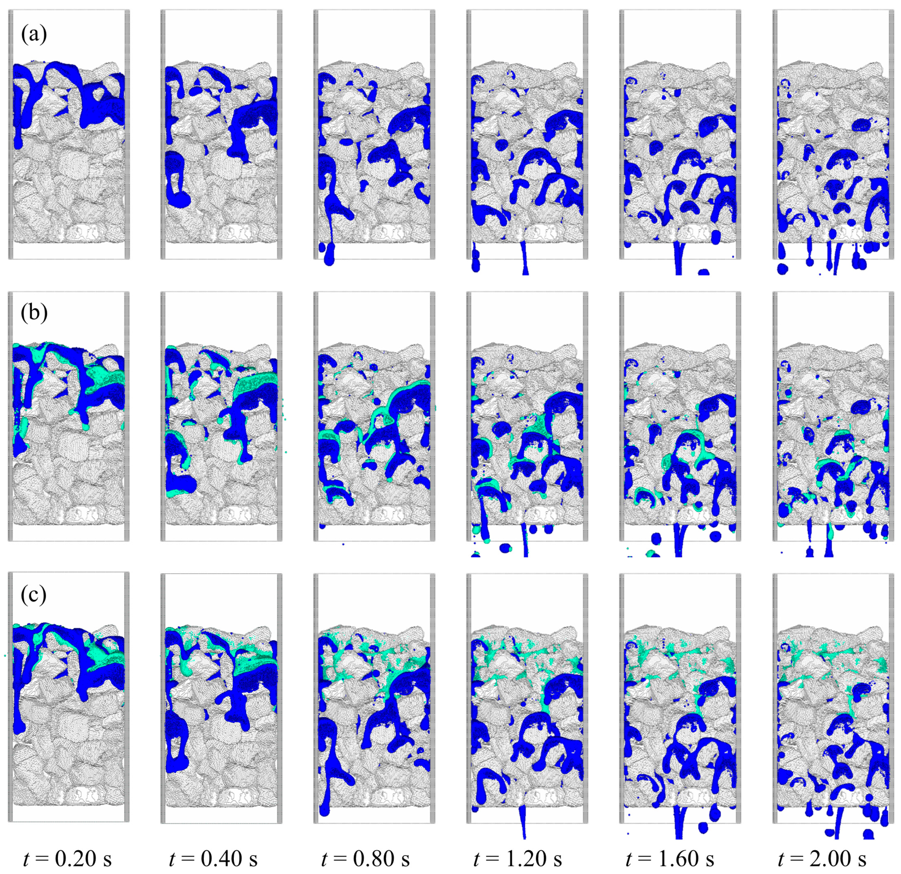
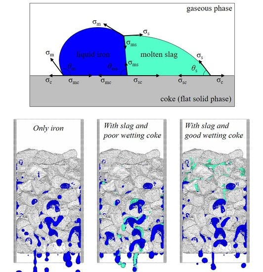
Figure 3 shows the temporal change in the three-dimensional distributions of the liquid iron (blue color) and molten slag (green color) as a result of the model calculation. The packed bed structure formed by irregularly shaped cokes is geometrically complex, and the liquid iron flow through the continuous void drops in the form of strings or droplets. From the viewpoint of localized flow behavior, several regions do not receive any flow, and it is assumed that liquid iron flows only through the limited region. However, the flow behavior of liquid iron is influenced by the presence of slag with different coke wettability, as shown in Figure 3b,c. As shown in Figure 3b, for a coke surface with poor wettability containing molten slag, the molten slag drops along with the liquid iron. However, the coke surface with good wettability shown in Figure 3c retains molten slag at the upper part of the packed bed owing to a high attractive force acting against the molten slag.
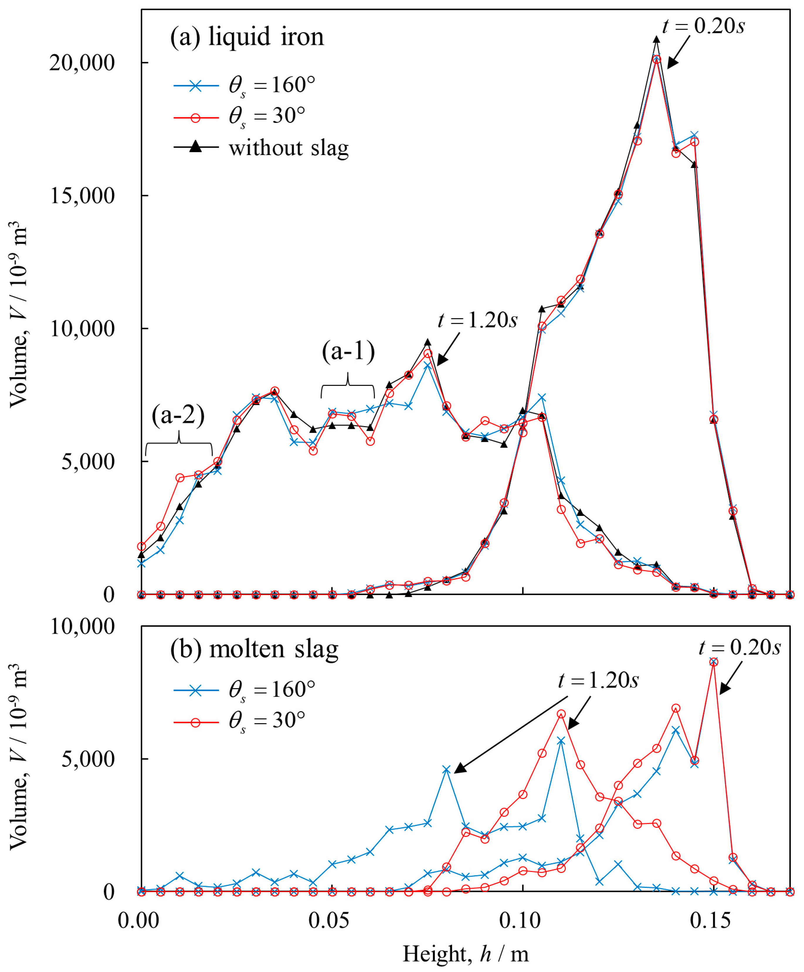
Figure 4 shows the volume distribution of liquid iron and molten slag in the height direction at t = 0.20 and 1.20 s. In Figure 4a, liquid iron almost has the same distribution at t = 0.20 s, irrespective of the presence of slag and the change in θs. Conversely, at t = 1.20 s, the liquid iron with slag exists at a lower height compared to “without slag” iron. In the region shown in (a-1), liquid iron is concentrated regardless of θs, and in the region shown in (a-2), liquid iron is concentrated when θs = 30°. In Figure 4b, molten slag exists at a lower height when θs = 160° than that at 30°. The attractive force due to the wettability of the coke surface prevents slag from dripping in the direction of gravity. This change in wettability affects the flow form of the liquid iron shown in (a-1) and (a-2). It is necessary to determine the time change of each melt velocity to consider the dripping mechanism leading to this result. The average velocity in the gravitational direction per unit time is given, considering the temporal change in the center of gravity of each phase, as follows [44]:
v z = 1 V Δ t ( r i , t + Δ t r i , t ) d V
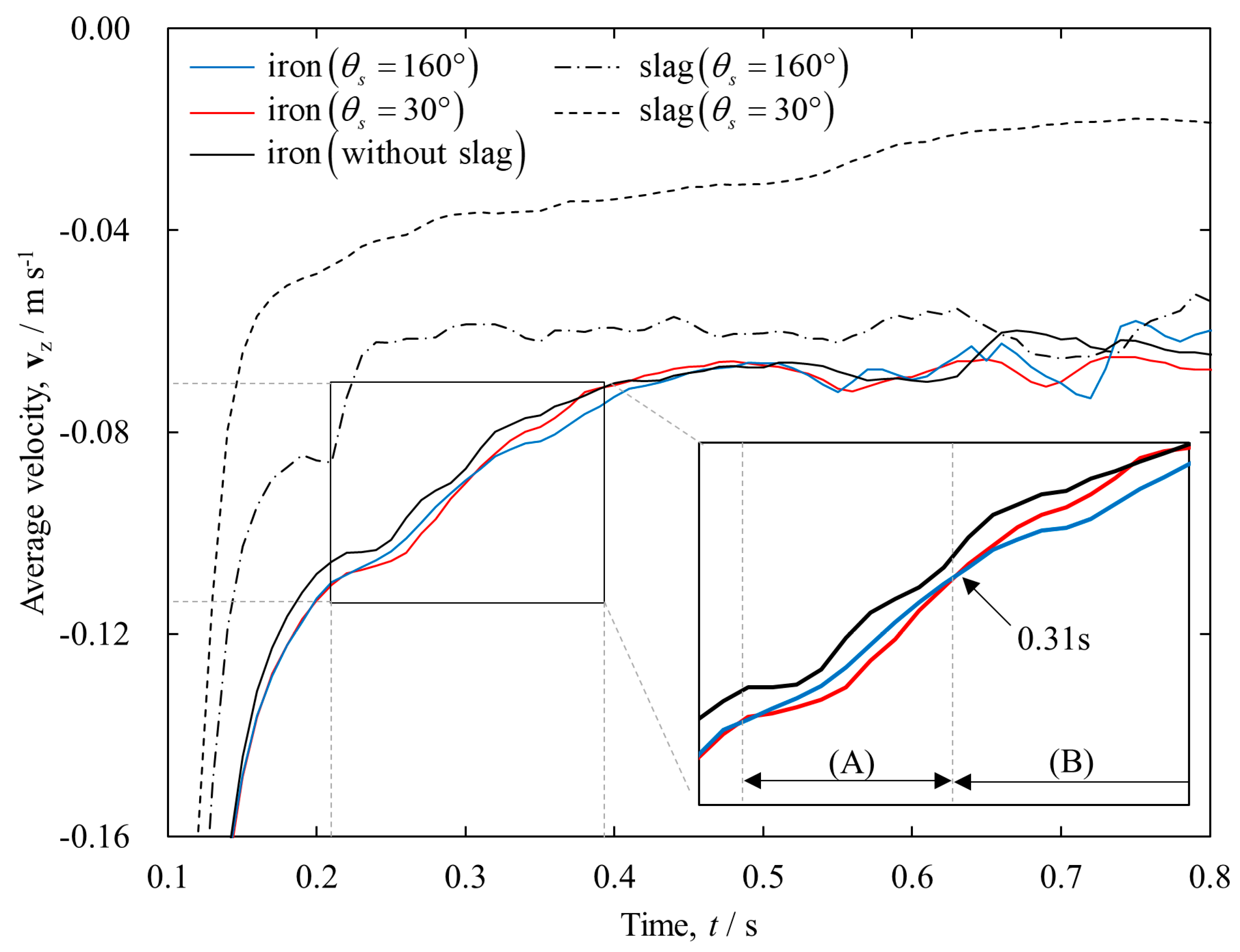
Figure 5 displays the average velocity of each melt. At t > 0.5 s, the liquid iron almost reaches a steady state and almost corresponds to the flow at the lower part of the blast furnace presented by Sugiyama et al. [45] and also appears to follow the Darcy-type equation. From a detailed perspective, however, the liquid iron tends to increase the dripping rate because of the presence of slag. Moreover, the velocity of liquid iron is affected by the wettability between the slag and coke. The angle θs = 30° yields the maximum liquid-iron velocity within range (A); in contrast, θs = 160° represents the maximum velocity in region (B). This reversal occurs at t = 0.31 s. As observed from Figure 4, the liquid iron dripping rate is higher than that of molten slag. Due to the difference in density between the two melts, the gravitational force of liquid iron was 2.7 times higher than that of molten slag. As molten slag has a high viscosity and low density, it appears that it prevents liquid iron from descending. However, when θs = 30°, the coke bed surface is wet by slag immediately and facilitates the sliding of the liquid iron. With time, this “lubrication” by molten slag is lost, because the liquid iron moves below the molten slag. When θs = 160°, the effect of wetting becomes weak, and the molten slag drips along with the liquid iron. Thus, the “lubrication” between the molten slag and liquid iron remains on the coke surface. Since the molten slag drops slowly, owing to the 0.37 times density and 53 times viscosity coefficient of the liquid iron, these observations appear as slight differences.
The variation in the wettability between the coke and molten slag modifies the interfacial area between the four-phase iron-slag-coke-gas by the following mechanism. When some droplets are dispersed in the system under isothermal conditions, the Helmholtz free energy, F = σ i j A i , of the system increases. Since the potential energy corresponding to the flow of the liquid iron droplets through the packed bed is equal for each case, the kinetic energy corresponding to the secondary droplet formation may be the same for all the conditions. However, the total energy in the system is not conserved due to the viscous damping from this calculation, but it is useful to clarify the effect of wettability between the coke and slag on the interfacial area of each phase. As our interest is focused on the effect of wettability between the slag and coke on the interfacial energy of each phase, the interfacial area for each phase should be estimated. The main advantage of the SPH method is its rapid prediction of the interface area A from its initial condition A 0 and the interface-judged particle number n .
A ( t ) n ( t ) n 0 A 0
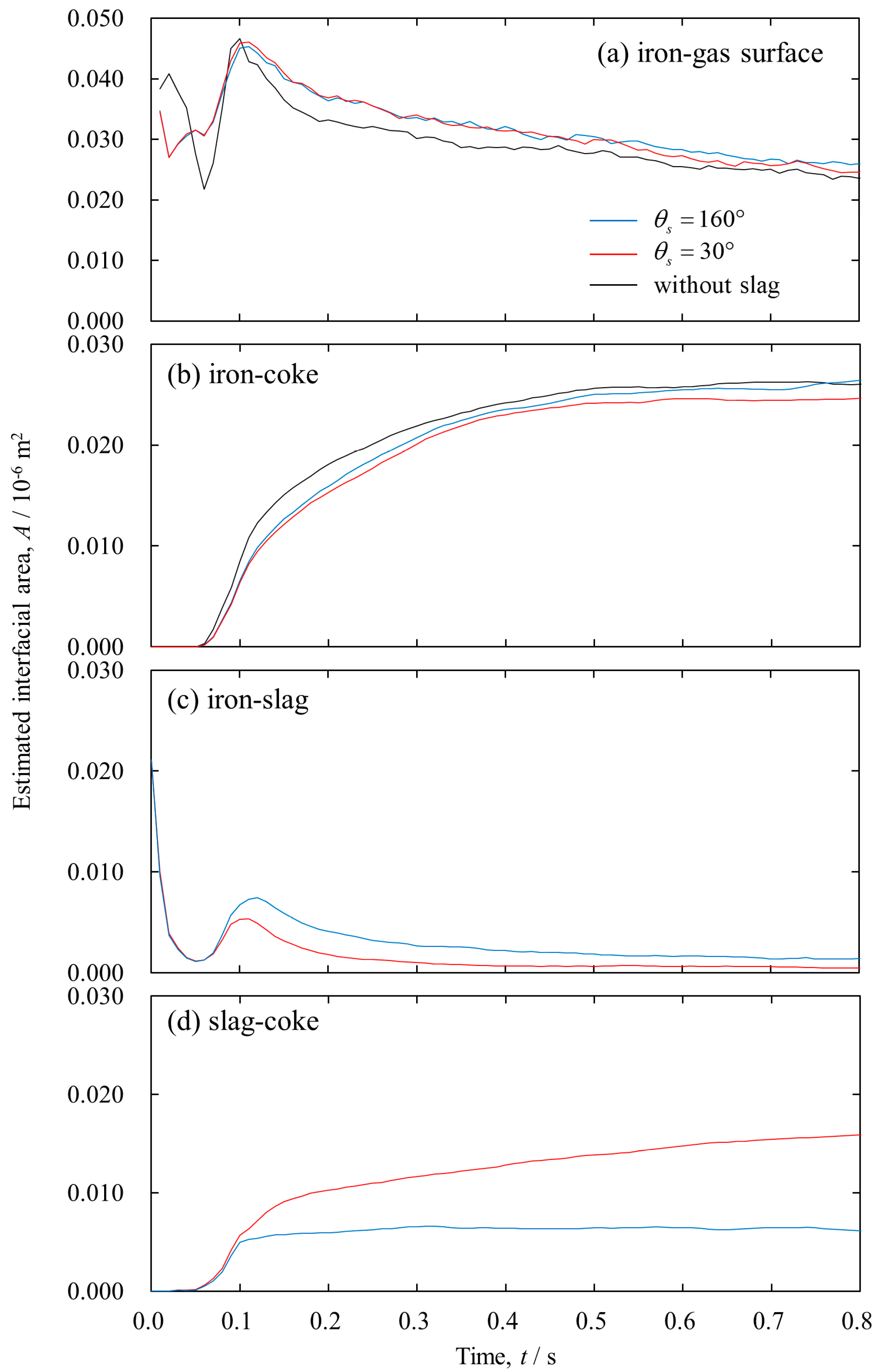
A 0 is geometrically determined from the initial conditions. In this study, the free surface of the liquid iron and slag are 0.04992 and 0.01248 m2, respectively, and the initial iron-slag interface area is 0.02110 m2. See Section 2 and a previous report [46] for the counting procedure of n. Figure 6 depicts the time change of the estimated interfacial area of each phase. At t = 0.1 s, the melt penetrates the coke bed, and both interfacial areas significantly vary simultaneously. In Figure 6a, for “without slag” liquid iron, the initial iron-gas surface area is significantly different from that of “with slag”, but the area becomes almost equal to other conditions at t = 0.1 s. The case of θs = 160° sometimes indicates a larger iron-gas surface area than that of “without slag”, because the iron slides down first and forms a contact interface at a lower height. Beyond t = 0.1 s, “without slag” iron has the lowest iron-gas surface area. This behavior can be explained as follows. As shown in Figure 6b, since the liquid is not affected by molten slag in “without slag” liquid iron, the iron-coke interfacial area significantly increases compared to that of “with slag” at t > 0.1 s; in other words, the iron-coke interface decreases with the presence of the molten slag. From Figure 6c, although the iron-slag interface area has a larger value at θs = 160° than at θs = 30°, the slag-coke interface area exhibits the opposite trend, as observed in Figure 6d. Since the coke surface with good wettability is covered with slag, it will likely increase the contact area between the free surface of the slag and iron-slag in a static state. In the case of θs = 160°, the slag drops with the liquid iron due to gravity. This dripping occurs because the attractive force acting between the coke and slag is less than the gravitational force. However, for θs = 30°, the attractive force acting between the coke-slag interface dominates, and the iron-slag interface is preferentially detached. Here, the effect of momentum in the direction of gravity appears. Since a “quasi-stable” interface is formed by the balance between the melt momentum and the force acting on each interface, the state predicted by the equilibrium theory is not always achieved during dripping [47]. This result indicates that static hold-up of the molten slag may promote the smooth dripping of liquid iron, as variations in the wettability between the coke and slag transiently change the flow field of the liquid iron. It emphasizes the distinctive interfacial features that can depend on interactions with the wettability of nonuniform packed cokes and the transient behavior of two melts. In the future, the calculation region of this model can be expanded and the model may be applied to continuous dripping, and the application of the model can also be extended to the entire bottom of the blast furnace.

4. Conclusions

Numerical simulations using a multi-phase SPH method were performed on two immiscible high-temperature melts dripping through a coke-packed bed during an ironmaking blast furnace process, namely, a binary trickle flow in which liquid iron and molten slag dripped simultaneously. The advantage of this method is the direct estimation of the transient three-dimensional behavior of multi-phase flow based on body forces considering the force acting between different phases, including complex dispersed phases. The present detailed analysis helps in the rationalization of the unexplained transient behavior of liquid iron and molten slag presented by previous experiments. In particular, the effect of coke surface wettability for molten slag on binary trickle flow was investigated.
The flow behavior of liquid iron is influenced by the presence of slag in coke surfaces with different coke wettability. If the coke surface has poor wettability and contains molten slag, the molten slag drops along the molten iron. However, a coke surface with good wettability retains molten slag owing to a higher attractive force acting between the coke and slag rather than an interfacial force of attraction acting between the iron and slag. Although the molten slag dripping rate is lower than that of the liquid iron because of high viscosity and low density, the coke bed surface is wet by slag immediately and facilitates the sliding of the liquid iron. These results demonstrate that the static hold-up of molten slag may promote the smooth dripping of liquid iron. As predicted by novel findings presented in this study, when the low reducing agent ratio operation is realized, increases in the amount of liquid iron and molten slag passing through a unit volume of coke bed finally influence the amount of stagnant melt behavior in the coke bed through a mechanism in which the descent velocity of each melt depends on coke-slag wettability. Through this analysis, the mechanism underlying the simultaneous trickle flow of liquid iron-molten slag behaviors, as described in conventional research, can be explained from a unified point of view.

Author Contributions

Data curation, S.N., H.N., T.K. (Tatsuya Kikuchi), S.I., and S.U.; funding acquisition, S.N. and K.-i.O.; investigation, K.-i.O. and S.S.; methodology, S.N. and T.K. (Tatsuya Kon); software, S.N. and T.K. (Tatsuya Kon); validation, T.K. (Tatsuya Kon); visualization, T.K. (Tatsuya Kon); writing—original draft, S.N.; and writing—review and editing, S.N., H.N., K.T. and R.O.S. All authors have read and agreed to the published version of the manuscript.

Funding

This study was funded by the Steel Foundation for Environmental Protection Technology (SEPT), Japan, grant number C-41-52, and supported by the Japan Society for the Promotion of Science (JSPS) KAKENHI, grant number 15H04168.

Acknowledgments

The authors thank Shinsuke Taya, Kentaro Baba, Azuma Hirai, Akihisa Ito, and Miho Hayasaka for their support with the construction of the computing environment at Tohoku University, IMRAM.

Conflicts of Interest

The authors declare no conflict of interest.

References

  1. Fukutake, T.; Rajakumar, V. Liquid holdups and abnormal flow phenomena of the gas-liquid counter-current flow in packed beds under simulating conditions of the flow in the dropping zone of a blast furnace. Tetsu-to-Hagané 1980, 66, 1937–1946. [Google Scholar] [CrossRef] [Green Version]
  2. Chew, S.J.; Zulli, P.; Yu, A. Modelling of liquid flow in the blast furnace. Application in a comprehensive blast furnace model. ISIJ Int. 2001, 41, 1122–1130. [Google Scholar] [CrossRef]
  3. Kawabata, H.; Shinmyou, K.; Harada, T.; Usui, T. Influence of channeling factor on liquid hold-ups in an initially unsoaked bed. ISIJ Int. 2005, 45, 1474–1481. [Google Scholar] [CrossRef] [Green Version]
  4. Husslage, W.M.; Bakker, T.; Steeghs, A.G.S.; Reuter, M.A.; Heerema, R.H. Flow of molten slag and iron at 1500 °C to 1600 °C through packed coke beds. Metall. Mater. Trans. B 2005, 36, 765–776. [Google Scholar] [CrossRef]
  5. Jang, D.; Shin, M.; Oh, J.S.; Kim, H.S.; Yi, S.H.; Lee, J. Static holdup of liquid slag in carbonaceous beds. ISIJ Int. 2014, 54, 1251–1255. [Google Scholar] [CrossRef] [Green Version]
  6. Wang, G.; Liu, Y.; Zhou, Z.; Wang, J.; Xue, Q. Static holdup of liquid slag in simulated packed coke bed under oxygen blast furnace ironmaking conditions. JOM 2018, 70, 29–33. [Google Scholar] [CrossRef]
  7. Ohgusu, H.; Sassa, Y.; Tomita, Y.; Tanaka, K.; Hasegawa, M. Main factors affecting static holdup of molten slag in coke-packed bed. Tetsu-to-Hagané 1992, 78, 1164–1170. [Google Scholar] [CrossRef] [Green Version]
  8. Oh, J.S.; Lee, J. Composition-dependent reactive wetting of molten slag on coke substrates. J. Mater. Sci. 2016, 51, 1813–1819. [Google Scholar] [CrossRef]
  9. White, J.F.; Lee, J.; Hessling, O.; Glaser, B. Reactions between liquid CaO-SiO2 slags and graphite substrates. Metall. Mater. Trans. B 2017, 48, 506–515. [Google Scholar] [CrossRef] [Green Version]
  10. Saito, K.; Ohno, K.I.; Miki, T.; Sasaki, Y.; Hino, M. Behavior of ironmaking slag permeation to carbonaceous material layer. ISIJ Int. 2006, 46, 1783–1790. [Google Scholar] [CrossRef] [Green Version]
  11. Kang, T.W.; Gupta, S.; Saha-Chaudhury, N.; Sahajwalla, V. Wetting and interfacial reaction investigations of coke/slag systems and associated liquid permeability of blast furnaces. ISIJ Int. 2005, 45, 1526–1535. [Google Scholar] [CrossRef] [Green Version]
  12. Geleta, D.D.; Siddiqui, M.I.H.; Lee, J. Characterization of Slag Flow in Fixed Packed Bed of Coke Particles. Metall. Mater. Trans. B 2019. [Google Scholar] [CrossRef]
  13. Vångö, M.; Pirker, S.; Lichtenegger, T. Unresolved CFD-DEM modeling of multiphase flow in densely packed particle beds. Appl. Math. Model. 2018, 56, 501–516. [Google Scholar] [CrossRef]
  14. Jiao, L.; Kuang, S.; Yu, A.; Li, Y.; Mao, X.; Xu, H. Three-dimensional modeling of an ironmaking blast furnace with a layered cohesive zone. Metall. Mater. Trans. B 2020, 51, 258–275. [Google Scholar] [CrossRef]
  15. Rabbani, H.S.; Joekar-Niasar, V.; Pak, T.; Shokri, N. New insights on the complex dynamics of two-phase flow in porous media under intermediate-wet conditions. Sci. Rep. 2017, 7, 4584. [Google Scholar] [CrossRef] [PubMed]
  16. Rabbani, H.S.; Or, D.; Liu, Y.; Lai, C.Y.; Lu, N.B.; Datta, S.S.; Stone, H.A.; Shokri, N. Suppressing viscous fingering in structured porous media. Proc. Natl. Acad. Sci. USA 2018, 115, 4833–4838. [Google Scholar] [CrossRef] [Green Version]
  17. Natsui, S.; Ishihara, S.; Kon, T.; Ohno, K.; Nogami, H. Detailed Modelling of Packed-bed Gas Clogging Due to Thermal-softening of Iron Ore by Eulerian-Lagrangian Approach. Chem. Eng. J. in press. [CrossRef]
  18. Alpak, F.O.; Berg, S.; Zacharoudiou, I. Prediction of fluid topology and relative permeability in imbibition in sandstone rock by direct numerical simulation. Adv. Water Resour. 2018, 122, 49–59. [Google Scholar] [CrossRef]
  19. Tartakovsky, A.M.; Panchenko, A. Pairwise force smoothed particle hydrodynamics model for multiphase flow: Surface tension and contact line dynamics. J. Comput. Phys. 2016, 305, 1119–1146. [Google Scholar] [CrossRef] [Green Version]
  20. Shao, L.; Saxén, H. A simulation study of two-liquid flow in the taphole of the blast furnace. ISIJ Int. 2013, 53, 988–994. [Google Scholar] [CrossRef] [Green Version]
  21. Kim, H.S.; Kim, J.G.; Sasaki, Y. The role of molten slag in iron melting process for the direct contact carburization: Wetting and separation. ISIJ Int. 2010, 50, 1099–1106. [Google Scholar] [CrossRef] [Green Version]
  22. Jeong, I.H.; Kim, H.S.; Sasaki, Y. Trickle flow behaviors of liquid iron and molten slag in the lower part of blast furnace. ISIJ Int. 2013, 53, 2090–2098. [Google Scholar] [CrossRef] [Green Version]
  23. Ghosh, S.; Viswanathan, N.N.; Ballal, N.B. Flow phenomena in the dripping zone of blast furnace—A review. Steel Res. Int. 2017, 88, 1600440. [Google Scholar] [CrossRef]
  24. Kon, T.; Natsui, S.; Ueda, S.; Nogami, H. Analysis of effect of packed bed structure on liquid flow in packed bed using moving particle semi-implicit method. ISIJ Int. 2015, 55, 1284–1290. [Google Scholar] [CrossRef] [Green Version]
  25. Natsui, S.; Kikuchi, T.; Suzuki, R.O.; Kon, T.; Ueda, S.; Nogami, H. Characterization of liquid trickle flow in poor-wetting packed bed. ISIJ Int. 2015, 55, 1259–1266. [Google Scholar] [CrossRef] [Green Version]
  26. Natsui, S.; Nashimoto, R.; Takai, H.; Kumagai, T.; Kikuchi, T.; Suzuki, R.O. SPH simulations of the behavior of the interface between two immiscible liquid stirred by the movement of a gas bubble. Chem. Eng. Sci. 2016, 141, 342–355. [Google Scholar] [CrossRef]
  27. Natsui, S.; Sawada, A.; Kikuchi, T.; Suzuki, R.O. Holdup characteristics of melt in coke beds of different shapes. ISIJ Int. 2018, 58, 1742–1744. [Google Scholar] [CrossRef] [Green Version]
  28. Natsui, S.; Nashimoto, R.; Kikuchi, T.; Suzuki, R.O.; Takai, H.; Ohno, K.; Sukenaga, S. Capturing the non-spherical shape of granular media and its trickle flow characteristics using fully-Lagrangian method. AIChE J. 2017, 63, 2257–2271. [Google Scholar] [CrossRef]
  29. Nakano, M.; Ito, K. Three dimensional simulation of lime particle penetration into molten iron bath using smoothed particle hydrodynamics. ISIJ Int. 2016, 56, 1537–1542. [Google Scholar] [CrossRef] [Green Version]
  30. Tsuboi, M.; Ito, K. Cold model experiment and numerical simulation of flow characteristics of multi-phase slag. ISIJ Int. 2017, 57, 1191–1196. [Google Scholar] [CrossRef] [Green Version]
  31. Hosono, N.; Karato, S.I.; Makino, J.; Saitoh, T.R. Terrestrial magma ocean origin of the moon. Nat. Geosci. 2019, 12, 418–423. [Google Scholar] [CrossRef]
  32. Wendland, H. Piecewise polynomial, positive definite and compactly supported radial functions of minimal degree. Adv. Comput. Math. 1995, 4, 389–396. [Google Scholar] [CrossRef]
  33. Colagrossi, A.; Landrini, M. Numerical simulation of interfacial flows by smoothed particle hydrodynamics. J. Comput. Phys. 2003, 191, 448–475. [Google Scholar] [CrossRef]
  34. Lancaster, P.; Salkauskas, K. Surfaces generated by moving least squares methods. Math. Comput. 1981, 37, 141–158. [Google Scholar] [CrossRef]
  35. Monaghan, J.J. An introduction to SPH. Comput. Phys. Commun. 1988, 48, 89–96. [Google Scholar] [CrossRef]
  36. Kondo, M.; Koshizuka, S.; Suzuki, K.; Takimoto, M. Surface Tension Model Using Inter-particle Force in Particle Method. In Proceedings of the ASME/JSME 2007 5th Joint Fluids Engineering Conference, San Diego, CA, USA, 30 July 2007; American Society of Mechanical Engineers Digital Collection. pp. 93–98. [Google Scholar]
  37. Fowkes, F.M. Attractive forces at interfaces. Ind. Eng. Chem. 1964, 56, 40–52. [Google Scholar] [CrossRef]
  38. Keverian, J.; Taylor, H.F. Effects of gaseous and solid addition on surface tension and contact angle (on graphite) if various iron-carbon alloys. Trans. AFS 1957, 65, 212–221. [Google Scholar]
  39. Machin, J.S.; Yee, T.B. Viscosity studies of system CaO-MgO-Al2O3-SiO2: II, CaO-Al2O3-SiO2. J. Am. Ceram. Soc. 1948, 31, 200–204. [Google Scholar] [CrossRef]
  40. Mukai, K.; Ishikawa, T. Surface tension measurements on liquid slags in CaO-SiO2, CaO-Al2O3 and CaO-Al2O3-SiO2 systems by a pendant drop method. J. Jpn. Inst. Met. 1981, 45, 147. [Google Scholar] [CrossRef] [Green Version]
  41. Mehta, A.S.; Sahajwalla, V. Influence of composition of slag and carbonaceous materials on the wettability at the slag/carbon interface during pulverised coal injection in a blast furnace. Scand. J. Metall. 2000, 29, 17–29. [Google Scholar] [CrossRef]
  42. Watakabe, S.; Takeda, K.; Igawa, K. Coke properties and operational conditions of blast furnace to prevent coke degradation in the raceway. Tetsu-to-Hagané 2002, 88, 8–15. [Google Scholar] [CrossRef]
  43. Natsui, N.; Sawada, A.; Terui, T.; Kashihara, Y.; Kikuchi, T.; Suzuki, R.O. Evaluation of coke degradation effect on flow characteristics in packed bed using 3D scanning for rotational mechanical strength test and solid-liquid-gas three-phase dynamic model analysis. Tetsu-to-Hagané 2018, 104, 347–357. [Google Scholar] [CrossRef] [Green Version]
  44. Natsui, S.; Ohno, K.I.; Sukenaga, S.; Kikuchi, T.; Suzuki, R.O. Detailed modeling of melt dripping in coke bed by DEM-SPH. ISIJ Int. 2018, 58, 282–291. [Google Scholar] [CrossRef]
  45. Sugiyama, T.; Nakagawa, T.; Sibaike, H.; Oda, Y. Analysis on liquid flow in the dripping zone of blast furnace. Tetsu-to-Hagané 1987, 73, 2044–2051. [Google Scholar] [CrossRef]
  46. Natsui, S.; Nashimoto, R.; Kumagai, T.; Kikuchi, T.; Suzuki, R.O. An SPH study of molten matte–slag dispersion. Metall. Mater. Trans. B 2017, 48, 1792–1806. [Google Scholar] [CrossRef]
  47. Kon, T.; Sukenaga, S.; Ueda, S. Dynamic wettability of liquids on gasified metallurgical cokes. ISIJ Int. 2017, 57, 1166–1172. [Google Scholar] [CrossRef] [Green Version]
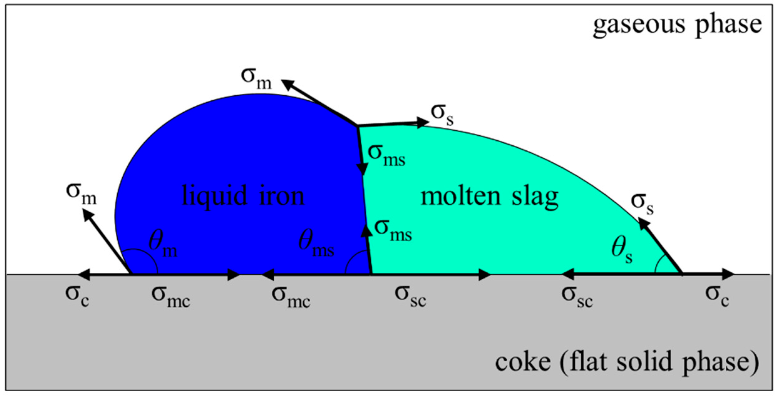
Figure 1. Two liquid droplets in contact on a flat, solid surface. These forces balance one another.
Processes 08 00221 g001
Figure 2. Schematic diagram of initial conditions: (a) three-dimensional view and (b) horizontal view of packed structure and liquid iron and molten slag.
Processes 08 00221 g002
Figure 3. Liquid iron and molten slag distributions on vertical cross-sections of a coke bed. (a) Without slag, (b) θs = 160°, and (c) θs = 30°.
Processes 08 00221 g003
Figure 4. Dripping profiles of liquid iron and molten slag. Calculation domain of coke bed was divided into 34 control volumes in the height direction (Δz = 0.005 m), and the profiles were derived by counting the number of liquid particles existing in each control volume as time passes.
Processes 08 00221 g004
Figure 5. Time variations in the mean dripping velocity. These profiles were obtained using a space integral by considering the center of gravity of all the droplets each time.
Processes 08 00221 g005
Figure 6. Time change of estimated interfacial area between each phase.
Processes 08 00221 g006