Article

Study on the Effect of Oxygen Concentration on the Properties of TiO2/Ti Composite Membranes Prepared by In Situ Oxidation

College of Petrochemical Technology, Lanzhou University of Technology, Lanzhou 730050, China
*
Author to whom correspondence should be addressed.
Processes 2020, 8(2), 213; https://doi.org/10.3390/pr8020213
Submission received: 14 January 2020 / Revised: 3 February 2020 / Accepted: 7 February 2020 / Published: 10 February 2020
(This article belongs to the Special Issue Nano-Hybrid Composite Membranes)

Abstract

:
TiO2 membranes were prepared on porous Ti supports through the in situ oxidation method. The effects of oxygen concentration, oxidation temperature, and oxidation time on the thickness, pore size, and microstructure of the prepared TiO2 membrane were investigated. The results showed that with increasing oxygen concentration, oxidation temperature, and oxidation time, the thickness of the prepared TiO2 membrane gradually increased, and the pore diameter gradually decreased. The optimum preparation conditions were—oxygen concentration was N2:O2 = 2:1, oxidation temperature was 800 ℃, and oxidation time was 60 min. The prepared TiO2/Ti composite membranes had a flat and smooth surface, uniform thickness, and only a rutile TiO2 characteristic peak formed on the surface of the membrane. The prepared TiO2/Ti composite membrane had a narrow pore size distribution, and the average pore size was about 0.312 μm. In addition, the prepared TiO2/Ti composite membranes showed an excellent stability.

1. Introduction

Ceramic–metallic composite membranes are composed of a porous ceramic separation membrane on porous metal support, which combines the advantages of porous metallic support and porous ceramic separation membrane [1,2,3]. Porous metal supports possess a higher pressure resistance, higher mechanical strength, and are easily fixed to a module by welding [4,5]. Porous ceramic membranes have high temperature stability, good chemical stability, a long life, and a stable pore structure [6,7]. Compared with Al2O3 and ZrO2 ceramic membrane, TiO2 ceramic membranes get more attention due to its better adhesive property, the lower sintering temperature, and some unique characteristics, such as catalysis, hydrophilicity, and semiconductivity [8,9,10].
Porous stainless steel (PSS) [11,12] has often been employed as metal support material for ceramic membrane, due to its excellent mechanical strength, ability to be fabricated into different shapes, and ease of welding or brazing. However, corrosion resistance, oxidation resistance, and high temperature resistance restrict their wide applications [13]. Recently, porous Ti material was proposed as a promising support for ceramic membranes based on many advantages, such as high specific surface area, low apparent specific gravity, and high penetration performance [14,15,16]. Lin et al. [17] prepared high-permeability TiO2 membrane on porous Ti support via the facile coating method, the prepared TiO2/Ti composite microfiltration (MF) membranes showed the most frequent pore size of 380 nm, and a high pure water permeability of 1150 L m−2h−1bar−1. Mao et al. [18] fabricated piezoelectric lead–zirconate–titanate (PZT)/Ti composite membranes by dry pressing PZT powder onto the porous Ti supports, followed by thermal processing. The combination of PZT membrane layer and porous Ti support appeared particularly suitable.
Many methods were used to prepare ceramic membrane on porous metal support, such as wet powder spraying, electrophoretic deposition, and screen printing [8,19,20]. All of the methods have its advantages, but these methods have several obvious shortcomings, such as a poor binding force between the ceramic layer and metal support, complex preparation processes, and harsh conditions. Therefore, there is an urgent need to develop novel methods to improve the binding force between the ceramic layer and the metal support. In situ oxidation method is an effective and a simple method to prepare an oxide ceramic layer on the surface of porous metal support, at high temperatures. Ma et al. [5] developed an in situ oxidation method for preparing intermediate diffusion barrier between the palladium and the PSS for the first time, which coated an oxide layer on the porous stainless steel supports through the in situ oxidation process, at high temperatures. Zhang et al. [21] prepared ceramic/Ti–Al alloy composite membranes through the in situ oxidation method, but they only studied the effect of the oxidation temperature on the microstructure and performance of the ceramic membrane. Atmospheric environment also had a great influence on the properties of the ceramic membranes in the sintering process [22,23].
In this work, the TiO2/Ti composite membranes were prepared through the in situ oxidation method. The effects of oxidation atmosphere, oxidation temperature, and oxidation time on the properties of the prepared TiO2/Ti composite membranes were investigated, and the optimum preparation conditions were determined, as well.

2. Experimental Method

2.1. Preparation of TiO2/Ti Composite Membranes

Preparation of TiO2/Ti composite membranes was carried out through the following two steps. First, the porous Ti support was put into a clean beaker and deionized water was added, then the ultrasonic device was turned on, the beaker was placed in the ultrasonic cleaner for 180 min under the heating condition, after that, samples were dried in the oven for 1440 min. Next, the above-mentioned porous Ti samples were put into the heating furnace to carry out the in situ oxidation experiment, according to the two-stage heating mode set by the program. The TiO2/Ti composite membranes were prepared by sintering the Ti discs in an atmospheric environment at temperatures ranging from 700 to 800 °C, in an electric furnace, with a heating and cooling rate of 6 °C/min, the atmospheric composition was set to N2:O2 = 2:1, N2:O2 = 1:1, and N2:O2 = 1:2, respectively. Finally, the samples were left to cool naturally.

2.2. Composite Membranes Characterization

The optimal in situ oxidation temperature of the Ti support was preliminarily determined by thermogravimetry (DTA-TG: DT-40, SHIMADZU, Kyoto, Japan). The gas flux change of N2 was tested through self-made laboratory membrane gas permeation devices [21]. Scanning electron microscopy (SEM: JSM6700F, Japan Electronics Corporation, Tokyo, Japan) was used to investigate the surface morphology and thickness of the TiO2 membrane. X-ray diffraction analysis (XRD: D/MAX-2400, Rigaku, Tokyo, Japan) was used to determine the compositional changes of the oxide layer on the surface of the support, under different conditions. The stability of the prepared TiO2/Ti composite membrane was investigated through ultrasonic treatment (KuDos, Shanghai Branch Super Co., Ltd., Shanghai, China).

3. Results and Discussion

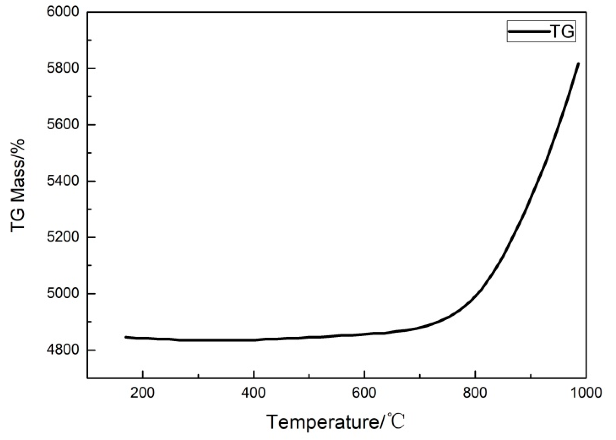
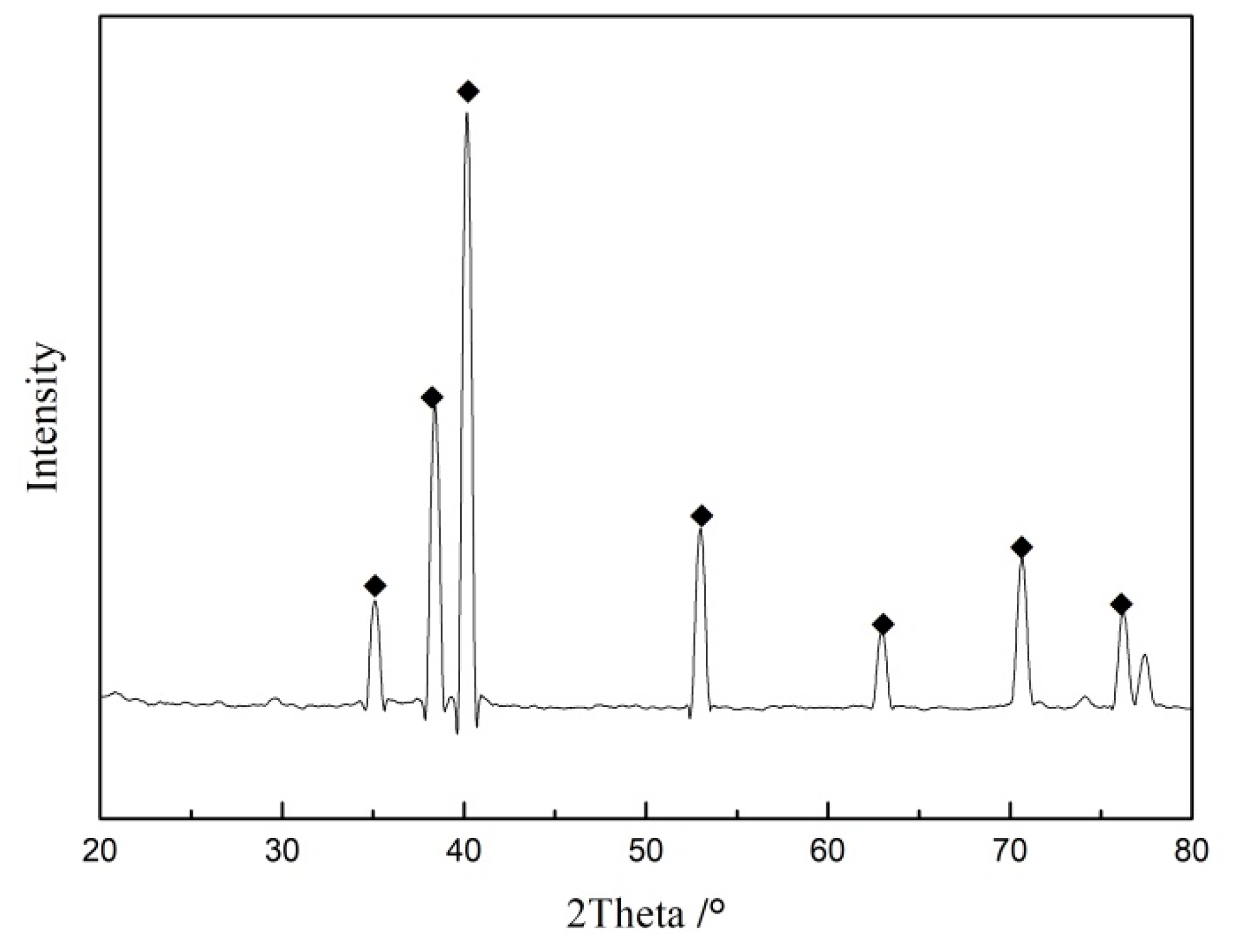
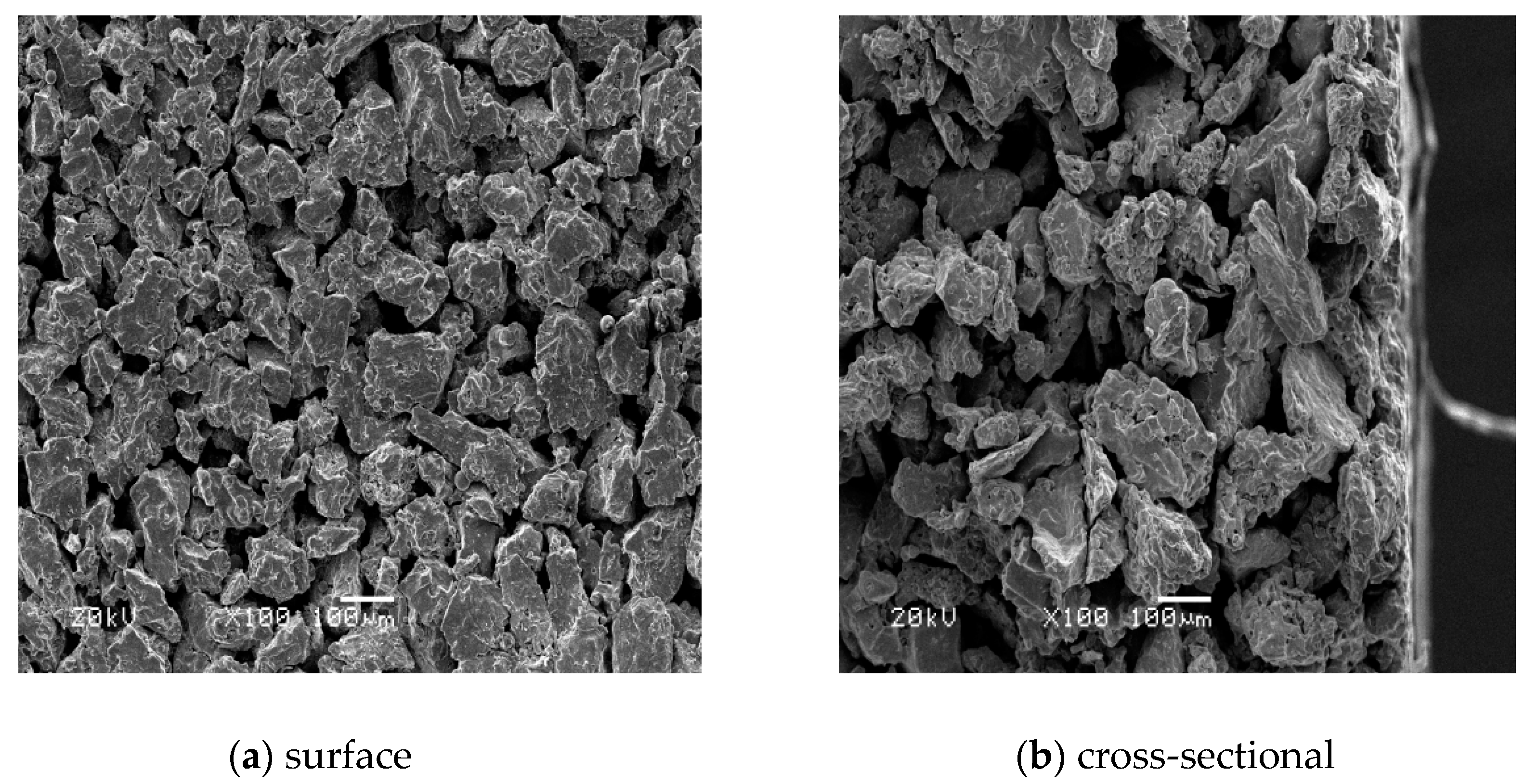
3.1. Characterization of the Porous Metal Ti Support

Figure 1 shows the surface and cross-section micromorphology of the porous Ti support. The surface of the support was relatively regular, and a continuous skeleton was formed between the Ti metal particles. The pore size distribution was relatively uniform, the average pore diameter was approximately 10−40 μm, and the defect diameter was about ~100 μm. It can be seen from the cross-sectional SEM image, that the support had an asymmetrical structure.
In order to determine the in situ oxidation temperature, the oxidation resistance of porous Ti support was investigated by the thermogravimetric method, which is shown in Figure 2. It was found that the mass of the support had a smaller change under an oxidation temperature below 700 °C, which indicated that the porous Ti metal support had a good oxidation resistance. When the oxidation temperature was higher than 800 °C, the sample began to oxidize at this temperature. While the oxidation temperature exceeded 850 °C, the mass of the sample increased sharply. Therefore, the in situ oxidation temperature of porous Ti support can then be determined between 700 °C and 850 °C, and the optimum oxidation temperature can be determined by studying the properties of the membranes prepared at different temperatures.
The phase composition of the porous metal Ti support before any treatment was analyzed by X-ray diffractometer; results are shown in Figure 3. The diffraction peak of the metal Ti indicated that the metal Ti (PDF: 05-0682) was the main component of the Ti support, which had good mechanical properties and high temperature stability.

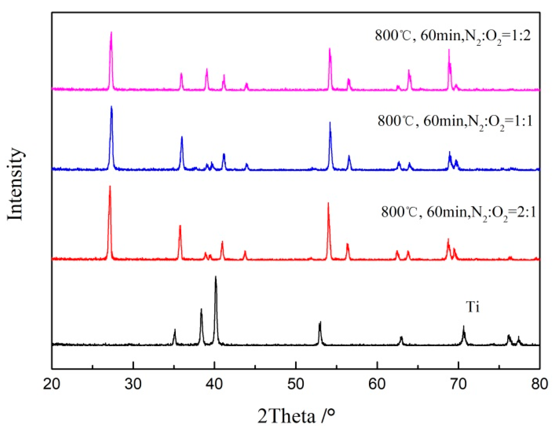
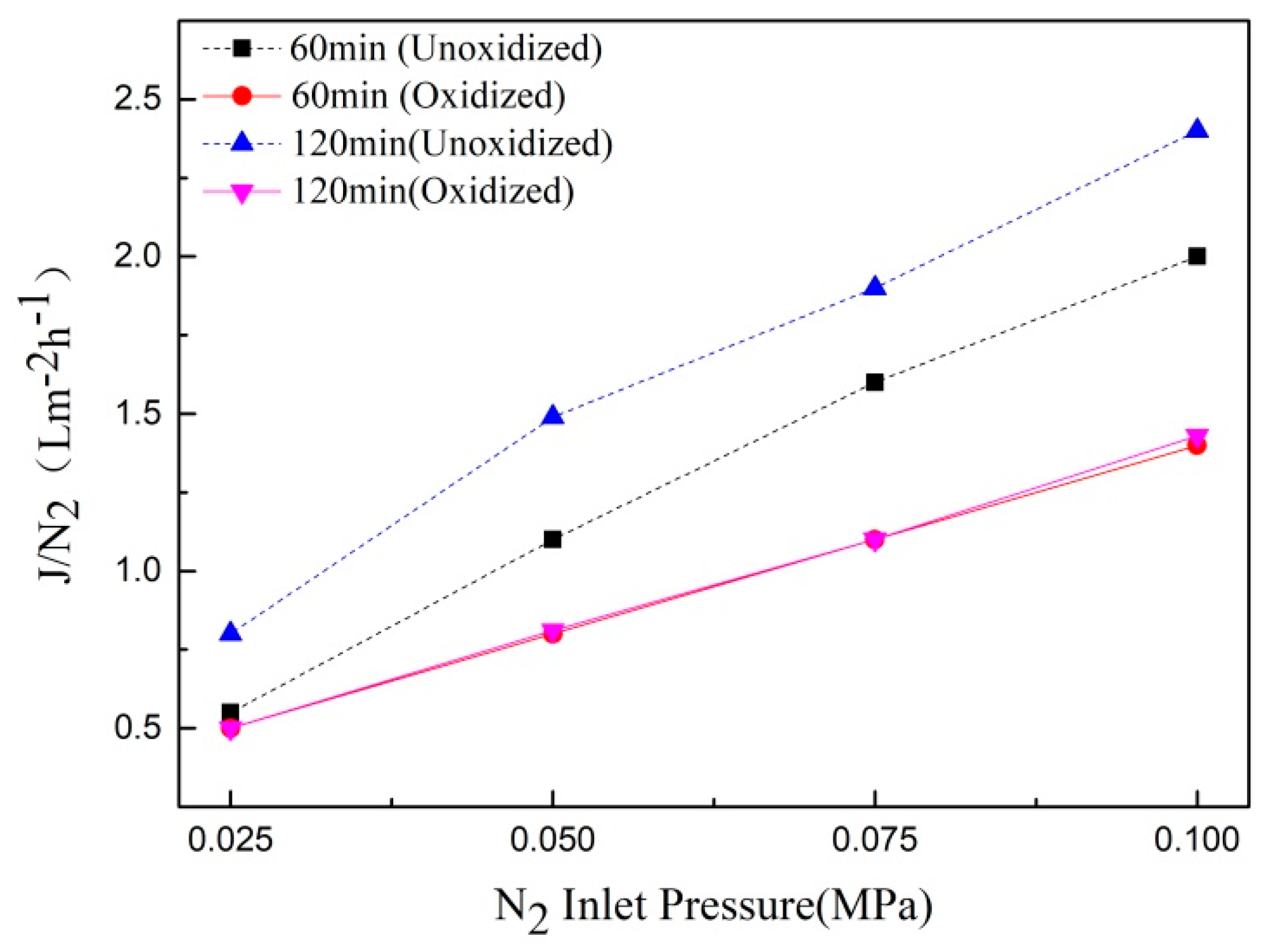
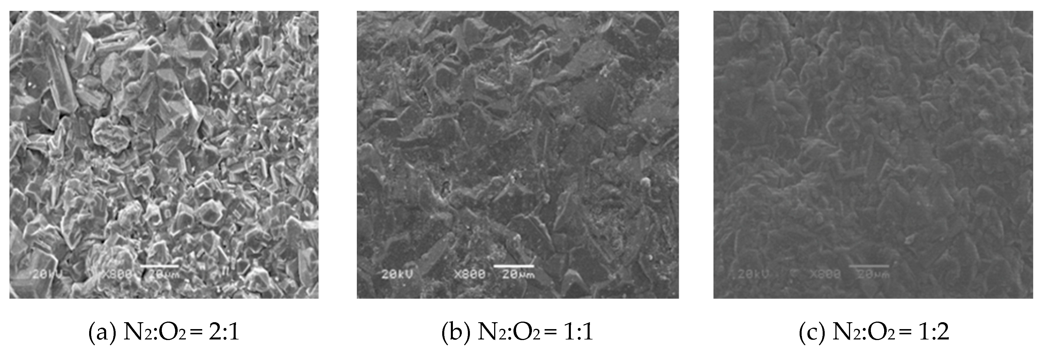
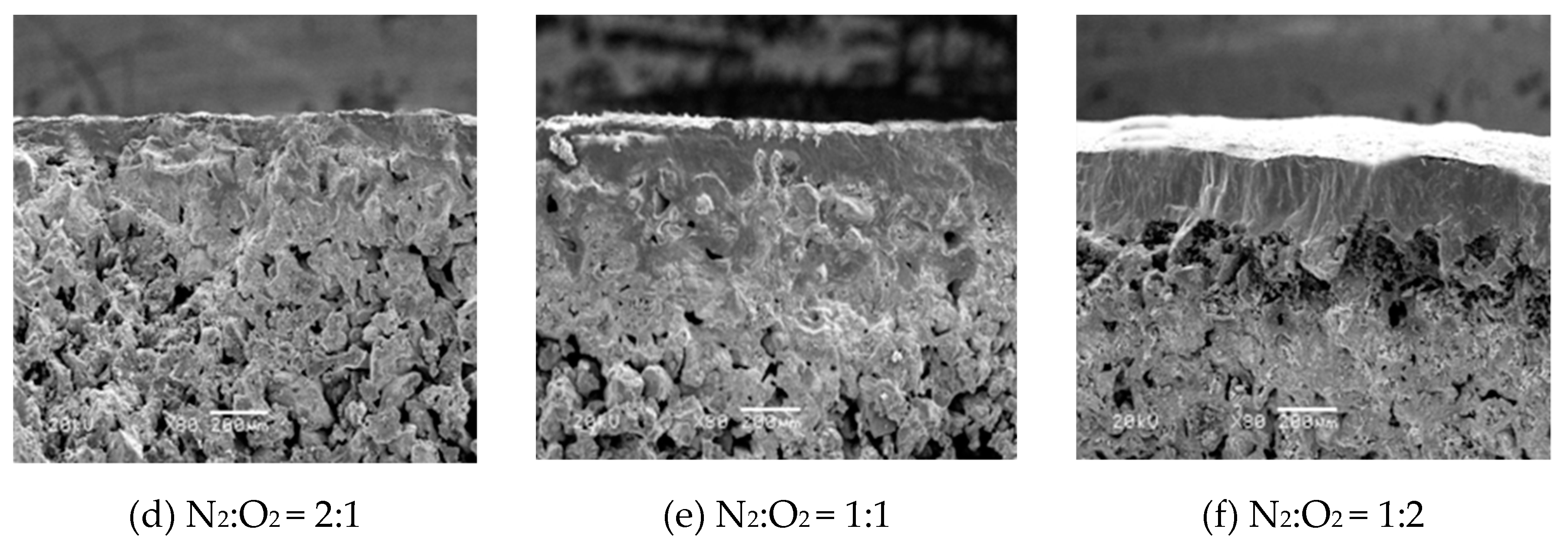
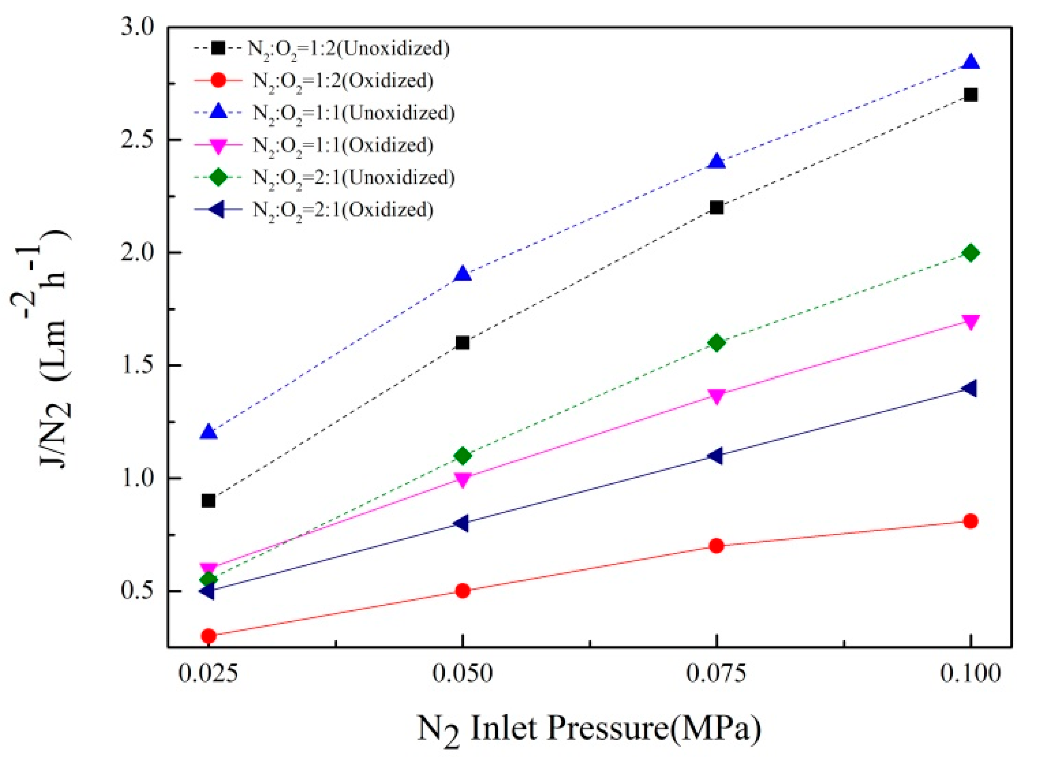
3.2. Effects of Oxygen Concentration on Properties of TiO2/Ti Composite Membranes

The effects of different oxygen concentrations on the properties of TiO2/Ti composite membranes were investigated at the oxidation temperature of 800 °C, for 60 min.
Figure 4 shows the surface and cross-section micromorphology of the TiO2/Ti composite membranes at different oxygen concentrations. As can be seen from the surface SEM figure, with the increase of oxygen concentration, the surface oxide layer gradually increased. When N2:O2 = 2:1, the surface of the Ti support changed significantly, and a continuous membrane layer was formed on the surface. When N2:O2 = 1:1, the surface of the Ti support was smoother and part of the surface became dense. When the N2:O2 = 1:2, the dense portion of the surface oxide layer continued to increase, which was an indication that the samples would probably present lower or no gas permeability. It can be seen from the cross-section SEM image, with an increase in oxygen concentration, the thickness of the oxide membrane gradually increased. When N2:O2 = 2:1, a continuous ceramic membrane layer was formed on the surface of the support, and the thickness was relatively uniform. The skeleton structure of the support section was still clearly visible, which could be attributed to the in situ oxidation that firstly occurred on the surface of the metal support or adjacent to the surface, the narrow pores further prevented the diffusion of oxygen molecules, so the support after the in situ oxidation still had a large gas permeability, good mechanical strength, and stability. When N2:O2 = 1:1, a thick membrane layer was formed on the surface of the support, and partial oxidation occurred inside the support near the membrane surface, which affected the performance of the composite membrane. When N2:O2 = 1:2, the thickness of the membrane continued to increase, and a large number of voids appeared between the oxide layer and the support, this was due to the increase in the oxidation rate when the oxygen concentration was high, which seriously affected the stability of the composite membrane.
The TiO2/Ti composite membranes after oxidation at 800 ℃ and different oxygen concentrations for 60 min were analyzed by X-ray diffraction (XRD); results are shown in Figure 5. It was found that the TiO2 peak of rutile (PDF: 21-1267) appeared on the surface of the support, and no characteristic peak of metal Ti was found, which was mainly due to the formation of more oxides on the surface of the support, at 800 °C. The results showed that a complete TiO2 oxide layer had formed on the surface of porous Ti support, under this condition.
The gas flux of TiO2/Ti composite membrane after in situ oxidation at 800 °C for 60 min was measured using a gas permeation device; the test results are shown in Figure 6. The N2 permeability of the composite membrane decreased gradually with the increase of oxygen concentration. This was because when the oxygen concentration was N2:O2 = 2:1, the oxide layer formed on the surface of the support was thin and there were small pores generated on the surface, which had little effect on the permeability of N2. With an increase in oxygen concentration, a dense oxide layer was formed on the surface and the thickness increased gradually, which seriously affected the gas permeability of the support. This was consistent with the results of SEM image analysis of the support.
After in situ oxidation, the composite membrane was boiled and cleaned by the ultrasonic method, and the mass change of the support, before and after oxidation was measured to characterize the stability of the TiO2/Ti composite membrane. The mass before oxidation was determined to be Mbefore /g, the mass after oxidation was determined to be Mafter/g, and the mass difference before and after oxidation was determined to be ΔM. The sample was taken out after boiling for 30 min, and subjected to ultrasonic cleaning treatment for 30 min, and then placed in a blast drying oven under 120 °C for 1440 min. The mass of the dried sample was determined as M1, 2, 3; repeating this process 3 times. Table 1 shows the quality change of the TiO2/Ti composite membrane, before and after ultrasonic cleaning.
The results indicated that there was a small increase in the composite membrane prepared at different oxygen concentrations after stability tests, meaning it had a good stability. Thus, the prepared TiO2/Ti composite membrane had an excellent stability.
In summary, the optimal oxygen concentration condition for preparing the TiO2/Ti composite membrane was N2:O2 = 2:1, under the condition of oxidation temperature of 800 °C and in situ oxidation time of 60 min.

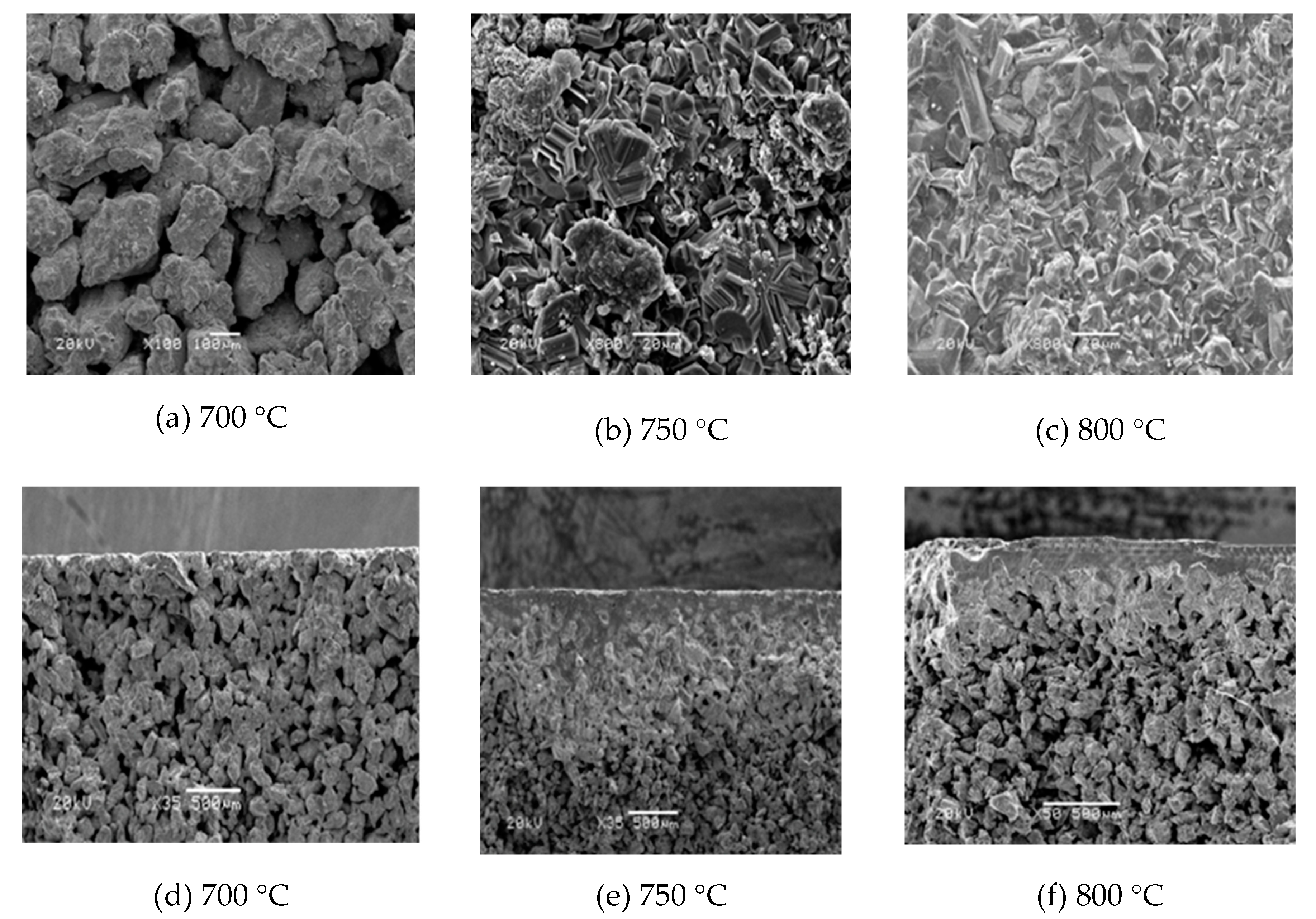
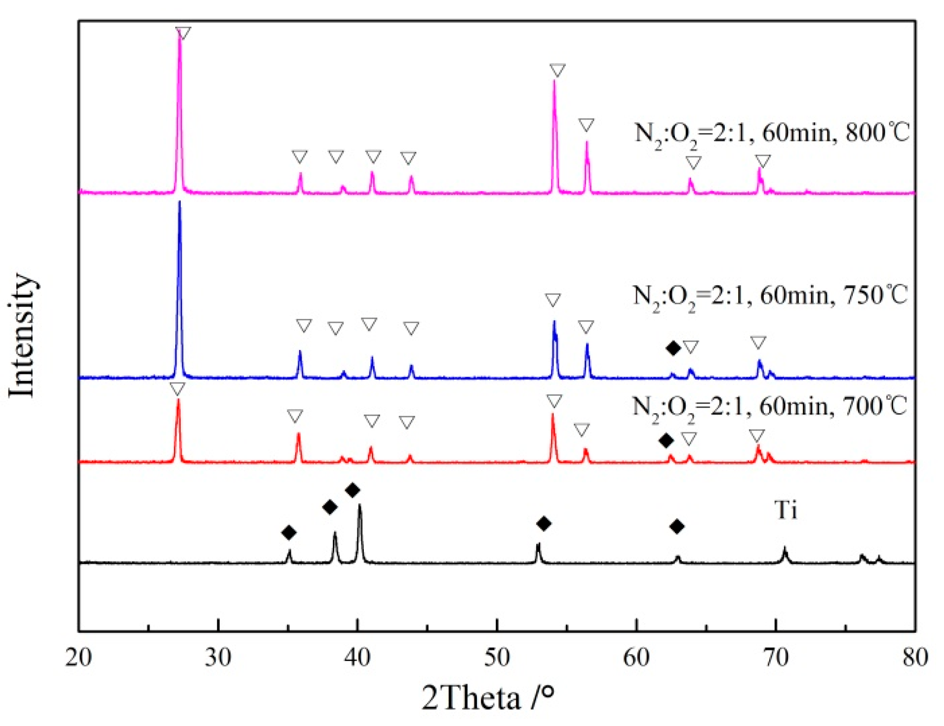
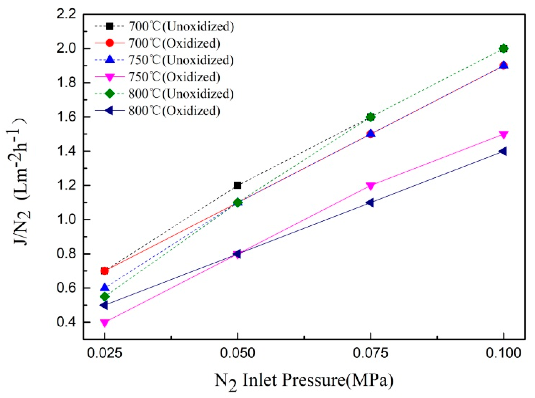
3.3. Effects of Oxidation Temperature on the Properties of TiO2/Ti Composite Membranes

The effects of different oxidation temperatures on the properties of TiO2/Ti composite membranes were investigated under the oxidation concentration of N2:O2 = 2:1 and oxidation time of 60 min.
Figure 7 shows the surface and cross-section SEM morphology of the composite membrane after in situ oxidation, under oxygen concentration N2:O2 = 2:1 for 60 min, at different temperatures. According to the surface SEM images, the surface morphology of the support after in situ oxidation treatment at 700 °C for 60 min was basically unchanged, compared to the original sample, indicating that the complete membrane layer was not formed, which was consistent with the results of thermogravimetric analysis. When the temperature rose to 750 °C, the surface oxide layer gradually increased, and the Ti particles began to bond together, and a layer was formed on the surface of the support. The SEM images at 800 °C showed that a continuous and smooth oxidized ceramic membrane was formed, and the pore size was modified at the same time. From the SEM image of the cross-section, it can be seen that the thickness of the oxide layer gradually increased as the in situ oxidation temperature increased. The skeleton structure of the support was visible clearly at 700 °C, and a thin layer of oxide layer appeared on the surface, which proved that no complete oxidation membrane was formed. A complete ceramic membrane was formed on the surface of the support at 750 °C and 800 °C, and it could be clearly seen that there was no change in the internal pores of the support, but the samples were only slightly oxidized in some areas near the oxide layer, indicating the oxide layer effectively prevented oxygen molecules entering into the pore of the support, so that the in situ oxidation mainly occurred on the surface of the support.
The TiO2/Ti composite membranes were analyzed through X-ray diffraction (XRD) under N2:O2 = 2:1 for 60 min, at different temperatures. As shown in Figure 8, compared to the XRD analysis results of porous Ti metal support, when the temperature was 700 °C and 750 °C, both the characteristic peak of the rutile (PDF: 21-1267) and the metal Ti appeared on the surface of the support, which indicated that the support was oxidized at these two temperatures to form a layer of oxide; nevertheless, this layer of oxide was thin. When the samples were oxidized at 800 °C for 60 min, the characteristic peak of the metal Ti completely disappeared, and only the characteristic peak of the rutile was analyzed. This was due to the formation of a thick oxidation membrane on the surface after in situ oxidation at 800 °C, which indicated that a continuous and complete oxide layer was formed on the surface of the porous Ti support, at this temperature.
Figure 9 showed the gas flux change curve of the composite membrane prepared under N2:O2 = 2:1 for 60 min, at different temperatures. From Figure 9 it can be seen that the gas flux increased with an increase in the inlet pressure. It can also be observed that the gas flux began to decline with an increase in the oxidation temperature, and the change of gas flux increased with an increase in temperature. This was because the oxide layer was formed on the surface of the support, at 700 °C and 750 °C, but it did not change the surface morphology of the support, and had a little effect on the pore size. However, with an increase in the oxidation temperature, a continuous and complete oxidation film layer was formed on the surface of the support, at 800 °C. The gas permeability of the composite membrane decreased gradually due to the decrease in the pore size of the membrane, which was consistent with the results of the SEM and XRD analysis.
In summary, the results of the gas permeability test and the SEM characterization and XRD analysis proved that the optimum oxidation temperature was 800 °C for the preparation of Ti/TiO2 composite membranes, when the oxygen concentration was N2:O2 = 2:1 and the in situ oxidation time was 60 min.

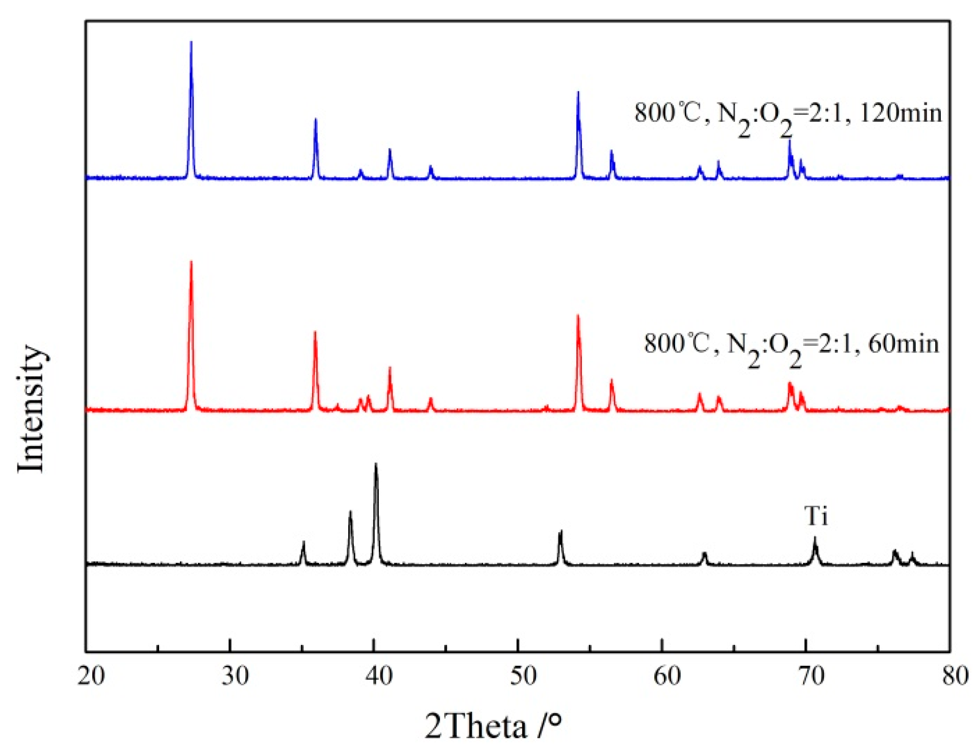
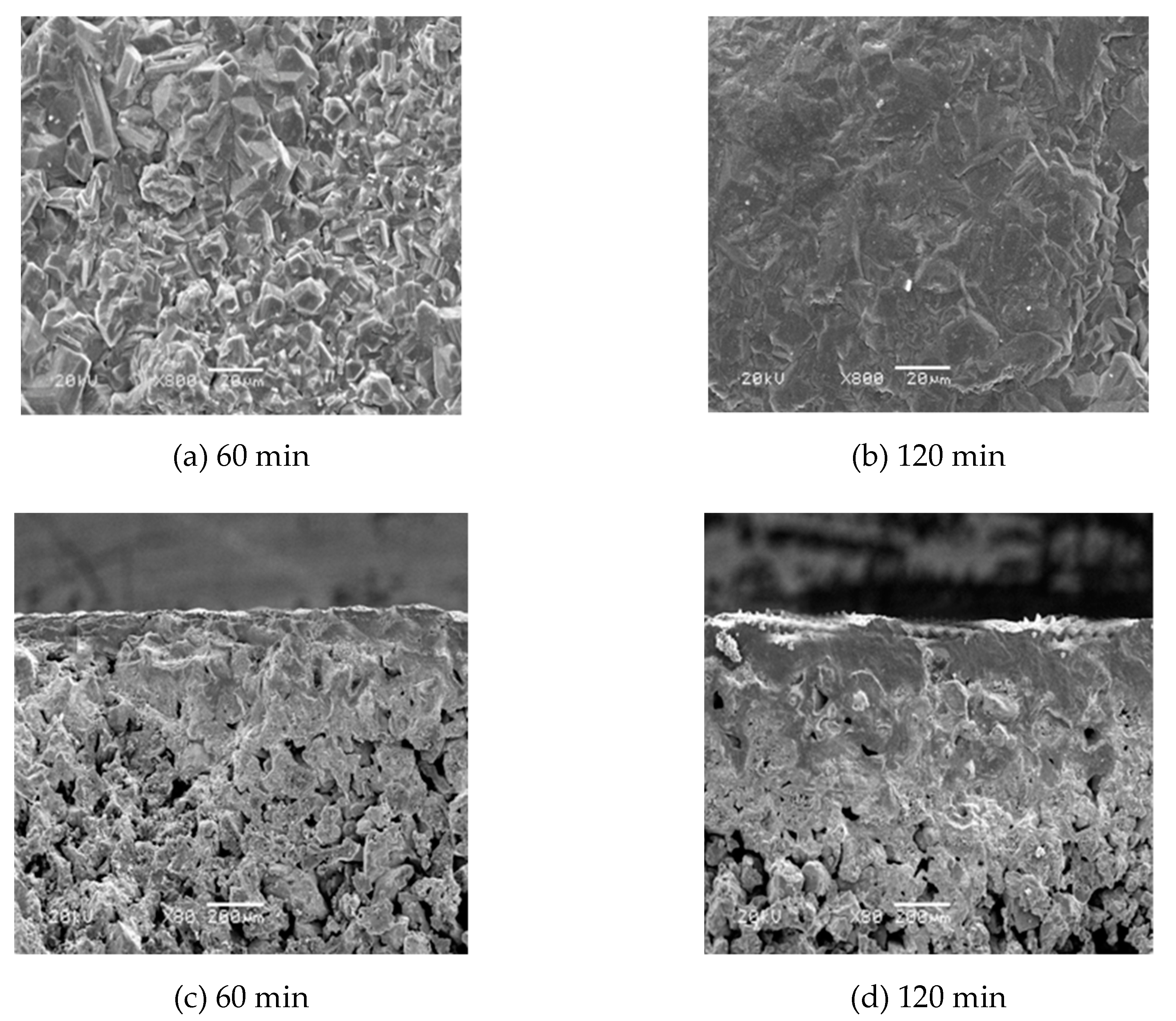
3.4. Effects of Oxidation Time on the Properties of TiO2/Ti Composite Membranes

The effects of different oxidation time on the properties of TiO2/Ti composite membranes were investigated under the condition of oxidation concentration N2:O2 = 2:1 and oxidation temperature of 800 °C.
The surface and cross-section morphology of the porous Ti support are shown in Figure 10 after oxidation at 800 °C and N2:O2 = 2:1 for different times. It can be seen from the surface SEM image that the surface of the Ti particles of the support changed significantly after 60 min of oxidation, when a continuous and flat oxide layer formed on the surface of the support. The surface morphology after oxidation for 120 min demonstrated that the oxide layer on the surface of the support was uniform and flat, but the surface portion was completely dense, resulting in a decrease or loss of the gas permeation rate of the support. From the cross-sectional SEM image, it can be observed that the thickness of the oxide layer gradually increased as the oxidation time increased. After 60 min of oxidation, a complete oxide film layer was formed on the surface, and oxidation was observed in the area near the surface of the support. The thickness of the formed oxide layer was thinner, and the internal pore structure of the support was less affected. The surface of the support oxidized for 120 min, formed a thick oxide film layer, and the inner pores of the support were also severely oxidized, which affected the gas flux and stability of the composite membrane.
The composite membranes prepared at different times were analyzed through the X-ray diffraction (XRD) method. As shown in Figure 11, compared to the results of the XRD diffraction analysis of Ti support, the characteristic peaks of titanium on the surface of the support could not be analyzed after in situ oxidation treatment of the support for different times, under this oxidation condition; only the characteristic peak of the rutile was observed.
A gas permeation device was used to test the gas flux of the Ti support after oxidation at 800 ℃, N2:O2 = 2:1 for different times. The change curve is shown in Figure 12. The gas permeability flux decreased with an increase in oxidation time. This was mainly due to the fact that the surface of the support was thinner and the gas permeation flux was larger when the oxidation time was 60 min. However, a thick ceramic film layer was formed on the surface of the support under the oxidation condition of 120 min, and a large amount of oxidation had occurred near the surface of the film, resulting in a decrease in gas permeation flux.
In summary, the gas permeability test results combined with SEM characterization and XRD analysis showed that the optimal oxidation time of the Ti/TiO2 composite membrane was 60 min, when the oxygen concentration was N2:O2 = 2:1 and the oxidation temperature was 800 °C.

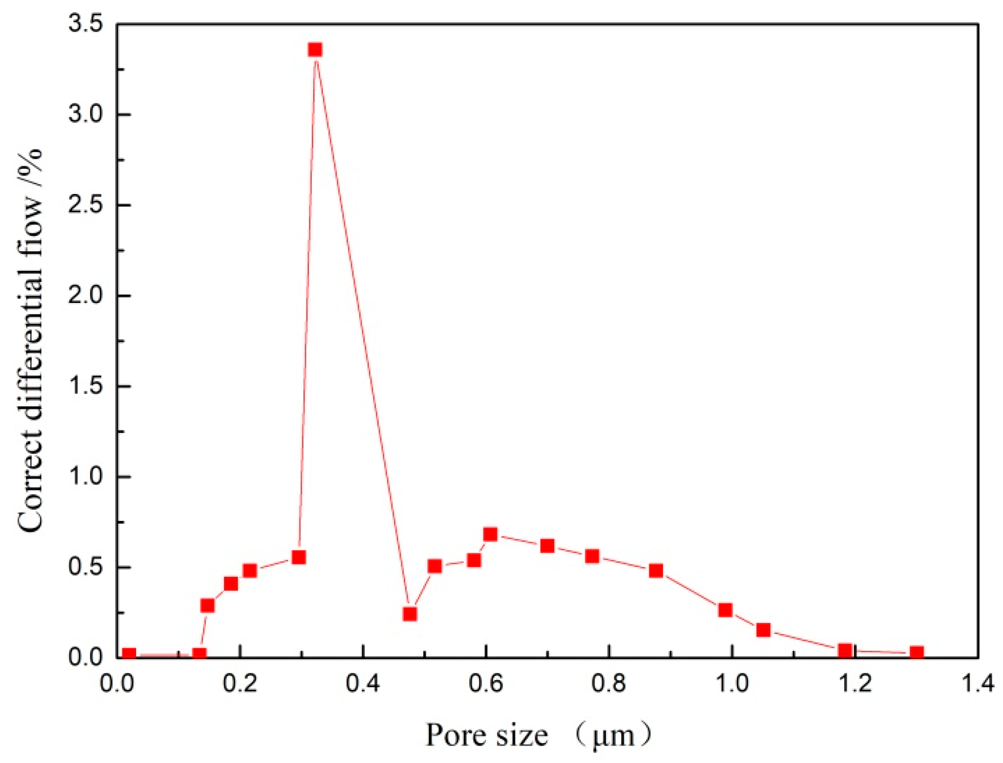
3.5. Pore Size Distribution Test of TiO2/Ti Composite Membrane

The TiO2/Ti composite membrane was prepared under the conditions of N2:O2 = 2:1, 800 °C for 60 min. The pore size distribution of the composite membrane was tested through the bubble pressure method. Figure 13 shows the pore size distribution of the TiO2/Ti composite membrane. As can be seen from the figure, the TiO2/Ti composite membrane had a narrow pore size distribution, and the mean pore-size was about 0.312 μm.

4. Conclusions

In this work, TiO2/Ti composite membranes were prepared through the in situ oxidation method, which effectively solved the binding force between the TiO2 ceramic layer and metal Ti support. Oxygen concentrations had a significant effect on the properties of TiO2/Ti composite membranes; with an increase in oxygen concentration, the surface TiO2 oxide layer gradually increased, partial oxidation also occurred inside the support near the membrane surface, which affected the performance of the composite membrane. The optimal oxygen concentration condition for preparing the TiO2/Ti composite membrane was N2:O2 = 2:1. Oxidation temperature and oxidation times also had a significant influence on the properties of the TiO2/Ti composite membranes. The optimum oxidation temperatures and oxidation times were 800 °C and 60 min, respectively. Under optimal conditions, the prepared TiO2/Ti composite membranes had a uniform thickness, a smooth surface, and only a rutile TiO2 characteristic peak. The TiO2/Ti composite membranes also had a good stability and a narrow pore diameter distribution, the mean pore diameter was about 0.312 μm.

Author Contributions

Conceptualization, D.Z.; Data curation, N.S.; Investigation, Y.M.; Methodology, P.Y. and H.L.; Writing—original draft, D.Z. All authors have read and agreed to the published version of the manuscript.

Funding

This work was supported by the National Nature Science Foundation of China (No. 212006065; No. 21666018).

Conflicts of Interest

The authors declare no conflict of interest.

References

  1. Ahmad, N.A.; Leo, C.P.; Ahmad, A.L. Synthesis of superhydrophobic aluminamembrane: Effects of sol-gel coating, steam impingement and water treatment. Appl. Surf. Sci. 2013, 284, 556–564. [Google Scholar] [CrossRef]
  2. Cai, Y.Y.; Chen, X.F.; Wang, Y.; Qiu, M.H.; Fan, Y.Q. Fabrication of palladium-titania nanofil-tration membranes via a colloidal sol-gel process. Micropor. Mesopor. Mater. 2015, 201, 202–209. [Google Scholar] [CrossRef]
  3. Xu, Z.; Michos, I.; Wang, X.R.; Yang, R.D.; Gu, X.H.; Dong, J.H. A zeolite ion exchange mem-brane for redox flow batteries. Chem. Commun. 2014, 50, 2416–2419. [Google Scholar] [CrossRef] [PubMed]
  4. Bowker, M.; James, D.; Stone, P.; Perkins, N.; Millard, L.; Greaves, J.; Dickinons, A. Catalysis at the metal-support interface: Exemplified by the photocatalytic reforming of methanol on Pd/TiO2. J. Catal. 2003, 217, 427–433. [Google Scholar] [CrossRef]
  5. Ma, Y.H.; Akis, B.C.; Aythurk, M.E.; Guazzone, F. Characterization of intermetallic diffusion barrier and alloy formation for Pd/Cu and Pd/Ag porous stainless steel composite membranes. Ind. Eng. Chem. Res. 2004, 43, 2936–2945. [Google Scholar] [CrossRef]
  6. Meulenberg, W.A.; Mertens, J.; Bram, M.; Buchkremer, H.P.; Stover, D. Graded porous titania membranes for microfiltration. J. Eur. Ceram. Soc. 2006, 26, 449–454. [Google Scholar] [CrossRef]
  7. Benfer, S.; Arki, P.; Tomandl, G. Ceramic membranes for filtration applications—Preparation and characterization. Adv. Eng. Mater. 2004, 6, 495–500. [Google Scholar] [CrossRef]
  8. Zhao, L.; Bram, M.; Buchkremer, H.P.; Stover, D.; Li, Z. Preparation of TiO2 composite microfiltration membranes by the wet powder spraying method. J. Membr. Sci. 2004, 244, 107–115. [Google Scholar] [CrossRef]
  9. Wu, L.Q.; Huang, P.; Xu, N.P.; Shi, J. Effects of sol properties and calcination on the performance of titania tubular membranes. J. Membr. Sci. 2000, 173, 263–273. [Google Scholar] [CrossRef]
  10. Ding, X.B.; Fan, Y.Q.; Xu, N.P. A new route for the fabrication of TiO2 ultrafiltration membranes with suspension derived from a wet chemical synthesis. J. Membr. Sci. 2006, 270, 179–186. [Google Scholar] [CrossRef]
  11. Adan, C.; Marugan, J.; Mesones, S.; Casado, C.; Grieken, R. Bacterial inactivation and degradation of organic molecules by titanium dioxide supported on porous stainless steel photocatalytic membranes. Chem. Eng. J. 2017, 31, 29–38. [Google Scholar] [CrossRef]
  12. Zhang, F.; Zheng, Y.H.; Hua, L.L.; Hu, N.; Zhu, M.H.; Zhou, R.F.; Chen, X.S.; Kita, H. Preparation of high-flux zeolite T membranes using reusable macroporous stainless steel supports in fluoride media. J. Membr. Sci. 2014, 456, 107–116. [Google Scholar] [CrossRef]
  13. He, Y.H.; Jiang, Y.; Xu, N.P.; Zou, J.; Huang, B.Y.; Liu, C.T.; Liaw, P.K. Fabrication of Ti-Al micro/nanometer-sized porous alloys through the kirkendall effect. Adv. Mater. 2007, 19, 2102–2106. [Google Scholar] [CrossRef]
  14. Zhan, M.J.; Li, G.; Wei, Q.; Cui, H.L.; Lin, L. Preparation of porous TiO2/Ti composite membrane for immunoisolation. Appl. Surf. Sci. 2008, 255, 2256–2258. [Google Scholar]
  15. Lin, Y.Q.; Cai, Y.Y.; Drioli, E.; Fan, Y.Q. Enhancing mechanical and photocatalytic performances on TiO2/Ti composite ultrafiltration membranes via Ag doping method. Separ. Purif. Technol. 2015, 145, 29–38. [Google Scholar] [CrossRef]
  16. Lin, Y.Q.; Cai, Y.Y.; Qiu, M.H.; Drioli, E.; Fan, Y.Q. Environment-benign preparation of Ag toughening TiO2/Ti tight ultrafiltration membrane via aqueous sol-gel route. J. Mater. Sci. 2015, 50, 5307–5317. [Google Scholar] [CrossRef]
  17. Lin, Y.Q.; Zou, D.; Chen, X.F.; Qiu, M.H.; Kameyama, H.; Fan, Y.Q. Low temperature sintering preparation of high-permeability TiO2/Ti composite membrane via facile coating method. Appl. Surf. Sci. 2015, 349, 8–16. [Google Scholar] [CrossRef]
  18. Mao, H.Y.; Bu, J.W.; Qiu, M.H.; Ding, D.; Chen, X.F.; Verweij, H.; Fan, Y.Q. PZT/Ti composite piezoceramic membranes for liquid filtration: Fabrication and self-cleaning properties. J. Membr. Sci. 2019, 581, 28–37. [Google Scholar] [CrossRef]
  19. Corni, I.; Ryan, M.P.; Boccaccini, A.R. Electrophoretic deposition: From traditional ceramics to nanotechnology. J. Eur. Ceram. Soc. 2008, 28, 1367–1383. [Google Scholar] [CrossRef]
  20. Chen, C.Y.; Chen, S.Y.; Liu, D.M. Electrophoretic deposition forming of porous alumina membranes. Acta Mater. 1999, 47, 2717–2726. [Google Scholar] [CrossRef]
  21. Zhang, D.Q.; Wu, J.Y.; Li, B.; Fan, Y.Q. Preparation of ceramic membranes on Ti-Al alloy supports by an in-situ oxidation method. J. Membr. Sci. 2015, 476, 554–560. [Google Scholar] [CrossRef]
  22. Zhou, S.Y.; Fan, Y.Q.; He, Y.H.; Xu, N.P. Preparation of titania microfiltration membranes supported on porous Ti–Al alloys. J. Membr. Sci. 2008, 325, 546–552. [Google Scholar] [CrossRef]
  23. Zhou, S.Y.; Zhong, Z.X.; Fan, Y.Q.; Xu, N.P.; He, Y.H. Effects of sintering atmosphere on the microstructure and surface properties of symmetric TiO2 membranes. Chinese. J. Chem. Eng. 2009, 17, 739–745. [Google Scholar]
Figure 1. SEM of porous Ti support.
Processes 08 00213 g001
Figure 2. TG curve of porous Ti support.
Processes 08 00213 g002
Figure 3. XRD of the porous Ti support.
Processes 08 00213 g003
Figure 4. Surface and cross-section morphology of Ti support after oxidation at 800 °C for 60 min, at different oxygen concentrations.
Processes 08 00213 g004aProcesses 08 00213 g004b
Figure 5. XRD pattern of Ti support after oxidation at 800 °C for 60 min, at different oxygen concentrations.
Processes 08 00213 g005
Figure 6. Gas flux of Ti support after oxidation at 800 °C for 60 min, at different oxygen concentrations.
Processes 08 00213 g006
Figure 7. The surface and cross-section of Ti support after oxidation under N2:O2 = 2:1, for 60 min at different temperatures.
Processes 08 00213 g007
Figure 8. XRD pattern of the Ti support after oxidation under N2:O2 = 2:1, for 60 min at different temperatures.
Processes 08 00213 g008
Figure 9. Gas flux curve of the Ti support after 60 min of oxidation at different temperatures.
Processes 08 00213 g009
Figure 10. The surface and cross-section of Ti support after oxidation at different times (800 °C, N2: O2 = 2:1).
Processes 08 00213 g010
Figure 11. XRD pattern of Ti support after oxidation at different temperatures (800 °C, N2:O2 = 2:1).
Processes 08 00213 g011
Figure 12. The gas flux curve of Ti support after oxidation at different times (800 °C, N2:O2 = 2:1).
Processes 08 00213 g012
Figure 13. The pore size distribution of the TiO2/Ti composite membrane after oxidation under N2:O2 = 2:1 at 800 °C for 60 min.
Processes 08 00213 g013
Table 1. Quality change of the TiO2/Ti composite membrane before and after ultrasonic cleaning.
SampleMbefore/gOxidizing Condition N2:O2Mafter/gΔMm1m2m3
1#6.02800 °C/60 min2:17.681.627.667.637.62
2#6.18800 °C/60 min1:17.961.827.957.957.92
3#6.17800 °C/60 min1:28.182.018.188.168.13

