Article

Novel Concept of Cogeneration-Integrated Heat Pump-Assisted Fractionation of Alkylation Reactor Effluent for Increased Power Production and Overall CO2 Emissions Decrease

1
Department of Chemical and Biochemical Engineering, Faculty of Chemical and Food Technology, Slovak University of Technology, Radlinského 9, 812 37 Bratislava, Slovakia
2
Department of Process Engineering, Faculty of Manufacturing Technologies of the TU of Kosice with a seat in Prešov, Technical University of Košice, Štúrova 31, 080 01 Prešov, Slovakia
3
SLOVNAFT, a.s., Vlčie hrdlo 1, 824 12 Bratislava, Slovakia
*
Author to whom correspondence should be addressed.
Processes 2020, 8(2), 183; https://doi.org/10.3390/pr8020183
Submission received: 31 October 2019 / Revised: 16 January 2020 / Accepted: 29 January 2020 / Published: 5 February 2020
(This article belongs to the Special Issue Energy, Economic and Environment for Industrial Production Processes)

Abstract

:
Alkylate produced by catalyzed reaction of isobutane and olefin-rich streams is a desired component for gasoline blending. Fractionation of the alkylation reactor effluent is energy demanding due to the presence of close boiling point components and solutions cutting its energy intensity; expenses associated with this process are investigated intensely nowadays. This paper presents a novel conceptual design and techno-economic analysis of alkylation reaction effluent fractionation revamp to reach a cut in energy costs of the fractionation process without the need to revamp the rectification columns themselves, providing thus an alternative approach to a more sustainable alkylation process. Two cases are considered—A. additional steam turbine installation or B. combustion engine-driven heat pump-assisted rectification. Mathematical modeling of the considered system and its revamp is applied using the “frozen technology” approach. Real system operation features and seasonal variations are included considering the refinery’s combined heat and power (CHP) unit operation and CO2 emissions balance both internal and external to the refinery. Case A yields an expectable yearly benefit (saved energy minus additionally consumed energy minus CO2 emissions increase; expressed in financial terms) of €110–140 thousand, net present value (NPV) of −€18 to €272 thousand and produces 3.3 GWh/year of electric energy. Case B delivers a benefit of €900–1200 thousand, NPV of −€293 to €2823 thousand while producing 33 GWh/year of electricity. Both cases exhibit analogous simple payback periods (8–10 years). Marginal electric efficiency of Case B (78.3%) documents the energy integration level in this case, exploiting the system and CHP unit operation synergies. CHP unit summer operation mode and steam network restrictions significantly affect the seasonal benefit of Case B. CO2 emissions increase in both cases, Case A and Case B, considering the refinery level. However, including external CO2 emissions leads to emissions decrease in both cases of up to 26 kton/year (Case B.) The presented results document the viability of the proposed concepts comparable to the traditional (reference) solution of a high performance (COP = 8) heat pump while their performance sensitivity stresses the need for complex techno-economic assessment.

1. Introduction

Oil and Gas industry is an important contributor to total worldwide industrial energy consumption and emissions production [1]. Due to the complex nature of the applied processes and unit operations, performing in a wide range of temperatures and pressures shows a significant possibility for energy intensity improvement in this industry sector [2]. Product separation and fractionation account for the majority of energy costs in refining [3] and much effort has been invested in the last decades to both optimize existing processes and to develop novel ones [4].
The alkylate production process underwent significant changes in the last few decades [5]. Traditionally used homogeneous catalysis is gradually being replaced by solid catalysts (acidic resins) [6] or ionic liquids [7]. Hydrofluoric acid, used in older plants [8], is ruled out as the catalyst due to safety and environmental issues. Improved mixing of reactants and catalysts continues to be of importance in the existing plants’ revamps [9] while innovative reactor designs utilizing the micromixing concept [10] are developed. Deeper investigation of the accompanying effects by the combined experimental–numerical approach was employed by Tsadkin et al. [11], followed by the pilot plant test of a novel reactor type [12]. The separation part of this technology has received much attention as well. An optimization study by García [5] assessed the economic and environmental impacts of various reactor refrigeration alternatives and product fractionation layouts. The complex plant modeling approach was presented by Li [13], introducing design solutions leading either to the lowest global warming potential or to the highest economic potential. Yet another research group has dealt with the alkylate production process modeling within a wider scope of the gasoline blending optimization [14,15].
Alkylation reactor effluent is a mixture of hydrocarbons, predominantly of unreacted isobutane, n-butane, and alkylate, accompanied by impurities such as propane. Energy costs of this mixture splitting usually represent a major part of the total energy costs of the alkylation process. Traditional separation layout includes i-butane separation in the first column, followed by splitting of n-butane and alkylate in the second one [13]. Advanced distillation techniques can be applied to lower the energy consumption, e.g., thermal coupling [16], heat pump incorporation [16], or divided wall column [5]. Thermal coupling of distillation columns is traditionally proposed as an energy efficient system used in combination with pressure change [17]. Heat pump application is mostly limited to close boiling point mixtures fractionation [18], such as alkanes [19] or other mixtures of hydrocarbon gases [20]. Application in different systems, such as benzene-toluene mixtures, has been studied recently [21]. Heat pump driver is in most cases an electromotor [16] or a steam turbine [22]. Divided wall column design can be applied in similar situations as the abovementioned advanced distillation techniques [23]. Combination of several techniques in one application results in further reduction of energy consumption while increasing the system complexity [24,25]. Designs that do not lead to heat consumption reduction but enable using a lower potential heat include side reboilers [26,27] or additional power production through enhanced cogeneration [26].
Deeper study of the compression heat pump technology and its application showed multiple examples of its application in the available literature, even in industrial sphere [28]. Several heat pump designs were studied from the techno-economic point of view in [28], which are able to deliver useful heat at temperatures over 100 °C. Compression heat pump applications in various industry branches, including sugar production and paper drying have been presented in a best practice brochure by the U.S. Department of Energy [29], while other ones in refining, petrochemistry, and gases fractionation were reported in [19,22,24]. Significant energy intensity decrease in the aromatics fractionation process can be achieved by optimized compression heat pump design in [21] with similar findings presented in [24] for acetone-methanol mixture splitting. Ethane-ethylene and propane-propylene splitting is a typical large-scale industrial process where a compression heat pump is used as a well-proven technology [16,22]. Application of a condensing steam turbine-driven compression heat pump for C3 fraction splitting is described in [22] in more detail. A typical simple payback period of 2 to 5 years can be expected in industrial compression heat pump applications [29] where the fuel saving objective is pursued and heat is produced by fuel combustion without electric energy cogeneration.
Retrofitting an existing production process with the mentioned techniques yields problems with equipment capacity. To prevent technical feasibility problems, space constrictions have to be considered as well [30]. It is also crucial to assess seasonal system operation variations, both from a process as well as from an energy supply point of view. Cogeneration units, serving as energy suppliers for production processes, are operated in different regimes throughout the year [31], which results in a whole range of possible impacts of a process retrofit on the resulting energy and economic balance. Saving of low or middle pressure steam targeted by such measures is accompanied by cogenerated electric energy production decrease in the combined heat and power (CHP) unit [32]; thus, a “better” retrofit is to be compared with an already existing “efficient” energy production and consumption scheme. Available papers on the alkylation process optimization usually take into account fixed utilities’ prices, which may not fully represent the real impact of the optimization process on the energy and cost balance of the whole plant. Incorporating the abovementioned effects is vital for the economic assessment of any retrofit proposal.
The goals of the presented study include introducing a novel concept of the products fractionation retrofit in the alkylation process, that, on the contrary to other retrofit options, does not require resizing or rebuilding of fractionation columns and formulating and testing a general framework for the refinery-wide economic assessment of the fractionation retrofit proposals, proving that the novel retrofit concept is economically competitive with the reference retrofit solutions. Thereby, a knowledge gap in the literature is filled and a contribution towards an energy efficient and more sustainable production process is achieved. Moreover, energy managers are provided with a general retrofit assessment method which facilitates better investment planning.
The general problem formulation comprises (I) a comparison of the traditionally applied fractionation process retrofit in terms of capital expenses needed and impact on site-wide energy balance; (II) a description of the novel retrofit concept; (III) a definition of the marginal water steam and electricity sources for the process, including the combined heat and power unit (CHP) assessment. The method applied in the techno-economic assessment of the formulated problem uses (I) a mathematical model assessing the fractionation process, combined heat and power unit (CHP) operation, and steam and electricity balances; (II) total equipment costs calculation; (III) yearly benefit and simple payback period calculation. The paper organization follows the concept described above. Problem formulation and method description are followed by the results and discussion part and the concluding remarks.

2. Materials and Methods

2.1. General Problem Superstructure and Assessment

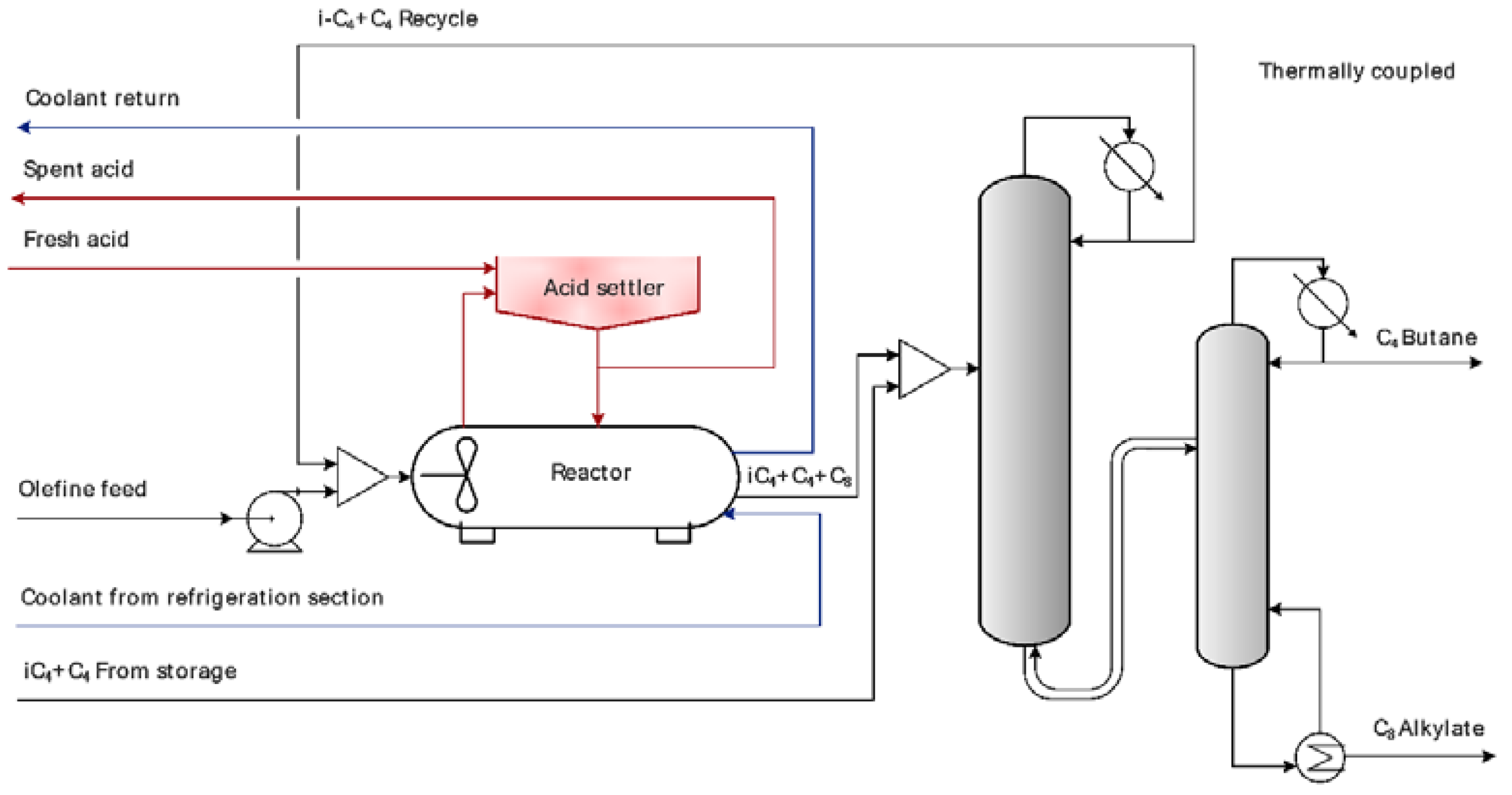
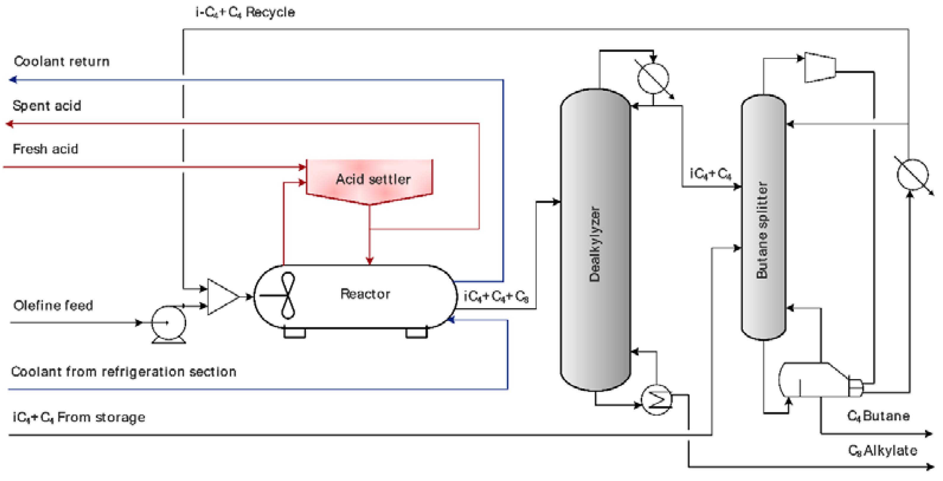
Figure 1 provides a typical Alkylation plant layout. Alkylate, a high octane number gasoline component, is produced by catalyzed reaction of isobutane-rich and butane-rich hydrocarbon streams in a continuously stirred tank reactor. The alkylation reactor is refrigerated to reach the desired reaction temperature whereby side reactions are suppressed and high quality alkylate is produced. Reactor effluent is fractionated into i-butane recycle stream, n-butane stream, and alkylate stream. C3 stream can be drawn off from the refrigeration unit or from the first column condenser as uncondensed gas. Fractionation of butanes by conventional rectification is energy-intensive due to their close boiling points and the presence of alkylate increases the boiling point of the mixture, preventing direct use of waste heat plentifully available in the refineries at temperatures typically below 80 °C to be supplied to the reboiler. Solutions possibly improving the plant energy efficiency are depicted in Figure 2, Figure 3 and Figure 4. All of them require different rectification columns’ sizes than conventional splitting depicted in Figure 1; thus, their application ex-post as a part of unit revamp is quite costly, including at least one new rectification column.
A part of an alkylation unit operated in SLOVNAFT refinery is briefly presented in Figure 5. Reactor effluent is led to a deisobutanizer followed by a debutanizer, whereby the recycle stream, n-butane stream, and alkylate product are obtained. Heating steam for rectification columns is provided by the CHP unit. Heat content of steam condensates is partly used to preheat demineralized water for an adjacent production unit and the rest is directly utilized as washing water.
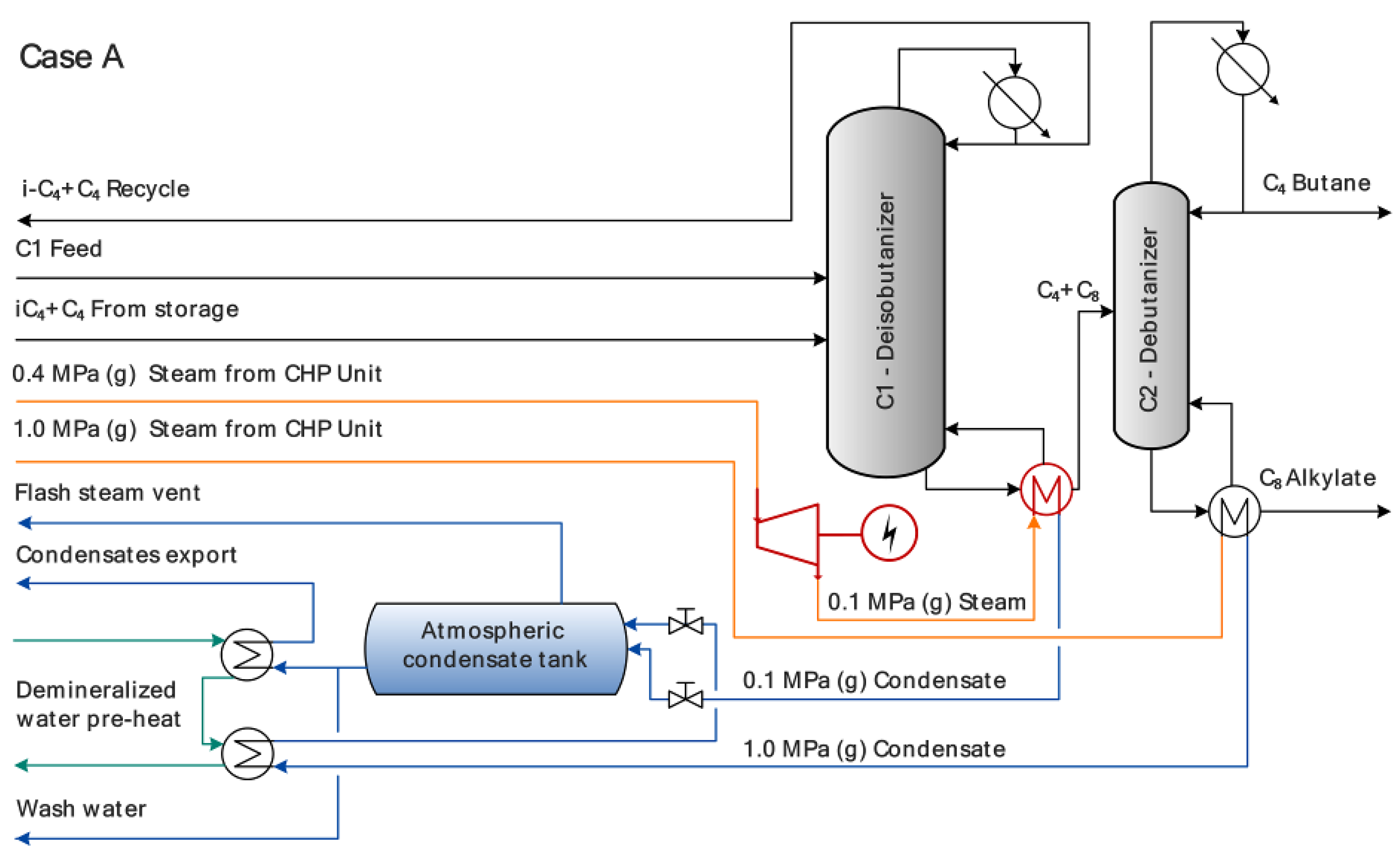
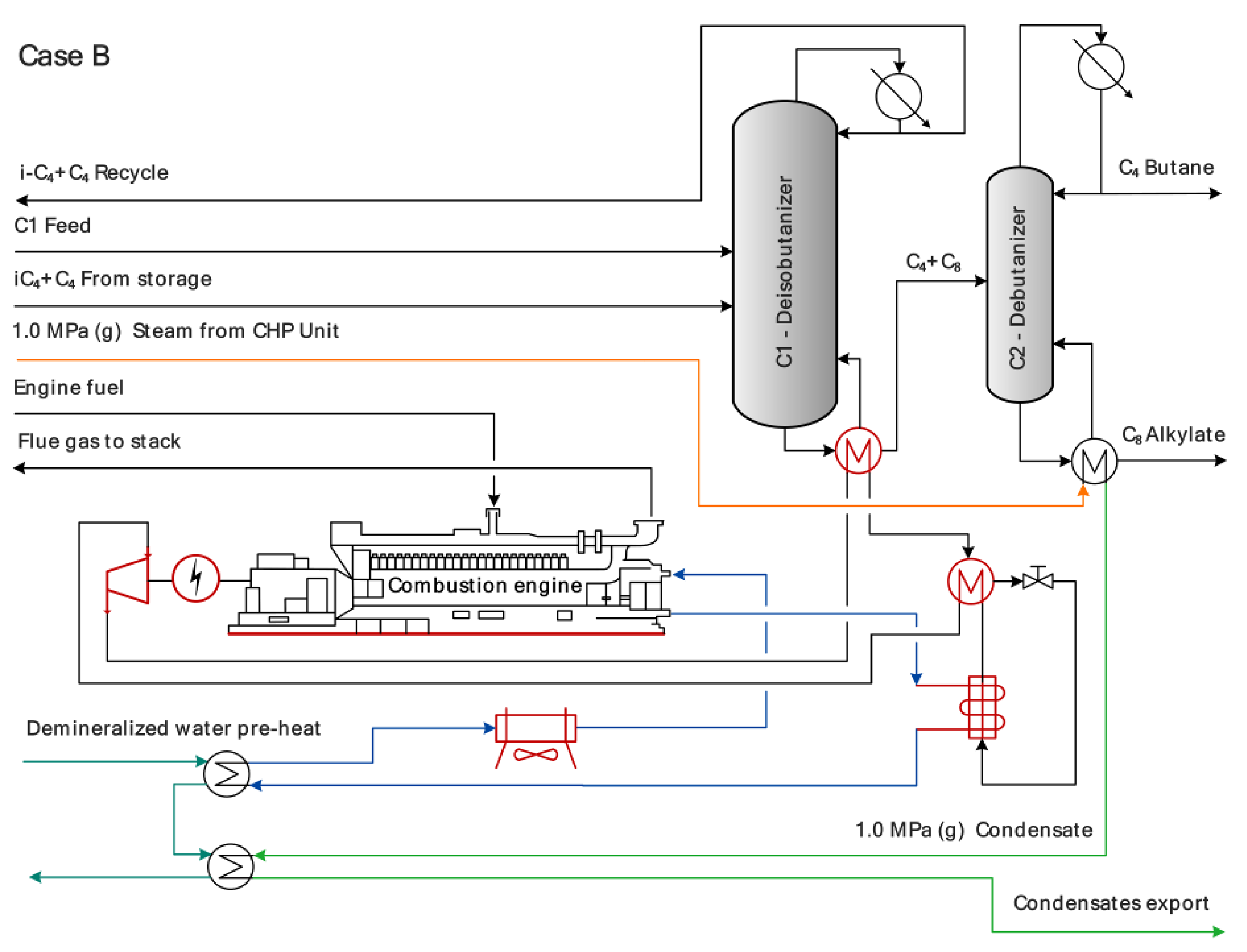
Alternative reactor effluent splitting revamp options can be applied to avoid rectification columns revamp. Figure 6 depicts the option of an additional steam turbine installation exploiting the available cogeneration potential and will be further referred to as “Case A”. Figure 7 represents a heat pump-assisted debutanizer with a combustion engine serving as both a heat pump driver and a heat source, further referred to as “Case B”. Such solution is unique and, to our knowledge, novel. It combines the advantage of highly efficient cogeneration using a combustion engine with heat pump-assisted rectification.

2.1.1. General Process Model

The process model encompasses material and heat balances of the deisobutanizer rectification column as it results from Figure 5, taking into account the following assumptions:
  • Feedstock quality and temperature remain constant throughout the evaluated time interval.
  • Ideal gas and ideal liquid behavior is assumed.
  • Pressure drop on each tray is equal, thus resulting in a linear pressure profile.
  • There is no radial temperature or pressure gradient.
  • The column reboiler operates at thermodynamic equilibrium.
  • Column bottoms leave the reboiler at boiling point.
  • Murphree tray efficiency is the same for each component.
  • Stage efficiencies along the column remain unchanged.
  • The column condenser operates as a total condenser; column distillate leaves the column at boiling point.
  • Vapor and liquid phases leaving each stage have the same temperature.
  • Pressure and heat losses in the system are negligible.
  • Column bottoms leave the reboiler at boiling point.
System calculations solve a square system of strongly nonlinear algebraic equations, the MESH equations. The acronym stands for Mass balances, phase Equilibrium relations, Summation equations, and Heat balances. Given the formulated model assumptions, Equations (1)–(5) for the i-th component at the j-th column stage are as follows:
  • material balance, Equation (1):
    M j , i 0 = L j 1 x j 1 , i L + V j + 1 y j + 1 , i V + F j x j , i F L j x j , i L V j y j , i V ,
  • phase equilibrium, Equation (2):
    E j , i 0 = y j , i V E j , i M V K j , i x j , i L ( 1 E j M V ) y j + 1 , i V ,
  • summation, Equations (3) and (4):
    S j V 0 = 1 i = 1 N y j , i V ,
    S j L 0 = 1 i = 1 N x j , i L ,
  • heat balance, Equation (5):
    H j , i 0 = L j 1 h j 1 L + V j + 1 h j + 1 V + F j h j F L j h j L V j h j V + Q ˙ .
Murphree stage efficiency, E j , i M V , used in Equation (2) is defined via Equation (6):
E j , i M V = y j , i V y j + 1 , i V K j , i x j , i L y j + 1 , i V ,
with vapor-liquid equilibrium constant, K j , i , defined in Equation (7) and saturated vapor pressure, P j , i ° , whose dependence on temperature was applied in the form of Equation (8):
K j , i = p j , i ° p j ,
p j , i ° = e ( A 1 i + A 2 i A 3 i + T j + A 4 i ln T j + A 5 i T j A 6 i ) .
Molar enthalpies of individual liquid streams, h j L , and feed stream, h j F , are based on their composition and molar heat capacities, c p j , i L , as it results from Equations (9) and (10). Molar heat capacities in the liquid phase for individual components were obtained from Equation (11):
h j L = i = 1 N I ( c p j , i L x j , i L ) ( T j T r ) ,
h j F = i = 1 N I ( c p j , i x j , i F ) ( T F T r ) ,
c p j , i L = B 1 i + B 2 i T j + B 3 i T j 2 + B 4 i T j 3 + B 5 i T j 4 .
Molar heat of vaporization, Δ v h j , i , is calculated via Equation (12) and contributes to molar enthalpies of vapor streams, h j V , obtained by Equation (13):
Δ v h j , i = C 1 i ( 1 T R j , i ) ( C 2 i + C 3 i T R j , i + C 4 i T R j , i 2 ) ,
h j V = i = 1 N I ( c p j , i L y j , i V ) ( T j T r ) + i = 1 N I y j , i V Δ v h j , i .
All column heat balances share the same reference state: T r = 273.15   K , liquidus.

2.1.2. Steam Consumption and Condensates Management

Heat consumption in the column reboiler, calculated in Equation (5), is converted to low pressure steam consumption, m ˙ L P S , by Equation (14), where the ( h L P S h L P S , c o n d ) term represents the enthalpy difference between inlet steam and leaving boiling steam condensate:
m ˙ L P S = Q ˙ r e b ( h L P S h L P S , c o n d ) .
According to Figure 5, steam condensates, after flashed to atmospheric pressure, are further utilized as washing water and a heating medium for demineralized water preheat for an adjacent production unit. A decrease in low pressure steam consumption leads to heat recuperation decrease and the missing preheated water heat content has to be replenished by additional low pressure steam consumption. Recuperated heat flux, Q ˙ r e c , in the water preheater is defined by Equation (15) and the additional low pressure steam consumption, m ˙ L P S , a d d , is obtained from Equation (16):
Q ˙ r e c = m ˙ d e m i c p H 2 O L ( t d e m i o u t t d e m i i n ) ,
m ˙ L P S , a d d = Q ˙ r e c ( h L P S h L P S , c o n d ) .

2.1.3. Heating Steam Pressure Reduction by Steam Turbine

Steam pressure reduction by a steam turbine can be applied to enhance electric energy production. Power production of the steam turbine, P s t , results from Equation (17) where m ˙ L P S represents the mass flow of the entering low pressure steam,   h L P S i n its specific enthalpy, and h d i s c h the specific enthalpy of discharge steam. Mechanical efficiency of the steam turbine, η m e c h , is also considered in this Equation:
P s t = m ˙ L P S ( h L P S i n h d i s c h ) η m e c h .
Discharge steam enthalpy is estimated as a function of inlet steam conditions, discharge pressure, and isoentropic efficiency, η I S , of the steam turbine in Equation (18). Here, symbol h L P S I S represents discharge steam enthalpy after isoentropic (ideal) expansion:
h d i s c h = h L P S i n ( h L P S i n h L P S I S ) η I S .
Discharge steam is used in a new column reboiler and its discharge pressure depends on the allowable steam condensing temperature. Its lower limit of 107 °C can be considered (=steam pressure of 130 kPa) to ensure steam condensate leaving the new column reboiler at sufficiently high pressure to come to the atmospheric flash tank without the need of an additional condensate pump [33].

2.1.4. Combustion Engine-Driven Heat Pump

A combustion engine can be used as heat pump driver utilizing the heat released by the engine as a cheap heat source for the heat pump. Heat production oriented engine operation is the most efficient one as the heat pump utilizes all produced heat and the net power surplus reduces power purchase from the external grid. Large combustion engines using natural gas as fuel, producing several MWs of electric energy, can benefit from very high electric and heat efficiencies. Electric efficiency can exceed 40% or even 45% and the total efficiency of over 90% can be reached [34,35]. Heat is usually available in hot water, with fresh hot water having a temperature of 90 °C while the return water temperature is 70 °C. With a certain loss in engine heat efficiency, water temperatures can be increased by up to 10 °C. Such hot water is an excellent source of heat for the heat pump. Engine placement should, however, be considered carefully, including space constrictions, explosion hazard, and noise level [36].
Column reboiler heat duty is obtained as a sum of heat utilized by the compression heat pump, Q ˙ h p , and the mechanical energy used to drive this heat pump, E ˙ h p (see Equation (19)):
Q ˙ r e b = Q ˙ h p + E ˙ h p .
Fuel consumption in the engine, Q ˙ e n g f u e l , and its net electric output, P e n g n e t , are readily obtained by Equations (20) and (21) with η t h representing the engine’s thermal efficiency and η e l the engine’s electric efficiency, respectively:
Q ˙ e n g f u e l = Q ˙ h p η t h ,
P e n g n e t = Q ˙ e n g f u e l η e l E ˙ h p .
Heat pump compressor mechanical energy demand, E ˙ h p , is estimated by Equations (22)–(24) based on the approach by Bejan [37]. It is strongly dependent on the pressure ratio the compressor has to deliver; i.e., the lower the reboiling temperature, the more energy efficient heat pump operation is achieved. Mass flow rate of working fluid in the closed heat pump cycle, m ˙ h p f l u i d , is calculated by Equation (24); η I S , h p represents the heat pump’s isoentropic efficiency and η m e c h , h p stands for the heat pump mechanical efficiency. The specific isoentropic (ideal) work of the heat pump, ( h h p o u t , I S h h p i n ) , results from Equation (23), where the used symbols have the following meaning: z ¯ is the mean compressibility factor value of the working fluid during its compression,   R is the universal gas constant,   T h p i n , f l u i d is the heat pump suction temperature, M f l u i d is the molar mass of the working fluid,   p h p o u t p h p i n is the ratio of discharge and suction pressure of the heat pump and κ ¯ is the mean Poisson’s coefficient value during compression:
E ˙ h p = m ˙ h p f l u i d ( h h p o u t , I S h h p i n ) η h p , I S η h p , m e c h ,
( h h p o u t , I S h h p i n ) = z ¯ R T h p i n , f l u i d ( ( p h p o u t p h p i n ) κ ¯ 1 κ ¯ 1 ) M f l u i d ,
m ˙ h p f l u i d = Q ˙ r e b ( h h p o u t , I S h h p i n ) .
Mean values of z and κ are obtained for the given working fluid from available literature [38]. Minimum required heat transfer driving force for heat pump evaporator, Δ t e v a p m i n , and for column reboiler, Δ t r e b m i n , can be defined by Equations (25) and (26). t h e a t m i n represents the minimum temperature of the heat available for the heat pump, t e v a p f l u i d stands for the evaporation temperature of the working fluid in the heat pump evaporator, t r e b , c o n d f l u i d represents the condensing temperature of the working fluid in the heat pump condenser (=column reboiler), and t r e b is the process side temperature in the column reboiler.
Δ t e v a p m i n = t h e a t m i n t e v a p f l u i d
Δ t r e b m i n = t r e b , c o n d f l u i d t r e b
Heat pump compressor suction pressure, p h p i n , is set as identical to the working fluid pressure in the evaporator, p e v a p ° , and the heat pump discharge pressure, p h p o u t , is set as identical to the working fluid pressure in the condenser, p h p ° . Equation (8) defines the relation between the values of pressure in the heat pump evaporator and condenser and the related fluid temperatures t e v a p f l u i d and t r e b , c o n d f l u i d .
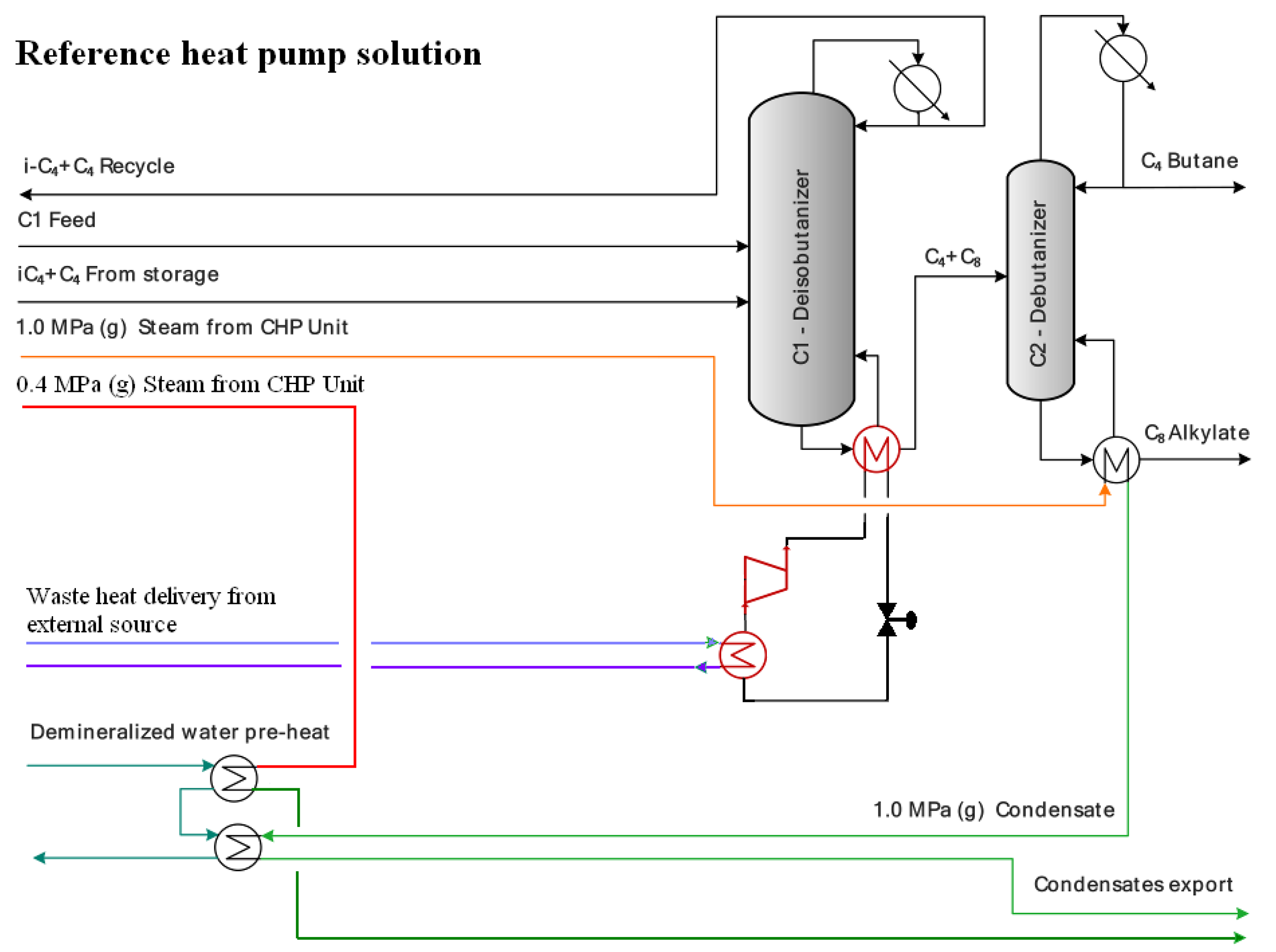
A traditional compression heat pump driven by an electromotor is introduced as a reference solution to compare its economic feasibility with the engine-driven one. The corresponding process diagram is provided in Figure 8. It is assumed that sufficient heat is available for free at sufficiently high temperature to be utilized by such a heat pump. Its power consumption can be estimated for a range of coefficients of performance, COP, as it results from Equation (27).
C O P = Q ˙ r e b E ˙ h p

2.1.5. Combined Heat and Power Unit (CHP) and Refinery’s Electric Energy Balance

Detailed description of a standard CHP unit found in a refinery is provided in [39]. It usually consists of steam boilers producing very high pressure steam and a set of both backpressure and extraction-condensing steam turbines. Heavy fuel oil is the usual fuel combusted in steam boilers. Steam is expanded to several pressure levels and exported to the refinery. Usually, high pressure (2–4 MPa), middle pressure (around 1 MPa), and low pressure (around 0.5 MPa) steam meet the refinery’s requirements. Steam condensates from the refinery can be returned to the CHP unit, reducing fuel consumption in the boilers.
Marginal thermal efficiency of the CHP unit, η e l , m a r g , C H P , and marginal backpressure electric energy production rates, e b p , m a r g , C H P . s , obtained by expanding steam in steam turbines to individual discharge pressure levels, s , can be used to assess the impact of steam balance change on the CHP unit operation [39].
Change in the CHP unit backpressure power production, Δ P b p , C H P , results from Equation (28), taking into account steam export change at individual steam pressure levels, Δ m ˙ C H P , s and the corresponding marginal backpressure electric energy production:
Δ P b p , C H P = s Δ m ˙ C H P , s e b p , m a r g , C H P , s .
Overall power import change of the refinery, Δ P i m p , is obtained by Equation (29) as a sum of the CHP unit’s power production change and the refinery’s power consumption change, Δ P r e f . :
Δ P i m p = Δ P b p , C H P + Δ P r e f .
Energy efficiency of a combustion engine-driven heat pump installation can be assessed via its marginal electric efficiency calculation, η e l , m a r g , e v a l , Equation (30), where L H V f u e l , f stands for the f-th fuel lower heating value and the change in each f-th fuel consumption is represented by Δ m ˙ f u e l , f :
η e l , m a r g , e v a l = Δ P i m p f Δ m ˙ f u e l , f L H V f u e l , f .

2.1.6. CO2 Emissions from Combustion Processes and External Power Production

Complete combustion of fuels can be assumed for both steam boilers and the combustion engine. Thus, CO2 production rate change, Δ m ˙ C O 2 , f , on the refinery level, can be generally estimated from Equation (31), taking into account the mass fraction of carbon in each f-th fuel consumption in the refinery and in the CHP unit, w C , f f u e l , the change in each f-th fuel consumption, Δ m ˙ f u e l , f , and the molar mass of carbon (12.01 g/mol) and that of CO2 (44.01 g/mol):
Δ m ˙ C O 2 , f = f Δ m ˙ f u e l , f w C , f f u e l 44.01   g . m o l 1 12.01   g . m o l 1 .
A change in electric energy production or consumption within a refinery causes an adequate power production change in external units. CO2 emissions that accompany this change can be estimated either using average emission factor resulting from a national energy mix or marginal emission factor [40] (Equation (32)). In this equation, Δ m ˙ C O 2 , e x t represents the external CO2 emissions change, Δ P i m p is the power import change of the refinery, and f C O 2 , e x t is the suitable CO2 emission factor from power production:
Δ m ˙ C O 2 , e x t = Δ P i m p f C O 2 , e x t .
Including the external change of CO2 emissions in the overall CO2 emissions change, Δ m ˙ C O 2 , o v e r a l l , Equation (33), provides a more representative assessment of the environmental impact of the considered process changes in the refinery:
Δ m ˙ C O 2 , o v e r a l l = Δ m ˙ C O 2 , r e f + Δ m ˙ C O 2 , e x t .

2.1.7. Economic Assessment

Economic assessment of the proposed project comprises estimation of the total investment costs and the benefit resulting from the project. Total investment cost, TIC, can be obtained considering the key equipment cost and indexing it by suitable cost factors [41] and from incorporating information from local staff about total investment costs of past actions. Cost indices should be used to transform the past cost data to the future project realization time [41,42]. Hourly benefit, B ˙ h , is calculated from Equation (34) and includes the hourly change in fuel costs, Δ C ˙ f u e l (Equation (35)) with f = 1 and 2 denoting the heavy fuel oil and natural gas, the hourly change in electric energy costs, Δ C ˙ e l (Equation (36)), and the hourly change in costs associated with CO2 emissions, Δ C ˙ C O 2 (Equation (37)). Finally, the simple payback period, PBP, is defined by Equation (38) that, along with the yearly benefit, h = 1 6168 B ˙ h , and the CO2 balance, is a basic measure of the project economic feasibility. The summation of over 6168 h represents the cumulative duration of stable alkylation unit operation in the one year lasting evaluation period.
B ˙ h [ e u r o . h 1 ] = Δ C ˙ f u e l + Δ C ˙ e l + Δ C ˙ C O 2 ,
Δ C ˙ f u e l = f = 1 2 Δ m ˙ f u e l , f L H V f u e l , f c f u e l , f ,
Δ C ˙ e l = ( Δ P b p , C H P + P e n g n e t ) c e l , g e n + Δ P r e f c e l , r e f ,
Δ C ˙ C O 2 = Δ m ˙ C O 2 , r e f c C O 2 ,
P B P = T I C h = 1 6168 B ˙ h .
Symbol c f u e l , f in Equation (35) represents the cost of f-th fuel per GJ fuel energy and L H V f u e l , f stands for its lower heating value. Different electric energy prices for generated electric energy, c e l , g e n , and electric energy consumed in the refinery, c e l , r e f , can be used in Equation (36), if the legislation imposes certain fees on in-house electricity production, as discussed in [43]. CO2 emissions cost, c C O 2 , is used in Equation (37). Application of this approach to simple payback period estimation includes the “frozen technology” assumption [44], meaning that the technology is operated with the same feed rates and produces products of the same quality as in the evaluation period. Net present value (NPV) is calculated using Equation (39) based on model discount rate of d = 10% for refining and petrochemistry [45], on the average EU 28 2007–2018 inflation rate of n = 1.74% [46], on the expected plant service life of 20 years, with revamp being performed in the 0-th year and with a ranging from 1 to 20.
N P V = T I C + a = 1 20 h = 1 6168 B ˙ h . ( 1 + n 100 ) a ( 1 + d 100 ) a

2.2. Calculations and Methods

2.2.1. Process Model

In general, to fully characterize a rectification column, all degrees of freedom have to be fully defined. The number of degrees of freedom,   N D F , is defined by Equation (40):
N D F = N I + 6 .
where N I stands for the number of components [47]. As the proposed model assumes five components, the overall number of degrees of freedom that have to be defined is 11. The basic set-up consists of a known flow rate, temperature, pressure/vapor fraction, and composition of the feedstock (1 + 1 + 1 + 4, as only four out of five components can be defined) and conditions in the column condenser (temperature, pressure; 1 + 1). Thus, still two degrees of freedom remain to be defined which include the composition of one of the components in the column bottoms and the reflux ratio. While the reflux ratio was calculated for each evaluated day separately based on the actual measured column performance, the bottoms’ quality requirement was fixed to be a constant number according to technological requirements. Table 1 sums up the fixed values of model inputs with the degrees of freedom marked “*”.
This system was solved using the simultaneous correction (SC) method in MATLABTM environment. While this method requires significantly higher computational capacity in comparison to other conventionally used methods (e.g., Inside-Out method), it is capable of converging even with incorrect initial estimate of temperature and concentration profiles in a couple of iterations [48].
Constants used in Equation (8) for saturated vapor pressure are provided in Table 2 and those used in Equation (11) for the estimation of molar heat capacities in liquid phase are listed in Table 3. Table 4 contains constants used to estimate molar heat of vaporization.
Specific enthalpies and entropies of streams in the heat pump working cycle were calculated using the approach from [38] with n-pentane as the working liquid. Natural gas was considered to fuel the combustion engine.
The proposed model was used to visualize column concentration and temperature profiles as well as to calculate individual product flows in order to predict water stream consumption in the column reboiler. Therefore, a set of available process data in form of daily averages gathered over a one year period was used, namely: feedstock, reflux, and distillate mass flow rates. The results were compared with measured water stream consumption to prove the model’s accuracy. Process data are covered by a nondisclosure agreement with the refinery and thus cannot be provided to the public.
Calculation model inputs for the heat pump working cycle and the combustion engine are summed up in Table 5. Calculations were performed in MATLABTM environment.

2.2.2. CHP Unit and CO2 Emissions Assessment

The basic CHP unit layout is provided in [52]. Its considered marginal thermal efficiency is 85% [39] which leads to specific heavy fuel oil consumption in steam boilers of 0.09 ton (or 3.65 GJ, if heavy fuel oil lower heating value of 40.5 GJ/t is adopted) per ton of exported steam at any pressure level. Table 6 shows the adopted marginal backpressure electric energy production values cogenerated by steam expansion to individual pressure levels.
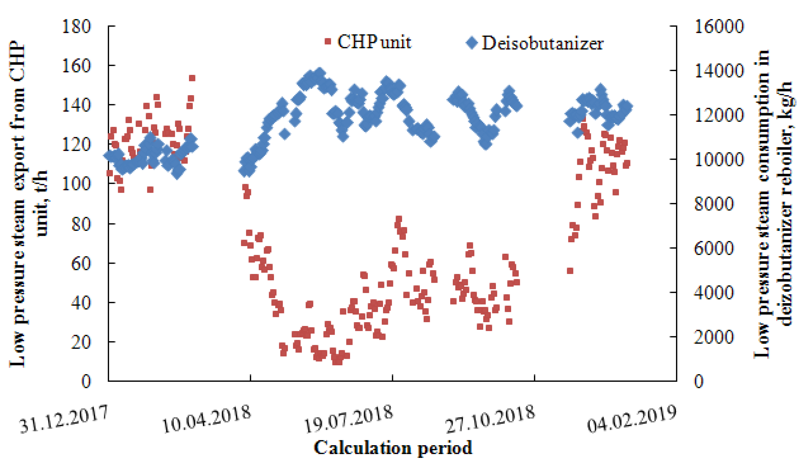
Figure 9 provides an insight into seasonal variation of 0.5 MPa steam export from the CHP unit, m ˙ L P S , C H P . As seen in Table 5, the largest backpressure electric energy amount is cogenerated and, thus, its export influences the total electric energy production of the CHP unit. In Figure 9, frequent drops below 30 t/h can be seen in summer. As a result, CHP unit electric energy production drops close to or below 35 MW. Condensing power production increases in such situations to compensate for the low backpressure power production, which results in fuel consumption increase by a factor of 3 MWh/ton of fuel as observed by the CHP unit operators [39]. The calculation model incorporates this seasonal feature in Equation (41), with s = 1 to 3 denoting the high, middle, and low pressure steam export from CH unit, respectively:
i f   m ˙ L P S , C H P < 30   t . h 1 t h e n   m ˙ f u e l , C H P , s u m m e r [ t o n   o f   H F O   p e r   h o u r ] = s = 1 3 ( Δ m ˙ C H P , s .0.09 [ t o n   o f   H F O   p e r   t o n   o f   s t e a m ] ) Δ P b p , C H P [ M W ] 3 [ M W h t o n   o f   f u e l ]
Figure 9 also shows that the total 0.5 MPa steam export from the CHP unit occasionally decreases to close to 10 t/h, which negatively affects the low pressure steam network operation stability. Therefore, it has to be maintained at or above 10 t/h. Any excess low pressure steam due to its consumption reduction in the refinery is vented to the atmosphere. This particular low pressure steam balance feature is a part of the calculation model. Another system feature visible in Figure 9 is that low pressure steam consumption in the deisobutanizer reboiler is comparable with the total low pressure steam export from the CHP unit in summer, meaning that changes in its consumption will significantly affect the CHP unit operation.
Table 7 sums up other fixed calculation inputs regarding the CHP unit operation and CO2 emissions assessment.

2.2.3. Total Investment Cost Estimation

TIC estimation followed the procedure used in reference literature [41,42]. Key equipment sizing proceeded as follows:
Heat exchangers: maximum heat duty observed during the calculation period was multiplied by a factor of 1.2 to allow for possible process intensification in future. Overall heat transfer coefficient, U = 700 W m−2 K−1, was used in heat transfer Equation (42). The applied value of U represents an average of light hydrocarbons reboiled on the process side and condensing on the other side [41]. Heat transfer driving force was simply defined as the difference between minimum hot utility temperature, t h o t m i n , and maximum cold utility temperature,   t c o l d m a x :
A H E X = 1.2 Q ˙ H E X , m a x U ( t h o t m i n t c o l d m a x ) .
The resulting heat exchanger surface, A H E X , from Equation (42) was divided by two, if its value exceeded 1000 m2.
Heat pump compressor: total investment cost of €1000 per kW of installed power input was considered based on our previous experience. Installed power input was estimated as the maximum power input required by the heat pump compressor during the calculation period multiplied by the factor of 1.2.
Combustion engine: delivered cost of €200 per kW of installed power output was considered [41]. Regarding the usual values of deisobutanizer reboiler heat duty and the calculated heat pump compressor energy consumption, the Jenbacher J920 FlexTra gas engine [34] was selected as the most suitable unit.
Steam turbine with generator: total investment of €200 per kW of installed power output was considered based on similar investment actions in the refinery in the past.
The obtained key equipment cost was then adjusted by including the equipment pressure factor and recalculated to 2020 price level from the 2002 base price level used in [41] by the CEPCI index. The resulting equipment cost was then converted to TIC by applying suitable Lang factors.

3. Results

3.1. Model Verification

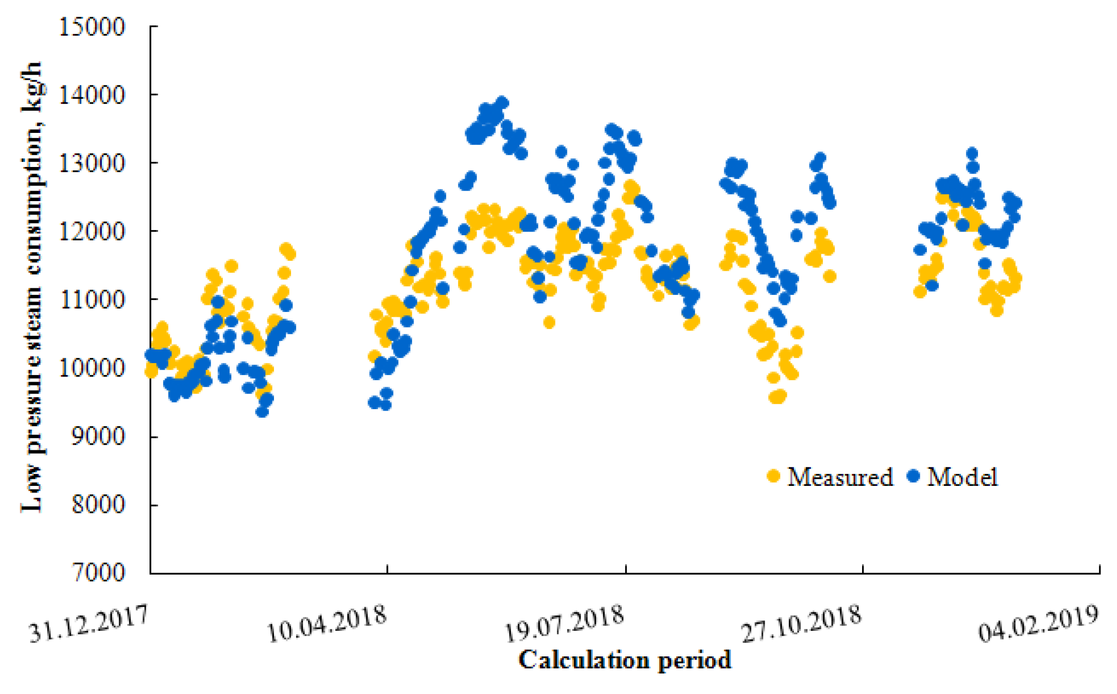
Deisobutanizer model results were compared with process data. The comparison of model results and measured low pressure steam consumption in the deisobutanizer reboiler is provided in Figure 10. As it appears, column model is able to predict the steam consumption very well for a wide range of operational states experienced during the calculation period. Thus, the calculation model is validated and is used for energetic, environmental, and economic assessment of the considered revamp options. Table 8 contains a daily average sample of calculated deisobutanizer operation data that served as inputs for Case A and Case B and calculations regarding the traditional electromotor-driven compression heat pump.

3.2. Investment Scope and Cost

Detailed investment scope and the resulting TIC estimation for Case B is provided in Table 9. The majority of TIC can be assigned to the combustion engine, followed by the heat pump part. Table 10 compares the estimated TIC for Case A, Case B, and for the model heat pump. The model heat pump solution is roughly 50% less expensive than Case B as it requires no combustion engine to be installed.

3.3. CO2 Balances

Results of CO2 emissions balance are shown in Table 11. Refinery level CO2 emissions increase is evident in both Case A and Case B. Taking into account the external CO2 emissions due to the change in purchased electric energy, this proposal yields their overall decrease in both cases by up to 29 kton/year (Case B). The model heat pump decreases the CO2 emissions on the refinery level by 15.5 kton/year but only by 4–14 kton/year globally as a result of significant external CO2 emissions increase. External power production emission factor used in the calculations affects the results significantly, changing the overall environmental performance of individual solutions completely.

3.4. Economics and Sensitivity Analysis

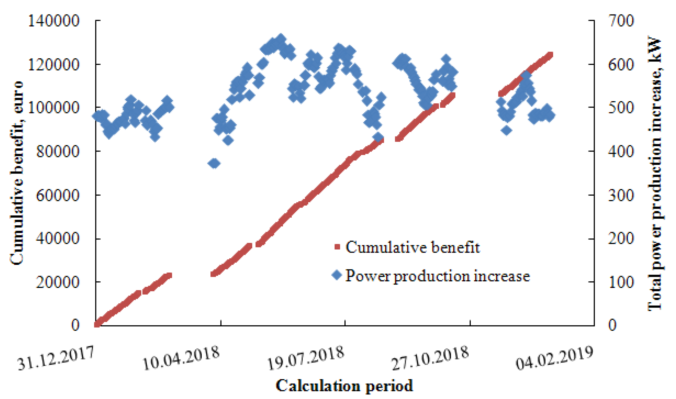
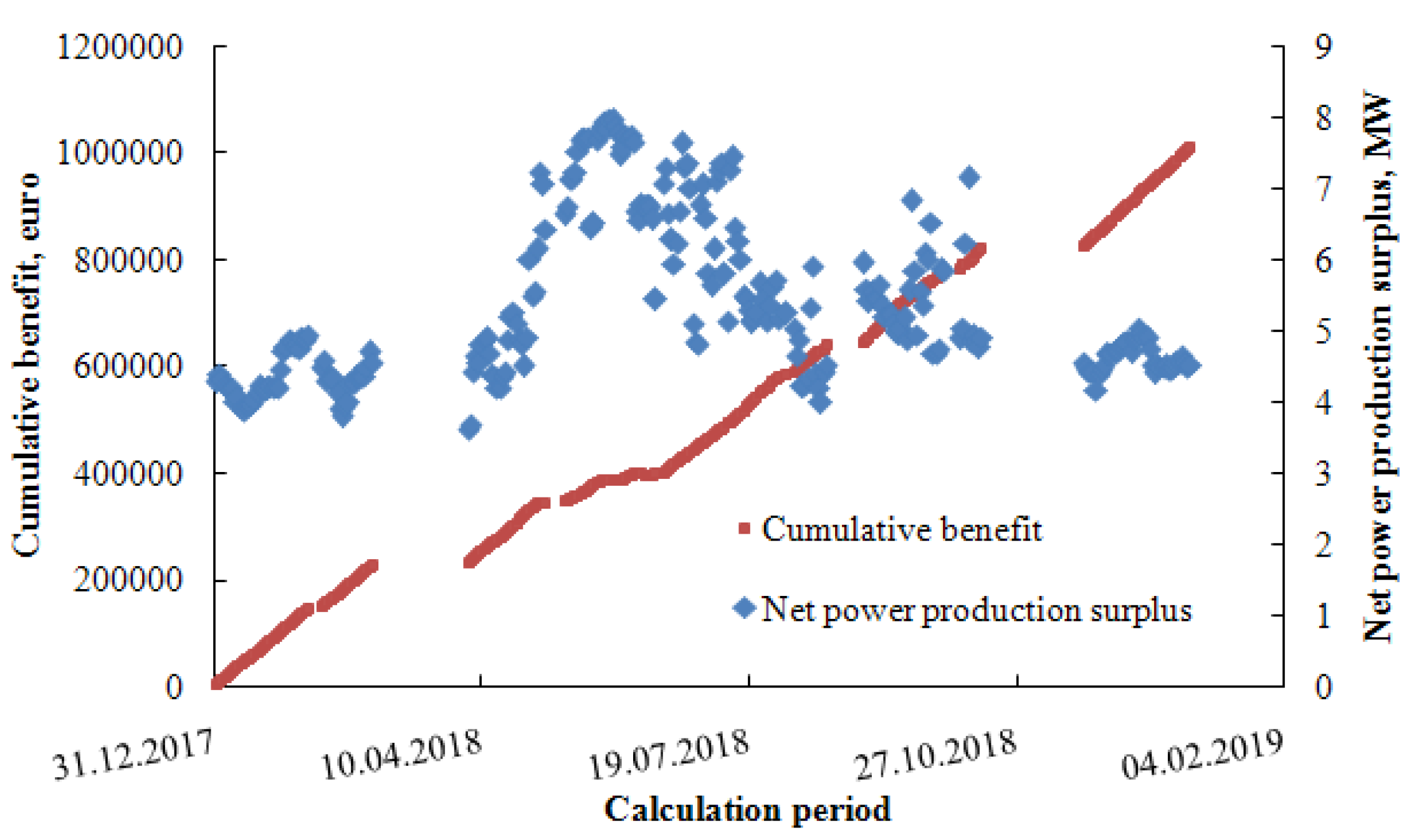
Cumulative benefit over the calculation period for Case A, Case B, and model electro-driven heat pump is provided in Figure 11, Figure 12 and Figure 13. Figure 11 provides the values of underlying power production increase ranging between 400 and 650 kW. Its variability is caused mostly by the varying steam consumption in the deisobutanizer reboiler as well as by the varying turbine discharge pressure. Steam turbine clearly benefits from lower reboiler temperatures allowing for more intense cogeneration potential exploitation. Yearly benefit of €120 thousand is achieved with around 250 days of stable alkylation unit operation in 2018 and it might exceed €150 thousand in an ordinary year when fewer production interruptions occur than in 2018.
Figure 12 clearly documents seasonal variation of net power production surplus in Case B. Summer operation mode leads to its increased values and smaller benefit, whereas lower power production boost is experienced in winter, accompanied by larger benefit. The reason for this phenomenon is the CHP unit operation: low pressure steam saving in winter decreases backpressure power production and saves fuel in steam boilers. Limited low pressure steam saving is possible in summer due to minimal power production requirement in the CHP and minimal low pressure steam export limit to ensure stable steam pipelines operation. Fuel saving in winter contributes to the cumulative benefit far more significantly than higher net power production in summer at the expense of fuel consumption.
These observations underline the need to assess each revamp or energy saving proposal from the seasonal point of view. Summer and winter benefits can differ significantly, which should be acknowledged in scientific literature presenting both case studies and optimization methods for the design and operation of production processes.
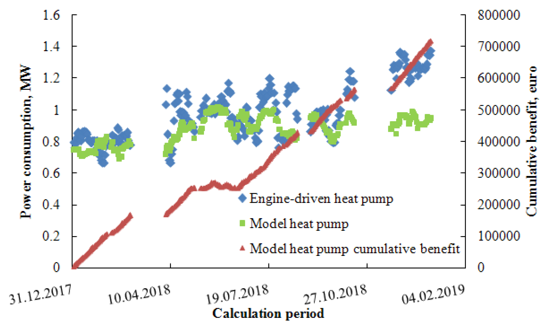
A comparison of Case B performance with that of model electro-driven heat pump is presented in Figure 13. COP value of 8, corresponding to a temperature increase of around 20 °C, was chosen for the model heat pump to match its power consumption with that calculated for the engine-driven heat pump, assuming that waste heat is available at sufficiently high temperatures (above 80 °C). The difference in yearly cumulative benefit of around €300 thousand favors the installation of the combustion engine drive. Summer operation of the electro-driven heat pump is economically infeasible in some days, despite the waste heat being freely available, but is almost as beneficial as that of the engine-driven pump in winter. This again accentuates the need for complex benefit assessment as presented in this study incorporating both seasonal system operation variations and its constraints resulting from system specificities.
Benefit and NPV sensitivity analysis was performed to better understand its dependence on key variables. Its outcome as well as the resulting simple payback period values are summed up in Table 12. Base energies and media prices set yield comparable payback period values for Case A and Case B. The simple payback period value for the model heat pump is shorter and its NPV is higher than in the other two cases. However, total investment estimate for the model heat pump is incomplete, since no suitable waste heat source is present in the alkylation process. If a system for heat collection and transfer to connect the alkylation unit and possible heat sources located in adjacent units is to be built, significant investment cost increase in the model heat pump case can be anticipated, possibly elongating the corresponding payback period beyond that of Case A and Case B.
Cases A and B do not benefit from fuel price increase since they lead to a net fuel consumption increase. Under the assumption that waste heat for model heat pump is free, the payback period of model heat pump investment becomes shorter with the increasing fuel price and its NPV increases by more than 50% whereas that for Cases A and B drops below zero. It has to be noted that even a modest waste heat price of €2 per GJ (representing around 30% of fuel price per GJ) leads to model heat pump investment infeasibility and negative NPV value. CO2 price increase has the same effect as fuel price increase: negative impact on the payback period in Cases A and B is seen, whereas that of the model heat pump is considerably shortened and its NPV more than doubles compared to its base case value.
Electricity price increase affects the economics of both Case A and Case B positively since they generate a surplus on electricity with their NPVs being more than triple (Case B) and more than quadruple (Case A), respectively, compared to their base case values. The model heat pump is, on one hand, an electricity consumer but on the other hand it causes electricity production decrease in the CHP unit. Hence, its economic performance worsens with its price increase.
Energetic efficiency of Case B can be assessed by evaluating its marginal electric efficiency, defined by Equation (30). The refinery decreases electric energy purchase by 32.95 GWh and uses 42.05 GWh more fuel energy on a yearly basis. This yields the marginal electric efficiency of 78.4%, which is far higher than that of the combustion engine itself. Such high value of marginal electric efficiency indicates that the combustion engine-driven heat pump-assisted rectification of the alkylation reactor effluent is a truly integrated solution benefiting from system synergies.
It can be concluded that with a suitable combination of energies and media prices, all investigated cases can be economically attractive. Economic viability of the proposed novel alkylation reactor effluent heat pump-assisted splitting with combustion engine incorporation is thereby proven and found to be comparable with the traditional electro-driven heat pump solution. The most important findings resulting from the performed modeling include:
  • The whole refinery, including its CHP unit, has to be included in the balancing scheme when evaluating the energetic, ecological, and economic performance of any process revamp.
  • System specificities and seasonal operation variations must be incorporated in the calculation model to yield a realistic assessment of proposed revamp alternatives. Technical and operational constraints resulting from these system features affect their economics significantly, leading to e.g., periods with economically infeasible operation during summer.
  • CO2 balancing on the refinery level is insufficient to assess the ecological footprint of the individual revamp alternatives. CO2 emissions change resulting from the refinery’s electric energy balance can be comparable or even larger than that of the refinery itself.

4. Discussion

In this paper, new alternatives in alkylation reactor effluent separation are presented, namely water stream cogeneration potential exploitation and combustion engine-driven heat pump implementation. For the sake of comparison, a model electromotor-driven heat pump installation was assessed.
Heating steam pressure reduction by a steam engine requires, amongst other changes, installation of a new reboiler resulting in a moderate investment. Assuming the investment cost of €1.15 million and yearly electric energy production increase of approx. 3.3 GWh, the economic analysis indicated a simple payback period of 8 to 10 years and an NPV of −€18 to €272 thousand. At the same time, global yearly decrease of CO2 emission by 3 kton can be anticipated.
A combustion engine-driven heat pump utilizing the drive’s sufficient-level heat and mechanical energy is a complex solution of the process and the necessary investment of approx. €9 million is considerably significant. However, the resulting yearly financial benefit of €0.9 to 1.2 million compensates for the cost adequately. This revamp solution exhibits an NPV value of −€293 to €2823 thousand. The expected annual decrease in global emissions can reach up to 26 kton depending on the considered emission factor. This application decreases the electric energy purchase by 33 GWh/year while increasing the energy consumption in the means of fuel by 42 GWh/year representing the marginal electric efficiency of the combustion engine integration to be over 78%, which indicates significant system synergy and effectiveness of the proposed solution.
A traditional alternative, i.e., an electromotor-driven heat pump, was modeled with the electric energy consumption comparable to that of the combustion engine. The expected investment of €4.6 million results in a shorter simple payback period and an NPV value ranging between −€496 and €5413 thousand. However, this alternative assumes an existence of a suitable waste heat source in the refinery which may not always be true. Moreover, the anticipated investment does not include the expense of waste heat transfer from adjacent units. This alternative’s main benefit is refinery-level CO2 emissions decrease, which is however strongly reduced or even eliminated if external CO2 emissions are taken into account. Its financial benefit may not be achieved as it strongly depends on the electric energy production in the refinery and on the actual emission factor. Thus, if the price of electric energy increases by 10%, the payback periods of electro-driven and combustion engine-driven alternatives equalize. Assuming the waste heat price to be 30% of the fuel price, the electro-driven alternative’s simple payback period prolongs to more than 10 years. All investigated revamp options exhibit a longer simple payback period than that reported in [29] for heat pump applications as the process heat is produced in the refinery’s CHP unit, which means that its substitution by another heat source reduces power production; moreover, heating steam excess in summer has to be considered.

5. Conclusions

The proposed methodology deals with multilevel process assessment considering process operation, economics, and environmental impact. Various alkylation revamp alternatives were analyzed and discussed. The most relevant conclusions that can be applied generally and contribute to knowledge in the techno-economic assessment of production process revamp projects include (I) balancing control volume should include the energies and media source as its operation variations impact the individual revamp options significantly; (II) system specificities including the heat and steam transportation system should be considered carefully. Operational constrictions of these systems can influence the expected revamp options performance negatively; (III) for CO2 balancing purposes, external power generation sources should be included in the control volume. A suitable power production emission factor should be used.

Author Contributions

Conceptualization, M.V., L.Š., P.F. and N.K.; data curation, P.F. and N.K.; funding acquisition, J.K. and M.R.; investigation, L.Š., P.F. and J.V.; methodology, M.V. and O.M.; resources, P.I. and N.K.; software, J.J. and P.F.; visualization, J.J. and J.V.; writing—original draft preparation, M.V. and P.F.; writing—review and editing, M.R., J.K. and O.M. All authors have read and agreed to the published version of the manuscript.

Funding

This work was financially supported by the Slovak Research and Development Agency under the contracts No. APVV-16-0192, APVV-15-0148 and APVV-18-0134.

Acknowledgments

The authors would like to express many thanks to all SLOVNAFT, a.s., employees who contributed to the final scope and form of this paper.

Conflicts of Interest

The authors declare no conflict of interest.

Nomenclature

Symbols
ayear, Equation (39)
A area, m2
A 1 A 6 Equation (8) parameters
B ˙ benefit over time, € hour−1, € year−1
B 1 B 5 Equation (11) parameters
c cost, €
C ˙ cost over time, € h−1
C 1 C 4 Equation (12) parameters
C O P coefficient of performance
c p isobaric molar heat capacity, kmol kg−1 K−1
ddiscount rate
e electric energy production rate, kJ h−1
E ˙ mechanical energy consumption, kJ h−1
E M V Murphree stage efficiency
f emission factor
F feedstock molar flow rate, kmol h−1
h molar enthalpy, kJ kmol−1
Δ v h heat of vaporization, kJ kmol−1
K vapor-liquid equilibrium constant
L liquid phase molar flow rate, kmol h−1
L H V lower heating value, kJ kg−1
m ˙ mass flow rate, kg h−1
M molar mass, kg kmol−1
N I number of components
NPVNet Present Value, €
p pressure, kPa
p ° saturated vapor pressure, kPa
P power production rate, kJ h−1
P B P payback period, year
Q ˙ heat flux, kJ h−1
R universal gas constant, J mol−1 K−1
t temperature, °C
T thermodynamic temperature, K
T I C total investment cost, €
U overall heat transfer coefficient, W m−2 K−1
V vapor phase molar flow rate, kmol h−1
w component mass fraction
x liquid molar fraction
y vapor molar fraction
z compressibility factor
Superscripts
dischdischarge conditions
Ffeedstock conditions
ininlet conditions
ISisoentropic conditions
Lliquid phase
maxmaximal
minminimal
netnetto value
outoutlet conditions
Vvapor phase
Subscripts
addadditional
bpbackpressure
CHPreferring to Combined Heat and Power Unit
condreferring to condensate
demidemineralized (water)
DFdegrees of freedom
elelectric (efficiency)
engreferring to engine
evapreferring to evaporator
extexternal
ffuel numbering
htime period numbering (hour)
heatreferring to waste heat
HEXreferring to heat exchanger
hpreferring to heat pump
icomponent numbering
impimport
ISisoentropic (efficiency)
jstage numbering
LPSreferring to low pressure steam
margmarginal
mechmechanical (efficiency)
rreference
Rreduced
rebreferring to reboiler
recrecuperated
refreferring to refinery
spressure level numbering
streferring to steam turbine
ththermal (efficiency)
Greek symbols
κ Poisson’s coefficient
η efficiency

Abbreviations

C4hydrocarbons with four carbon atoms in the molecule
CHPcombined heat and power unit
MESHmass, equilibrium, summation and heat balances
SCsimultaneous correction

References

  1. Energy Information Administration. International Energy Outlook 2016; Energy Information Administration, U.S. Department of Energy: WA, USA, 2016. Available online: https://www.eia.gov/outlooks/ieo/pdf/0484(2016).pdf (accessed on 15 January 2019).
  2. Morrow, W.R., III; Marano, J.; Hasanbeigi, A.; Masanet, E.; Sathaye, J. Efficiency improvement and CO2 emission reduction potentials in the United States petroleum refining industry. Energy 2015, 93, 95–105. [Google Scholar] [CrossRef] [Green Version]
  3. Gorak, A.; Sorensen, E. Distillation: Fundamentals and Principles; Academic Press: Cambridge, MA, USA, 2014; ISBN 978-0-12-386547-2. [Google Scholar]
  4. Worell, E.; Corsten, M.; Galitsky, C.H. Energy Efficiency Improvement and Cost Saving Opportunities for Petroleum Refineries. In An ENERGY STAR® Guide for Energy and Plant Managers; A Document Prepared for The United States Environmental Protection Agency; 2015. Available online: www.energystar.gov/industry (accessed on 4 June 2018).
  5. García, N.; Fernández-Torres, M.J.; Caballero, J.A. Simultaneous environmental and economic process synthesis for isobutene alkylation. J. Clean. Prod. 2014, 81, 270–280. [Google Scholar] [CrossRef] [Green Version]
  6. Kumar, P.; Vermeiren, W.; Dath, J.P.; Hoelderich, W.F. Production of alkylated gasoline using ionic liquids and immobilized ionic liquids. Appl. Catal. A 2006, 304, 131–141. [Google Scholar] [CrossRef]
  7. Hiladgo, J.M.; Zbuzek, M.; Černý, R.; Jíša, P. Current uses and trends in isomerization, alkylation and etherification processes to improve gasoline quality. Cent. Eur. J. Chem. 2014, 12, 1–13. [Google Scholar]
  8. Di Girolamo, M.; Tagliabue, L. MTBE and alkylate co-production: Fundamentals and operating experience. Catal. Today 1999, 52, 307–319. [Google Scholar] [CrossRef]
  9. Khvostenko, N.N.; Lagutenko, N.M.; Kurylev, V.D.; Kirillov, D.V.; Esipko, B.A. Modernization of a sulfuric acid alkylation unit. Chem. Technol. Fuels Oils 2000, 36, 18–20. [Google Scholar] [CrossRef]
  10. Wang, D.; Zhang, T.; Yang, Y.; Tang, S. Simulation and design microreactor configured with micromixers to intensify the isobutane/2-butene alkylation process. J. Taiwan Inst. Chem. Eng. 2019, 98, 53–62. [Google Scholar] [CrossRef]
  11. Tsadkin, M.A.; Badikova, A.D.; Mortikov, E.S. The formation of emulsions during the jet mixing of reagent flows as applied to the sulfuric acid alkylation of iso-butane with olefins. Theor. Found. Chem. Eng. 2016, 50, 165–170. [Google Scholar] [CrossRef]
  12. Tsadkin, M.A.; Badikova, A.D. Industrial trials of a new generation contactor for the process of the sulfuric-acid alkylation of isobutene with olefins. Theor. Found. Chem. Eng. 2018, 52, 246–257. [Google Scholar] [CrossRef]
  13. Li, Y.; Liu, R.; Zhao, G.; Zhou, Z.; Zhang, J.; Shi, C.H.; Liu, X.; Zhang, X.; Zhang, S. Simulation and optimization of fixed bed solid acid catalyzed isobutene/2-butene alkylation process. Fuel 2018, 216, 686–696. [Google Scholar] [CrossRef]
  14. Ivanchina, E.D.; Kirgina, M.V.; Chekantsev, N.V.; Sakhnevich, B.V.; Sviridova, E.V.; Romanovskiy, R.V. Complex modeling system for optimization of compounding process in gasoline pool to produce high-octane finished gasoline fuel. Chem. Eng. J. 2015, 282, 194–205. [Google Scholar] [CrossRef]
  15. Nurmakanova, A.E.; Ivashkina, E.N.; Ivanchina, E.D.; Dolganov, I.A.; Boychenko, S.S. Predicting alkylate yield and its hydrocarbon composition for sulfuric acid catalyzed isobutane alkylation with olefins using the method of mathematical modeling. Procedia Chem. 2015, 15, 54–64. [Google Scholar] [CrossRef] [Green Version]
  16. Kiss, A.A.; Ferreira, C.A.I. Chapter 10. Case studies. In Heat Pumps in Chemical Process Industry; CRC Press, Taylor & Francis Group: Boca Raton, FL, USA, 2017; ISBN 9781315371030. [Google Scholar]
  17. Liu, L.; Zhu, L.; Sun, L.; Zhu, M.; Liu, G. Simulation and optimization of different pressure thermally coupled distillation for separating a close-boiling mixture of n-butanol and iso-butanol. Appl. Petrochem. Res. 2017, 7, 143–150. [Google Scholar] [CrossRef] [Green Version]
  18. Demirel, Y. Thermodynamic Analysis of Separation Systems. Papers Therm. Mech. 2004, 39, 3897–3942. [Google Scholar] [CrossRef] [Green Version]
  19. Lee, J.; Son, Y.; Lee, K.S.; Won, W. Economic analysis and environmental impact assessment of heat pump-assisted distillation in a gas fractionation unit. Energies 2019, 12, 852. [Google Scholar] [CrossRef] [Green Version]
  20. Danilov, Y.; Sinkevich, I.; Lavrova, I.; Mardupenko, A.; Tulskaya, A. Energy saving technologies in the petroleum refining processes. Pet. Coal 2018, 60, 128–133. [Google Scholar]
  21. Kazemi, A.; Hosseini, M.; Mehrabani-Zeinabad, A.; Faizi, V. Evaluation of different vapor recompression distillation configurations based on energy requirements and associated costs. Appl. Therm. Eng. 2016, 94, 305–313. [Google Scholar] [CrossRef]
  22. Variny, M.; Furda, P.; Kováč, N.; Mierka, O. Analysis of C3 fraction splitting system performance by mathematical modeling in MATLAB environment. Acta Chim. Slovaca 2019, 12, 127–135. [Google Scholar] [CrossRef] [Green Version]
  23. Long, N.V.D.; Lee, M.Y. Design and optimization of heat integrated dividing wall columns for improved debutanizing and deisobutanizing fractionation of NLG. Korean J. Chem. Eng. 2013, 30, 286–294. [Google Scholar] [CrossRef]
  24. You, X.; Rodriguez-Donis, I.; Gerbaud, V. Reducing process cost and CO2 emissions for extractive distillation by double-effect heat integration and mechanical heat pump. Appl. Energy 2016, 166, 128–140. [Google Scholar] [CrossRef] [Green Version]
  25. Song, D.; Yoon, Y.-G.; Seo, S.-K.; Lee, C.H.-J. Improvement of 1,3-butadiene separation in 2,3-butanediol dehydration using extractive distillation. Processes 2019, 7, 410. [Google Scholar] [CrossRef] [Green Version]
  26. Asprion, N.; Rumpf, B.; Gritsch, A. Work flow in process development for energy efficient processes. Appl. Therm. Eng. 2011, 31, 2067–2072. [Google Scholar] [CrossRef]
  27. Yang, M.; Feng, X.; Liu, G. Heat integration of heat pump assisted distillation into the overall process. Appl. Energy 2016, 162, 1–10. [Google Scholar] [CrossRef]
  28. van de Boer, D.M.; Ferreira, C.A.I.; Kiss, A.A. Low grade waste heat recovery using heat pumps and power cycles. Energy 2015, 89, 864–873. [Google Scholar] [CrossRef]
  29. U.S. Department of Energy. Industrial Heat Pumps for Steam and Fuel Savings. A Best Practice Steam Technical Brief. 2003. Available online: https://www.energy.gov/sites/prod/files/2014/05/f15/heatpump.pdf (accessed on 12 December 2019).
  30. Bütün, H.; Kantor, I.; Maréchal, F. Incorporating location aspects in process integration methodology. Energies 2019, 12, 3338. [Google Scholar] [CrossRef] [Green Version]
  31. Rimár, M.; Fedák, M.; Abraham, M.; Kulikov, A.; Váhovský, J. The efficiency of the cogeneration unit implemented in the CHS system in terms of heat generation. Acta Tecnol. Int. Sci. J. Technol. 2017, 3, 9–13. [Google Scholar] [CrossRef]
  32. Variny, M.; Blahušiak, M.; Mierka, O.; Godó, Š.; Margetíny, T. Energy saving measures from their cradle to full adoption with verified, monitored, and targeted performance: A look back at energy audit at Catalytic Naphtha Reforming Unit (CCR). Energy Eff. 2019, 12, 1771–1793. [Google Scholar] [CrossRef]
  33. Sarco, S. The steam and condensate loop. In Effective Steam Engineering for Today; Spirax-Sarco Limited: Cheltenham, UK, 2011; ISBN 978-0-9550691-5-4. [Google Scholar]
  34. INNIO. Product Flyer, Jenbacher j920 Flextra Combustion Engine. 2019. Available online: https://www.innio.com/en/products/jenbacher/j920-flextra#brochures/j920-flextra-brochure (accessed on 11 October 2019).
  35. Rimár, M.; Abraham, M.; Fedák, M.; Kulikov, A.; Oravec, P.; Váhovský, J. Methods for increasing the efficiency of cogeneration based energy equipment. Modern Mach. Sci. J. 2019, 12, 2935–2938. [Google Scholar] [CrossRef]
  36. Flimel, M. Potential Optimisation of Heat Pump Placement in Terms of Environmental Noise Levels. In Heat Pumps. Performance and Applications; Espenson, T., Ed.; Nova Science Publishers Inc.: New York, NY, USA, 2018; ISBN 978-1-53614-341-6. [Google Scholar]
  37. Bejan, A. Advanced Engineering Thermodynamics, 4th ed.; John Wiley & Sons: Hoboken, NJ, USA, 2016; ISBN 978-1119245964. Available online: https://app.knovel.com/hotlink/toc/id:kpAETE0003/advanced-engineering/advanced-engineering (accessed on 5 October 2019).
  38. Yaws, C.L. Yaws’ Critical Property Data for Chemical Engineers and Chemists; Knovel, 2014; ISBN 978-1-61344-932-5. Available online: https://app.knovel.com/hotlink/toc/id:kpYCPDCECD/yaws-critical-property/yaws-critical-property (accessed on 6 October 2019).
  39. Variny, M.; Jediná, D.; Kizek, J.; Illés, P.; Lukáč, L.; Janošovský, J.; Lesný, M. An Investigation of the Techno-Economic and Environmental Aspects of Process Heat Source Change in a Refinery. Processes 2019, 7, 776. [Google Scholar] [CrossRef] [Green Version]
  40. Smith, C.N.; Hittinger, E. Using marginal emission factors to improve estimates of emission benefits from appliance efficiency upgrades. Energy Eff. 2019, 12, 585–600. [Google Scholar] [CrossRef]
  41. Peters, M.S.; Timmerhaus, K.D.; West, R.E. Plant Design and Economics for Chemical Engineers, 5th ed.; International Edition; McGraw-Hill: New York, NY, USA, 2003; ISBN 0-07-239266-5. [Google Scholar]
  42. Holland, F.A. Process Economics. In Perry’s Chemical Engineers’ Handbook, 7th ed.; Perry, R.H., Ed.; McGraw-Hill Professional: London, UK, 1997; ISBN 0-07-049841-5. [Google Scholar]
  43. Variny, M.; Blahušiak, M.; Janošovský, J.; Hruška, M.; Mierka, O. Optimization study on a modern regeneration boiler cold end operation and its feedwater system integration into energy system of a paper mill. Energy Eff. 2019, 12, 1595–1617. [Google Scholar] [CrossRef]
  44. Boonekamp, P.G.M. Evaluation of methods used to determine realized energy savings. Energy Policy 2006, 34, 3977–3992. [Google Scholar] [CrossRef] [Green Version]
  45. El-Temtamy, S.A.; Gendi, T.S. Economic evaluation and sensitivity analysis of some fuel oil upgrading processes. Egypt. J. Pet. 2014, 23, 397–407. [Google Scholar] [CrossRef] [Green Version]
  46. Eurostat. Annual Average Change of Harmonized Index of Consumer Prices in the 2007–2018 Period. 2019. Available online: https://ec.europa.eu/eurostat/tgm/table.do?tab=table&init=1&language=en&pcode=tec00118&plugin=1 (accessed on 10 January 2020).
  47. Seader, J.D.; Henley, E.J.; Roper, D.K. Separation Process Principles with Applications using Process Simulators, 3rd ed.; Wiley: Hoboken, NJ, USA, 2010; ISBN 978-0470481837. [Google Scholar]
  48. Towler, G.; Sinnot, R. Chemical Engineering Design—Principles, Practice and Economics of Plant and Process Design, 2nd ed.; Elsevier: Amsterdam, The Netherlands, 2013; ISBN 978-0080966601. Available online: https://app.knovel.com/hotlink/toc/id:kpCEDPPEP4/chemical-engineering/chemical-engineering (accessed on 5 October 2019).
  49. Friend, D.G. Physical and Chemical Data. In Perry’s Chemical Engineers’ Handbook, 7th Ed.; Perry, R.H., Ed.; McGraw-Hill Professional: London, UK, 1997; ISBN 0-07-049841-5. [Google Scholar]
  50. Yaws, C.L. Yaws’ Handbook of Thermodynamic Properties for Hydrocarbons and Chemicals; Knovel, 2009; ISBN 978-1-60119-797-9. Available online: https://app.knovel.com/hotlink/toc/id:kpYHTPHC09/yaws-handbook-thermodynamic/yaws-handbook-thermodynamic (accessed on 5 October 2019).
  51. Coker, A.K. Ludwig’s Applied Process Design for Chemical and Petrochemical Plants, 4th ed.; Elsevier: Amsterdam, The Netherlands, 2010; Volume 2, ISBN 978-0080942094. Available online: https://app.knovel.com/hotlink/toc/id:kpLAPDCP02/ludwigs-applied-process/ludwigs-applied-process (accessed on 6 October 2019).
  52. CHP Unit Scheme. Available online: http://www.cmep.sk/index.php/sk/teplaren (accessed on 11 March 2019). (In Slovak).
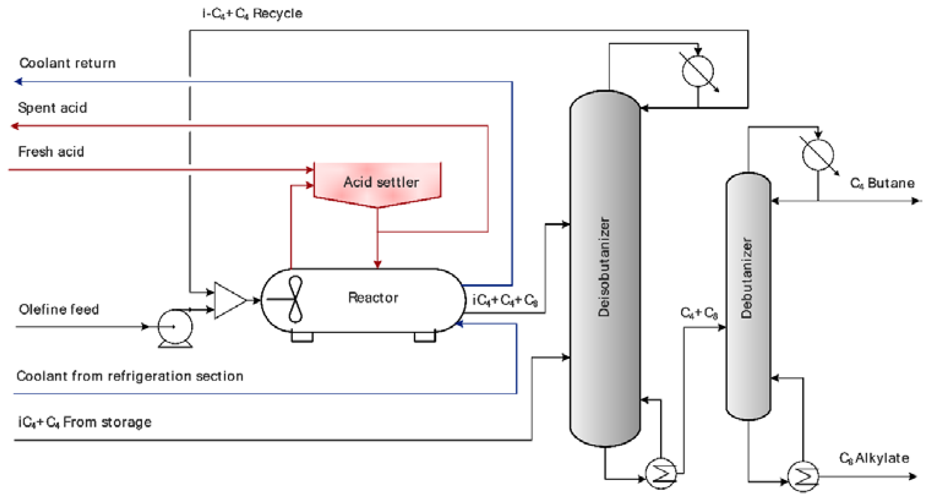
Figure 1. Traditional alkylation process layout. Adapted from [5].
Processes 08 00183 g001
Figure 2. Alkylation process revamp option via divided wall column installation. Adapted from [5].
Processes 08 00183 g002
Figure 3. Alkylation process revamp option via thermal coupling of rectification columns. Adapted from [5].
Processes 08 00183 g003
Figure 4. Alkylation process revamp option via heat pump-assisted C4 stream splitting. Adapted from [5].
Processes 08 00183 g004
Figure 5. Alkylation reactor effluent splitting layout in SLOVNAFT refinery.
Processes 08 00183 g005
Figure 6. Additional steam turbine installation in the alkylation process: “Case A”. New equipment, compared to the process layout depicted in Figure 5, is highlighted in red.
Processes 08 00183 g006
Figure 7. Combustion engine-based heat pump-assisted distillation: “Case B”. New equipment, compared to the process layout depicted in Figure 5, is highlighted in red.
Processes 08 00183 g007
Figure 8. Traditional electro-driven heat pump-assisted distillation with external waste heat delivery: reference solution. New equipment, compared to process layout depicted in Figure 5, is highlighted in red.
Processes 08 00183 g008
Figure 9. Overview of low pressure steam export from the CHP unit and its consumption in the deisobutanizer reboiler during the calculation period.
Processes 08 00183 g009
Figure 10. Comparison of modeled and measured low pressure steam consumption in the deisobutanizer reboiler.
Processes 08 00183 g010
Figure 11. Cumulative benefit and the underlying total power production increase over one year calculation period for Case A—additional steam turbine installation.
Processes 08 00183 g011
Figure 12. Cumulative benefit and the underlying net power production surplus over one year calculation period for Case B—combustion engine-driven heat pump installation.
Processes 08 00183 g012
Figure 13. Cumulative benefit for the model heat pump installation and a comparison of the power consumption for the model and the engine-driven heat pump.
Processes 08 00183 g013
Table 1. Fixed values of model inputs.
ParameterNumerical Value
Number of Stages70
Alkylate Feed Stage Number8
Butane Fraction Feed Stage Number29
Column Head/Bottom Pressure *, bar6/6.5
Alkylate Feed Temperature *, °C35
Butane Fraction Feed Temperature *, °C48
Alkylate Feed Vapor Fraction *0
Butane Fraction Feed Vapor Fraction *0
Alkylate Feed Composition, mol %
Alkylate *17.00
i-Butane *63.70
n-Butane *15.90
Propane *1.70
n-Pentane1.70
Butane Fraction Feed Composition, mol %
Alkylate *0
i-Butane *37.78
n-Butane *58.22
Propane *2.00
n-Pentane2.00
Column Bottoms’ Quality Requirement
Content of i-Butane *, mol %0.70
Table 2. Vapor pressures. Coefficients obtained from [49].
ComponentA1A2.10−3A3A4A5.106A6
Alkylate (Isooctane)77.81−6.8050−9.4396.7552
Isobutane58.78−4.3170−7.01710.372
n-Butane66.94−4.6040−8.25511.572
Propane52.38−3.4910−6.10911.192
n-Pentane63.33−5.1180−7.4837.7662
Table 3. Molar heat capacities. Coefficients obtained from [49] for alkylate, from [50] for propane, and from [51] for butanes and pentane.
ComponentB1B2.10B3.103B4.106B5.108
Alkylate (isooctane)95 2756 967−1 376.52 173.40
Isobutane71.7914.8472−2.05194.06340
n-Butane62.8735.8913−2.35884.22570
Propane121.525−10.982110.9178−43.01676.28137
n-Pentane80.6416.2195−2.26823.74230
Table 4. Molar heats of vaporization. Coefficients obtained from [49].
ComponentC1.10-7C2C3C4
Alkylate4.77210.3799200
Isobutane3.16670.3855000
n-Butane3.62380.83370−0.822740.39613
Propane2.92090.78237−0.773190.39246
n-Pentane3.91090.3868100
Table 5. Model inputs for heat pump working cycle and combustion engine.
Model ParameterEquation NumberNumeric Value
η m e c h , %1797
η I S , %1875
η t h , %2040
η e l , %2147
η h p , I S , %2275
η h p , m e c h , %2297
t h e a t m i n ,°C2580
Δ t e v a p m i n ,°C2510
Δ t r e b m i n ,°C2610
Table 6. Marginal backpressure electric energy production in the combined heat and power (CHP) unit, e b p , m a r g , C H P , s , in kWh per ton of expanding steam to the s-th pressure level.
Live Steam from Boilers → High Pressure SteamLive Steam from Boilers → Middle Pressure SteamLive Steam from Boilers → Low Pressure Steam
50105160
Table 7. Model inputs for CHP unit and assessment of CO2 emissions balance.
Model ParameterEquation NumberNumeric Value
w C , f f u e l for heavy fuel oil, %310.873
w C , f f u e l for natural gas, %310.748
f C O 2 , e x t average, kgCO2/MWh32135.5
f C O 2 , e x t marginal, kgCO2/MWh 32900
LHV for heavy fuel oil, MJ/kg 3540.5
LHV for natural gas, MJ/kg3548.9
Table 8. Calculated operation data for deisobutanizer column; 26 February 2018: daily average, corresponding to alkylate production of 13.5 t/h.
ParameterDeisobutanizer FeedDistillateBottoms
Molar flow, kmol/h805.25571.09234.16
Composition, % mol
Isooctane14.210.0048.87
n-pentane1.840.126.03
n-butane22.8413.9244.59
i-butane59.3683.490.51
propane1.752.470.00
Reflux ratio0.91
Column head temperature, °C48.4
Column bottom temperature, °C93.4
Heat duty reboiler, kW6210
Steam consumed in reboiler, calculated, t/h10.92
Steam consumed in reboiler, measured, t/h11.38
Table 9. Total investment cost estimation based on [41] for Case B.
EquipmentDesign Heat Duty, MWHeat Exchange Surface Needed, m2Purchased Cost Estimate (Year 2002), k€Purchased Cost Estimate (Year 2020) Corrected by Pressure Factors and Materials, k€
Reboiler for C1102 HXs, 650 each130190
Heat pump evaporator102 HXs, 650 each130190
Total purchased heat exchangers cost estimate, 103 €, year 2020380 = 100%
Purchased equipment installation50%
Combustion engine installed cost estimate, 103 €, year 20202000
Instrumentation and controls45%
Piping installed60%
Electrical systems20%
Buildings5%
Yard improvements15%
Service facilities installed15%
Engineering and supervision45%
Construction expenses40%
Legal expenses5%
Contractor’s fee20%
Contingency30%
TIC estimate, excl. heat pump compressor part, millions of €, year 20207.6
Heat pump compressor TIC estimate, millions of €, year 20201.5
TIC estimate, millions of €, year 20209.1
Table 10. Total investment cost (TIC) estimation for Case A, Case B, and model heat pump.
CaseABModel Heat Pump *
Estimated TIC, millions of €, year 20201.159.14.6
* Model heat pump TIC estimate does not include potential investment needed to ensure sufficient waste heat delivery for the heat pump from adjacent production units.
Table 11. CO2 emissions balance on the refinery level and the overall balance.
Classification of EmissionsCase ACase BModel Heat Pump
Refinery only, kton/year0.3423.551−15.507
External CO2 emissions, emission factor SE, a.s.−0.449−4.4891.795
Overall CO2 emissions−0.107−0.938−13.712
External CO2 emissions, marginal factor coal power plant−2.972−29.65311.877
Overall CO2 emissions−2.630−26.102−3.630
Table 12. Sensitivity analysis and simple payback period and net present value (NPV) values. Energies and media prices used in the base scenario include CO2 cost of €20 per ton, fuel price of €7 per GJ, cogenerated electric energy of €65 per MWh, electric energy consumed by electro-drives of €85 per MWh.
Cumulative Benefit, Thousands of € Per Year/Simple Payback Period, Years/NPV, Thousands of €Case ACase BModel Heat Pump *
Base scenario124.6/9.22/62.61011.0/9.00/739.1718.7/6.40/2394.4
Fuel price + 10%116.3/9.89/−18.2905.0/10.06/−292.5856.1/5.84/3731.6
Produced electricity price + 10%146.1/7.87/271.81225.1/7.43/2822.7633.0/7.90/1560.4
CO2 price + 100%117.8/9.76/−3.6940.0/9.68/48.11028.9/4.86/5413.3
Heat price €2 per GJ for model heat pump--421.7/11.86/−496.0
* Does not include investment cost needed to deliver waste heat from a suitable source to alkylation unit.